EP0326840A1 - Method and apparatus for producing a radiation image - Google Patents
Method and apparatus for producing a radiation imageDownload PDFInfo
- Publication number
- EP0326840A1 EP0326840A1EP89100650AEP89100650AEP0326840A1EP 0326840 A1EP0326840 A1EP 0326840A1EP 89100650 AEP89100650 AEP 89100650AEP 89100650 AEP89100650 AEP 89100650AEP 0326840 A1EP0326840 A1EP 0326840A1
- Authority
- EP
- European Patent Office
- Prior art keywords
- image
- line
- television camera
- screen
- radiation
- Prior art date
- Legal status (The legal status is an assumption and is not a legal conclusion. Google has not performed a legal analysis and makes no representation as to the accuracy of the status listed.)
- Granted
Links
- 230000005855radiationEffects0.000titleclaimsabstractdescription42
- 238000000034methodMethods0.000titleclaimsabstractdescription9
- 238000011156evaluationMethods0.000claimsabstractdescription5
- 238000012545processingMethods0.000claimsdescription13
- 238000005259measurementMethods0.000claimsdescription5
- 230000007547defectEffects0.000abstract1
- 230000005540biological transmissionEffects0.000description4
- 238000002591computed tomographyMethods0.000description4
- 230000001066destructive effectEffects0.000description4
- 238000012360testing methodMethods0.000description3
- 238000004154testing of materialMethods0.000description3
- 238000010586diagramMethods0.000description2
- 230000003287optical effectEffects0.000description2
- 238000003384imaging methodMethods0.000description1
- 238000013519translationMethods0.000description1
Images
Classifications
- G—PHYSICS
- G01—MEASURING; TESTING
- G01N—INVESTIGATING OR ANALYSING MATERIALS BY DETERMINING THEIR CHEMICAL OR PHYSICAL PROPERTIES
- G01N23/00—Investigating or analysing materials by the use of wave or particle radiation, e.g. X-rays or neutrons, not covered by groups G01N3/00 – G01N17/00, G01N21/00 or G01N22/00
- G01N23/02—Investigating or analysing materials by the use of wave or particle radiation, e.g. X-rays or neutrons, not covered by groups G01N3/00 – G01N17/00, G01N21/00 or G01N22/00 by transmitting the radiation through the material
- G01N23/04—Investigating or analysing materials by the use of wave or particle radiation, e.g. X-rays or neutrons, not covered by groups G01N3/00 – G01N17/00, G01N21/00 or G01N22/00 by transmitting the radiation through the material and forming images of the material
- G01N23/043—Investigating or analysing materials by the use of wave or particle radiation, e.g. X-rays or neutrons, not covered by groups G01N3/00 – G01N17/00, G01N21/00 or G01N22/00 by transmitting the radiation through the material and forming images of the material using fluoroscopic examination, with visual observation or video transmission of fluoroscopic images
Definitions
- the inventionrelates to a method and a device for generating a radiographic image with a radiation source for high-energy radiation arranged on one side of a body and a receiving device for the radiographic image arranged on the other side of the body, in particular for use in non-destructive material testing.
- a device for non-destructive radiation testingin which the rays of an X-ray or gamma radiation source penetrate a workpiece arranged between the radiation source and a luminescent screen and generate a radiation image on a luminescent screen, which is transmitted to a television monitor by means of a television chain transmission is mapped.
- the radiographis reproduced in real time and is a shadow image that shows materials of different densities or thicknesses of different brightness.
- there are very often large and very large differences in thicknessfor example in the case of engine blocks, welds and other complex components.
- a radiation method and a radiation device for material testingare known, in which a spatially resolving radiation detector and a radiation source are arranged in a plane spanned by the radiation source and the radiation detector about a perpendicular axis relative to the examination material by means of a rotatable slide are.
- the local distribution of the radiation intensityis determined at each rotation angle with the aid of evaluation electronics.
- a multiplicity of measurements in different angular positionsare carried out in a thin layer, which is determined by the plane spanned by the radiation source and the radiation detector, and a linear radiation projection is determined in each case.
- These various projectionsare processed in an electron computer by logarithmization, folding and unfolding in the manner known from computer tomography to produce a slice image of the examination subject and then displayed on a screen or otherwise stored.
- the inventionhas for its object to provide a method and an apparatus for generating a radiographic image, with which it is possible to examine a body relatively quickly and yet with great accuracy for errors.
- This objectis achieved according to the invention in a device of the type mentioned at the outset by combining a real-time playback chain for the radiographic image with a television camera, a screen and a computer tomograph for line-by-line evaluation of the radiographic image and displaying a cross section of the irradiated body on the screen.
- the recording device for the radiographic imagecan consist of an X-ray image intensifier and a television camera connected downstream.
- the recording device for the radiographic imagecan consist of an X-ray screen with a light amplifier connected downstream and a television camera.
- a position-resolving line detectorcan be arranged in the beam path of the transmission image, the television camera and / or the line detector can be arranged movably, or the transmission image can be directed onto the television camera or the line detector by means of a movable mirror.
- a semitransparent mirrorin the beam path of the transmission image and to direct the transmitted or the mirrored image onto the television camera or the line detector.
- a position-resolving line detectoris used to provide the measurement data for the slice image, either a radiation source and recording device which can be rotated and adjusted in height relative to the body, or a rotatable and height-adjustable manipulator for the body to be irradiated or a rotatable manipulator for the body to be irradiated and a height adjustment device for the lines Detector and the radiation source required to adjust the body relative to the radiation source and the recording system or the line detector.
- the television imageis preferably used directly to provide the measured values for the computer tomograph.
- an image memoryis arranged behind the television camera and the computer tomograph is connected to the image memory for line-by-line evaluation of the image.
- the body to be examinedneed only be rotated step by step by means of the manipulator, while the operator selects and enters a desired line of the television picture in order to generate the slice picture therefrom.
- line markingscan be arranged on the screen, and a selected line marking can then be input into a line selection device which is operated with the height adjustment device of the manipulator or the line detector or the radiation source or with the image memory connected is.
- the line selection deviceis connected to the image processing device and the height adjustment device of the manipulator or the line detector or to the image processing device and the image memory.
- a radiographic imageis generated on a screen by means of a real-time display chain, based on the displayed image a line selected and set to display a computer-tomographic slice image and the computer-tomographic measurement was carried out by gradually rotating the body.
- the measured valuesare saved, processed, and the image is reconstructed and displayed on a screen.
- the pixels of the television pictureare preferably stored in a two-dimensional image memory and the pixels of each line are reconstructed by a computer tomograph to form a layer image of this line.
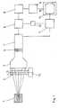
- a radiation source 1which can consist of an X-ray tube or a gamma emitter
- high-energy radiationis transmitted through a body 2 to be examined cleverly.
- the body 2is rotatably arranged on a manipulator 13.
- an X-ray image intensifier 3In the beam path of the radiation source 1 there is an X-ray image intensifier 3, the image of which reaches a television camera 5 via an optical system 4.
- This radiographic imagestrikes a screen 10 via an image processing device 7 and appears there as a conventional X-ray silhouette, which can be viewed in real time.
- this imageit can be determined by means of the image processing device 7 or by reading line markings 11, for which cross section of the body 2 a computer tomography measurement is to be carried out.
- a line selection device 12is arranged between the image processing device 7 and an image memory 6.
- the image points generated by the television camera 5are stored in this image memory 6 in two dimensions and in accordance with their gray values.
- the data for 512 to 1024 slice picturescan be stored in the picture memory at the same time.
- the measured values required for the computed tomographycan be determined and stored in the image memory 6. These measured values then arrive in a computer 8, are reconstructed there to form a slice image, passed to the television screen 10 via a further image memory 9 and displayed there.
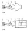
- the device shown in FIG. 3differs from that shown in FIGS. 1 and 2 only in that the radiographic image appears on an X-ray screen 14 and reaches the television camera 5 via an optic 15, a light amplifier 16 and another optic 4.
- the image processingtakes place in the same way as in the device according to FIGS. 1 and 2.
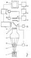
- the television camera 5is arranged perpendicular to the beam path of the X-ray image intensifier 3, so that the image falls into the television camera 5 when the Mirror 18 occupies the position shown.
- a position-resolving line detector 17is arranged in the beam path of the X-ray image intensifier 3 behind a further optical unit 21. If the mirror 18 is semitransparent, the mirrored image falls into the television camera 5, and the transmitted image onto the line detector 17. If the mirror 18 is opaque, it must be folded away by means of a rotating device 22 when the image of the X-ray image intensifier 3 is on the spatially resolving one Line detector 17 should fall.
- the manipulator 13 or the line detector 17Since the line detector 17 is only intended to detect one line at a time, ie is intended for recording a specific slice image, either the manipulator 13 or the line detector 17 must have a height adjustment device 19 or 20.
- the height adjustment device 19 or 20is connected to a line selection device 12 which is connected to the image processing device 7.
- the real-time radiation imagepasses through the X-ray image intensifier 3, the mirror 18, the television camera 5 and the image processing device 7 to the screen 10, while the computer tomographic layer image is generated via the line detector 17, the image memory 6, the computer 8 and the further image memory 9 and also is displayed on the screen 10.
- the layer imageis selected by means of the line selection device 12 in the same way as in the device according to FIG. 1.
Landscapes
- Health & Medical Sciences (AREA)
- Engineering & Computer Science (AREA)
- Multimedia (AREA)
- Nuclear Medicine, Radiotherapy & Molecular Imaging (AREA)
- Radiology & Medical Imaging (AREA)
- Physics & Mathematics (AREA)
- Life Sciences & Earth Sciences (AREA)
- Chemical & Material Sciences (AREA)
- Analytical Chemistry (AREA)
- Biochemistry (AREA)
- General Health & Medical Sciences (AREA)
- General Physics & Mathematics (AREA)
- Immunology (AREA)
- Pathology (AREA)
- Analysing Materials By The Use Of Radiation (AREA)
- Apparatus For Radiation Diagnosis (AREA)
Abstract
Description
Translated fromGermanDie Erfindung betrifft ein Verfahren und eine Vorrichtung zum Erzeugen eines Durchstrahlungsbildes mit einer auf einer Seite eines Körpers angeordneten Strahlenquelle für energiereiche Strahlung und einer auf der anderen Seite des Körpers angeordneten Aufnahmevorrichtung für das Durchstrahlungsbild, insbesondere zur Verwendung in der zerstörungsfreien Werkstoffprüfung.The invention relates to a method and a device for generating a radiographic image with a radiation source for high-energy radiation arranged on one side of a body and a receiving device for the radiographic image arranged on the other side of the body, in particular for use in non-destructive material testing.
Aus der DE-0S 35 20 600 ist eine Vorrichtung zur zerstörungsfreien Durchstrahlungsprüfung bekannt, bei der die Strahlen einer Röntgen- oder Gammastrahlenquelle ein zwischen der Strahlenquelle und einem Leuchtschirm angeordnetes Werkstück durchdringen und auf einem Leuchtschirm ein Strahlenbild erzeugen, das mittels einer Fernsehkettenübertragung auf einem Fernsehmonitor abgebildet wird. Das Durchstrahlungsbild wird in Echtzeit wiedergegeben und ist ein Schattenbild, das unterschiedlich dichte oder dicke Werkstoffe verschieden hell darstellt. Bei der zerstörungs freien Durchstrahlungsprüfung von Werkstücken kommen sehr häufig nebeneinanderliegende und sehr große Dickenunterschiede vor, beispielsweise bei Motorblöcken, Schweißnähten und anderen komplexen Bauteilen. Da in solchen, oft dicht nebeneinanderliegenden unterschiedlichen Wanddicken auch sehr kleine Fehler sichtbar gemacht werden müssen, ist der für das bildgebende System erforderliche Kontrastumfang sehr hoch. Wegen der häufig starken Dickenunterschiede innerhalb eines Bildes kommt es an den Stellen geringer Wanddicke oder bei fehlendem Material zu so starken Überstrahlungen, daß es einmal zu einer Beschädigung der Fernsehaufnahmeröhre kommen kann und daß zum anderen der technisch mögliche Kontrastumfang nicht ausreicht, um auch kleine Unterschiede, die auf kleine Fehler hindeuten, sichtbar zu machen. Es ist somit schwierig, zu einer schnellen und genau lokalisierenden Aussage über Fehler im Untersuchungsgut zu gelangen.From DE-0S 35 20 600 a device for non-destructive radiation testing is known, in which the rays of an X-ray or gamma radiation source penetrate a workpiece arranged between the radiation source and a luminescent screen and generate a radiation image on a luminescent screen, which is transmitted to a television monitor by means of a television chain transmission is mapped. The radiograph is reproduced in real time and is a shadow image that shows materials of different densities or thicknesses of different brightness. In the non-destructive radiation test of workpieces, there are very often large and very large differences in thickness, for example in the case of engine blocks, welds and other complex components. Because in such, often closely spaced, different wall thicknesses too If very small errors have to be made visible, the range of contrast required for the imaging system is very high. Because of the often large differences in thickness within an image, the areas of low wall thickness or the lack of material are so radiant that the television tube can be damaged and that the technically possible range of contrast is not sufficient to even small differences, that point to small mistakes to make visible. It is therefore difficult to arrive at a quick and precisely localizing statement about errors in the examination material.
Aus der DE-0S 32 24 964 sind ein Durchstrahlungsverfahren und eine Durchstrahlungsvorrichtung zum Materialprüfen bekannt, bei denen ein ortsauflösender Strahlendetektor und eine Strahlenquelle in einer durch die Strahlenquelle und den Strahlendetektor aufgespannten Ebene um eine dazu senkrechte Achse relativ zum Untersuchungsgut mittels eines drehbaren Objektträgers drehbar angeordnet sind. Bei jedem Drehwinkel wird die Ortsverteilung der Strahlungsintensität mit Hilfe einer Auswerteelektronik ermittelt. Auf diese Weise werden in einer dünnen Schicht, die durch die erwähnte, von der Strahlungsquelle und dem Strahlendetektor aufgespannten Ebene bestimmt ist, eine Vielzahl von Messungen in verschiedenen Winkelpositionen durchgeführt und dabei jeweils eine lineare Durchstrahlungsprojektion ermittelt. In einem Elektronenrechner werden diese verschiedenen Projektionen durch Logarithmierung, Faltungen und Entfaltungen in der aus der Computer-Tomographie bekannten Weise zum Erzeugen eines Schichtbildes des Untersuchungsguts verarbeitet und anschließend auf einem Bildschirm dargestellt oder anderweitig abgespeichert.From DE-0S 32 24 964 a radiation method and a radiation device for material testing are known, in which a spatially resolving radiation detector and a radiation source are arranged in a plane spanned by the radiation source and the radiation detector about a perpendicular axis relative to the examination material by means of a rotatable slide are. The local distribution of the radiation intensity is determined at each rotation angle with the aid of evaluation electronics. In this way, a multiplicity of measurements in different angular positions are carried out in a thin layer, which is determined by the plane spanned by the radiation source and the radiation detector, and a linear radiation projection is determined in each case. These various projections are processed in an electron computer by logarithmization, folding and unfolding in the manner known from computer tomography to produce a slice image of the examination subject and then displayed on a screen or otherwise stored.
Mit diesem Verfahren lassen sich dünne Materialschichten auf eine Strahlungsschwächung hin untersuchen und alle Einzelheiten des Schichtbildes mit hohem Auflösungsvermögen darstellen. Allerdings ist eine erhebliche Zeit erforderlich, um ein Schichtbild zu erzeugen, da jedesmal eine Drehung um 1 bis 2° erforderlich ist, bis ein Winkelbereich von mindestens 180° überschritten ist. Auch die Aufbereitung der Durchstrahlungswerte im Rechner erfordert verhältnismäßig viel Zeit, da die Rechenoperationen sehr aufwendig und kompliziert sind. Um einen sicherheitskritischen Körper vollständig zu untersuchen müssen Schichtbilder in Abständen von einigen Millimetern angefertigt werden, so daß die Computer-Tomographie bei der zerstörungsfreien Werkstoffprüfung nur in Sonderfällen angewandt wird.With this method, thin layers of material can be examined for radiation attenuation and all details of the layer image can be displayed with high resolution. However, a considerable time is required to generate a slice image, since a rotation of 1 to 2 ° is required each time until an angular range of at least 180 ° is exceeded. The processing of the radiographic values in the computer also requires a relatively large amount of time, since the computing operations are very complex and complex. In order to completely examine a safety-critical body, slice images must be made at intervals of a few millimeters, so that computer tomography is only used in special cases for non-destructive material testing.
Der Erfindung liegt die Aufgabe zugrunde, ein Verfahren und eine Vorrichtung zum Erzeugen eines Durchstrahlungsbildes zu schaffen, mit denen es möglich ist, einen Körper verhältnismäßig schnell und trotzdem mit großer Genauigkeit auf Fehler zu untersuchen.The invention has for its object to provide a method and an apparatus for generating a radiographic image, with which it is possible to examine a body relatively quickly and yet with great accuracy for errors.
Gelöst wird diese Aufgabe bei einer Vorrichtung der eingangs erwähnten Art erfindungsgemäß durch die Kombination einer Echtzeitwiedergabekette für das Durchstrahlungsbild mit einer Fernsehkamera, einem Bildschirm und einem Computer-Tomographen zum zeilenweisen Auswerten des Durchstrahlungsbildes und Darstellen eines Querschnitts des durchstrahlten Körpers auf dem Bildschirm.This object is achieved according to the invention in a device of the type mentioned at the outset by combining a real-time playback chain for the radiographic image with a television camera, a screen and a computer tomograph for line-by-line evaluation of the radiographic image and displaying a cross section of the irradiated body on the screen.
Mit dieser Kombination ist es möglich, zunächst auf dem Fernsehschirm das Durchstrahlungsbild des zu untersuchenden Körpers als Ganzes zu betrachten und dann die Schichten zu bestimmen, die mittels des Computer-Tomographen auf dem Bildschirm dargestellt werden sollen, um einen detailgenauen Querschnitt des zu untersuchenden Körpers zu liefern, in dem sich etwaige Fehler mit großer Genauigkeit erkennen lassen. Auf diese Weise wird die Anzahl der erforderlichen Schichtbilder auf das unbedingt notwendige Maß verringert und die Prüfung erheblich beschleunigt.With this combination it is possible to first view the radiograph of the body to be examined as a whole on the television screen and then to view the layers determine which are to be displayed on the screen by means of the computer tomograph in order to provide a detailed cross section of the body to be examined, in which any errors can be identified with great accuracy. In this way, the number of slice images required is reduced to the absolute minimum and the test is considerably accelerated.
Die Aufnahmevorrichtung für das Durchstrahlungsbild kann aus einem Röntgenbildverstärker und einer nachgeschalteten Fernsehkamera bestehen. Ebenso kann die Aufnahmevorrichtung für das Durchstrahlungsbild aus einem Röntgenbildschirm mit einem nachgeschalteten Lichtverstärker und einer Fernsehkamera bestehen.The recording device for the radiographic image can consist of an X-ray image intensifier and a television camera connected downstream. Likewise, the recording device for the radiographic image can consist of an X-ray screen with a light amplifier connected downstream and a television camera.
Zum Erstellen des Schichtbildes kann ein ortsauflösender Zeilendetektor im Strahlengang des Durchstrahlungsbildes angeordnet sein, wobei die Fernsehkamera und/oder der Zeilendetektor beweglich angeordnet sein können oder aber das Durchstrahlungsbild mittels eines beweglichen Spiegels auf die Fernsehkamera oder auf den Zeilendetektor gerichtet wird. Schließlich ist es auch möglich, einen halbdurchlässigen Spiegel im Strahlengang des Durchstrahlungsbildes anzuordnen und das durchgelassene oder das gespiegelte Bild auf die Fernsehkamera oder den Zeilendetektor zu lenken.To create the slice image, a position-resolving line detector can be arranged in the beam path of the transmission image, the television camera and / or the line detector can be arranged movably, or the transmission image can be directed onto the television camera or the line detector by means of a movable mirror. Finally, it is also possible to arrange a semitransparent mirror in the beam path of the transmission image and to direct the transmitted or the mirrored image onto the television camera or the line detector.
Wird ein ortsauflösender Zeilendetektor eingesetzt, um die Meßdaten für das Schichtbild zu liefern, sind entweder eine relativ zum Körper drehbare und höheneinstellbare Strahlenquelle und Aufnahmevorrichtung oder ein drehbarer und höheneinstellbarer Manipulator für den zu durchstrahlenden Körper oder ein drehbarer Manipulator für den zu durchstrahlenden Körper und eine Höheneinstellvorrichtung für den Zeilen detektor und die Strahlenquelle erforderlich, um den Körper relativ zur Strahlenquelle und zum Aufnahmesystem oder dem Zeilendetektor einzustellen. Vorzugsweise wird das Fernsehbild direkt verwendet, um die Meßwerte für den Computer-Tomographen zu liefern. Zu diesem Zweck ist hinter der Fernsehkamera ein Bildspeicher angeordnet, und der Computer-Tomograph ist zum zeilenweisen Auswerten des Bildes mit dem Bildspeicher verbunden. In diesem Falle braucht der zu untersuchende Körper mittels des Manipulators nur schrittweise gedreht zu werden, während von der Bedienperson eine gewünschte Zeile des Fernsehbildes ausgewählt und eingegeben wird, um hieraus das Schichtbild zu erzeugen.If a position-resolving line detector is used to provide the measurement data for the slice image, either a radiation source and recording device which can be rotated and adjusted in height relative to the body, or a rotatable and height-adjustable manipulator for the body to be irradiated or a rotatable manipulator for the body to be irradiated and a height adjustment device for the lines Detector and the radiation source required to adjust the body relative to the radiation source and the recording system or the line detector. The television image is preferably used directly to provide the measured values for the computer tomograph. For this purpose, an image memory is arranged behind the television camera and the computer tomograph is connected to the image memory for line-by-line evaluation of the image. In this case, the body to be examined need only be rotated step by step by means of the manipulator, while the operator selects and enters a desired line of the television picture in order to generate the slice picture therefrom.
Um eine bestimmte Schicht zur computer-tomographischen Darstellung eines Schichtbildes zu bestimmen, können auf dem Bildschirm Zeilenmarkierungen angeordnet sein, und eine ausgewählte Zeilenmarkierung kann dann in eine Zeilenwählvorrichtung eingegeben werden, die mit der Höheneinstellvorrichtung des Manipulators oder des Zeilendetektors oder der Strahlenquelle oder mit dem Bildspeicher verbunden ist.In order to determine a specific layer for the computer-tomographic representation of a layer image, line markings can be arranged on the screen, and a selected line marking can then be input into a line selection device which is operated with the height adjustment device of the manipulator or the line detector or the radiation source or with the image memory connected is.
Es ist aber auch möglich, eine rein elektronische Zeilenwählvorrichtung zu verwenden, wenn zwischen der Fernsehkamera und dem Bildschirm ein Bildverarbeitungsgerät angeordnet ist. In diesem Fall ist die Zeilenwählvorrichtung mit dem Bildverarbeitungsgerät und der Höheneinstellvorrichtung des Manipulators oder des Zeilendetektors oder mit dem Bildverarbeitungsgerät und dem Bildspeicher verbunden.However, it is also possible to use a purely electronic line selection device if an image processing device is arranged between the television camera and the screen. In this case, the line selection device is connected to the image processing device and the height adjustment device of the manipulator or the line detector or to the image processing device and the image memory.
Bei dem erfindungsgemäßen Verfahren zum Erzeugen eines Durchstrahlungsbildes eines Körpers wird mittels einer Echtzeitwiedergabekette ein Durchstrahlungsbild auf einem Bildschirm erzeugt, anhand des dargestellten Bildes eine Zeile zum Darstellen eines computer-tomographischen Schichtbildes gewählt und eingestellt sowie die computer-tomographische Messung durch schrittweises Drehen des Körpers durchgeführt. Die Meßwerte werden gespeichert, aufbereitet, und das Bild wird rekonstruiert und auf einem Bildschirm dargestellt. Vorzugsweise werden die Bildpunkte des Fernsehbildes in einem zwei-dimensionalen Bildspeicher gespeichert und die Bildpunkte jeder Zeile durch einen Computer-Tomographen zu einem Schichtbild dieser Zeile rekonstruiert.In the method according to the invention for generating a radiographic image of a body, a radiographic image is generated on a screen by means of a real-time display chain, based on the displayed image a line selected and set to display a computer-tomographic slice image and the computer-tomographic measurement was carried out by gradually rotating the body. The measured values are saved, processed, and the image is reconstructed and displayed on a screen. The pixels of the television picture are preferably stored in a two-dimensional image memory and the pixels of each line are reconstructed by a computer tomograph to form a layer image of this line.
Die Erfindung wird nachstehend anhand mehrerer in der Zeichnung dargestellter Ausführungsbeispiele des näheren erläutert. In der Zeichnung zeigen:
- Fig. 1 ein Funktionsschema der erfindungsgemäßen Vorrichtung mit einem Röntgenbildverstärker, einer nachgeschalteten Fernsehkamera und einer Seitenansicht des zu untersuchenden Körpers,
- Fig. 2 eine Draufsicht auf den Teil der Vorrichtung zum Erzeugen eines Durchstrahlungsbildes,
- Fig. 3 eine Draufsicht entsprechend Fig. 2 mit einem Röntgenbildschirm mit einem nachgeschalteten Lichtverstärker und einer Fernsehkamera und
- Fig. 4 ein Funktionsschema der erfindungsgemäßen Vorrichtung mit im Strahlengang angeordnetem ortsauflösenden Zeilendetektor.
- 1 is a functional diagram of the device according to the invention with an X-ray image intensifier, a downstream television camera and a side view of the body to be examined,
- 2 shows a plan view of the part of the device for generating a radiographic image,
- Fig. 3 is a plan view corresponding to FIG. 2 with an X-ray screen with a downstream light amplifier and a television camera and
- 4 shows a functional diagram of the device according to the invention with a spatially resolving line detector arranged in the beam path.
Mittels einer Strahlenquelle 1, die aus einer Röntgenröhre oder einem Gamma-Strahler bestehen kann, wird energiereiche Strahlung durch einen zu untersuchenden Körper 2 hindurch geschickt. Der Körper 2 ist drehbar auf einem Manipulator 13 angeordnet. Im Strahlengang der Strahlenquelle 1 befindet sich ein Röntgenbildverstärker 3 dessen Bild über eine Optik 4 in eine Fernsehkamera 5 gelangt. Dieses Durchstrahlungsbild trifft über ein Bildverarbeitungsgerät 7 auf einen Bildschirm 10 und erscheint dort als übliches Röntgenschattenbild, das sich in Echtzeit betrachten läßt.By means of a
In diesem Bild kann man mittels des Bildverarbeitungsgerätes 7 oder durch Ablesen von Zeilenmarkierungen 11 bestimmen, für welchen Querschnitt des Körpers 2 eine Computer-Tomographie-Messung durchgeführt werden soll. Zu diesem Zweck ist eine Zeilenwählvorrichtung 12 zwischen dem Bildverarbeitungsgerät 7 und einem Bildspeicher 6 angeordnet.In this image, it can be determined by means of the
In diesem Bildspeicher 6 werden die durch die Fernsehkamera 5 erzeugten Bildpunkte zweidimensional und entsprechend ihren Grauwerten gespeichert. Je nach Anzahl der Zeilen des Fernsehbildes lassen sich somit im Bildspeicher gleichzeitig die Daten für 512 bis 1024 Schichtbilder speichern. Durch Drehen des Körpers 2 mittels des Manipulators 13 jeweils um einen kleinen Winkel von 1 bis 2°, bis ein Winkelbereich von mindestens 180° überstrichen ist, lassen sich die für die Computer-Tomographie erforderlichen Meßwerte bestimmen und im Bildspeicher 6 abspeichern. Diese Meßwerte gelangen anschließend in einen Rechner 8, werden dort zum Schichtbild rekonstruiert, über einen weiteren Bildspeicher 9 zum Fernsehschirm 10 geleitet und dort dargestellt.The image points generated by the
Da durch die Fernsehkamera 5 schon ein zeilenweises Zerlegen des Bildes im Röntgenbildverstärker 3 erfolgt, ist nur eine Rotation des Körpers 2, nicht aber eine senkrechte Translation erforderlich.Since the
Die in Fig. 3 dargestellte Vorrichtung unterscheidet sich von der in Fig. 1 und 2 dargestellten nur insofern, als das Durchstrahlungsbild auf einem Röntgenbildschirm 14 erscheint und über eine Optik 15, einen Lichtverstärker 16 sowie eine weitere Optik 4 in die Fernsehkamera 5 gelangt. Die Bildaufbereitung geschieht in derselben Weise wie bei der Vorrichtung gemäß Fig. 1 und 2.The device shown in FIG. 3 differs from that shown in FIGS. 1 and 2 only in that the radiographic image appears on an
Bei der Vorrichtung gemäß Fig. 4 befindet sich im Anschluß an die Optik 4 hinter dem Röntgenbildverstärker 3 ein halbdurchlässiger oder beweglicher Spiegel 18. Die Fernsehkamera 5 ist senkrecht zum Strahlengang des Röntgenbildverstärkers 3 angeordnet, so daß das Bild in die Fernsehkamera 5 fällt, wenn der Spiegel 18 die dargestellte Lage einnimmt.4 there is a semitransparent or
Im Strahlengang des Röntgenbildverstärkers 3 ist hinter einer weiteren Optik 21 ein ortsauflösender Zeilendetektor 17 angeordnet. Falls der Spiegel 18 halbdurchlässig ist, fällt das gespiegelte Bild in die Fernsehkamera 5, und das durchgelassene Bild auf den Zeilendetektor 17. Falls der Spiegel 18 undurchlässig ist, muß er mittels einer Drehvorrichtung 22 weggeklappt werden, wenn das Bild des Röntgenbildverstärkers 3 auf den ortsauflösenden Zeilendetektor 17 fallen soll.A position-
Da der Zeilendetektor 17 jeweils nur eine Zeile erfassen soll, d.h. zur Aufnahme eines bestimmten Schichtbildes bestimmt ist, muß entweder der Manipulator 13 oder der Zeilendetektor 17 eine Höheneinstellvorrichtung 19 bzw. 20 aufweisen. Die Höheneinstellvorrichtung 19 oder 20 ist mit einer Zeilenwählvorrichtung 12 verbunden, die an das Bildverarbeitungsgerät 7 angeschlossen ist.Since the
Das Echtzeitdurchstrahlungsbild gelangt über den Röntgenbildverstärker 3, den Spiegel 18, die Fernsehkamera 5 und das Bildverarbeitungsgerät 7 zum Bildschirm 10, während das computer-tomographische Schichtbild über den Zeilendetektor 17, den Bildspeicher 6, den Rechner 8 und den weiteren Bildspeicher 9 erzeugt wird und ebenfalls auf dem Bildschirm 10 abgebildet wird.The real-time radiation image passes through the
Die Auswahl des Schichtbildes erfolgt mittels der Zeilenwählvorrichtung 12 in der gleichen Weise wie bei der Vorrichtung gemäß Fig. 1.The layer image is selected by means of the
Claims (15)
Translated fromGermanApplications Claiming Priority (2)
| Application Number | Priority Date | Filing Date | Title |
|---|---|---|---|
| DE3803129 | 1988-02-03 | ||
| DE3803129ADE3803129A1 (en) | 1988-02-03 | 1988-02-03 | METHOD AND DEVICE FOR GENERATING A TRANSMISSION IMAGE |
Publications (2)
| Publication Number | Publication Date |
|---|---|
| EP0326840A1true EP0326840A1 (en) | 1989-08-09 |
| EP0326840B1 EP0326840B1 (en) | 1990-11-14 |
Family
ID=6346505
Family Applications (1)
| Application Number | Title | Priority Date | Filing Date |
|---|---|---|---|
| EP89100650AExpired - LifetimeEP0326840B1 (en) | 1988-02-03 | 1989-01-16 | Method and apparatus for producing a radiation image |
Country Status (4)
| Country | Link |
|---|---|
| US (1) | US4975934A (en) |
| EP (1) | EP0326840B1 (en) |
| JP (1) | JPH01235839A (en) |
| DE (2) | DE3803129A1 (en) |
Cited By (1)
| Publication number | Priority date | Publication date | Assignee | Title |
|---|---|---|---|---|
| DE19817488A1 (en)* | 1998-04-20 | 1999-10-21 | Access Ev | Non-destructive test of body with partially porous region in metallic structure |
Families Citing this family (11)
| Publication number | Priority date | Publication date | Assignee | Title |
|---|---|---|---|---|
| US5648996A (en)* | 1995-08-04 | 1997-07-15 | Omega International Technology, Inc. | Tangential computerized tomography scanner |
| WO1999027857A1 (en)* | 1997-12-04 | 1999-06-10 | Hitachi Medical Corporation | X-ray examination apparatus and imaging method of x-ray image |
| RU2180958C2 (en)* | 1999-05-17 | 2002-03-27 | Тверской государственный технический университет | Gear to sort out metals and alloys |
| JP3987676B2 (en)* | 2000-07-10 | 2007-10-10 | 株式会社日立メディコ | X-ray measuring device |
| FR2820822B1 (en)* | 2001-02-14 | 2003-09-05 | Peugeot Citroen Automobiles Sa | DEVICE AND METHOD FOR HANDLING A PRODUCT AND PROCESSING RADIOCOSPIC IMAGES OF THE PRODUCT TO OBTAIN TOMOGRAPHIC CUTTINGS AND USES |
| JP4115675B2 (en)* | 2001-03-14 | 2008-07-09 | 三菱電機株式会社 | Absorption dosimetry device for intensity modulation therapy |
| CN101135656B (en)* | 2007-09-20 | 2010-06-23 | 中国特种设备检测研究院 | Pipe-pipe sheet weld joint non-destructive inspection system |
| JP5443100B2 (en)* | 2009-08-25 | 2014-03-19 | 富士フイルム株式会社 | Radiation image capturing apparatus, radiation image capturing system, and radiation image capturing method |
| JP6266574B2 (en)* | 2015-09-10 | 2018-01-24 | 株式会社日立ハイテクサイエンス | X-ray inspection method and X-ray inspection apparatus |
| JP7208636B2 (en)* | 2017-10-20 | 2023-01-19 | 国立大学法人千葉大学 | Tomography device |
| JP6779535B2 (en)* | 2019-04-24 | 2020-11-04 | 国立大学法人千葉大学 | Reflective tomography equipment |
Citations (6)
| Publication number | Priority date | Publication date | Assignee | Title |
|---|---|---|---|---|
| US4030119A (en)* | 1975-10-01 | 1977-06-14 | General Electric Company | Video window control |
| EP0098398A2 (en)* | 1982-07-03 | 1984-01-18 | Kurt Dr. Sauerwein | Radiographic method and device for material testing |
| DE8307020U1 (en)* | 1983-03-11 | 1984-08-16 | Sauerwein, Kurt, Dr., 5657 Haan | DEVICE FOR NON-DESTRUCTIVE RADIATION TESTING WITH X-RAY OR GAMMA OR Gamma RAYS |
| EP0205825A1 (en)* | 1985-06-08 | 1986-12-30 | Isotopen-Technik Dr. Sauerwein Gmbh | Method and device for non-destructive radiographic testing |
| EP0234922A2 (en)* | 1986-02-24 | 1987-09-02 | Exxon Research And Engineering Company | Producing tomographic images |
| EP0263080A2 (en)* | 1986-10-01 | 1988-04-06 | Ente per le nuove tecnologie, l'energia e l'ambiente (ENEA) | A method and apparatus for the automatic radiograpgicreal-time analysis of articles, in particular for pipe-plug weldings |
Family Cites Families (2)
| Publication number | Priority date | Publication date | Assignee | Title |
|---|---|---|---|---|
| DE2613809B2 (en)* | 1976-03-31 | 1979-01-04 | Siemens Ag, 1000 Berlin Und 8000 Muenchen | X-ray layer device for the production of transverse layer images |
| NL7605253A (en)* | 1976-05-17 | 1977-11-21 | Optische Ind De Oude Delft Nv | DEVICE FOR TOMOGRAPHY. |
- 1988
- 1988-02-03DEDE3803129Apatent/DE3803129A1/ennot_activeWithdrawn
- 1989
- 1989-01-16DEDE8989100650Tpatent/DE58900024D1/ennot_activeExpired - Fee Related
- 1989-01-16EPEP89100650Apatent/EP0326840B1/ennot_activeExpired - Lifetime
- 1989-01-17USUS07/298,038patent/US4975934A/ennot_activeExpired - Fee Related
- 1989-01-31JPJP1022463Apatent/JPH01235839A/enactivePending
Patent Citations (6)
| Publication number | Priority date | Publication date | Assignee | Title |
|---|---|---|---|---|
| US4030119A (en)* | 1975-10-01 | 1977-06-14 | General Electric Company | Video window control |
| EP0098398A2 (en)* | 1982-07-03 | 1984-01-18 | Kurt Dr. Sauerwein | Radiographic method and device for material testing |
| DE8307020U1 (en)* | 1983-03-11 | 1984-08-16 | Sauerwein, Kurt, Dr., 5657 Haan | DEVICE FOR NON-DESTRUCTIVE RADIATION TESTING WITH X-RAY OR GAMMA OR Gamma RAYS |
| EP0205825A1 (en)* | 1985-06-08 | 1986-12-30 | Isotopen-Technik Dr. Sauerwein Gmbh | Method and device for non-destructive radiographic testing |
| EP0234922A2 (en)* | 1986-02-24 | 1987-09-02 | Exxon Research And Engineering Company | Producing tomographic images |
| EP0263080A2 (en)* | 1986-10-01 | 1988-04-06 | Ente per le nuove tecnologie, l'energia e l'ambiente (ENEA) | A method and apparatus for the automatic radiograpgicreal-time analysis of articles, in particular for pipe-plug weldings |
Non-Patent Citations (1)
| Title |
|---|
| PATENT ABSTRACTS OF JAPAN* |
Cited By (1)
| Publication number | Priority date | Publication date | Assignee | Title |
|---|---|---|---|---|
| DE19817488A1 (en)* | 1998-04-20 | 1999-10-21 | Access Ev | Non-destructive test of body with partially porous region in metallic structure |
Also Published As
| Publication number | Publication date |
|---|---|
| DE58900024D1 (en) | 1990-12-20 |
| EP0326840B1 (en) | 1990-11-14 |
| JPH01235839A (en) | 1989-09-20 |
| DE3803129A1 (en) | 1989-08-17 |
| US4975934A (en) | 1990-12-04 |
Similar Documents
| Publication | Publication Date | Title |
|---|---|---|
| EP1749190B1 (en) | Method for measuring an object using a coordinate measuring machine including a computer tomograph | |
| EP1380263B1 (en) | Process and device for measuring the actual position of the structure of an object to be examined | |
| DE3510692C2 (en) | ||
| DE19950793B4 (en) | X-ray device and method for determining imaging parameters | |
| DE3937559C2 (en) | ||
| DE102007016370A1 (en) | Method and a measuring arrangement for generating three-dimensional images of test objects by means of invasive radiation | |
| EP0326840B1 (en) | Method and apparatus for producing a radiation image | |
| DE3689166T2 (en) | Substance quantification in carcasses. | |
| DE102004026357A1 (en) | Coordinate measuring and object scanning system uses X-ray source and X-ray sensors for primary scan and tactile and/or optical secondary mechanism movable in X, Y and Z directions for secondary scan | |
| DE10354899A1 (en) | X-ray set-up, e.g. for generating x-ray image data set, has source of x-ray and x-ray detector for production of first radiograph data record of investigation object with second x-ray detector | |
| DE3150306A1 (en) | Method and device for inspecting objects, in particular pieces of luggage for target contents | |
| EP0057957B1 (en) | Arrangement for non medical examination of a body | |
| DE10202732A1 (en) | Device and method for creating a correction characteristic for reducing artifacts in a tomography | |
| DE102007043820B4 (en) | Method for determining a correction value of a brake spot position of an X-ray source of a measuring arrangement and a measuring arrangement for generating radiographic images | |
| DE2831311C2 (en) | Device for determining internal body structures by means of scattered radiation | |
| DE102004033526A1 (en) | Analysis of at least partly reflecting surfaces involves varying relative orientation/position of object, pattern generation device and/or image receiver(s) for image reflected at surface, to obtain surface, especially geometry, information | |
| DE3037169C2 (en) | ||
| DE3120567A1 (en) | SCREEN BEAM EXAMINATION ARRANGEMENT | |
| DE102021206401A1 (en) | Computed tomography arrangement and method for operating a computed tomography arrangement | |
| DE1936937A1 (en) | Method for testing optical specimens and optical bench for carrying out the method | |
| EP0098398A2 (en) | Radiographic method and device for material testing | |
| DE102004039681A1 (en) | Tomography device and method for a tomography device | |
| DE102022103888A1 (en) | Method and device for computed tomography measurement | |
| EP0959344B1 (en) | Method and assembly for carrying out irradiation tests on units | |
| DE102007045798A1 (en) | Arrangement for recording X-ray and / or gamma-ray scattering images |
Legal Events
| Date | Code | Title | Description |
|---|---|---|---|
| PUAI | Public reference made under article 153(3) epc to a published international application that has entered the european phase | Free format text:ORIGINAL CODE: 0009012 | |
| AK | Designated contracting states | Kind code of ref document:A1 Designated state(s):DE FR GB | |
| 17P | Request for examination filed | Effective date:19890819 | |
| 17Q | First examination report despatched | Effective date:19900403 | |
| RAP1 | Party data changed (applicant data changed or rights of an application transferred) | Owner name:ISOTOPEN-TECHNIK DR. SAUERWEIN GMBH | |
| GRAA | (expected) grant | Free format text:ORIGINAL CODE: 0009210 | |
| AK | Designated contracting states | Kind code of ref document:B1 Designated state(s):DE FR GB | |
| GBT | Gb: translation of ep patent filed (gb section 77(6)(a)/1977) | ||
| REF | Corresponds to: | Ref document number:58900024 Country of ref document:DE Date of ref document:19901220 | |
| ET | Fr: translation filed | ||
| PLBE | No opposition filed within time limit | Free format text:ORIGINAL CODE: 0009261 | |
| STAA | Information on the status of an ep patent application or granted ep patent | Free format text:STATUS: NO OPPOSITION FILED WITHIN TIME LIMIT | |
| 26N | No opposition filed | ||
| PGFP | Annual fee paid to national office [announced via postgrant information from national office to epo] | Ref country code:GB Payment date:19971230 Year of fee payment:10 | |
| PGFP | Annual fee paid to national office [announced via postgrant information from national office to epo] | Ref country code:FR Payment date:19980119 Year of fee payment:10 | |
| PGFP | Annual fee paid to national office [announced via postgrant information from national office to epo] | Ref country code:DE Payment date:19980323 Year of fee payment:10 | |
| PG25 | Lapsed in a contracting state [announced via postgrant information from national office to epo] | Ref country code:GB Free format text:LAPSE BECAUSE OF NON-PAYMENT OF DUE FEES Effective date:19990116 | |
| GBPC | Gb: european patent ceased through non-payment of renewal fee | Effective date:19990116 | |
| PG25 | Lapsed in a contracting state [announced via postgrant information from national office to epo] | Ref country code:FR Free format text:LAPSE BECAUSE OF NON-PAYMENT OF DUE FEES Effective date:19990930 | |
| PG25 | Lapsed in a contracting state [announced via postgrant information from national office to epo] | Ref country code:DE Free format text:LAPSE BECAUSE OF NON-PAYMENT OF DUE FEES Effective date:19991103 | |
| REG | Reference to a national code | Ref country code:FR Ref legal event code:ST |