EP0325186B1 - Shut-off device for closing synthetic tubes, especially infusion tubes, for air traps - Google Patents
Shut-off device for closing synthetic tubes, especially infusion tubes, for air trapsDownload PDFInfo
- Publication number
- EP0325186B1 EP0325186B1EP19890100653EP89100653AEP0325186B1EP 0325186 B1EP0325186 B1EP 0325186B1EP 19890100653EP19890100653EP 19890100653EP 89100653 AEP89100653 AEP 89100653AEP 0325186 B1EP0325186 B1EP 0325186B1
- Authority
- EP
- European Patent Office
- Prior art keywords
- hose
- air trap
- blocking device
- accordance
- pressure
- Prior art date
- Legal status (The legal status is an assumption and is not a legal conclusion. Google has not performed a legal analysis and makes no representation as to the accuracy of the status listed.)
- Expired - Lifetime
Links
- 238000001802infusionMethods0.000titleclaimsabstractdescription9
- 239000012528membraneSubstances0.000claimsabstractdescription13
- 230000000903blocking effectEffects0.000claimsdescription12
- 239000004033plasticSubstances0.000claimsdescription8
- 230000004888barrier functionEffects0.000claimsdescription4
- 239000007788liquidSubstances0.000claimsdescription2
- 238000013022ventingMethods0.000claimsdescription2
- 230000002093peripheral effectEffects0.000claims2
- 230000002146bilateral effectEffects0.000claims1
- 230000000284resting effectEffects0.000claims1
- 239000008280bloodSubstances0.000abstractdescription4
- 210000004369bloodAnatomy0.000abstractdescription4
- 239000004809TeflonSubstances0.000abstractdescription2
- 229920006362Teflon®Polymers0.000abstractdescription2
- 230000036770blood supplyEffects0.000abstract1
- 239000007789gasSubstances0.000description15
- 230000006835compressionEffects0.000description3
- 238000007906compressionMethods0.000description3
- QVGXLLKOCUKJST-UHFFFAOYSA-Natomic oxygenChemical compound[O]QVGXLLKOCUKJST-UHFFFAOYSA-N0.000description2
- 230000000694effectsEffects0.000description2
- 239000001301oxygenSubstances0.000description2
- 229910052760oxygenInorganic materials0.000description2
- 241000272814Anser sp.Species0.000description1
- FYYHWMGAXLPEAU-UHFFFAOYSA-NMagnesiumChemical group[Mg]FYYHWMGAXLPEAU-UHFFFAOYSA-N0.000description1
- CBENFWSGALASAD-UHFFFAOYSA-NOzoneChemical compound[O-][O+]=OCBENFWSGALASAD-UHFFFAOYSA-N0.000description1
- 238000011161developmentMethods0.000description1
- 230000018109developmental processEffects0.000description1
- 239000003978infusion fluidSubstances0.000description1
- 238000009434installationMethods0.000description1
- 238000005259measurementMethods0.000description1
- 238000012544monitoring processMethods0.000description1
- 230000002485urinary effectEffects0.000description1
Images

Classifications
- A—HUMAN NECESSITIES
- A61—MEDICAL OR VETERINARY SCIENCE; HYGIENE
- A61M—DEVICES FOR INTRODUCING MEDIA INTO, OR ONTO, THE BODY; DEVICES FOR TRANSDUCING BODY MEDIA OR FOR TAKING MEDIA FROM THE BODY; DEVICES FOR PRODUCING OR ENDING SLEEP OR STUPOR
- A61M39/00—Tubes, tube connectors, tube couplings, valves, access sites or the like, specially adapted for medical use
- A61M39/22—Valves or arrangement of valves
- A61M39/28—Clamping means for squeezing flexible tubes, e.g. roller clamps
- A61M39/281—Automatic tube cut-off devices, e.g. squeezing tube on detection of air
- A—HUMAN NECESSITIES
- A61—MEDICAL OR VETERINARY SCIENCE; HYGIENE
- A61M—DEVICES FOR INTRODUCING MEDIA INTO, OR ONTO, THE BODY; DEVICES FOR TRANSDUCING BODY MEDIA OR FOR TAKING MEDIA FROM THE BODY; DEVICES FOR PRODUCING OR ENDING SLEEP OR STUPOR
- A61M39/00—Tubes, tube connectors, tube couplings, valves, access sites or the like, specially adapted for medical use
- A61M39/22—Valves or arrangement of valves
- A61M39/28—Clamping means for squeezing flexible tubes, e.g. roller clamps
- Y—GENERAL TAGGING OF NEW TECHNOLOGICAL DEVELOPMENTS; GENERAL TAGGING OF CROSS-SECTIONAL TECHNOLOGIES SPANNING OVER SEVERAL SECTIONS OF THE IPC; TECHNICAL SUBJECTS COVERED BY FORMER USPC CROSS-REFERENCE ART COLLECTIONS [XRACs] AND DIGESTS
- Y10—TECHNICAL SUBJECTS COVERED BY FORMER USPC
- Y10T—TECHNICAL SUBJECTS COVERED BY FORMER US CLASSIFICATION
- Y10T137/00—Fluid handling
- Y10T137/8158—With indicator, register, recorder, alarm or inspection means
- Y10T137/8175—Plural
Definitions
- the inventionconsists of an air trap for blocking plastic hoses, in particular infusion hoses with the features specified in the preamble of claim 1.
- a shut-off device for plastic hoseswhich has a membrane in a pressure chamber which actuates a reciprocating plunger.
- a pistonis arranged below the diaphragm and connected to the tappet and can be moved back and forth in a cylinder.
- the pistonis pressed out of the cylinder against a spring effect and the tappet clamps off a hose. If there is no pressure in the cylinder chamber, the plunger with piston is pressed down into the cylinder chamber due to the spring action. releasing the hose.
- a disadvantage of this air trap known from DE-A-34 35 781is that in the event of a pressure drop in the cylinder space, the clamping effect is eliminated.
- EP-A-0 150 666discloses a closure on a urinary catheter in which the closure is normally closed under spring action. This is achieved in that the closure has a reciprocating plunger which clamps a hose by spring action. The plunger is operated manually. With manual pressure, the hose passage is released and with manual pressure relief, it is clamped by the plunger under spring action.
- the closure known from EP-A-0 150 666means that it cannot be switched off automatically. Furthermore, the functionality of the closure can result from fatigue fracture or. Wear of the springs can be at risk.
- the present inventionis therefore based on the object of developing the known device for shutting off plastic hoses in such a way that a safe and reliable clamping action is automatically achieved in use for an air trap in emergencies.
- the air trap according to the invention for shutting off plastic hoses, in particular infusion hosesis characterized in that compression springs are provided which engage the plunger and each have a switching current flowing through them, and if at least one spring breaks, this interrupts the switching current and thus blocks the gas inlet.
- the pressure chamber 1is formed by the two interconnected housing parts 2 and 3, in particular made of plastic with a recess 4 in which a plate-shaped membrane 5, for example as a Teflon membrane, is clamped.
- This membrane 5rests on the one hand against the title block 6, while on the other hand the recess bottom 7 with the pressure line connection 8 lies.
- the title block 6is seated on two compression springs 9a, 9b which are concentrically arranged one inside the other and which are preferably opposed to one another, e.g. are isolated by means of an insulating spiral 10 and flowed through by a switching current 11, as a result of which this is interrupted when the spring breaks and the pressure line connection 8 is thus blocked, as will be described later.
- the title block 6extends with its guide plunger 12 through a sleeve 14 seated on a housing cover 13, which serves as a passage 17 through bulges 15 for a plastic hose 16 and closes the same (17) by means of encirclement 18 as long as the pressure chamber 1 is not under gas pressure.
- the sleeve 14is fastened to the housing cover 13 or with it in one piece and has a crosspiece 19 in the center with bulges 15 as a tube passage 17 on both sides, which together with a wrap 18 and slot 18a for the crosspiece 19 causes a hose clamp 20.
- a light barrier(not shown) is provided on both sides of the tube passage 17, which are open when liquid, such as blood, flows through the tube 16 and close when air bubbles pass through and open a current switch 22 via a controller (not shown here).
- Conventional brackets for hose installation and removalare provided on both sides of the hose passage 17, as is not particularly shown here.
- the opening of the air trapi.e. the tube passage 17 of the plastic tube 16 on the wrap 18 takes place against the action of the spring 9a, 9b when the diaphragm head 5 is acted upon by a membrane 5 through a gas inlet (at 8).
- Thisis controlled by a three-way valve 25, in which a magnetic core 27, a goose inlet 28, e.g. of an oxygen pressure bottle and passage 29 to the gas inlet 8 for the pressure chamber 1 opens and closes when the power is interrupted and opens a gas outlet 30 to the atmosphere.
- the magnetic core 27is under the action of a spring 31, so that when the current is interrupted on the coil 26, it blocks the passage (gas inlet) 29 with additional securing by its own weight and opens the gas outlet 30 to the atmosphere, as is shown schematically in the drawing according to Figure 3 is shown.
- the gas inlet 28is throttled relative to the passage 29 and gas outlet 30 at 32, so that when the spring 31 is broken, the gas flow is throttled to such an extent that the pressure in the line due to the induced pneumatic resistance is insufficient to open the air trap or at Switching off the solenoid valve, the existing excess pressure can be vented through the gas outlet 30 with the inflowing gas from line 28 against the atmosphere.
- the weight of the magnetic core 27is to be selected to be greater than the pneumatic contact force to the gas outlet 30.
- a further reflection light barrier 33can be controlled from the surface 6a of the title block 6 and passes between the throttled (32) gas inlet 28 when the magnesium core 27 is actuated by energizing the coil 26 and filling the pressure chamber 1 by actuating the other Membrane 5 of the facing head 6 against the action of the spring 9a, 9b until the hose passage 17 of the air trap is fully opened by means of a grip 18 for a predetermined time. If the time falls below this predetermined time, then the springs 9a, 9b or one of them are either weakened or broken and the disconnection at the hose passage 17 is in this case made by a corresponding time measurement comparison control by venting the pressure chamber 1, for example by switching off the current on the coil 26 causes.
- This arrangementcan be installed in addition to the current continuity monitoring of the springs 9a, 9b, as described above, for the functional safety of the air trap.
- this air trapoperates at lower pressures; otherwise the overall arrangement can be made flatter with correspondingly shorter compression springs than shown in the drawing.
Landscapes
- Health & Medical Sciences (AREA)
- Heart & Thoracic Surgery (AREA)
- Pulmonology (AREA)
- Engineering & Computer Science (AREA)
- Anesthesiology (AREA)
- Biomedical Technology (AREA)
- Hematology (AREA)
- Life Sciences & Earth Sciences (AREA)
- Animal Behavior & Ethology (AREA)
- General Health & Medical Sciences (AREA)
- Public Health (AREA)
- Veterinary Medicine (AREA)
- Infusion, Injection, And Reservoir Apparatuses (AREA)
Abstract
Description
Translated fromGermanDie Erfindung besteht aus von einer Luftfalle zur Absperrung von Kunsstoffschläuchen, insbesondre Infusionschläuchen mit den im Oberbegriff des Anspruchs 1 angegebenen Merkmalen.The invention consists of an air trap for blocking plastic hoses, in particular infusion hoses with the features specified in the preamble of
Es sind Luftfallen für diese Zwecke mit Schlauchabklemmung vermittels gegen Federwirkung kolbengeführten Druckbolzen bekannt, welche dafür sorgen sollen, daß bei Infusionen beim Ausgehen der Infusionsflüssigkeit oder anderen Störungen, wenn diese unter Druck der Blutbahn des Patienten zugeführt wird, unterbrochen wird, sobald Luftblasen folgen, damit diese nicht in die Blutbahn gedrückt werden, was zum Tod des Patienten führen würde. So wird beispielsweise mit Ozon angereichertes Patientenblut unter Sauerstoffdruck aus der Blutinfusionsflasche in die Blutbahn des Patienten zurückgeführt.There are air traps for this purpose with hose clamping by means of spring-loaded piston-operated pressure bolts, which are intended to ensure that in the case of infusions when the infusion liquid comes out or other disturbances, if this is supplied to the patient's bloodstream under pressure, are interrupted as soon as air bubbles follow, thus these are not pressed into the bloodstream, which would lead to the death of the patient. For example, patient blood enriched with ozone is returned from the blood infusion bottle into the patient's bloodstream under oxygen pressure.
Durch die DE-A-34 35 781 ist eine Abspereinrichtung für Kunststoffschläuche bekannt, welche in einer Druckkammer eine Membrane aufweist, die einen hin- und herbewegbaren Stößel betätigt. Unterhalb der Membrane und mit dem Stößel verbunden ist ein Kolben angeordnet, welcher in einem Zylinder hin- und herbewegbar ist. Bei einer Druckbeaufschlagung des Zylinderraums wird der Kolben gegen eine Federwirkung aus dem Zylinder herausgedrückt und der Stößel klemmt dabei einen Schlauch ab. Liegt im Zylinderraum kein Druck an, so wird der stößel mit Kolben aufgrund der Federwirkung in den Zylinderraum hinuntergedrückt, wobei der Schlauch freigegeben wird. Nachteilig bei dieser durch die DE-A-34 35 781 bekannten Luftfalle ist, daß im Falle eines Druckabfalls im Zylinderraum die Klemmwirkung aufgehoben wird.From DE-A-34 35 781 a shut-off device for plastic hoses is known which has a membrane in a pressure chamber which actuates a reciprocating plunger. A piston is arranged below the diaphragm and connected to the tappet and can be moved back and forth in a cylinder. When the cylinder chamber is pressurized, the piston is pressed out of the cylinder against a spring effect and the tappet clamps off a hose. If there is no pressure in the cylinder chamber, the plunger with piston is pressed down into the cylinder chamber due to the spring action. releasing the hose. A disadvantage of this air trap known from DE-A-34 35 781 is that in the event of a pressure drop in the cylinder space, the clamping effect is eliminated.
Desweiteren ist durch die EP-A-0 150 666 ein Verschluß an einem Harnkatheder bekannt, bei dem der Verschluß unter Federwirkung normalerweise geschlossen ist. Dies wird dadurch erzielt, daß der Verschluß einen hin- und herbewegbaren Stößel aufweist, welcher durch Federwirkung einen Schlauch abklemmt. Der Stößel wird hierbei manuell betätigt. Bei manuellem Druck wird der Schlauchdurchgang freigegeben und bei manueller Druckentlastung wird er durch den Stößel unter Federwirkung abgeklemmt.Furthermore, EP-A-0 150 666 discloses a closure on a urinary catheter in which the closure is normally closed under spring action. This is achieved in that the closure has a reciprocating plunger which clamps a hose by spring action. The plunger is operated manually. With manual pressure, the hose passage is released and with manual pressure relief, it is clamped by the plunger under spring action.
Bedingt durch die manuelle Betätigung kann durch den aus der EP-A-0 150 666 bekannten Verschluß keine selbsttätige Abschaltung erfolgen. Desweiteren kann die Funktionsfähigkeit des Verschlusses infolge von Ermüdungsbruch oder. Verschleiß der Federn gefährdet sein kann.Due to the manual actuation, the closure known from EP-A-0 150 666 means that it cannot be switched off automatically. Furthermore, the functionality of the closure can result from fatigue fracture or. Wear of the springs can be at risk.
Der vorliegenden Erfindung liegt daher die Aufgabe zugrunde, die bekannte Einrichtung zur Absperrung von Kunststoffschläuchen so weiterzubilden, daß in Verwendung für eine Luftfalle in Notfällen selbsttätig eine sichere und zuverlässige Klemmwirkung erzielt wird .The present invention is therefore based on the object of developing the known device for shutting off plastic hoses in such a way that a safe and reliable clamping action is automatically achieved in use for an air trap in emergencies.
Diese Aufgabe wird durch die Merkmale des Anspruchs 1 gelöst. Vorteilhafte Weiterbildungen sind Gegenstand der Unteransprüche.This object is solved by the features of
Die erfindungsgemäße Luftfalle zur Absperrung von Kunststoffschläuchen, insbesondere Infustionsschläuchen zeichnet sich dadurch aus, daß am Stößel angreifende, jeweils mit einem Schaltstrom durchflossene Druckfedern vorgesehen sind, wobei beim Bruch wenigstens einer Feder diese den Schaltstrom unterbricht und damit den Gaseinlaß sperrt. Dies hat den Vorteil, daß bei Ermüdung oder beim Bruch einer Feder stets sichergestellt wird, daß der Gaseinlaß gesperrt wird, wodurch eine selbsttätige Abschaltung vollzogen wird.The air trap according to the invention for shutting off plastic hoses, in particular infusion hoses, is characterized in that compression springs are provided which engage the plunger and each have a switching current flowing through them, and if at least one spring breaks, this interrupts the switching current and thus blocks the gas inlet. This has the advantage that it always ensures that the gas inlet is blocked in the event of fatigue or when a spring breaks, as a result of which an automatic shutdown is carried out.
In der Zeichnung ist beispielsweise eine bevorzugte Ausführungsform der erfindungsgemäßen Luftfalle dargestellt und nachfolgend beschrieben und zwar zeigen:
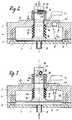
Figur 1- einen Schnitt durch eine Luftfalle beim öffnen,
Figur 2- einen Schnitt der Luftfalle nach
Figur 1 in geschlossener Stellung und Figur 3- einen Schnitt durch eine Desamtanordnung.
- Figure 1
- a cut through an air trap when opening,
- Figure 2
- a section of the air trap of Figure 1 in the closed position and
- Figure 3
- a section through a velvet arrangement.
Wie aus der Zeichnung Fig. 1 und 2 ersichtlich ist, wird die Druckkammer 1 gebildet durch die beiden miteinander verbundenen Gehäuseteile 2 und 3, insbes. aus Kunststoff mit eingebrachter Ausnehmung 4, in welcher eine tellerförmige Membrane 5, z.B. als Teflonmembrane eingespannt ist. Dieser Membrane 5 liegt einerseits der Plankopf 6 an, während andererseits der Ausnehmungsboden 7 mit Druckleitungsanschluß 8 liegt.As can be seen from the drawing of FIGS. 1 and 2, the
Der Plankopf 6 sitzt auf zwei konzentrisch ineinanderliegenden Druckfedern 9a, 9b, welche vorzugsweise gegeneinander, z.,B. mittels Isolierspirale 10, isoliert und durch einen Schaltstrom 11 durchflossen sind, wodurch dieser bei Federbruch unterbrochen und damit der Druckleitungsanschluß 8 gesperrt wird, wie dies später geschildert ist.The
Der Plankopf 6 reicht mit seinem Führungsstößel 12 durch eine einem Gehäusedeckel 13 aufsitzende Hülse 14, welche durch Einwölbungen 15 für einen Kunststoffschlauch 16 als Durchgang 17 dient und mittels Umgriff 18 denselben (17) verschließt, solange die Druckkammer 1 nicht unter Gasdruck steht. Die Hülse 14 ist auf dem Gehäusedeckel 13 befestigt oder auch mit diesem aus einem Stück und weist mit beidseitigen Einwölbungen 15 als Schlauchdurchgang 17 mittig einen Quersteg 19 auf, welcher zusammen mit einem Umgriff 18 und Schlitzung 18a für den Quersteg 19 eine Schlauchabklemmung 20 bewirkt.The
Es ist beidseits des Schlauchdurchgangs 17 je eine Lichtschranke (nicht dargestellt) vorgesehen, welche bei im Schlauch 16 durchlaufender Flüssigkeit, wie Blut geöffnet sind und bei Durchtritt von Luftblasen schließen und dabei über eine hier nicht dargestellte Steuerung einen Stromschalter 22 öffnen.
Beidseits am Schlauchdurchgang 17 sind übliche Halterungen zur Schlauchanlage und -entnahme vorgesehen, wie dies hier nicht besondres dargestellt ist.A light barrier (not shown) is provided on both sides of the
Conventional brackets for hose installation and removal are provided on both sides of the
Die Öffnung der Luftfalle, d.h. des Schlauchdurchgangs 17 des Kunststoffschlauchs 16 am Umgriff 18 erfolgt gegen die Wirkung der Feder 9a, 9b bei Beaufschlagung des Plankopfes 6 mit Membran 5 durch Gaseinlaß (bei 8). Dieser wird durch ein Dreiwegeventil 25 gesteuert, bei welchem bei Bestromung einer Spule 26 ein Magnetkern 27 einen Ganseingang 28, z.B. von einer Sauerstoffdruckflasche und Durchgang 29 zum Gaseinlaß 8 für die Druckkammer 1 öffnet und bei Stromunterbrechung schließt und einen Gasausgang 30 zur Atmosphäre öffnet. Hierfür steht der Magnetkern 27 unter Wirkung einer Feder 31, so daß er bei Stromunterbrechung an der Spule 26 die Sperrung des Durchgangs (Gaseingangs) 29 unter zusätzlicher Sicherung durch sein Eigengewicht bewirkt und den Gasausgang 30 zur Atmosphäre hin öffnet, wie dies schematisch in der Zeichnung nach Figur 3 dargestellt ist. Im übrigen ist der Gaseingang 28 gegenüber dem Durchgang 29 und Gasausgang 30 bei 32 gedrosselt, damit bei gebrochener Feder 31 der Gasstrom soweit gedrosselt wird, daß der Überdruck in der Leitung durch den induzierten pneumatischen Widerstand nicht ausreicht, um die Luftfalle zu öffnen bzw. beim Abschalten des Magnetventils der vorhandene Überdruck durch den Gasausgang 30 mit dem zuströmenden Gas aus Leitung 28 gegen die Atmosphäre entlüftet werden kann. Das Eigengewicht des Magnetkerns 27 is dabei größer zu wählen als die pneumatische Anpreßkraft zum Gasausgang 30.The opening of the air trap, i.e. the
Eine weitere Reflektions-Lichtschranke 33 kann von der Oberfläche 6a des Plankopfes 6 gesteuert werden und zwar vergeht zwischen dem gedrosselten (32) Gaseingang 28 bei Betätigung des Mgnetkerns 27 durch Bestromung der Spule 26 und dem Füllen der Druckkammer 1 mit Betätigung des an der Membrane 5 anliegenden Plankopfes 6 gegen Wirkung der Feder 9a, 9b bis zum vollen öffnen des Schlauchdurchgangs 17 der Luftfalle mittels Umgriff 18 eine vorbestimmte Zeit. Wird nun diese vorgegebene Zeit unterschritten, so sind die Federn 9a, 9b bzw. eine hiervon entweder erlahmt oder gebrochen und die Abklemmung am Schlauchdurchgang 17 wird in diesem Falle durch eine entsprechende Zeitmeß-Vergleichssteuerung durch Entlüftung der Druckkammer 1, z.B. über Stromabschaltung an der Spule 26 bewirkt. Diese Anordnung kann zusätzlich zu der Stromdurchgangsüberwachung der Federn 9a, 9b, wie vorgeschildert, zur Funktionssicherheit der Luftfalle eingebaut werden.A further
Zufolge des großflächigen Plankopfs 6 arbeitet diese Luftfalle mit geringeren Drücken; im übrigen läßt sich die Gesamtanordnung bei entspr. kürzeren Druckfedern flacher bauen als in der Zeichnung dargestellt.Due to the large-
Claims (9)
- Blocking device for plastic hoses, in particular infusion hoses, with a casing (2, 3) in which a pressure chamber (1) is provided, in which there is a membrane (5) and which is supplied with gas via an electrically activated valve (25) in a supply pipe, and with a forward- and backward-moving ram (12) having on the one hand a flat head (6) resting on the membrane (5) and, on the other hand, a peripheral grip (18) which acts upon a hose passage (17) under spring action, so that, with the membrane (5) under gas pressure and/or under the spring action of the hose passage (17) it is released or blocked, characterized in that, when the blocking device is used for an air trap, the pressure springs (9a, 9b) acting on the rams (12) have a circuit current passing through them, whereby in case of interruption, at least one pressure spring (9a, 9b) interrupts the current to it, thus blocking the hose passage (17).
- Blocking device for an air trap in accordance with Claim 1, characterized in that the casing (2, 3) has to casing parts (2, 3) connected with each other and having each a recess, whereby a plate-shaped membrane (5) is clamped by them, forming, on the one hand, the pressure chamber (1) and, on the other hand, a recess (4) accommodating the flat head (6) and the pressure springs (9a, 9b).
- Blocking device for an air trap in accordance with Claim 1 or 2, characterized in that two concentrically internal pressure springs (9a, 9b) act on the flat head (6).
- Blocking device for an air trap in accordance with Claim 3, characterized in that pressure springs (9a, 9b) are isolated from each other.
- Blocking device for an air trap in accordance with one of Claims 1-4, characterized in that the ram (12) reaches through a pod (14) arranged on a casing lid (13); the pod (14) serves as a passage for a hose (16).
- Blocking device for an air trap in accordance with Claim 5, characterized in that the pod (14), with bilateral inward vaulting (15) for the hose (16) to pass through, has a transverse fin (19) in the middle and perpendicular to it; the transverse fin (19) acts together with the peripheral grip (18) as the hose clamp.
- Blocking device for an air trap in accordance with one of the previous claims, characterized in that on either side of the hose (16) there is a photoelectric barrier which is open when coloured liquid passes through the hose (16) and is closed, via gas inlet control, when air bubbles pass.
- Blocking device for an air trap in accordance with one of the previous claims, characterized in that at the passage of the hose (16) there are mountings on either side for inserting and removing the hose.
- Blocking device for an air trap in accordance with one of the previous claims, characterized in that a reflective barrier (33) and a time measuring and comparison control is provided in the recess (4), whereby in case of a deviation between a desired value and an actual value, venting of the pressure chamber (1) is effected in order to activate the flat head (6) next to the membrane (5).
Applications Claiming Priority (2)
| Application Number | Priority Date | Filing Date | Title |
|---|---|---|---|
| DE19883801577DE3801577A1 (en) | 1986-08-09 | 1988-01-21 | Air trap for shutting-off plastic tubes, especially infusion tubes |
| DE3801577 | 1988-01-21 |
Publications (3)
| Publication Number | Publication Date |
|---|---|
| EP0325186A2 EP0325186A2 (en) | 1989-07-26 |
| EP0325186A3 EP0325186A3 (en) | 1991-01-23 |
| EP0325186B1true EP0325186B1 (en) | 1994-10-05 |
Family
ID=6345643
Family Applications (1)
| Application Number | Title | Priority Date | Filing Date |
|---|---|---|---|
| EP19890100653Expired - LifetimeEP0325186B1 (en) | 1988-01-21 | 1989-01-16 | Shut-off device for closing synthetic tubes, especially infusion tubes, for air traps |
Country Status (4)
| Country | Link |
|---|---|
| US (1) | US4925152A (en) |
| EP (1) | EP0325186B1 (en) |
| AT (1) | ATE112493T1 (en) |
| ES (1) | ES2064370T3 (en) |
Families Citing this family (35)
| Publication number | Priority date | Publication date | Assignee | Title |
|---|---|---|---|---|
| US5290239A (en)* | 1991-09-26 | 1994-03-01 | Baxter International, Inc. | Intravenous tube safety apparatus |
| US5350357A (en)* | 1993-03-03 | 1994-09-27 | Deka Products Limited Partnership | Peritoneal dialysis systems employing a liquid distribution and pumping cassette that emulates gravity flow |
| US5474683A (en)* | 1993-03-03 | 1995-12-12 | Deka Products Limited Partnership | Peritoneal dialysis systems and methods employing pneumatic pressure and temperature-corrected liquid volume measurements |
| US5324422A (en)* | 1993-03-03 | 1994-06-28 | Baxter International Inc. | User interface for automated peritoneal dialysis systems |
| US5438510A (en)* | 1993-03-03 | 1995-08-01 | Deka Products Limited Partnership | User interface and monitoring functions for automated peritoneal dialysis systems |
| EP0847769B1 (en)* | 1993-03-03 | 2001-08-29 | Deka Products Limited Partnership | Peritoneal dialysis cassette |
| US5431626A (en)* | 1993-03-03 | 1995-07-11 | Deka Products Limited Partnership | Liquid pumping mechanisms for peritoneal dialysis systems employing fluid pressure |
| US5445613A (en)* | 1993-07-16 | 1995-08-29 | Rocky Mountain Research, Inc. | Condition detection system and clamp |
| US5453098A (en)* | 1994-05-09 | 1995-09-26 | Imed Corporation | Two step IV fluid flow stop |
| US5967484A (en)* | 1995-12-21 | 1999-10-19 | Alaris Medical Systems, Inc. | Intravenous tube occluder |
| US5954485A (en)* | 1996-08-14 | 1999-09-21 | Sims Deltec, Inc. | Free-flow protection devices and methods |
| DE10017847C1 (en)* | 2000-04-11 | 2002-04-25 | Stoeckert Instr Gmbh | Heart-lung machine with pressure-operated control elements |
| US6520493B2 (en) | 2001-03-16 | 2003-02-18 | Lord Corporation | Lift support strut with directional damping |
| ITMI20020359A1 (en)* | 2002-02-22 | 2003-08-22 | Gambro Lundia Ab | METHOD OF CONTROL OF THE OPERATION OF A FLOW INTERDICTION BODY AND A FLOW STOP DEVICE FOR AN EXTRA-BODY CIRCUIT |
| US7153286B2 (en) | 2002-05-24 | 2006-12-26 | Baxter International Inc. | Automated dialysis system |
| US7087036B2 (en)* | 2002-05-24 | 2006-08-08 | Baxter International Inc. | Fail safe system for operating medical fluid valves |
| US6929751B2 (en)* | 2002-05-24 | 2005-08-16 | Baxter International Inc. | Vented medical fluid tip protector methods |
| US7175606B2 (en) | 2002-05-24 | 2007-02-13 | Baxter International Inc. | Disposable medical fluid unit having rigid frame |
| US11273245B2 (en) | 2002-07-19 | 2022-03-15 | Baxter International Inc. | Dialysis system having a vented disposable dialysis fluid carrying member |
| US7238164B2 (en) | 2002-07-19 | 2007-07-03 | Baxter International Inc. | Systems, methods and apparatuses for pumping cassette-based therapies |
| EP1680155B2 (en) | 2003-10-28 | 2015-11-04 | Baxter International Inc. | Dialysis machine with improved integrity test |
| US7632078B2 (en) | 2003-10-30 | 2009-12-15 | Deka Products Limited Partnership | Pump cassette bank |
| US7776006B2 (en)* | 2003-11-05 | 2010-08-17 | Baxter International Inc. | Medical fluid pumping system having real time volume determination |
| US8029454B2 (en) | 2003-11-05 | 2011-10-04 | Baxter International Inc. | High convection home hemodialysis/hemofiltration and sorbent system |
| DE202004021624U1 (en)* | 2004-11-24 | 2009-08-06 | Lifebridge Medizintechnik Ag | Device for providing extracorporeal blood circulation |
| US8834399B2 (en) | 2010-12-07 | 2014-09-16 | Zoll Lifebridge Gmbh | Cardiopulmonary apparatus and methods for preserving organ viability |
| US8715235B2 (en)* | 2007-07-05 | 2014-05-06 | Baxter International Inc. | Dialysis system having disposable cassette and heated cassette interface |
| US7909795B2 (en)* | 2007-07-05 | 2011-03-22 | Baxter International Inc. | Dialysis system having disposable cassette and interface therefore |
| US7905853B2 (en) | 2007-10-30 | 2011-03-15 | Baxter International Inc. | Dialysis system having integrated pneumatic manifold |
| US9514283B2 (en) | 2008-07-09 | 2016-12-06 | Baxter International Inc. | Dialysis system having inventory management including online dextrose mixing |
| US8062513B2 (en) | 2008-07-09 | 2011-11-22 | Baxter International Inc. | Dialysis system and machine having therapy prescription recall |
| CN103619374B (en) | 2010-12-07 | 2017-07-11 | 措尔生命桥梁有限责任公司 | Method and system for filling and venting a device for extracorporeal blood treatment with a stepwise filling of the filter |
| US9127781B2 (en) | 2013-04-08 | 2015-09-08 | Pbm Valve, Inc. | Pinch valve |
| WO2014169428A1 (en)* | 2013-04-16 | 2014-10-23 | 福建省百仕韦医用高分子股份有限公司 | Flow-stopping clamp apparatus |
| GB2540176A (en)* | 2015-07-08 | 2017-01-11 | Li Jianhe | Dry powder inhaler apparatus |
Family Cites Families (7)
| Publication number | Priority date | Publication date | Assignee | Title |
|---|---|---|---|---|
| US2986160A (en)* | 1956-09-04 | 1961-05-30 | Union Carbide Corp | Pinch valves |
| US3823724A (en)* | 1973-05-25 | 1974-07-16 | Med Lab Computer Services Inc | Controlling flow of medical fluids |
| US3882899A (en)* | 1973-07-26 | 1975-05-13 | Coulter Electronics | Pinch valve construction |
| GB2147394B (en)* | 1983-09-30 | 1987-07-15 | Ben Joseph Gallant | Tube flow shut-off device |
| ATE37793T1 (en)* | 1983-12-27 | 1988-10-15 | Pfister Lehmann Alfred | OCCLUSION ON A URINARY CATHETER. |
| SE459641B (en)* | 1986-03-24 | 1989-07-24 | Gambro Ab | DETECTOR SYSTEM CONTROLS A BLOOD CIRCULATION ALTERNATIVE WITH A SIGNIFICANTLY UNLESSED |
| DE3627011A1 (en)* | 1986-08-09 | 1988-02-18 | Huebner Karl Alexander | Air trap for shutting off plastic tubes, especially infusion tubes |
- 1989
- 1989-01-16ESES89100653Tpatent/ES2064370T3/ennot_activeExpired - Lifetime
- 1989-01-16EPEP19890100653patent/EP0325186B1/ennot_activeExpired - Lifetime
- 1989-01-16ATAT89100653Tpatent/ATE112493T1/ennot_activeIP Right Cessation
- 1989-01-19USUS07/299,883patent/US4925152A/ennot_activeExpired - Fee Related
Also Published As
| Publication number | Publication date |
|---|---|
| US4925152A (en) | 1990-05-15 |
| ES2064370T3 (en) | 1995-02-01 |
| EP0325186A2 (en) | 1989-07-26 |
| ATE112493T1 (en) | 1994-10-15 |
| EP0325186A3 (en) | 1991-01-23 |
Similar Documents
| Publication | Publication Date | Title |
|---|---|---|
| EP0325186B1 (en) | Shut-off device for closing synthetic tubes, especially infusion tubes, for air traps | |
| DE69300301T2 (en) | Valve arrangement for gas containers. | |
| DE69126999T2 (en) | Tool with a hydraulic circuit for use in the borehole | |
| DE3001458C2 (en) | ||
| WO1996012137A1 (en) | Connecting system for a pressurised gas bottle | |
| DE4316584C1 (en) | Fitting for blocking off supply lines connected to house service connections and pressurised with gases, and device for controlling the fitting | |
| DE3627011C2 (en) | ||
| DE3533304A1 (en) | FLOW CONTROL DEVICE | |
| EP0177620B1 (en) | Pressure fluid-actuated valve | |
| EP0542945B1 (en) | Flow-control valve | |
| EP0458253B1 (en) | Shut-off valve for a fluid pressure vessel | |
| DE2849825A1 (en) | Drinking water supply duct valve flow monitor - is in narrow by=pass duct, and main duct has return flow check | |
| EP0666087A1 (en) | Apparatus for operating a fire extinguishing system | |
| EP0259551A1 (en) | Tube disconnector with a blocking device, and control means for the blocking device | |
| DE4402396C2 (en) | Device for operating a fire extinguishing device | |
| EP0189499B1 (en) | Tube disconnector | |
| WO2019081693A1 (en) | DRAINAGE DEVICE FOR A FILTER SYSTEM AND FILTER SYSTEM WITH A DISCHARGE CONTROL DEVICE | |
| EP0353266B1 (en) | Nonreturn valve, in particular for incorporation in drinking water pipes | |
| DE69015785T2 (en) | Neutralizable reducing valve. | |
| DE3801577A1 (en) | Air trap for shutting-off plastic tubes, especially infusion tubes | |
| DE3527808C2 (en) | ||
| DE19819852C2 (en) | Pipe cutting device and hydraulically driven lifting device with such a pipe cutting device | |
| DE3040273C2 (en) | ||
| DE1177886B (en) | Check valve | |
| DE2453078A1 (en) | Safety device for combustible gas connections - has combined reverse flow shut off valve and gas metering valve |
Legal Events
| Date | Code | Title | Description |
|---|---|---|---|
| PUAI | Public reference made under article 153(3) epc to a published international application that has entered the european phase | Free format text:ORIGINAL CODE: 0009012 | |
| AK | Designated contracting states | Kind code of ref document:A2 Designated state(s):AT ES FR GB IT SE | |
| PUAL | Search report despatched | Free format text:ORIGINAL CODE: 0009013 | |
| AK | Designated contracting states | Kind code of ref document:A3 Designated state(s):AT ES FR GB IT SE | |
| 17P | Request for examination filed | Effective date:19910617 | |
| 17Q | First examination report despatched | Effective date:19920923 | |
| GRAA | (expected) grant | Free format text:ORIGINAL CODE: 0009210 | |
| AK | Designated contracting states | Kind code of ref document:B1 Designated state(s):AT ES FR GB IT SE | |
| REF | Corresponds to: | Ref document number:112493 Country of ref document:AT Date of ref document:19941015 Kind code of ref document:T | |
| ITF | It: translation for a ep patent filed | ||
| PG25 | Lapsed in a contracting state [announced via postgrant information from national office to epo] | Ref country code:SE Effective date:19950105 | |
| PG25 | Lapsed in a contracting state [announced via postgrant information from national office to epo] | Ref country code:AT Effective date:19950116 | |
| REG | Reference to a national code | Ref country code:ES Ref legal event code:FG2A Ref document number:2064370 Country of ref document:ES Kind code of ref document:T3 | |
| GBT | Gb: translation of ep patent filed (gb section 77(6)(a)/1977) | Effective date:19950112 | |
| ET | Fr: translation filed | ||
| PLBE | No opposition filed within time limit | Free format text:ORIGINAL CODE: 0009261 | |
| STAA | Information on the status of an ep patent application or granted ep patent | Free format text:STATUS: NO OPPOSITION FILED WITHIN TIME LIMIT | |
| 26N | No opposition filed | ||
| PGFP | Annual fee paid to national office [announced via postgrant information from national office to epo] | Ref country code:GB Payment date:19970113 Year of fee payment:9 | |
| PGFP | Annual fee paid to national office [announced via postgrant information from national office to epo] | Ref country code:ES Payment date:19970124 Year of fee payment:9 | |
| PGFP | Annual fee paid to national office [announced via postgrant information from national office to epo] | Ref country code:FR Payment date:19970128 Year of fee payment:9 | |
| PG25 | Lapsed in a contracting state [announced via postgrant information from national office to epo] | Ref country code:GB Free format text:LAPSE BECAUSE OF NON-PAYMENT OF DUE FEES Effective date:19980116 | |
| PG25 | Lapsed in a contracting state [announced via postgrant information from national office to epo] | Ref country code:ES Free format text:LAPSE BECAUSE OF NON-PAYMENT OF DUE FEES Effective date:19980117 | |
| PG25 | Lapsed in a contracting state [announced via postgrant information from national office to epo] | Ref country code:FR Free format text:THE PATENT HAS BEEN ANNULLED BY A DECISION OF A NATIONAL AUTHORITY Effective date:19980131 | |
| GBPC | Gb: european patent ceased through non-payment of renewal fee | Effective date:19980116 | |
| REG | Reference to a national code | Ref country code:FR Ref legal event code:ST | |
| REG | Reference to a national code | Ref country code:ES Ref legal event code:FD2A Effective date:20000503 | |
| PG25 | Lapsed in a contracting state [announced via postgrant information from national office to epo] | Ref country code:IT Free format text:LAPSE BECAUSE OF NON-PAYMENT OF DUE FEES;WARNING: LAPSES OF ITALIAN PATENTS WITH EFFECTIVE DATE BEFORE 2007 MAY HAVE OCCURRED AT ANY TIME BEFORE 2007. THE CORRECT EFFECTIVE DATE MAY BE DIFFERENT FROM THE ONE RECORDED. Effective date:20050116 |