EP0324234B1 - Tissue expander and method of making and using - Google Patents
Tissue expander and method of making and usingDownload PDFInfo
- Publication number
- EP0324234B1 EP0324234B1EP88310894AEP88310894AEP0324234B1EP 0324234 B1EP0324234 B1EP 0324234B1EP 88310894 AEP88310894 AEP 88310894AEP 88310894 AEP88310894 AEP 88310894AEP 0324234 B1EP0324234 B1EP 0324234B1
- Authority
- EP
- European Patent Office
- Prior art keywords
- envelope
- tissue expander
- composition
- elasticity
- fluid
- Prior art date
- Legal status (The legal status is an assumption and is not a legal conclusion. Google has not performed a legal analysis and makes no representation as to the accuracy of the status listed.)
- Expired - Lifetime
Links
- 238000004519manufacturing processMethods0.000titleclaimsdescription7
- 239000000463materialSubstances0.000claimsdescription47
- 239000000203mixtureSubstances0.000claimsdescription33
- 239000012530fluidSubstances0.000claimsdescription19
- 238000000034methodMethods0.000claimsdescription16
- 238000002347injectionMethods0.000claimsdescription15
- 239000007924injectionSubstances0.000claimsdescription15
- 239000000945fillerSubstances0.000claimsdescription7
- 229920000642polymerPolymers0.000claimsdescription5
- 230000002950deficientEffects0.000claimsdescription4
- 238000004891communicationMethods0.000claimsdescription3
- 239000004014plasticizerSubstances0.000claimsdescription2
- 210000001519tissueAnatomy0.000description55
- 229920002379silicone rubberPolymers0.000description8
- 239000013013elastic materialSubstances0.000description5
- 239000011248coating agentSubstances0.000description4
- 238000000576coating methodMethods0.000description4
- 229920001971elastomerPolymers0.000description4
- 239000000806elastomerSubstances0.000description4
- 229920002529medical grade siliconePolymers0.000description4
- 229920001296polysiloxanePolymers0.000description3
- 239000013464silicone adhesiveSubstances0.000description3
- FAPWRFPIFSIZLT-UHFFFAOYSA-MSodium chlorideChemical compound[Na+].[Cl-]FAPWRFPIFSIZLT-UHFFFAOYSA-M0.000description2
- 239000000853adhesiveSubstances0.000description2
- 230000001070adhesive effectEffects0.000description2
- 239000003054catalystSubstances0.000description2
- 239000002131composite materialSubstances0.000description2
- 239000007943implantSubstances0.000description2
- BASFCYQUMIYNBI-UHFFFAOYSA-NplatinumChemical compound[Pt]BASFCYQUMIYNBI-UHFFFAOYSA-N0.000description2
- 229920002635polyurethanePolymers0.000description2
- 239000004814polyurethaneSubstances0.000description2
- 239000000243solutionSubstances0.000description2
- 238000001356surgical procedureMethods0.000description2
- 244000043261Hevea brasiliensisSpecies0.000description1
- VYPSYNLAJGMNEJ-UHFFFAOYSA-NSilicium dioxideChemical compoundO=[Si]=OVYPSYNLAJGMNEJ-UHFFFAOYSA-N0.000description1
- 239000000560biocompatible materialSubstances0.000description1
- 230000015572biosynthetic processEffects0.000description1
- 230000001680brushing effectEffects0.000description1
- 239000006229carbon blackSubstances0.000description1
- 238000010276constructionMethods0.000description1
- 238000007598dipping methodMethods0.000description1
- 230000000694effectsEffects0.000description1
- 210000003195fasciaAnatomy0.000description1
- 239000000835fiberSubstances0.000description1
- 229910021485fumed silicaInorganic materials0.000description1
- 238000002513implantationMethods0.000description1
- 210000003205muscleAnatomy0.000description1
- 229920003052natural elastomerPolymers0.000description1
- 229920001194natural rubberPolymers0.000description1
- 230000017074necrotic cell deathEffects0.000description1
- 206010033675panniculitisDiseases0.000description1
- 239000004033plasticSubstances0.000description1
- 229920003023plasticPolymers0.000description1
- 229910052697platinumInorganic materials0.000description1
- 229920000728polyesterPolymers0.000description1
- 238000003825pressingMethods0.000description1
- 238000005096rolling processMethods0.000description1
- 238000005507sprayingMethods0.000description1
- 210000004304subcutaneous tissueAnatomy0.000description1
- 238000004073vulcanizationMethods0.000description1
Images


Classifications
- A—HUMAN NECESSITIES
- A61—MEDICAL OR VETERINARY SCIENCE; HYGIENE
- A61F—FILTERS IMPLANTABLE INTO BLOOD VESSELS; PROSTHESES; DEVICES PROVIDING PATENCY TO, OR PREVENTING COLLAPSING OF, TUBULAR STRUCTURES OF THE BODY, e.g. STENTS; ORTHOPAEDIC, NURSING OR CONTRACEPTIVE DEVICES; FOMENTATION; TREATMENT OR PROTECTION OF EYES OR EARS; BANDAGES, DRESSINGS OR ABSORBENT PADS; FIRST-AID KITS
- A61F2/00—Filters implantable into blood vessels; Prostheses, i.e. artificial substitutes or replacements for parts of the body; Appliances for connecting them with the body; Devices providing patency to, or preventing collapsing of, tubular structures of the body, e.g. stents
- A61F2/02—Prostheses implantable into the body
- A61F2/12—Mammary prostheses
- A—HUMAN NECESSITIES
- A61—MEDICAL OR VETERINARY SCIENCE; HYGIENE
- A61B—DIAGNOSIS; SURGERY; IDENTIFICATION
- A61B90/00—Instruments, implements or accessories specially adapted for surgery or diagnosis and not covered by any of the groups A61B1/00 - A61B50/00, e.g. for luxation treatment or for protecting wound edges
- A61B90/02—Devices for expanding tissue, e.g. skin tissue
Definitions
- the present inventionrelates to tissue expanders, including tissue-expanding mammary prostheses, and to methods of making and using such tissue expanders. More particularly, the invention relates to tissue expanders capable of expanding overlying tissue into a complex shape.
- Subcutaneous tissue expandershave come into wide use because of the variety of plastic surgical procedures that have been developed which either require that tissue be expanded to receive or retain an implant or that a flap of tissue be generated for use on some other part of the body.
- EP-A-0 181 720discloses a tissue expander in which an expandable cover has a thicker limited expansion portion and a thinner differentiel expansion portion both portions made of the same material.
- tissue expanderwhich can shape overlying tissue into a complex shape and 1) can be made with existing manufacturing equipment, 2) whose characteristics can be easily altered to suit many applications, 3) is formed of biocompatible materials, 4) is relatively easy and quick to make and uses a minimum of parts, 5) can have a minimum number of injection sites therefore having a minimum number of injection button connections and minimizing the number of times a patient needs to be injected, 6) can have a uniform wall thickness, 7) is relatively economical, 8) has relatively low rejection rates during production, and 9) provides the surgeon with good control of differential expansion.
- the implantable tissue expander of the inventionwhich comprises a) a fluid-tight envelope which is inflatable by a single means for inflation and which has an expandable upper section comprising a first elastic portion and a second elastic portion formed of a material having a lower modulus of elasticity than the material forming the first portion, so that during the inflation of the envelope the modulus of elasticity of each portion at least partially controls the amount of expansion of each portion and causes the envelope to assume a complex shape, and b) means for inflating the envelope with a biocompatible fluid associated therewith for the controlled inflation of the envelope.
- the tissue expanders of the inventionare also suitable for inflatable-type mammary prostheses.
- the inventionalso provides a method of making an envelope for such a tissue expander and a method of using such a tissue expander.
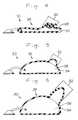
- FIG. 1is a partial cross-sectional side view of one embodiment of the present invention shown as a substantially deflated tissue expander.
- FIG. 2is a partial cross-sectional side view showing the tissue expander of FIG. 1 after partial inflation.
- FIG. 3is a partial cross-sectional side view showing the tissue expander of FIG. 2 after further inflation.
- FIG. 4is a partial cross-sectional side view illustrating a second embodiment of the present invention shown as a substantially deflated tissue expander.
- FIG. 5is a partial cross-sectional side view showing the tissue expander of FIG. 4 after partial inflation.
- FIG. 6is a partial cross-sectional side view showing the tissue expander of FIG. 5 after further inflation.
- FIG. 7is a partial cross-sectional side view illustrating a third embodiment of the present invention shown as an inflated tissue expander.
- FIG. 8is a partial cross-sectional side view illustrating a fourth embodiment of the present invention shown as an inflated tissue expander.
- FIG. 1depicts one form of a tissue expander according to the invention shown as tissue expander 10 implanted beneath the skin 100 of the patient.
- Tissue expander 10consists of a fluid-tight envelope 26 and means for inflating the envelope 26.
- the inflation meansis shown in the form of injection button 24 of conventional design which is designed to permit inflation by addition of a biocompatible fluid such as isotonic saline into pocket 29 of envelope 26.
- a hypodermic syringe needleis used to introduce biocompatible fluid into the hollow region 28 of injection button 24.
- the fluidtravels through the lumen of tube 20 from region 28 into pocket 29 of envelope 26 because the ends of tube 20 are sealed to injection button 24 and envelope 26 at attachment points 22 and 18, respectively, with, for example, a medical grade silicone adhesive such that the lumen 16 is in communication with region 28 and pocket 29.
- Envelope 26is formed from a button and an expandable upper section which together define pocket 29 which is inflatable by a single means for inflation. Means for inflation is shown as injection button 24.
- the expandable upper sectionhas portions 12 and 14, both made of elastic material with portion 12 being formed of a material having a lower modulus of elasticity than the material from which portion 14 is formed.
- portion 12is formed of a material having a lower modulus of elasticity than the material from which portion 14 is formed.
- the bottom of envelope 26is formed of the same material as portion 14, this is not required for the invention. The bottom may be made of the same or different material than any other part of the expander.
- FIG. 2illustrates tissue expander 10 after some inflation.
- FIGS. 2-3 and 5-8show the pockets inflated, but no inflation fluid is shown, for purposes of clarity.
- the fluid used to inflate the envelopesis preferably an isotonic saline solution although other biocompatible fluids which will remain under pressure within the envelope, such as a silicone gel, can also be used.
- portion 12has not begun to expand at a faster rate than portion 14, and therefore envelope 26 has a generally smooth hemispherical shape. Resulting from the expansion of the envelope 26, skin 100 also has expanded and taken on the same general shape of envelope 26.
- the appearance of the tissue expanders of this inventionwill vary depending on the design and the materials used, therefore, the generally smooth shape is not necessarily achieved with every tissue expander of the invention, but is shown here as a possible occurrence and for illustrational purposes.
- FIG. 3illustrates expander 10 which has been inflated to a greater degree than that shown in FIG. 2 wherein portion 12 has expanded more than portion 14 and therefore has caused envelope 26 and skin 100 to each assume a complex shape.
- the different moduli of elasticity of the portionscauses one portion to expand to a greater extent than the other portion some time during the expansion process. It is not necessary that the portion having the lower modulus expand to a greater extent throughout the entire inflation process, but at least during some period of the process.
- the envelopedoes not need to have varying wall thickness to achieve differential expansion.
- portion 12stretches at a faster rate than portion 14. It is not necessary that portion 12 stretch at a faster rate than portion 14 throughout the entire inflation process, but when portion 12 stretches at a faster rate during at least part of the inflation process the envelope is expanded more at portion 12 than at portion 14 to achieve the differential expansion. Also, it is not necessary that one portion expands at a "faster rate" than another; two portions can expand at the same rate and achieve differential expansion.
- an envelope formed of one material which when filled, but not yet expanded or stretchedhas a first end which measure 1 ⁇ high and a second end which measures 2 ⁇ high. It is feasible that this envelope when stretched will take on a generally spherical shape so that each end has generally the same height.
- the moduli of elasticity of the materialscontrols the amount of expansion even though the two ends have expanded at the same rate over period of time: a 50% increase in height for each end.
- FIGS. 4-6illustrate another type of tissue expander according to the invention.
- FIG. 4shows tissue expander 30 having envelope 36.
- Envelope 36is formed of a bottom and an upper section, and the upper section is formed of portions 32 and 34, wherein portion 32 is formed of a material having a lower modulus of elasticity than the material which forms portion 34.
- envelope 36is pre-formed so that portion 32 has excess material and has folds when the envelope is in its deflated state.
- FIG. 5shows expander 30 after inflation of envelope 36.
- portion 32has already caused envelope 36 to take on a complex shape because the excess material has been filled with fluid.
- envelope 36has been inflated beyond that shown in FIG. 5, showing that portion 32 has expanded relatively more than portion 34 and has caused envelope 36 to take on a different shape than that shown in FIG. 5.
- FIG. 7illustrates another embodiment of the invention shown as tissue expander 40 having envelope 49.
- Envelope 49is shown in the inflated state.
- portion 42has a lower modulus of elasticity than portion 44.
- Portion 42is adhered onto portion 44 at an opening 46 in portion 44 which provides fluid communication between the spaces covered by portions 42 and 44.
- Portion 42may be adhered by bonding to portion 44 or it may be adhered by using an adhesive between portions 42 and 44 at area of contact 48.
- a medical grade silicone adhesivecan be used to adhere the two portions if silicone elastomers are used for the envelope.
- portion 42could be laminated to the inside surface of portion 44, so long as it is placed below an opening in portion 44.
- FIG. 8illustrates a preferred embodiment of the invention shown as tissue expander 50 with envelope 59.
- Envelope 59shown in the inflated state, has an inside elastic layer 56 which extends around the entire envelope, an intermediate elastic layer 54 which extends only partially around the envelope, and an outside layer 58 which extends around the entire envelope.
- Inside layer 56 and outside layer 58are formed of the same material, whereas intermediate layer 54 is formed of a material having a higher modulus of elasticity than the other two layers.
- the area of envelope 59 which is deficient of the material which forms layer 54expands further than the remainder of envelope 59, because the composite of the remainder of the envelope includes a material which has a higher modulus of elasticity than the area of envelope 59 which is deficient of layer 54.
- Envelope 59is prepared by first coating a mandrel with a layer of a first polymeric composition, then coating almost all of the coated mandrel with a second polymeric composition which has a higher modulus of elasticity than the first composition leaving a space on the coated mandrel uncoated with the second composition, and then coating the mandrel with the first composition again so that the space left uncoated with the second composition is covered with the first composition.
- the composite compositionsare then cured and removed from the mandrel. It is preferred that silicone elastomer compositions are used for the first and second compositions and, if they are used, generally the compositions will bond together upon curing. However, the two compositions do no necessarily have to capable of bonding together.
- one this techniqueare possible. For example, one could eliminate the inside layer 56 or the outside layer 58 altogether and achieve similar results. One could also use three or more polymeric compositions each with different moduli of elasticity, so long as at least one area of the envelope has a lower modulus of elasticity than the envelope wall surrounding that area, so that a complex shape may be achieved.
- devices of the inventionmay include more than two portions, where the materials forming the portions could each have a different modulus of elasticity.
- the inventionis also suitable for making inflatable mammary prostheses which are implanted, used to differentially expand tissue, then left in the body as prostheses.
- a mammary prosthesiscould be similar to any of the expanders shown in the FIGS 1-8.
- Another proposed designwould be to have a double lumen mammary prosthesis having a chamber inside another chamber, where one chamber is optionally pre-filled with a gel.
- the unfilled chamberwould be composed of at least two materials having different moduli of elasticity to provide for the differential expansion.
- the unfilled chamberis the interior chamber and the gel-filled chamber is the exterior chamber. Having the gel-filled chamber on the outside would help protect the interior chamber and, in case of a rupture, help minimize leaking of the fluid used to fill the interior chamber.
- a tissue expander or a mammary prostheses using this inventionmay also have side-by-side or stacked chambers where one is pre-filled or neither is pre-filled.
- the tissue expander of the inventionmay have a remote injection button as shown in the figures or may have an injection button mounted directly on the envelope.
- an injection buttonwhich can be used with this invention is found in U.S. Patent No. 4,190,040 to Schulte.
- Another injection button which can be used on the envelopeis of the type described in U.S. Patent No. 4,428,364 to Bartolo.
- percutaneous means for inflating the tissue expanderone could use the teaching of Austad in U.S. Patent No. 4,157,085 which teaches osmotically expandable tissue expanders.
- the bottom of the envelopesmay be substantially non-extensible, e.g., using the teaching of Radovan in U.S. Patent No. 4,217,889.
- envelopes according to this inventionmay be formed where the larger portion is formed of the material with the lower modulus of elasticity.
- the envelopes of this inventioncan also be formed with varying wall thicknesses or embedded materials for limiting expansion so that the expansion of the envelope is controlled by both the moduli of elasticity of the materials of construction and another means.
- Envelopes of this inventionhave the potential of being relatively thinner than envelopes solely using varying wall thicknesses to control expansion and still achieve the desired amount of differential expansion. Therefore envelopes of this invention can use less material and reduce the cost of making, can be faster and easier to make because thinner walls require less application of the polymeric composition to a mandrel, if a mandrel is used, and can cure faster than the thicker envelopes.
- when less material and/or fewer applications of the material are required to make the envelopesthere is less chance for dirt pick-up and bubble formation between applied layers and therefore improved overall quality of the envelope results.
- the envelopescan be formed in various ways, e.g. by applying a suitable solution to a mandrel as discussed or, in the case of silicone envelopes, by adhering two sheets of vulcanized elastomer together by imposing an unvulcanized washer between the sheets at the perimeter and curing the washer to the elastomer sheets while applying pressure to the perimeter.
- portion 12is formed of a material having a lower modulus of elasticity than the material used to form portion 14.
- Modulus of elasticitycan be defined as the applied force per unit of original cross sectional area of a test bar of the material at a specific percentage elongation (or tensile stress at a given elongation).
- a silicone elastomer for portion 12 having a tensile stress of about 1378 KPa (200 psi) at 100% elongationworks well with a silicone elastomer for portion 14 having a tensile stress of about 3445 - 4823 KPa (500-700 psi) at 100% elongation.
- the tensile stresseswere measured by a procedure based on ASTM D 412. In this case, the modulus of elasticity of the more elastic material is, as preferred, less than half of the modulus of elasticity of the less elastic material. Using materials wherein one has a modulus of elasticity of less than about 75% than the other would also be highly suitable.
- a preferred way of making materials having a difference in moduli of elasticityis by changing the level of filler in the polymeric compositions. By adding more filler to a composition, the modulus of elasticity is increased, resulting in a stiffer material.
- the effect of fillers on polymer characteristicsis discussed along with the fact that the addition of carbon black in a cross-linked natural rubber shows an increase in stiffness with increase in filler loading.
- Another way of forming materials with varying moduli of elasticityis by varying the crosslink density (or level of cure) or molecular weight with or without changes in filler level, wherein generally, compositions with higher crosslink density have higher moduli.
- the phenomenon of altering the modulus of elasticity with changes in crosslink density or level of cureis discussed on pages 77-89 of the book, Vulcanization of Elastomers (1964), edited by G. Alliger and I. J. Sjothun.
- Another way of acquiring two materials with different moduliis by using materials which have a different polymer base, e.g. where one portion is formed from silicon-polyurethane copolymers and the other is silicone.
- Another wayis by the addition of plasticizers one can create a material with a lower modulus of elasticity. This phenomena is discussed on pages 45-46 of Principles of Polymer Systems .
- the envelopes of the inventioncan be formed by coating a mandrel (by spraying, brushing, dipping, rolling, etc.) with an uncured polymeric composition and, subsequently, curing the composition, or they may be formed by adhering two sheets of elastic material together.
- a mandrelby spraying, brushing, dipping, rolling, etc.
- the envelopehas the further advantage of not having any sharp, rigid or elevated edges which may cut into the patient's tissue and cause discomfort and/or other complications.
- the portions of the upper section responsible for the differential expansionmay be adhered to the envelope by bonding or adhering two bodies of material together with a suitable adhesive.
- tissue 100would rest directly upon expander 10 and button 24 when expander 10 is implanted.
- FIG. 1a partial cross-sectional side view of substantially deflated tissue expander 10 is shown implanted beneath tissue 100 to be expanded according to surgical procedures familiar to those skilled in the art of implantation of tissue expanders. Tissue expander 10 is placed in a surgically-formed opening beneath tissue 100. If means for attaching tissue expander 10 are present it would be used to attach the device to underlying body members and thus help hold envelope 26 in a preselected orientation with respect to the tissue to be expanded.
- fixation tabswhich can be strips of polyester fiber mesh reinforced silicone elastomer fixed to the lower portion of the envelope such as by means of a medical grade silicone adhesive. These tabs would then be sutured to underlying body members, e.g. muscle or fascia.
- a needle of a hypodermic syringe which contains a biocompatible fluidis then passed through tissue 100 and injection button 24 and then fluid is gradually forced into hollow region 28 and, in turn, travels through tube 20 and into interior region 29 of envelope 26. Such injections are done periodically over an extended period of time.
- Envelope 26is inflated with the biocompatible fluid in a well known manner at such a rate that the tissue 100 is expanded over a reasonably short period of time, but not so short a time that tissue necrosis occurs.
- FIG. 2shows tissue expander 10 after some inflation and
- FIG. 3shows tissue expander 10 after inflation beyond that shown in FIG. 2 and enough inflation to see differential expansion, resulting in the tissue taking on a complex shape.
- tissue expander 10may be surgically removed and a prosthesis may be surgically implanted in its place or the expander may be left in as a prosthesis.
Landscapes
- Health & Medical Sciences (AREA)
- Life Sciences & Earth Sciences (AREA)
- Veterinary Medicine (AREA)
- Oral & Maxillofacial Surgery (AREA)
- Public Health (AREA)
- Surgery (AREA)
- General Health & Medical Sciences (AREA)
- Engineering & Computer Science (AREA)
- Biomedical Technology (AREA)
- Heart & Thoracic Surgery (AREA)
- Animal Behavior & Ethology (AREA)
- Molecular Biology (AREA)
- Medical Informatics (AREA)
- Nuclear Medicine, Radiotherapy & Molecular Imaging (AREA)
- Pathology (AREA)
- Dermatology (AREA)
- Cardiology (AREA)
- Transplantation (AREA)
- Vascular Medicine (AREA)
- Prostheses (AREA)
- Materials For Medical Uses (AREA)
Description
- The present invention relates to tissue expanders, including tissue-expanding mammary prostheses, and to methods of making and using such tissue expanders. More particularly, the invention relates to tissue expanders capable of expanding overlying tissue into a complex shape.
- Subcutaneous tissue expanders have come into wide use because of the variety of plastic surgical procedures that have been developed which either require that tissue be expanded to receive or retain an implant or that a flap of tissue be generated for use on some other part of the body.
- EP-A-0 181 720 discloses a tissue expander in which an expandable cover has a thicker limited expansion portion and a thinner differentiel expansion portion both portions made of the same material.
- In view of the tissue expander devices in the prior art, there remains a need for a tissue expander which can shape overlying tissue into a complex shape and 1) can be made with existing manufacturing equipment, 2) whose characteristics can be easily altered to suit many applications, 3) is formed of biocompatible materials, 4) is relatively easy and quick to make and uses a minimum of parts, 5) can have a minimum number of injection sites therefore having a minimum number of injection button connections and minimizing the number of times a patient needs to be injected, 6) can have a uniform wall thickness, 7) is relatively economical, 8) has relatively low rejection rates during production, and 9) provides the surgeon with good control of differential expansion.
- These and other objects can be provided by the implantable tissue expander of the invention which comprises a) a fluid-tight envelope which is inflatable by a single means for inflation and which has an expandable upper section comprising a first elastic portion and a second elastic portion formed of a material having a lower modulus of elasticity than the material forming the first portion, so that during the inflation of the envelope the modulus of elasticity of each portion at least partially controls the amount of expansion of each portion and causes the envelope to assume a complex shape, and b) means for inflating the envelope with a biocompatible fluid associated therewith for the controlled inflation of the envelope. The tissue expanders of the invention are also suitable for inflatable-type mammary prostheses. The invention also provides a method of making an envelope for such a tissue expander and a method of using such a tissue expander.
- The above and other objects and advantages of the present invention will become apparent to those skilled in the art upon an examination of the following description and drawings which are illustrative of the present invention.
- In the drawings:
- FIG. 1 is a partial cross-sectional side view of one embodiment of the present invention shown as a substantially deflated tissue expander.
- FIG. 2 is a partial cross-sectional side view showing the tissue expander of FIG. 1 after partial inflation.
- FIG. 3 is a partial cross-sectional side view showing the tissue expander of FIG. 2 after further inflation.
- FIG. 4 is a partial cross-sectional side view illustrating a second embodiment of the present invention shown as a substantially deflated tissue expander.
- FIG. 5 is a partial cross-sectional side view showing the tissue expander of FIG. 4 after partial inflation.
- FIG. 6 is a partial cross-sectional side view showing the tissue expander of FIG. 5 after further inflation.
- FIG. 7 is a partial cross-sectional side view illustrating a third embodiment of the present invention shown as an inflated tissue expander.
- FIG. 8 is a partial cross-sectional side view illustrating a fourth embodiment of the present invention shown as an inflated tissue expander.
- Referring to the drawings, wherein like reference characters designate corresponding parts throughout the Figures thereof, FIG. 1 depicts one form of a tissue expander according to the invention shown as tissue expander 10 implanted beneath the
skin 100 of the patient. Tissue expander 10 consists of a fluid-tight envelope 26 and means for inflating theenvelope 26. The inflation means is shown in the form ofinjection button 24 of conventional design which is designed to permit inflation by addition of a biocompatible fluid such as isotonic saline intopocket 29 ofenvelope 26. As with such conventional injection buttons, a hypodermic syringe needle is used to introduce biocompatible fluid into thehollow region 28 ofinjection button 24. The fluid travels through the lumen oftube 20 fromregion 28 intopocket 29 ofenvelope 26 because the ends oftube 20 are sealed toinjection button 24 andenvelope 26 atattachment points lumen 16 is in communication withregion 28 andpocket 29. Envelope 26 is formed from a button and an expandable upper section which together definepocket 29 which is inflatable by a single means for inflation. Means for inflation is shown asinjection button 24. The expandable upper section hasportions portion 12 being formed of a material having a lower modulus of elasticity than the material from whichportion 14 is formed. Although it is illustrated that the bottom ofenvelope 26 is formed of the same material asportion 14, this is not required for the invention. The bottom may be made of the same or different material than any other part of the expander.- FIG. 2 illustrates tissue expander 10 after some inflation. FIGS. 2-3 and 5-8 show the pockets inflated, but no inflation fluid is shown, for purposes of clarity. The fluid used to inflate the envelopes is preferably an isotonic saline solution although other biocompatible fluids which will remain under pressure within the envelope, such as a silicone gel, can also be used. In FIG. 2,
portion 12 has not begun to expand at a faster rate thanportion 14, and thereforeenvelope 26 has a generally smooth hemispherical shape. Resulting from the expansion of theenvelope 26,skin 100 also has expanded and taken on the same general shape ofenvelope 26. The appearance of the tissue expanders of this invention will vary depending on the design and the materials used, therefore, the generally smooth shape is not necessarily achieved with every tissue expander of the invention, but is shown here as a possible occurrence and for illustrational purposes. - FIG. 3 illustrates
expander 10 which has been inflated to a greater degree than that shown in FIG. 2 whereinportion 12 has expanded more thanportion 14 and therefore has causedenvelope 26 andskin 100 to each assume a complex shape. This illustrates that the modulus of elasticity of each portion controls the amount of expansion of each portion. Stated another way, the different moduli of elasticity of the portions causes one portion to expand to a greater extent than the other portion some time during the expansion process. It is not necessary that the portion having the lower modulus expand to a greater extent throughout the entire inflation process, but at least during some period of the process. As can be seen with FIGS. 1-8, the envelope does not need to have varying wall thickness to achieve differential expansion. - In this example,
portion 12 stretches at a faster rate thanportion 14. It is not necessary thatportion 12 stretch at a faster rate thanportion 14 throughout the entire inflation process, but whenportion 12 stretches at a faster rate during at least part of the inflation process the envelope is expanded more atportion 12 than atportion 14 to achieve the differential expansion. Also, it is not necessary that one portion expands at a "faster rate" than another; two portions can expand at the same rate and achieve differential expansion. For example, an envelope formed of one material which when filled, but not yet expanded or stretched, has a first end which measure 1˝ high and a second end which measures 2˝ high. It is feasible that this envelope when stretched will take on a generally spherical shape so that each end has generally the same height. In contrast, when using the invention and making a similar envelope but where the first end is made from a material having a higher modulus of elasticity than the second end, expansion could result so that after some inflation the 1˝ high end expands to a height of 1 1/2˝ and the 2˝ end expands to a height of 3˝. In this example, the moduli of elasticity of the materials controls the amount of expansion even though the two ends have expanded at the same rate over period of time: a 50% increase in height for each end. - FIGS. 4-6 illustrate another type of tissue expander according to the invention. FIG. 4 shows tissue expander 30 having
envelope 36.Envelope 36 is formed of a bottom and an upper section, and the upper section is formed ofportions portion 32 is formed of a material having a lower modulus of elasticity than the material which formsportion 34. In this embodiment,envelope 36 is pre-formed so thatportion 32 has excess material and has folds when the envelope is in its deflated state. - FIG. 5 shows expander 30 after inflation of
envelope 36. As can be seen in this illustration,portion 32 has already causedenvelope 36 to take on a complex shape because the excess material has been filled with fluid. In FIG. 6,envelope 36 has been inflated beyond that shown in FIG. 5, showing thatportion 32 has expanded relatively more thanportion 34 and has causedenvelope 36 to take on a different shape than that shown in FIG. 5. - FIG. 7 illustrates another embodiment of the invention shown as tissue expander 40 having
envelope 49.Envelope 49 is shown in the inflated state. In this embodiment,portion 42 has a lower modulus of elasticity thanportion 44.Portion 42 is adhered ontoportion 44 at anopening 46 inportion 44 which provides fluid communication between the spaces covered byportions Portion 42 may be adhered by bonding toportion 44 or it may be adhered by using an adhesive betweenportions contact 48. As an example, a medical grade silicone adhesive can be used to adhere the two portions if silicone elastomers are used for the envelope. Alternatively,portion 42 could be laminated to the inside surface ofportion 44, so long as it is placed below an opening inportion 44. - FIG. 8 illustrates a preferred embodiment of the invention shown as tissue expander 50 with
envelope 59.Envelope 59, shown in the inflated state, has an insideelastic layer 56 which extends around the entire envelope, an intermediateelastic layer 54 which extends only partially around the envelope, and anoutside layer 58 which extends around the entire envelope. Insidelayer 56 andoutside layer 58 are formed of the same material, whereasintermediate layer 54 is formed of a material having a higher modulus of elasticity than the other two layers. The area ofenvelope 59 which is deficient of the material which formslayer 54 expands further than the remainder ofenvelope 59, because the composite of the remainder of the envelope includes a material which has a higher modulus of elasticity than the area ofenvelope 59 which is deficient oflayer 54. Envelope 59 is prepared by first coating a mandrel with a layer of a first polymeric composition, then coating almost all of the coated mandrel with a second polymeric composition which has a higher modulus of elasticity than the first composition leaving a space on the coated mandrel uncoated with the second composition, and then coating the mandrel with the first composition again so that the space left uncoated with the second composition is covered with the first composition. The composite compositions are then cured and removed from the mandrel. It is preferred that silicone elastomer compositions are used for the first and second compositions and, if they are used, generally the compositions will bond together upon curing. However, the two compositions do no necessarily have to capable of bonding together.- Variations one this technique are possible. For example, one could eliminate the
inside layer 56 or theoutside layer 58 altogether and achieve similar results. One could also use three or more polymeric compositions each with different moduli of elasticity, so long as at least one area of the envelope has a lower modulus of elasticity than the envelope wall surrounding that area, so that a complex shape may be achieved. - Although the figures illustrate the combination of only two portions to form the expandable upper section, one being formed of a material having a lower modulus of elasticity than the other, devices of the invention may include more than two portions, where the materials forming the portions could each have a different modulus of elasticity.
- The invention is also suitable for making inflatable mammary prostheses which are implanted, used to differentially expand tissue, then left in the body as prostheses. For example, such a mammary prosthesis could be similar to any of the expanders shown in the FIGS 1-8. Another proposed design would be to have a double lumen mammary prosthesis having a chamber inside another chamber, where one chamber is optionally pre-filled with a gel. The unfilled chamber would be composed of at least two materials having different moduli of elasticity to provide for the differential expansion. Preferably, the unfilled chamber is the interior chamber and the gel-filled chamber is the exterior chamber. Having the gel-filled chamber on the outside would help protect the interior chamber and, in case of a rupture, help minimize leaking of the fluid used to fill the interior chamber. A tissue expander or a mammary prostheses using this invention may also have side-by-side or stacked chambers where one is pre-filled or neither is pre-filled.
- The tissue expander of the invention may have a remote injection button as shown in the figures or may have an injection button mounted directly on the envelope. One example of an injection button which can be used with this invention is found in U.S. Patent No. 4,190,040 to Schulte. Another injection button which can be used on the envelope is of the type described in U.S. Patent No. 4,428,364 to Bartolo. As an alternative to using percutaneous means for inflating the tissue expander, one could use the teaching of Austad in U.S. Patent No. 4,157,085 which teaches osmotically expandable tissue expanders. The bottom of the envelopes may be substantially non-extensible, e.g., using the teaching of Radovan in U.S. Patent No. 4,217,889.
- Although it is illustrated in the figures that the portion formed of the material with the lower modulus of elasticity is smaller than the other portion, envelopes according to this invention may be formed where the larger portion is formed of the material with the lower modulus of elasticity.
- The envelopes of this invention can also be formed with varying wall thicknesses or embedded materials for limiting expansion so that the expansion of the envelope is controlled by both the moduli of elasticity of the materials of construction and another means. There are several advantages of making the envelopes according to this invention whether or not in combination with other ways of controlling expansion. Envelopes of this invention have the potential of being relatively thinner than envelopes solely using varying wall thicknesses to control expansion and still achieve the desired amount of differential expansion. Therefore envelopes of this invention can use less material and reduce the cost of making, can be faster and easier to make because thinner walls require less application of the polymeric composition to a mandrel, if a mandrel is used, and can cure faster than the thicker envelopes. In addition, when less material and/or fewer applications of the material are required to make the envelopes there is less chance for dirt pick-up and bubble formation between applied layers and therefore improved overall quality of the envelope results.
- The envelopes of this invention are preferably constructed of biocompatible silicone elastomers similar to the medical grade silicone elastomers commonly used in the manufacture of mammary implants or tissue expanders (e.g., those which are available from Dow Corning Corporation, Midland, MI 48686), but could be manufactured of other biocompatible elastic materials, such as polyurethanes. It is preferred that silicone elastomers which cure via ≡SiH to CH₂=CHSi≡ addition, in the presence of a catalyst, such as a platinum catalyst, are used. When using silicone elastomers as the materials for forming
portions - As discussed previously,
portion 12 is formed of a material having a lower modulus of elasticity than the material used to formportion 14. Modulus of elasticity can be defined as the applied force per unit of original cross sectional area of a test bar of the material at a specific percentage elongation (or tensile stress at a given elongation). Although any difference in tensile stress at a given elongation would suffice for the invention, it has been found that a silicone elastomer forportion 12 having a tensile stress of about 1378 KPa (200 psi) at 100% elongation works well with a silicone elastomer forportion 14 having a tensile stress of about 3445 - 4823 KPa (500-700 psi) at 100% elongation. The tensile stresses were measured by a procedure based on ASTM D 412. In this case, the modulus of elasticity of the more elastic material is, as preferred, less than half of the modulus of elasticity of the less elastic material. Using materials wherein one has a modulus of elasticity of less than about 75% than the other would also be highly suitable. - As mentioned, a preferred way of making materials having a difference in moduli of elasticity is by changing the level of filler in the polymeric compositions. By adding more filler to a composition, the modulus of elasticity is increased, resulting in a stiffer material. For example, on page 216 of the book,Principles of Polymer Systems (1970), by Ferdinand Rodriguez, the effect of fillers on polymer characteristics is discussed along with the fact that the addition of carbon black in a cross-linked natural rubber shows an increase in stiffness with increase in filler loading.
- Another way of forming materials with varying moduli of elasticity is by varying the crosslink density (or level of cure) or molecular weight with or without changes in filler level, wherein generally, compositions with higher crosslink density have higher moduli. The phenomenon of altering the modulus of elasticity with changes in crosslink density or level of cure is discussed on pages 77-89 of the book,Vulcanization of Elastomers (1964), edited by G. Alliger and I. J. Sjothun. Another way of acquiring two materials with different moduli is by using materials which have a different polymer base, e.g. where one portion is formed from silicon-polyurethane copolymers and the other is silicone. Another way is by the addition of plasticizers one can create a material with a lower modulus of elasticity. This phenomena is discussed on pages 45-46 ofPrinciples of Polymer Systems.
- To make the envelopes of the invention any known fabrication technique may be used. For example, the envelopes can be formed by coating a mandrel (by spraying, brushing, dipping, rolling, etc.) with an uncured polymeric composition and, subsequently, curing the composition, or they may be formed by adhering two sheets of elastic material together. When the envelope is formed by using a mandrel with rounded edges, the envelope has the further advantage of not having any sharp, rigid or elevated edges which may cut into the patient's tissue and cause discomfort and/or other complications. The portions of the upper section responsible for the differential expansion, may be adhered to the envelope by bonding or adhering two bodies of material together with a suitable adhesive.
- Having described several embodiments of the tissue expander, the manner in which it can be used will now be described with reference to FIGS. 1-3. It is to be understood that
tissue 100 would rest directly uponexpander 10 andbutton 24 whenexpander 10 is implanted. In FIG. 1, a partial cross-sectional side view of substantially deflatedtissue expander 10 is shown implanted beneathtissue 100 to be expanded according to surgical procedures familiar to those skilled in the art of implantation of tissue expanders.Tissue expander 10 is placed in a surgically-formed opening beneathtissue 100. If means for attachingtissue expander 10 are present it would be used to attach the device to underlying body members and thus help holdenvelope 26 in a preselected orientation with respect to the tissue to be expanded. Such means could be, for example, fixation tabs which can be strips of polyester fiber mesh reinforced silicone elastomer fixed to the lower portion of the envelope such as by means of a medical grade silicone adhesive. These tabs would then be sutured to underlying body members, e.g. muscle or fascia. A needle of a hypodermic syringe which contains a biocompatible fluid is then passed throughtissue 100 andinjection button 24 and then fluid is gradually forced intohollow region 28 and, in turn, travels throughtube 20 and intointerior region 29 ofenvelope 26. Such injections are done periodically over an extended period of time.Envelope 26 is inflated with the biocompatible fluid in a well known manner at such a rate that thetissue 100 is expanded over a reasonably short period of time, but not so short a time that tissue necrosis occurs. FIG. 2 showstissue expander 10 after some inflation and FIG. 3 showstissue expander 10 after inflation beyond that shown in FIG. 2 and enough inflation to see differential expansion, resulting in the tissue taking on a complex shape. - After the envelope has been inflated to the desired degree,
tissue expander 10 may be surgically removed and a prosthesis may be surgically implanted in its place or the expander may be left in as a prosthesis. - These and other variations of the present invention may be made which fall within the scope of the appended claims even though such variations were not specifically discussed above.
Claims (20)
Applications Claiming Priority (2)
| Application Number | Priority Date | Filing Date | Title |
|---|---|---|---|
| US134331 | 1987-12-17 | ||
| US07/134,331US4841992A (en) | 1987-12-17 | 1987-12-17 | Tissue expander and method of making and using |
Publications (2)
| Publication Number | Publication Date |
|---|---|
| EP0324234A1 EP0324234A1 (en) | 1989-07-19 |
| EP0324234B1true EP0324234B1 (en) | 1992-06-10 |
Family
ID=22462869
Family Applications (1)
| Application Number | Title | Priority Date | Filing Date |
|---|---|---|---|
| EP88310894AExpired - LifetimeEP0324234B1 (en) | 1987-12-17 | 1988-11-18 | Tissue expander and method of making and using |
Country Status (5)
| Country | Link |
|---|---|
| US (1) | US4841992A (en) |
| EP (1) | EP0324234B1 (en) |
| JP (1) | JPH027953A (en) |
| CA (1) | CA1328543C (en) |
| DE (1) | DE3871933T2 (en) |
Cited By (4)
| Publication number | Priority date | Publication date | Assignee | Title |
|---|---|---|---|---|
| FR2646088A1 (en)* | 1989-04-19 | 1990-10-26 | Ruiz Razura Amado | INFLATABLE ENVELOPE FOR ELONGATION OF BIOLOGICAL TISSUES |
| EP0412703A1 (en)* | 1989-08-07 | 1991-02-13 | Bristol-Myers Squibb Company | Self-sealing tissue expander and method |
| US5571138A (en)* | 1991-03-06 | 1996-11-05 | Stretchex Ab | Surgical stretching device for the expansion of tissue |
| US9387068B2 (en) | 2008-08-20 | 2016-07-12 | Allergan, Inc. | Self-sealing shell for inflatable prostheses |
Families Citing this family (57)
| Publication number | Priority date | Publication date | Assignee | Title |
|---|---|---|---|---|
| US5146933A (en)* | 1991-09-20 | 1992-09-15 | Dow Corning Wright Corporation | Implantable prosthetic device and tethered inflation valve for volume |
| US5578085A (en)* | 1991-11-27 | 1996-11-26 | Board Of Regents The University Of Texas System | Balloon prosthesis for the lung and methods of making and using same |
| WO1993021850A1 (en)* | 1992-05-04 | 1993-11-11 | Rosenberg Paul H | Tissue expander apparatus |
| DE4328158C2 (en)* | 1993-08-21 | 2003-11-06 | Johann Rull | Prosthesis to prevent urinary incontinence in women |
| DE69521793T2 (en)* | 1994-03-31 | 2002-08-08 | Ernest C. Manders | DIMENSIONALLY ADAPTABLE TISSUE EXTENSION DEVICE |
| US6071309A (en)* | 1995-03-22 | 2000-06-06 | Knowlton; Edward W. | Segmental breast expander for use in breast reconstruction |
| US5935164A (en)* | 1997-02-25 | 1999-08-10 | Pmt Corporaton | Laminated prosthesis and method of manufacture |
| US6156065A (en)* | 1997-09-10 | 2000-12-05 | Board Of Trustees Of The University Of Arkansas | Natural fixation of breast prosthesis |
| US6315796B1 (en) | 1999-05-13 | 2001-11-13 | Board Of Trustees Of The University Of Arkansas | Flexible seamless memory tissue expanding implant |
| US6520989B1 (en) | 2000-01-18 | 2003-02-18 | Board Of Trustees Of The University Of Arkansas | Extreme volume flexible integrity prosthesis |
| US20040185421A1 (en)* | 2003-03-18 | 2004-09-23 | Cagenix, Inc. | Method of using a tissue contourer |
| AU2003902604A0 (en)* | 2003-05-26 | 2003-06-12 | Connell, Anthony Francis | A differential tissue expander implant |
| US6875233B1 (en) | 2003-06-10 | 2005-04-05 | Hinging breast implant | |
| JP5009158B2 (en)* | 2004-09-21 | 2012-08-22 | シャロン ヴェンチャーズ インコーポレイテッド | Tissue expansion device |
| US20060217757A1 (en)* | 2005-03-28 | 2006-09-28 | Horndeski Gary M | Device and method of weight control via indirect abdominal cavity volume reduction |
| US20080221704A1 (en)* | 2007-03-05 | 2008-09-11 | Ricardo Alfredo Fuenmayor Aray | Three (3) distinct improvements (different fields of use) to the prior art or invention entitled instant face-lifter |
| US8282684B2 (en)* | 2007-03-05 | 2012-10-09 | Ricardo Alfredo Fuenmayor Aray | Instant face-lifter |
| US8313527B2 (en)* | 2007-11-05 | 2012-11-20 | Allergan, Inc. | Soft prosthesis shell texturing method |
| US9050184B2 (en) | 2008-08-13 | 2015-06-09 | Allergan, Inc. | Dual plane breast implant |
| JP5666448B2 (en)* | 2008-08-13 | 2015-02-12 | アラーガン、インコーポレイテッドAllergan,Incorporated | Soft-filled prosthetic shell with a separate fixation surface |
| US8506627B2 (en)* | 2008-08-13 | 2013-08-13 | Allergan, Inc. | Soft filled prosthesis shell with discrete fixation surfaces |
| SI3187219T1 (en) | 2008-12-02 | 2020-09-30 | Allergan, Inc. | Injection device |
| CA2941286C (en)* | 2009-05-13 | 2018-10-16 | Allergan, Inc. | Implants and methods for manufacturing same |
| US20110093069A1 (en) | 2009-10-16 | 2011-04-21 | Allergan, Inc. | Implants and methdos for manufacturing same |
| AU2010330722B2 (en) | 2009-12-18 | 2015-08-20 | Airxpanders, Inc. | Tissue expanders and methods of use |
| WO2011094155A2 (en)* | 2010-01-28 | 2011-08-04 | Allergan, Inc. | Open celled foams, implants including them and processes for making same |
| US20110196488A1 (en)* | 2010-02-03 | 2011-08-11 | Allergan, Inc. | Degradation resistant implantable materials and methods |
| US9072821B2 (en) | 2010-02-05 | 2015-07-07 | Allergan, Inc. | Biocompatible structures and compositions |
| US8889751B2 (en) | 2010-09-28 | 2014-11-18 | Allergan, Inc. | Porous materials, methods of making and uses |
| US9138308B2 (en) | 2010-02-03 | 2015-09-22 | Apollo Endosurgery, Inc. | Mucosal tissue adhesion via textured surface |
| US8877822B2 (en) | 2010-09-28 | 2014-11-04 | Allergan, Inc. | Porogen compositions, methods of making and uses |
| US9044897B2 (en) | 2010-09-28 | 2015-06-02 | Allergan, Inc. | Porous materials, methods of making and uses |
| US9205577B2 (en) | 2010-02-05 | 2015-12-08 | Allergan, Inc. | Porogen compositions, methods of making and uses |
| US9138309B2 (en) | 2010-02-05 | 2015-09-22 | Allergan, Inc. | Porous materials, methods of making and uses |
| US8636797B2 (en)* | 2010-02-05 | 2014-01-28 | Allergan, Inc. | Inflatable prostheses and methods of making same |
| CA2787458C (en) | 2010-02-05 | 2017-05-16 | Allergan, Inc. | Inflatable prostheses and methods of making same |
| CA2797691A1 (en) | 2010-04-27 | 2011-11-03 | Alexei Goraltchouk | Foam-like materials and methods for producing same |
| US11202853B2 (en) | 2010-05-11 | 2021-12-21 | Allergan, Inc. | Porogen compositions, methods of making and uses |
| AU2011252017B2 (en) | 2010-05-11 | 2015-07-16 | Allergan, Inc. | Porogen compositions, methods of making and uses |
| US8679279B2 (en) | 2010-11-16 | 2014-03-25 | Allergan, Inc. | Methods for creating foam-like texture |
| US8546458B2 (en) | 2010-12-07 | 2013-10-01 | Allergan, Inc. | Process for texturing materials |
| US8801782B2 (en) | 2011-12-15 | 2014-08-12 | Allergan, Inc. | Surgical methods for breast reconstruction or augmentation |
| CA2895083A1 (en) | 2012-12-13 | 2014-06-19 | Allergan, Inc. | Device and method for making a variable surface breast implant |
| EP3954286A1 (en) | 2013-02-21 | 2022-02-16 | Airxpanders, Inc. | Implantable tissue expanders |
| WO2014167381A1 (en)* | 2013-04-09 | 2014-10-16 | Penagos Diego | Preformed tissue expander for ear reconstruction |
| US20140350518A1 (en) | 2013-05-23 | 2014-11-27 | Allergan, Inc. | Syringe extrusion accessory |
| US10029048B2 (en) | 2014-05-13 | 2018-07-24 | Allergan, Inc. | High force injection devices |
| US10092392B2 (en) | 2014-05-16 | 2018-10-09 | Allergan, Inc. | Textured breast implant and methods of making same |
| US9539086B2 (en) | 2014-05-16 | 2017-01-10 | Allergan, Inc. | Soft filled prosthesis shell with variable texture |
| US10226585B2 (en) | 2014-10-01 | 2019-03-12 | Allergan, Inc. | Devices for injection and dosing |
| EP3268063A4 (en) | 2015-03-10 | 2018-10-31 | Allergan Pharmaceuticals Holdings (Ireland) Unlimited Company | Multiple needle injector |
| CN109310827B (en) | 2016-04-08 | 2021-09-07 | 阿勒根公司 | Suction and Injection Devices |
| USD867582S1 (en) | 2017-03-24 | 2019-11-19 | Allergan, Inc. | Syringe device |
| CN107088111B (en)* | 2017-05-31 | 2018-10-02 | 北京五维医疗美容门诊部有限公司 | A kind of chest enhancement prosthesis auxiliary device for posting and prosthese method for posting |
| EP3849458A1 (en) | 2018-09-13 | 2021-07-21 | Allergan, Inc. | Tissue expansion device |
| USD896383S1 (en) | 2018-09-13 | 2020-09-15 | Allergan, Inc. | Tissue expansion device |
| BR112022010124A2 (en)* | 2019-11-25 | 2022-09-06 | Tepha Inc | BREAST IMPLANT WRAPS TO LIMIT BREAST IMPLANT MOVEMENT AND RELATED METHODS |
Family Cites Families (13)
| Publication number | Priority date | Publication date | Assignee | Title |
|---|---|---|---|---|
| US3831583A (en)* | 1971-03-05 | 1974-08-27 | Univ California | Implantable bulb for inflation of surgical implements |
| US4217889A (en)* | 1976-09-15 | 1980-08-19 | Heyer-Schulte Corporation | Flap development device and method of progressively increasing skin area |
| US4222384A (en)* | 1977-11-09 | 1980-09-16 | Biomedical Engineering Associates, Inc. | Catheter |
| US4157085A (en)* | 1978-03-24 | 1979-06-05 | Dow Corning Corporation | Surgically implantable tissue expanding device and the method of its use |
| US4205401A (en)* | 1978-05-25 | 1980-06-03 | Dow Corning Corporation | Mammary prosthesis which resists capsular contracture |
| CA1230951A (en)* | 1983-01-20 | 1988-01-05 | Lance J. Laforest | Mammary prosthesis having adjustable projection |
| US4605412A (en)* | 1983-01-20 | 1986-08-12 | Medical Engineering Corp. | Mammary prosthesis having adjustable projection |
| US4643733A (en)* | 1983-04-04 | 1987-02-17 | Hilton Becker | Permanent reconstruction implant and method of performing human tissue expansion |
| US4574780A (en)* | 1984-11-13 | 1986-03-11 | Manders Ernest K | Tissue expander and method |
| US4615704A (en)* | 1984-11-26 | 1986-10-07 | Dow Corning Corporation | Shape retention tissue expander and method of using |
| US4685447A (en)* | 1985-03-25 | 1987-08-11 | Pmt Corporation | Tissue expander system |
| US4651717A (en)* | 1985-04-04 | 1987-03-24 | Dow Corning Corporation | Multiple envelope tissue expander device |
| US4671255A (en)* | 1985-10-16 | 1987-06-09 | Mcghan Medical Corporation | Tissue expander with self-contained injection reservoir and reinforcing insert |
- 1987
- 1987-12-17USUS07/134,331patent/US4841992A/ennot_activeExpired - Fee Related
- 1988
- 1988-10-25CACA000581171Apatent/CA1328543C/ennot_activeExpired - Fee Related
- 1988-11-18EPEP88310894Apatent/EP0324234B1/ennot_activeExpired - Lifetime
- 1988-11-18DEDE8888310894Tpatent/DE3871933T2/ennot_activeExpired - Fee Related
- 1988-12-16JPJP63316616Apatent/JPH027953A/enactivePending
Cited By (4)
| Publication number | Priority date | Publication date | Assignee | Title |
|---|---|---|---|---|
| FR2646088A1 (en)* | 1989-04-19 | 1990-10-26 | Ruiz Razura Amado | INFLATABLE ENVELOPE FOR ELONGATION OF BIOLOGICAL TISSUES |
| EP0412703A1 (en)* | 1989-08-07 | 1991-02-13 | Bristol-Myers Squibb Company | Self-sealing tissue expander and method |
| US5571138A (en)* | 1991-03-06 | 1996-11-05 | Stretchex Ab | Surgical stretching device for the expansion of tissue |
| US9387068B2 (en) | 2008-08-20 | 2016-07-12 | Allergan, Inc. | Self-sealing shell for inflatable prostheses |
Also Published As
| Publication number | Publication date |
|---|---|
| CA1328543C (en) | 1994-04-19 |
| EP0324234A1 (en) | 1989-07-19 |
| DE3871933D1 (en) | 1992-07-16 |
| US4841992A (en) | 1989-06-27 |
| DE3871933T2 (en) | 1993-07-01 |
| JPH027953A (en) | 1990-01-11 |
Similar Documents
| Publication | Publication Date | Title |
|---|---|---|
| EP0324234B1 (en) | Tissue expander and method of making and using | |
| US4899764A (en) | Tissue expander and method of making and using | |
| US5035249A (en) | Method of making envelope for tissue expander | |
| US5133753A (en) | Method for expanding a self-sealing tissue prosthesis | |
| US5066303A (en) | Self-sealing tissue expander and method | |
| US10765506B2 (en) | Inflatable prostheses and methods of making same | |
| CA1249103A (en) | Multiple envelope tissue expander device | |
| US4205401A (en) | Mammary prosthesis which resists capsular contracture | |
| US8636797B2 (en) | Inflatable prostheses and methods of making same | |
| US5141508A (en) | Tissue expander | |
| US4019499A (en) | Compression implant for urinary incontinence | |
| US6315796B1 (en) | Flexible seamless memory tissue expanding implant | |
| US20130245758A1 (en) | Inflatable prostheses and methods of making same | |
| KR20110037929A (en) | Synthetic Polyisoprene Foley Catheter | |
| US4483331A (en) | Rod-type penile implant | |
| US4775379A (en) | Self-sealing valve for fluid fillable article | |
| CA1151042A (en) | Self-sealing injection button and method of making same | |
| US20250114187A1 (en) | Inflatable prostheses and methods of making same | |
| EP1131126B1 (en) | Double-layered non-porous balloon catheter | |
| JPH03140155A (en) | Complementarily forming material | |
| WO2014042940A1 (en) | Inflatable prostheses and methods of making same |
Legal Events
| Date | Code | Title | Description |
|---|---|---|---|
| PUAI | Public reference made under article 153(3) epc to a published international application that has entered the european phase | Free format text:ORIGINAL CODE: 0009012 | |
| AK | Designated contracting states | Kind code of ref document:A1 Designated state(s):DE FR GB | |
| 17P | Request for examination filed | Effective date:19890905 | |
| 17Q | First examination report despatched | Effective date:19910121 | |
| GRAA | (expected) grant | Free format text:ORIGINAL CODE: 0009210 | |
| AK | Designated contracting states | Kind code of ref document:B1 Designated state(s):DE FR GB | |
| REF | Corresponds to: | Ref document number:3871933 Country of ref document:DE Date of ref document:19920716 | |
| ET | Fr: translation filed | ||
| PLBE | No opposition filed within time limit | Free format text:ORIGINAL CODE: 0009261 | |
| STAA | Information on the status of an ep patent application or granted ep patent | Free format text:STATUS: NO OPPOSITION FILED WITHIN TIME LIMIT | |
| 26N | No opposition filed | ||
| PGFP | Annual fee paid to national office [announced via postgrant information from national office to epo] | Ref country code:FR Payment date:19930901 Year of fee payment:6 | |
| PGFP | Annual fee paid to national office [announced via postgrant information from national office to epo] | Ref country code:DE Payment date:19930906 Year of fee payment:6 | |
| PGFP | Annual fee paid to national office [announced via postgrant information from national office to epo] | Ref country code:GB Payment date:19930913 Year of fee payment:6 | |
| PG25 | Lapsed in a contracting state [announced via postgrant information from national office to epo] | Ref country code:GB Effective date:19941118 | |
| GBPC | Gb: european patent ceased through non-payment of renewal fee | Effective date:19941118 | |
| PG25 | Lapsed in a contracting state [announced via postgrant information from national office to epo] | Ref country code:FR Effective date:19950731 | |
| PG25 | Lapsed in a contracting state [announced via postgrant information from national office to epo] | Ref country code:DE Effective date:19950801 | |
| REG | Reference to a national code | Ref country code:FR Ref legal event code:ST |