EP0323610B1 - Process and device for thickening waste water sludges and/or other organic sludges by means of separating water from solids - Google Patents
Process and device for thickening waste water sludges and/or other organic sludges by means of separating water from solidsDownload PDFInfo
- Publication number
- EP0323610B1 EP0323610B1EP88121473AEP88121473AEP0323610B1EP 0323610 B1EP0323610 B1EP 0323610B1EP 88121473 AEP88121473 AEP 88121473AEP 88121473 AEP88121473 AEP 88121473AEP 0323610 B1EP0323610 B1EP 0323610B1
- Authority
- EP
- European Patent Office
- Prior art keywords
- vessel
- sludge
- flotation
- gas
- pipe
- Prior art date
- Legal status (The legal status is an assumption and is not a legal conclusion. Google has not performed a legal analysis and makes no representation as to the accuracy of the status listed.)
- Expired - Lifetime
Links
Images

Classifications
- C—CHEMISTRY; METALLURGY
- C02—TREATMENT OF WATER, WASTE WATER, SEWAGE, OR SLUDGE
- C02F—TREATMENT OF WATER, WASTE WATER, SEWAGE, OR SLUDGE
- C02F3/00—Biological treatment of water, waste water, or sewage
- C02F3/02—Aerobic processes
- C02F3/12—Activated sludge processes
- C02F3/1205—Particular type of activated sludge processes
- C02F3/1221—Particular type of activated sludge processes comprising treatment of the recirculated sludge
- B—PERFORMING OPERATIONS; TRANSPORTING
- B01—PHYSICAL OR CHEMICAL PROCESSES OR APPARATUS IN GENERAL
- B01D—SEPARATION
- B01D21/00—Separation of suspended solid particles from liquids by sedimentation
- B—PERFORMING OPERATIONS; TRANSPORTING
- B01—PHYSICAL OR CHEMICAL PROCESSES OR APPARATUS IN GENERAL
- B01D—SEPARATION
- B01D21/00—Separation of suspended solid particles from liquids by sedimentation
- B01D21/0039—Settling tanks provided with contact surfaces, e.g. baffles, particles
- B—PERFORMING OPERATIONS; TRANSPORTING
- B01—PHYSICAL OR CHEMICAL PROCESSES OR APPARATUS IN GENERAL
- B01D—SEPARATION
- B01D21/00—Separation of suspended solid particles from liquids by sedimentation
- B01D21/0039—Settling tanks provided with contact surfaces, e.g. baffles, particles
- B01D21/0042—Baffles or guide plates
- B—PERFORMING OPERATIONS; TRANSPORTING
- B01—PHYSICAL OR CHEMICAL PROCESSES OR APPARATUS IN GENERAL
- B01D—SEPARATION
- B01D21/00—Separation of suspended solid particles from liquids by sedimentation
- B01D21/02—Settling tanks with single outlets for the separated liquid
- B—PERFORMING OPERATIONS; TRANSPORTING
- B01—PHYSICAL OR CHEMICAL PROCESSES OR APPARATUS IN GENERAL
- B01D—SEPARATION
- B01D21/00—Separation of suspended solid particles from liquids by sedimentation
- B01D21/24—Feed or discharge mechanisms for settling tanks
- B01D21/2427—The feed or discharge opening located at a distant position from the side walls
- B—PERFORMING OPERATIONS; TRANSPORTING
- B01—PHYSICAL OR CHEMICAL PROCESSES OR APPARATUS IN GENERAL
- B01D—SEPARATION
- B01D21/00—Separation of suspended solid particles from liquids by sedimentation
- B01D21/24—Feed or discharge mechanisms for settling tanks
- B01D21/2433—Discharge mechanisms for floating particles
- B01D21/2438—Discharge mechanisms for floating particles provided with scrapers on the liquid surface for removing floating particles
- B—PERFORMING OPERATIONS; TRANSPORTING
- B01—PHYSICAL OR CHEMICAL PROCESSES OR APPARATUS IN GENERAL
- B01D—SEPARATION
- B01D21/00—Separation of suspended solid particles from liquids by sedimentation
- B01D21/30—Control equipment
- B01D21/307—Passive control mechanisms without external energy, e.g. using a float
- B—PERFORMING OPERATIONS; TRANSPORTING
- B01—PHYSICAL OR CHEMICAL PROCESSES OR APPARATUS IN GENERAL
- B01D—SEPARATION
- B01D21/00—Separation of suspended solid particles from liquids by sedimentation
- B01D21/30—Control equipment
- B01D21/34—Controlling the feed distribution; Controlling the liquid level ; Control of process parameters
- C—CHEMISTRY; METALLURGY
- C02—TREATMENT OF WATER, WASTE WATER, SEWAGE, OR SLUDGE
- C02F—TREATMENT OF WATER, WASTE WATER, SEWAGE, OR SLUDGE
- C02F1/00—Treatment of water, waste water, or sewage
- C02F1/24—Treatment of water, waste water, or sewage by flotation
- C—CHEMISTRY; METALLURGY
- C02—TREATMENT OF WATER, WASTE WATER, SEWAGE, OR SLUDGE
- C02F—TREATMENT OF WATER, WASTE WATER, SEWAGE, OR SLUDGE
- C02F11/00—Treatment of sludge; Devices therefor
- C02F11/12—Treatment of sludge; Devices therefor by de-watering, drying or thickening
- Y—GENERAL TAGGING OF NEW TECHNOLOGICAL DEVELOPMENTS; GENERAL TAGGING OF CROSS-SECTIONAL TECHNOLOGIES SPANNING OVER SEVERAL SECTIONS OF THE IPC; TECHNICAL SUBJECTS COVERED BY FORMER USPC CROSS-REFERENCE ART COLLECTIONS [XRACs] AND DIGESTS
- Y02—TECHNOLOGIES OR APPLICATIONS FOR MITIGATION OR ADAPTATION AGAINST CLIMATE CHANGE
- Y02W—CLIMATE CHANGE MITIGATION TECHNOLOGIES RELATED TO WASTEWATER TREATMENT OR WASTE MANAGEMENT
- Y02W10/00—Technologies for wastewater treatment
- Y02W10/10—Biological treatment of water, waste water, or sewage
Definitions
- the inventionrelates to a process for thickening sewage sludge and / or other organic sludge by separating water and solid particles and to a device for carrying out the process.
- sludgeIn wastewater treatment, sludge is generated in mechanical and chemical cleaning systems and in the clarification of the biological stage. Depending on the type of original contamination of the wastewater and its treatment, these sludges are composed of mineral and / or organic components. They have a water content of between 97 and 99% when they are removed from the cleaning process. In order to reduce this water content, which is an essential requirement for the further processing of the sludge, it is known to further treat the sludge in thickeners. Such thickeners are usually round tanks in which the sludge is stored for several hours to a day and in which the solid particles settle during this time. In such dikes, the water content can be reduced to approx. 92 to 95% depending on the starting sludge.
- waste gas sludgewhich is pressurized with pressure is passed through the discharge device of a pressure vessel and a semi-explosive drop in pressure of each amount of sludge is carried out immediately behind the discharge device.
- the achievable dewatering effectis influenced not only by the particular type of sludge but also by the pressurization and the residence time in the respective reaction vessel.
- the pressureis applied up to max. 7 bar. With special sludges, a higher pressure can also be applied, with a pressure of up to approx. 8 bar being applied in the closed container during sedimentation.
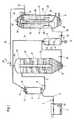
- Fig. 1shows schematically the basic structure of a system having the inventive device, partly in section.
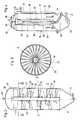
- FIG. 2shows a vertical section through the pressurized container (sedimentation container); 3 shows a horizontal section and a top view of the container according to FIG. 2, specifically along the section line III-III in FIG. 2; 4 shows a vertical section through the pressureless container (flotation container); 5 shows a detail vertical section through a sedimentation container of another type; Fig. 7 is a diagram showing the position of the individual switching elements (valves, level switches) of the system depending on the individual work cycles.
- Fig. 1those parts of the plant are shown, which serve the thickening of the sludge, which is obtained from a wastewater treatment plant, of which, however, only the sludge collecting basin 1 is shown, both excess sludge and primary sludge being able to be produced here.
- a line 2which can be shut off by means of a valve 3 leads into the feed lock 4, in which a level controller 5 is provided, which serves to control the valves in this system.
- Another line 7, which can also be shut off by a valve 6,leads from the bottom area of the feed lock 4 to the pressurizable container 8 (sedimentation container), this line 7 opening into its upper region and passing there into a distribution channel 19 of any design.
- a compressed air line 13 fed by a compressor 12also opens into the bottom area of the bagging container 11.
- a connecting line 14leads from the lid area of this gassing container 11 to the upper area of the loading lock 4, and this connecting line connects these two system parts 4 and 11 in a communicating manner.
- the gassing container 11is connected to the pressureless container 15 (flotation container) via the feed line 29, which can likewise be shut off with a valve 16.
- a level switch 45is also provided in the gassing container 11, which switches the valves controls the system.
- the outlet line 25opens with a built-in shut-off element 26 and throttle 27.
- the pressurizable container 8(sedimentation container) is tower-like, so it is taller than it is wide and it expediently has a circular cross section. Its lower area is formed by a hollow cone 17 standing on the tip, in which the mouth of the discharge line 9 also lies. Adjacent to the ceiling 18 is the line 7 for the sludge entry, which expediently transfers into the distribution channel 19.
- a tubular collecting shaft 20is arranged, the upper end of which is open towards the cover 18. A multiplicity of openings 21 are cut out in the wall of this tubular shaft 20.
- channel-like covers 22are connected, which are essentially horizontal and which are open towards the bottom.
- the aforementioned hood-like covers 22run from the tubular shaft 20 approximately radially to the outer wall of the container 8.
- the cross section of these hood-like covers 22is V-shaped, the two legs of each cover 22 being of unequal height.
- One leg 23has a substantially constant height over the axial length of the cover 22, whereas the height of the other leg 24 increases with increasing distance from the tubular shaft against the wall of the container 8. This can be seen from Figures 2 and 3.
- the openings 21 in the tubular shaft 20are spaced from one another at more or less regular intervals, both along the circumference of the shaft 20 and above its vertical height, these openings 21 preferably being arranged on an imaginary helix (FIG. 2) .
- these covers 22cover the cross-section of the container 8 for the most part in the plan, but it should be considered and observed, that the individual covers are at different heights.
- These covers 22are also arranged so that - in circulation - one leg 24 follows each other in alternation on a leg 23 of constant height. This makes Fig. 3 clear.
- the pressure-free container 15is also tower-like and open at the top.
- the inside openings 28 of the feed line 29are distanced from the bottom area and lie approximately in the lower third of the height of the container 15 and are arranged to run upwards or tangentially.
- a discharge pipe 30is connected below the mouth openings 28, the upper end of which leads into an overflow 31 which can be adjusted to the filling level of the container 15.
- a vertical shaft 33is provided, which at its lower end merges into a discharge line 34 which runs through the wall of the container 15.
- the upper end of the vertical shaft 33is widened outward in a funnel-like manner and directly adjoining this funnel-like extension 35 is a reamer 36, which is rotatably mounted about an axis coaxial with the axis of the container 15, and whose clearing surfaces are directed towards the edge of the funnel-like extension 35 are.
- the wall of the container 15is tapered, so that the wall of the container 15 and the funnel-like extension 35 of the vertical shaft 33 delimit an upwardly tapering annular space, the upper edge 46 of the container 15 above the edge of the funnel-like extension 35 lies.
- the vertical shaft 33is also surrounded at a distance by a casing tube 37 which extends over most of the height of the vertical shaft 33 and which is open towards the bottom but is closed towards the top.
- a casing tube 37which extends over most of the height of the vertical shaft 33 and which is open towards the bottom but is closed towards the top.
- openings 38are also recessed in a more or less regular distribution.
- baffles 39are arranged are bowl-shaped and open at the top.
- a sludge suction line 41is also connected in the hollow-conical bottom 40 of the container 15.
- the stated shape and arrangement of the covers 22also have a shear effect in the sludge to be thickened as the sludge sinks, thereby promoting water separation.
- the pressure under which this process takes placeis apparently decisive, furthermore the cover channels 22, which extend across the container 8 and through which the enclosed water, so to speak, from the Mud cake can emerge in the shortest possible way, regardless of the level of the mud cake on which the water is enclosed and released.
- Another decisive factor for the good sedimentation behavior of the sludgeis the effect of the redissolving of the gas parts incorporated in the sludge and the volume reduction of the compressible sludge particles ..
- the thickened sludgeis transferred into the container 15 via the discharge line 9 and feed line 29, the sludge passes through the gassing container 11 and is enriched with oxygen under pressure. Subsequently, the fumigated sludge is distributed evenly over the entire base area of the flotation space into container 15 via the orifices 28, and begins to float here, dj, the solid particles begin to rise quickly and occur as a thickened sludge cake over the edge of the funnel-like extension 35. from where it is brushed into the central shaft 33 by the rotating scraper 36. Here the smeared sludge cake falls down and is discharged via the discharge line 34.
- a sludge discharge line 41is provided here as a precaution.
- the flotationwhich takes place here in this container 15 and is separated by the water and solid parts, is favored here by the central shaft 33, the openings 38 provided therein and the guide plates 39, which have a function to be performed here that are quite similar that of the covers 22 in the container 8 first discussed.
- these guide plates 39must not cross the container here, since this would restrict the flow resistance of the container, which hinders the flotation.
- these baffles 39have only a small radial expansion in relation to the diameter of the container, which is clearly evident from the illustrations in the drawings. Thanks to these baffles 39 and the openings 38, the water separated from the rising mud cake can be drained directly and in a short way, so that the water particles do not need to pass through the relatively high mud cake.
- the valves 6 and 44are opened.
- the compressor 12 on the feed container 11runs and builds up the requested or required pressure. From the feed lock 4, the sludge flows into the container 8 via the line 7 and at the same time the sludge already thickened in the container 8 is transferred from the bottom area of this container into the aeration container 11 until the level switch 45 in the gassing container 11 closes the valves 10 and 26, when the level switch 45 has reached its maximum level (max.) in this container.
- the cloudy waterflows out of the container via the previously open valve 26, specifically against atmospheric pressure, the throttle 27 provided here having the task of keeping the flow rate small or regulating it.
- sludgeis simultaneously introduced from the gassing container 11 into the second container 15 via the opened valve 16.
- the cycle sequence in which the valves 44 and 6 or 3 and 43 are opened and closed during operation of the systemis alternating with the opening and closing cycle of the valve 16. From the process sequence explained above it can also be seen that the pressure which is built up above the compressor 12 can also be used to transport the sludge from the gassing tank 11 into the flotation tank 15. Pumps can be used to transport the sludge from the feed lock into container 8 or the two containers can be installed at different levels so that the sludge takes the desired path under the action of gravity.
- the diagram according to FIG. 7illustrates the position of the individual switching elements (valves, level switches) of the system as a function of the work cycles explained above, the numbers 1 to 3 in the left line of this diagram designating the successive work cycles.
- a working periodcomprises bars 1 to 3.
- the shaft 20 or the casing tube 37are respectively arranged in the central region of the container, it would be quite conceivable to reverse this arrangement, so to speak: the diameter of the shaft 20 is increased so that it differs only slightly from the inner diameter of the container 8 .
- the container inner wall and shaft 20then delimit a narrow annular space.
- the covers 22will then be arranged inside the shaft 20 (see Fig. 5).
- a corresponding and appropriate arrangementis also possible in connection with the flotation tank 15. 6 illustrates this in detail.
Landscapes
- Chemical & Material Sciences (AREA)
- Chemical Kinetics & Catalysis (AREA)
- Life Sciences & Earth Sciences (AREA)
- Hydrology & Water Resources (AREA)
- Engineering & Computer Science (AREA)
- Environmental & Geological Engineering (AREA)
- Water Supply & Treatment (AREA)
- Organic Chemistry (AREA)
- Biodiversity & Conservation Biology (AREA)
- Microbiology (AREA)
- Treatment Of Sludge (AREA)
- Toys (AREA)
- Earth Drilling (AREA)
- Cleaning In General (AREA)
- Length Measuring Devices With Unspecified Measuring Means (AREA)
- Waste-Gas Treatment And Other Accessory Devices For Furnaces (AREA)
- Special Spraying Apparatus (AREA)
- Excavating Of Shafts Or Tunnels (AREA)
- Separation Using Semi-Permeable Membranes (AREA)
Abstract
Description
Translated fromGermanDie Erfindung bezieht sich auf ein Verfahren zum Eindicken von Abwasserschlämmen und/oder anderen organischen Schlämmen durch Trennung von Wasser undFeststoffteilen sowie auf eine Einrichtung zur Durchführung des Verfahrens.The invention relates to a process for thickening sewage sludge and / or other organic sludge by separating water and solid particles and to a device for carrying out the process.
Bei der Abwasserreinigung fallen in mechanischen und chemischen Reinigungsanlagen sowie in der Nachklärung der biologischen Stufe Schlämme an. Je nach Art der ursprünglichen Verunreinigungen des Abwassers und seiner Behandlung setzen sich diese Schlämme aus mineralischen und/oder aus organischen Bestandteilen zusammen. Sie besitzen bei der Abführung aus dem Reinigungsprozeß Wassergehalte zwischen 97 und 99 %. Um diesen Wassergehalt zu reduzieren, was für die Weiterbearbeitung des Schlammes ein unabdingbares Erfordernis ist, ist es bekannt, den Schlamm in Eindickern weiterzubehandeln. Bei solchen Eindickern handelt es sich in der Regel um Rundbecken, in welchen der Schlamm mehrere Stunden bis zu einem Tag gelagert wird, und in welchem sich die Feststoffteile während dieser Zeit absetzen. In solchen Eindikkern kann der Wassergehalt auf ca. 92 bis 95 % je nach Ausgangsschlamm reduziert werden. Es sind aber auch maschinelle Einrichtungen für diese Schlammeindickung bekannt. Hiebei werden die Schlämme in Saugzellenfiltern, in Filterpressen oder in Zentrifugen weiterbehandelt, wobei den Schlämmen zur besseren Filtrierbarkeit noch Filterhilfsmittel beigefügt werden. Durch solche maschinelle Einrichtungen kann ein Filterkuchen erlangt werden mit einem Feststoffteile-Gehalt von 20 bis 25 %. Mit solchen maschinellen Hilfsmitteln kann zwar in sehr großem Ausmaß der Schlamm eingedickt werden, aber es ist wohl unschwer zu erkennen, daß solche Einrichtungen sehr teuer und aufwendig sind, und zwar sowohl was ihre Anschaffung wie auch ihre Erhaltung und ihr Betrieb betrifft. Auch die Schlammtrocknung ist hier noch zu erwähnen. Ausgefaulter Schlamm kann auch ohne maschinelle Entwässerung auf Trockenbeete gepumpt werden, jedoch sind hiezu bei großen Schlammengen wegen der langen Trocknungszeiten große Flächen notwendig. Diese notwendigen großen Flächen stehen aber in der Regel nicht zur Verfügung. Nach dem Verfahren der EP-A-0 040 887 zur Behandlung von Abwasserschlamm wird unter höherem Druck druckbegaster Abwasserschlamm durch die Entladeeinrichtung eines Druckkessels geleitet und ein halbexplosiver Druckabfall jeder Schlammmenge unmittelbar hinter der Entladeeinrichtung durchgeführt.In wastewater treatment, sludge is generated in mechanical and chemical cleaning systems and in the clarification of the biological stage. Depending on the type of original contamination of the wastewater and its treatment, these sludges are composed of mineral and / or organic components. They have a water content of between 97 and 99% when they are removed from the cleaning process. In order to reduce this water content, which is an essential requirement for the further processing of the sludge, it is known to further treat the sludge in thickeners. Such thickeners are usually round tanks in which the sludge is stored for several hours to a day and in which the solid particles settle during this time. In such dikes, the water content can be reduced to approx. 92 to 95% depending on the starting sludge. However, mechanical devices for this sludge thickening are also known. The sludges are then further treated in suction cell filters, in filter presses or in centrifuges, with filter aids being added to the sludges for better filterability. Such a machine can be used to obtain a filter cake with a solids content of 20 to 25%. With such mechanical aids, the sludge can be thickened to a very large extent, but it is not difficult to see that such devices are very expensive and complex, both in terms of their acquisition as well as their maintenance and operation. Sludge drying should also be mentioned here. Digested sludge can also be pumped onto dry beds without mechanical drainage, but this is included Large amounts of sludge require large areas due to the long drying times. However, these necessary large areas are usually not available. According to the process of EP-A-0 040 887 for the treatment of waste water sludge, waste gas sludge which is pressurized with pressure is passed through the discharge device of a pressure vessel and a semi-explosive drop in pressure of each amount of sludge is carried out immediately behind the discharge device.
Die Erfindung zielt nun darauf ab, ein Verfahren vorzuschlagen, durch welches ohne Einsatz von solchen aufwendigen maschinellen Einrichtungen der anfallende Schlamm in einem hohen Ausmaß eingedickt werden kann, wozu insbesondere die in erster Stufe durchgeführte Sedimentation unter bestimmten Druckbedingungen beiträgt. Das erfindungsgemäße Verfahren ist dabei gekennzeichnet durch die Kombination jener Merkmale, die Gegenstand und Inhalt des kennzeichnenden Teiles des Patentanspruches 1 sind. Danach wird der anfallende Schlamm - es kann sich dabei um Primärschlamm oder um überschußschlamm oder um ein Gemenge aus diesen beiden Schlammarten handeln - vorerst für eine gewisse Zeit unter Druck gesetzt, wobei sich Wasser und Feststoffteile durch Sedimentation trennen. Die Verweilzeit, während der der Schlamm unter Druck gesetzt wird, ist abhängig von der Schlammart und seiner Zusammensetzung. Der durch Sedimentation hier anfallende, teilentwässerte Schlamm wird nun abgezogen und dabei unter Druck begast. Die Druckbegasung erfolgt je nach Schlammart mit atmosphärischer Luft oder auch anderen Gasarten, wie z.B. technischer Sauerstoff. Die Druckbegasung erwirkt einerseits eine Sättigung des vorentwässerten Schlammes mit Gasbläschen und vor allem den Eintrag von Sauerstoff in den biochemisch aktiven Schlamm. In der weiteren Folge wird der vorentwässerte - druckbegaste Schlamm in einen unter atmosphärischem Druck oder auch im Unterdruck stehenden Flotationsbehälter übergeleitet. Die Flotation wird dabei in der ersten Phase durch die Auftriebskräfte der den Schlammpartikel anhaftenden Gasbläschen getragen. Durch die Einwirkung der Entspannung während der Einleitung des Schlamms in den Flotationsbehälter expandieren die Gasbläschen und treiben zum größten Teil durch den Flotatschlamm nach oben ab. Gleichzeitig beginnt auch bedingt durch die kombinierte Vorbehandlung der Vorentwässerung unter Druckeinwirkung sowie der Druckbegasung (O₂ Eintrag) eine intensivierte biochemische Aktivität im Flotatschlamm. Diese biochemische Aktivität des Flotatschlammes fördert durch die Gaseigenproduktion (überwiegend CO₂) das Entwässerungsverhalten durch folgende Einwirkungen entscheidend:
- 1. Die Diffusion der in und an den Schlammpartikeln entstehenden Gase fördern die Abtrennung der Haft- und Kapillarwässer von den Schlammpartikeln entscheidend.
- 2. Je nach Schlammart und eingetragender O₂ Menge hält dieser biochemische Ab- und Umbauprozess im Flotatschlamm über mehrere Stunden bis Tage an, wodurch auch ein verstärktes Flotationsverhalten über diesen Zeitraum gegeben ist.
- 3. Bedingt durch die unter
Punkt 1 und 2 erzielten Vorteile ist es auch möglich, die Gesamtstärke der Flotatschichte im Vergleich zu bekannten Flotatverfahren um ein Vielfaches zu erhöhen. Diese ERhöhung der Flotatstärke verbessert den Eindickeffekt weiters und ermöglicht auch die Flotation in einfachen Behälterformen mit kleinen Oberflächen, z.B. in einem stehenden kreiszylinderförmigen Behälter durchzuführen. Durch die Erhöhung der Flotatschichtstärke und der Gaseigenproduktion des Flotatschlammes wird auch die gesamte Auftriebskraft der im Trennwasser schwimmenden Flotatschichte erhöht, wodurch auch die Entnahme des entwässerten Flotatschlammes in einer entsprechenden Höhe über dem Wasserspiegel durchgeführt werden kann.
- 1. The diffusion of the gases formed in and on the sludge particles decisively promote the separation of the adhesive and capillary water from the sludge particles.
- 2. Depending on the type of sludge and the amount of O₂ carried in, this biochemical breakdown and conversion process in the flotate sludge lasts for several hours to days, which also results in increased flotation behavior over this period.
- 3. Due to the advantages achieved under
points
Der erzielbare Entwässerungseffekt wird neben der jeweiligen Schlammart vor allem auch durch die Druckbeaufschlagung sowie durch die Verweilzeit im jeweiligen Reaktionsbehälter beeinflußt. Die Druckbeaufschlagung erfolgt dabei bis max. 7 bar. Bei speziellen Schlämmen kann auch eine höhere Druckbeaufschlagung erfolgen, wobei ein Druck bis ca. 8 bar während der Sedimentation im geschlossenen Behälter aufgebracht wird.The achievable dewatering effect is influenced not only by the particular type of sludge but also by the pressurization and the residence time in the respective reaction vessel. The pressure is applied up to max. 7 bar. With special sludges, a higher pressure can also be applied, with a pressure of up to approx. 8 bar being applied in the closed container during sedimentation.
Um die Erfindung, und zwar sowohl das Verfahren wie die zur Ausführung des Verfahrens verwendete Einrichtung zu veranschaulichen, wird sie anhand der Zeichnung näher erläutert, ohne die Erfindung auf die gezeigten Ausführungsbeispiele einzuschränken. Es zeigen:
Fig. 1 schematisch den grundsätzlich Aufbau einer die erfindungsgemäße Einrichtung aufweisende Anlage, zum Teil im Schnitt.In order to illustrate the invention, both the method and the device used to carry out the method, it is explained in more detail with reference to the drawing, without restricting the invention to the exemplary embodiments shown. Show it:
Fig. 1 shows schematically the basic structure of a system having the inventive device, partly in section.
Fig. 2 einen Vertikalschnitt durch den druckbeaufschlagten Behälter (Sedimentationsbehälter);Fig. 3 einen Horizontalschnitt und eine Draufsicht auf den Behälter nach Fig. 2, und zwar gemäß der Schnittlinie III - III in Fig. 2; Fig. 4 einen Vertikalschnitt durch den drucklosen Behälter (Flotationsbehälter); Fig. 5 einen Detailvertikalschnitt durch einen Sedimentationsbehälter anderer Bauart; Fig. 7 ein Schema, das die Stellung der einzelnen Schaltglieder (Ventile, Niveauschalter) der Anlage in Abhängigkeit der einzelnen Arbeitstakte zeigt.2 shows a vertical section through the pressurized container (sedimentation container); 3 shows a horizontal section and a top view of the container according to FIG. 2, specifically along the section line III-III in FIG. 2; 4 shows a vertical section through the pressureless container (flotation container); 5 shows a detail vertical section through a sedimentation container of another type; Fig. 7 is a diagram showing the position of the individual switching elements (valves, level switches) of the system depending on the individual work cycles.
In Fig. 1 sind jene Anlagenteile dargestellt, die der Eindikkung des Schlammes dienen, der aus einer Abwasserreinigungsanlage anfällt, von welcher jedoch nur das Schlammsammelbecken 1 dargestellt ist, wobei hier sowohl Überschußschlamm wie auch Primärschlamm anfallen kann. Von hier führt eine Leitung 2, die mittels eines Ventiles 3 absperrbar ist in die Beschickungsschleuse 4, in welcher ein Niveauregler 5 vorgesehen ist, der zur Steuerung der Ventile in dieser Anlage dient. Eine weitere, ebenfalls durch ein Ventil 6 absperrbare Leitung 7 führt aus dem Bodenbereich der Beschickungsschleuse 4 zum druckbeaufschlagbaren Behälter 8 (Sedimentationsbehälter), wobei diese Leitung 7 in dessen oberen Bereich einmündet und dort in eine Verteilerrinne 19 beliebiger Bauart übergeht. Im Bodenbereich des druckbeaufschlagbaren Behälters 8 (Sedimentationsbehälter) liegt die Mündung einer Abzugleitung 9, ebenfalls mit einem Ventil 10 absperrbar, die anderen ends in den oberen Bereich des Begasungsbehälters 11 mündet. In den Bodenbereich des Bagasungsbehälters 11 mündet ferner eine von einem Kompressor 12 gespeiste Druckluftleitung 13. Vom Deckelbereich dieses Begasungsbehälters 11 aus führt eine Verbindungsleitung 14 zum oberen Bereich der Beschickungsschleuse 4, und diese Verbindungsleitung verbindet diese beiden Anlagenteile 4 und 11 in kommunizierender Weise. Weiters ist der Begasungsbehälter 11 mit dem drucklosen Behälter 15 (Flotationsbehälter) über die ebenfalls mit einem Ventil 16 absperrbare Zuführleitung 29 verbunden. Auch im Begasungsbehälter 11 ist ein Niveauschalter 45 vorgesehen, der die Ventile der Anlage steuert. Im Deckenbereich des Druckbehälters 8 (Sedimentationsbehälter) mündet die Ablaufleitung 25 mit eingebautem Absperrorgan 26 und Drossel 27.In Fig. 1 those parts of the plant are shown, which serve the thickening of the sludge, which is obtained from a wastewater treatment plant, of which, however, only the
Bevor auf die Arbeitsweise der Anlage eingegangen wird, werden nun im folgenden die Behälter 8 und 15 in ihrem Aufbau im einzelnen erläutert:
Der unter Druck setzbare Behälter 8 (Sedimentationsbehälter) ist turmartig ausgebildet, er ist also höher als breit und er besitzt zweckmäßigerweise einen kreisrunden Querschnitt. Sein unterer Bereich ist gebildet durch einen auf der Spitze stehenden Hohlkegel 17, in welchem auch die Mündungsöffnung der Abzugleitung 9 liegt. Dem Decke 18 benachbart mündet die Leitung 7 für den Schlammeintrag, die zweckmäßigerweise in die Verteilerrinne 19 überführt. Im Mittelbereich des Behälters 8, vorzugsweise in koaxialer Lage mit dessen Vertikalachse, ist ein rohrartiger Sammelschacht 20 angeordnet, dessen oberes Ende gegen den Deckel 18 hin offen ist. In der Wand dieses rohrartigen Schachtes 20 sind eine Vielzahl von Öffnungen 21 ausgespart. Am jeweilig oberen Rand dieser Öffnungen 21 sind rinnenartige Abdeckungen 22 angeschlossen, die im wesentlichen horizontal liegen und die nach unten hin offen sind. Die erwähnten haubenartigen Abdeckungen 22 verlaufen vom rohrartigen Schacht 20 annähernd radial zur Außenwand des Behälters 8. Der Querschnitt dieser haubenartigen Abdeckungen 22 ist v-förmig, wobei die beiden Schenkel einer jeden Abdeckung 22 ungleich hoch sind. Der eine Schenkel 23 besitzt über die achsiale Länge der Abdeckung 22 eine im wesentlichen konstante Höhe, wogegen die Höhe des anderen Schenkels 24 mit zunehmender Entfernung vom rohrartigen Schacht gegen die Wand des Behälters 8 hin zunimmt. Das ist aus den Fig.2 und 3 ersichtlich. Die Öffnungen 21 im rohrartigen Schacht 20 sind in mehr oder weniger regelmäßigen Abständen voneinander distanziert, und zwar sowohl entlang des Umfanges des Schachtes 20, wie auch über dessen vertikale Höhe, wobei diese Öffnungen 21 vorzugsweise auf einer gedachten Schraubenlinie angeordnet sind (Fig. 2). Wird der innere Aufbau des Behälters 8 von oben her betrachtet (Fig. 3 - Schnitt nach der Linie III - III in Fig. 2), so überdecken diese Abdeckungen 22 im Grundriß den Querschnitt des Behälters 8 zum überwiegenden Teil, wobei jedoch zu bedenken und zu beachten ist, daß die einzelnen Abdeckungen in unterschiedlichen Höhen liegen. Diese Abdeckungen 22 sind ferner so angeordnet, daß - im Umlauf - jeweils auf einen Schenkel 23 mit konstanter Höhe ein Schenkel 24 mit zunehmender Höhe im Wechsel aufeinander folge. Das macht Fig. 3 anschaulich . Der druckose Behälter 15 ist ebenfalls turmartig ausgebildet und oben offen. Die in seinem Inneren liegenden Mündungsöffnungen 28 der Zuführleitung 29 sind vom Bodenbereich distanziert und liegen etwa im unteren Drittel der Höhe des Behälters 15 und sind nach oben bzw. tangential verlaufend angeordnet. Unterhalb der Mündungsöffnungen 28 ist ein Ableitungsrohr 30 angeschlossen, dessen oberes Ende in einem das Füllniveau des Behälters 15 regulierbaren Überlauf 31 mündet. Im Mittelbereich des drucklosen, oben offenen Behälters 15 ist ein vertikaler Schacht 33 vorgesehen, der an seinem unteren Ende in eine durch die Wand des Behälters 15 geführte Austragleitung 34 übergeht. Hingegen ist das obere Ende des vertikalen Schachtes 33 trichterartig nach außen erweitert und unmittelbar an diese trichterartige Erweiterung 35 schließt ein Räumer 36 an, der um eine zur Achse des Behälters 15 koaxiale Achse drehbar gelagert ist, und dessen Räumflächen zum Rand der trichterartigen Erweiterung 35 gerichtet sind. Im Niveaubereich dieses Trichters 35 ist die Wand des Behälters 15 kegelig geführt, so daß die Wand des Behälters 15 und die trichterartige Erweiterung 35 des vertikalen Schachtes 33 einen nach oben sich verjüngenden Ringraum begrenzen, wobei der obere Rand 46 des Behälters 15 oberhalb des Randes der trichterartigen Erweiterung 35 liegt. Der vertikale Schacht 33 ist ferner mit Abstand von einem Mantelrohr 37 umgeben, das sich über den größten Teil der Höhe des vertikalen Schachtes 33 erstreckt und das nach unten hin offen, nach oben hin jedoch verschlossen ist. Im Mantelrohr 37 sind ferner in mehr oder weniger regelmäßiger Verteilung Öffnungen 38 ausgespart. Am unteren und eventuell seitlichen Rand dieser Öffnungen 33 sind Leitbleche 39 angeordnet, die schalenartig ausgebildet und nach oben hin offen sind. Im Hohlkegelig ausgebildeten Boden 40 des Behälters 15 ist ferner noch eine Schlammabsaugleitung 41 angeschlossen.Before the operation of the system is discussed, the structure of
The pressurizable container 8 (sedimentation container) is tower-like, so it is taller than it is wide and it expediently has a circular cross section. Its lower area is formed by a
Ohne vorerst den Betriebsablauf im einzelnen festzuhalten, ist aufgrund der bisherigen Versuche folgendes zu erwähnen: Der in den druckbeaufschlagbaren Behälter 8 (Sedimentationsbehälter) einbringbare Schlamm - es kann sich um Primärschlamm, um Überschußschlamm oder um ein Gemisch aus solchen Schlämmen handeln - besitzt einen Feststoffteil-Gehalt von 0,5 bis ca. 4 %. Der Schlamm in Behälter 8 wird mit Druck beaufschlagt, wobei dieser Druck ca. 6 bar beträgt. Während einer angemessenen Verweilzeit, abhängig von der Art des Schlammes, beginnt hier ein Sedimentationsvorgang, d.h. die Trennung von Wasser und Feststoffteile wird hier durch spezielle und vorstehend erläuterte Ausgestaltung des Behälters insofern begünstigt,als über die hier sich quer durch den Behälter erstreckenden rinnenförmigen Abdeckungen 22 aus den einzelnen Etagen des Schlammkuchens das Wasser seitlich abgeleitet werden kann, das Wasser also nicht die ganze Höhe des Schlammkuchens durchziehen muß. Vielmehr kann es seitlich auf relativ kurzem Wege und auf Bahnen geringen Widerstandes in den zentralen Schacht 20 gelangen und in weiterer Folge nach oben abfließen. Die angeführte Formgebung und Anordnung der Abdeckungen 22 erwirkt weiters während dem Sinken des Schlammes ein Scheereffekt im einzudickenden Schlamm, wodurch die Wasserabtrennung gefördert wird.Without first of all recording the operational sequence in detail, the following should be mentioned on the basis of previous attempts: Content from 0.5 to approx. 4%. The sludge in
Für das relativ hohe Ausmaß der Eindickung, die hier durch Sedimentation erzielt werden kann, ist offenbar maßgebend der Druck, unter welchem dieser Vorgang abläuft, ferner die Abdeckrinnen 22, die sich quer durch den Behälter 8 erstrecken und durch welche das eingeschlossene Wasser sozusagen aus dem Schlammkuchen jeweils auf kürzestem Wege austreten kann, unabhängig davon, in welcher Etage des Schlammkuchens das Wasser eingeschlossen und freigegeben wird. Weiters entscheidend für das gute Sedimentationsverhalten des Schlammes ist der durch die Druckbeaufschlagung erreichte Effekt der Rücklösung der im Schlamm eingebundenen Gasteile sowie die Volumensreduzierung der kompresiblen Schlammpartikel..For the relatively high degree of thickening, which can be achieved here by sedimentation, the pressure under which this process takes place is apparently decisive, furthermore the
Ist der Sedimentationsvorgang im Behälter 8 abgeschlossen, wird der eingedickte Schlamm über die Abzugleitung 9 und Zuführleitung 29 in den Behälter 15 übergeleitet, so passiert der Schlamm den Begasungsbehälter 11 und wird dabei unter Druck mit Sauerstoff angereichert. In der weiteren Folge wird der begaste Schlamm über die Mündungsöffnungen 28 gleichmäßig über die gesamte Grundfläche des Flotationsraumes in Behälter 15 verteilt, und beginnt hier zu flotieren, d.j., die Feststoffteile beginnen rasch aufzusteigen und treten als eingedickter Schlammkuchen über dem Rand der trichterartigen Erweiterung 35, von wo er durch den sich drehenden Räumer 36 in den zentralen Schacht 33 gestreift wird. Hier fällt der abgestrichene Schlammkuchen nach unten und wird über die Austragleitung 34 ausgebracht. Soweit sich in diesem Behälter 15 nach längerer Betriebszeit am Boden etwas Schlamm absetzen wird, ist hier noch eine Schlammabzugleitung 41 vorsorglich vorgesehen. Die Flotation, die hier in diesem Behälter 15 abläuft und durch die Wasser- und Feststoffteile getrennt werden, wird hier begünstigt durch den zentralen Schacht 33, den darin vorgesehenen Öffnungen 38 und die Leitbleche 39, die hier eine Funktion zu erfüllen haben, die durchaus gleichartig jener der Abdeckungen 22 im erstbesprochenen Behälter 8 ist. Diese Leitbleche 39 dürfen hier jedoch nicht den Behälter queren, da dadurch der Strömungswiderstand des Behälters beschränkt würde, was die Flotation behindert. Aus diesem Grund besitzen diese Leitbleche 39, bezogen auf den Durchmesser des Behälters, nur eine geringe radiale Ausdehnung, was ja auch aus den Darstellungen in denZeichnungen deutlich erkennbar ist. Dank dieser Leitbleche 39 und der Öffnungen 38 kann das aus dem hochsteigenden Schlammkuchen abgesonderte Wasser sozusagen direkt und auf kurzem Wege abgeleitet werden, die Wasserteilchen brauchen also nicht den relativ hohen Schlammkuchen durchwandern.When the sedimentation process in the
Nachfolgend nun der Betrieb der Anlage, wie in Fig. 1 dargestellt, näher erläutert, wobei davon ausgegangen wird, daß die Behälter gefüllt sind, wie dies die Fig. 1 veranschaulicht. Hat in der Beschickungsschleuse 4 der Niveauschalter 5 seine untere Grenzlage (min.) erreicht, so wird bei geschlossenen Ventilen 6 und 44 die Pumpe 42 im Schlammsammelbecken 1 eingeschaltet (Ventil 3 ist offen), wodurch die Beschickungsschleuse 4 nunmehr solange mit frischem Schlamm gefüllt wird, bis der Niveauschalter 5 seine obere Grenzlage (max.) erreicht hat,worauf die Pumpe abgeschaltet und das Ventil 3 geschlossen wird. Während des Einfüllens ist auch das Entlüftungsventil 43 offen, das mit dem Ventil 3 in der Leitung 2 synchron und gleichsinnig gesteuert wird. Während die Beschickungsschleuse 4 mit frischem Schlamm über die Leitung 2 beschickt wird, sind die Ventile 10 und 16 geöffnet. Sobald das Ventil 3 und das Entlüftungsventil 43 geschlossen sind, werden die Ventile 6 und 44 geöffnet. Der Kompressor 12 am Beschickungsbehälter 11 läuft und baut den angeforderten bzw. benötigten Druck auf. Aus der Beschickungsschleuse 4 fließt der Schlamm in den Behälter 8 über die Leitung 7 und gleichzeitig wird der im Behälter 8 bereits eingedickte Schlamm aus dem Bodenbereich dieses Behälters in den Belüftungsbehälter 11 übergeführt, bis der Niveauschalter 45 im Begasungsbehälter 11 die Ventile 10 und 26 schließt, wenn der Niveauschalter 45 seinen maximalen Stand (max.) in diesem Behälter erreicht hat. Über das bislang offene Ventil 26 fließt das Trübwasser aus dem Behälter ab, und zwar gegen atmosphärischen Druck, wobei die hier vorgesehene Drossel 27 die Aufgabe hat, die Abflußmenge klein zu halten bzw. zu regeln. Während über das Ableitungsrohr 25 Trübwasser abgeleitet wird, fließt aus der Beschickungsschleuse 4 Schlamm in den Behälter 8 nach bis der Niveauschalter 5 seine untere Grenzlage (min.) wieder erreicht hat. Dies geschieht in Zeitintervallen von ca. 10 bis 15 Minuten. Während der Beschickung des Behälters 8 über die Beschickungsschleuse 4 wird gleichzeitig sedimentierter, also eingedickter Schlamm aus dem Begasungsbehälter 11 über das geöffnete Ventil 16 in den zweiten Behälter 15 eingebracht. Die Taktfolge, in welcher im Betrieb der Anlage die Ventile 44 und 6 bzw. 3 und 43 geöffnet und geschlossen werden, ist im Wechsel synchron mit dem Öffnungs- bzw. Schließtakt des Ventils 16. Aus dem oben erläuterten Verfahrensablauf ist auch erkennbar, daß der Druck, der über dem Kompressor 12 aufgebaut wird, auch zum Transport des Schlammes vom Begasungsbehälter 11 in den Flotationsbehälter 15 verwendet werden kann. Um den Schlamm aus der Beschickungsschleuse in den Behälter 8 zu transportieren, können Pumpen eingesetzt werden oder die beiden Behälter werden auf verschiedene Niveaus installiert, so daß der Schlamm unter der Wirkung der Schwerkraft den gewünschten Weg einnimmt.The operation of the system, as shown in FIG. 1, is explained in more detail below, it being assumed that the containers are filled, as illustrated in FIG. 1. Has In the
Das Diagramm nach Fig. 7 veranschaulicht die Stellung der einzelnen Schaltglieder (Ventile, Niveauschalter) der Anlage in Abhängigkeit der oben erläuterten Arbeitstakte, wobei die Nummern 1 bis 3 in der linken Zeile dieses Diagrammes die aufeinanderfolgenden Arbeitstakte bezeichnen. Eine Arbeitsperiode umfaßt die Takte 1 bis 3.The diagram according to FIG. 7 illustrates the position of the individual switching elements (valves, level switches) of the system as a function of the work cycles explained above, the
Sind beim erläuterten Ausführungsbeispiel der Schacht 20 bzw. das Mantelrohr 37 jeweils im Mittelbereich des Behälters angeordnet, so wäre es durchaus denkbar, diese Anordnung sozusagen umzukehren: Der Durchmesser des Schachtes 20 wird vergrößert, so daß er sich nur wenig vom Innendurchmesser des Behälters 8 unterscheidet. Behälterinnenwand und Schacht 20 begrenzen dann einen schmalen Ringraum. Die Abdeckungen 22 werden dann im Inneren des Schachtes 20 geordnet werden (siehe Fig. 5). Eine dazu korrespondierende und sinngemäße Anordnung ist auch im Zusammenhang mit dem Flotationsbehälter 15 möglich. Dies veranschaulicht die Fig. 6 im Detail.If, in the exemplary embodiment explained, the
- 11
- SchlammsammelbeckenSludge collection basin
- 22nd
- Leitungmanagement
- 33rd
- VentilValve
- 44th
- BeschickungsschleuseLoading lock
- 55
- NiveauschalterLevel switch
- 66
- VentilValve
- 77
- Leitungmanagement
- 88th
- Behälter ('Sedimentationsbehälter)Container ('sedimentation container)
- 99
- AbzugleitungDischarge line
- 1010th
- VentilValve
- 1111
- BegasungsbehälterFumigation container
- 1212
- Kompressorcompressor
- 1313
- DruckluftleitungCompressed air line
- 1414
- VerbindungsleitungConnecting line
- 1515
- Behälter (Flotationsbehälter)Container (flotation container)
- 1616
- VentilValve
- 1717th
- HohlkegelHollow cone
- 1818th
- Deckelcover
- 1919th
- VerteilerrinneDistribution channel
- 2020th
- SchachtShaft
- 2121
- Öffnungenopenings
- 2222
- Abdeckungcover
- 2323
- Schenkelleg
- 2424th
- Schenkelleg
- 2525th
- AbleitungsrohrDrain pipe
- 2626
- AbsperrventilShut-off valve
- 2727th
- Drosselthrottle
- 2828
- MündungsöffnungMouth opening
- 2929
- ZuführleitungSupply line
- 3030th
- AbleitungsrohrDrain pipe
- 3131
- ÜberlaufOverflow
- 3232
- AblaufleitungDrain pipe
- 3333
- SchachtShaft
- 3434
- AustragleitungDischarge line
- 3535
- Trichterartige ErweiterungFunnel-like extension
- 3636
- RäumerClearers
- 3737
- MantelrohrCasing pipe
- 3838
- Öffnungenopenings
- 3939
- LeitblecheBaffles
- 4040
- Bodenground
- 4141
- SchlammabsaugleitungSludge suction line
- 4242
- Pumpepump
- 4343
- EntlülftungsventilVent valve
- 4444
- VentilValve
- 4545
- NiveauschalterLevel switch
- 4646
- Randedge
Claims (13)
- Method for concentrating effluent sludge and/or other organic sludges by separating water and solid particles, characterised by the combination of the following features: The effluent sludge is first of all partly dehydrated by separating water and solid particles in a sedimentation vessel 8 at a pressure of approximately 8 bar, whereupon the partly dehydrated sludge is drawn off and treated with gas under pressure by introducing oxygen and is subsequently transferred to a flotation vessel (15) in which consequently the solid particles enriched with gas by the treatment with pressurised gas are concentrated and separated through flotation.
- Method according to claim 1, characterised in that the sedimentation in the closed vessel takes place at a pressure of up to 7 bar.
- Method according to claim 1, characterised in that the effluent sludge to be dehydrated has raw sewage or nutrients added in order to assist the separation of water and sludge particles.
- Device for carrying out the method according to one of the claims 1 to 3, characterised in that there is provided a first sealed vessel (8) (sedimentation vessel) which can be pressurised and a second open at the top vessel (15) (flotation vessel) which is non-pressurised and in which the pipe (9, 29) connecting the two vessels (8, 15) is connected to a gas treatment vessel (11) which can be connected to a compressed air source (12).
- Device according to claim 4, characterised in that the vessel (8) which can be pressurised is constructed in the form of a tower, in its upper region there being provided an intake device (7, 19) and in its lower region there is arranged the outlet opening of a drainage pipe (9), that within the vessel (8) there is provided a vertical shaft (20) whose upper end at least is open against the lid (18) of the vessel (8) and whose wall has a plurality of openings (21) the upper edges of which are provided with groove-like, essentially horizontally arranged coverings (22) which are open towards the bottom and which extend transversely through the vessel (8).
- Device according to claim 5, characterised in that the legs (23, 24) of the coverings (22), which are of v-shaped cross-section, are of uneven height, wherein in each case one leg is approximately the same height and the oppositely arranged leg increases in height with increasing distance from the centre.
- Device according to claim 4, characterised in that the non-pressurised vessel (15) (flotation vessel) is in the form of a tower, that the outlet openings (28) of the feed pipe (29) arranged inside the vessel open out in a tangentially extending direction evenly distributed over the entire surface area of the flotation chamber, spaced from the base area approximately in the lower one third of the height of the vessel (15) and that in the upper region, preferably in coaxial position to the axis of the vessel (15), there is provided a raker (35) for mechanically carrying away the sludge forced up by the flotation and beneath the outlet openings (28) of the feed pipe (29) is connected a drainage pipe (30) which is directed upwards and which flows into a drainage pipe (32) via a preferably height-adjustable overflow (31) provided in the area of the upper filling level of the vessel (15).
- Device according to claim 7, characterised in that in the centre region of the non-pressurized vessel (15) (flotation vessel) there is provided a vertical shaft (33), extending beyond the height of the flotation vessel, which at its lower end passes over into a discharge pipe (34), passing through the wall of the vessel (15), and the upper end of the vertical shaft (33) expands outwardly in a funnel-like manner and directly connected to this funnel-like expansion (35) of the shaft (33) is the raker (36) whose raking surfaces are directed towards the edge of the funnel-like expansion (35).
- Device according to claim 4, characterised in that the gas treatment vessel (11) connected to the overflow pipes (9, 29) has a compressed gas feed-in pipe (13) provided in the base region and an excess compressed gas pipe (14) provided in the ceiling region, wherein at the inlet point of the feed-in pipe (13) there is arranged a gas distributer system for introducing the gases containing minute bubbles.
- Device according to claim 4, characterised in that the automatic activation of the shut off organs (3 - 6 - 10 - 16 - 26 - 43 - 44) takes place in response to the respective filling level in the gas treatment vessel (11).
- Device according to claim 4 and 7, characterised in that the gas introduced into the gas treatment vessel (11) is introduced under pressure into the partly dehydrated sludge by means of a mechanical stirrer.
- Device according to one of the claims 4 to 11, characterised in that the vessel (8) which can be pressurised has connected to it a charging sluice (4) into which empties a pipe (2) for charging with sludge and from the base region of which starts the pipe (7), leading to the vessel (8) which can be pressurised, for introducing the sludge, and the ceiling areas of the charging sluice (4) and the gas treatment vessel (11) are connected via a connecting pipe (14) so as to communicate with each other, in which a level switch (5) is provided in the charging sluice (4) for controlling the valves arranged in the connecting pipes between the individual vessels.
- Device according to claim 4 - 12, characterised in that the flotation vessel (15) is sealed against the atmosphere and the pressure in the gas chamber of the flotation vessel (15) is maintained at a lower pressure than the atmospheric pressure - or lower than that in the low pressure region.
Applications Claiming Priority (2)
| Application Number | Priority Date | Filing Date | Title |
|---|---|---|---|
| AT0343687AAT392062B (en) | 1987-12-28 | 1987-12-28 | METHOD FOR THICKENING WASTEWATER SLUDGE AND / OR OTHER ORGANIC SLUDGE AND DEVICE FOR CARRYING OUT THIS METHOD |
| AT3436/87 | 1987-12-28 |
Publications (2)
| Publication Number | Publication Date |
|---|---|
| EP0323610A1 EP0323610A1 (en) | 1989-07-12 |
| EP0323610B1true EP0323610B1 (en) | 1992-06-03 |
Family
ID=3550489
Family Applications (1)
| Application Number | Title | Priority Date | Filing Date |
|---|---|---|---|
| EP88121473AExpired - LifetimeEP0323610B1 (en) | 1987-12-28 | 1988-12-22 | Process and device for thickening waste water sludges and/or other organic sludges by means of separating water from solids |
Country Status (5)
| Country | Link |
|---|---|
| EP (1) | EP0323610B1 (en) |
| AT (2) | AT392062B (en) |
| DE (1) | DE3871758D1 (en) |
| DK (1) | DK715288A (en) |
| NO (1) | NO885744L (en) |
Cited By (1)
| Publication number | Priority date | Publication date | Assignee | Title |
|---|---|---|---|---|
| EP0808805B2 (en)† | 1996-05-22 | 2005-12-28 | VA TECH WABAG GmbH | Process and reactor for anaerobic purification of waste water in a sludge-bed |
Families Citing this family (6)
| Publication number | Priority date | Publication date | Assignee | Title |
|---|---|---|---|---|
| DE10112357A1 (en)* | 2001-03-13 | 2002-10-02 | Siemens Axiva Gmbh & Co Kg | Process and device for biological wastewater treatment with integrated sludge (biomass) - separation by sedimentation under pressure |
| FR3013702A1 (en)* | 2013-11-27 | 2015-05-29 | Orege | METHOD AND APPARATUS FOR TREATING LIQUID SLUDGE, AND SLUDGE GALVES OBTAINED WITH SUCH A METHOD. |
| EP3323487B1 (en)* | 2013-11-27 | 2020-12-30 | Orege | Method and device for treating liquid sludge, and sludge wafers obtained with such a method |
| CN107235616A (en)* | 2017-05-16 | 2017-10-10 | 方明环保科技(漳州)有限公司 | Fuel-displaced separator is separated from oil-cut mud |
| ES2934661T3 (en)* | 2018-11-23 | 2023-02-23 | Isfort Alfons Schulze | Method for cleaning and sterilizing liquid and/or aqueous media (suspensions) |
| CN117069405B (en)* | 2022-04-22 | 2024-03-22 | 浙江天造环保科技有限公司 | Impurity removing unit for intelligent treatment and washing of construction waste production and working method thereof |
Family Cites Families (3)
| Publication number | Priority date | Publication date | Assignee | Title |
|---|---|---|---|---|
| DE663960C (en)* | 1934-02-06 | 1938-08-17 | Aug Heinr Popp | Device for the clarification of fibrous liquids |
| CH468938A (en)* | 1967-05-26 | 1969-02-28 | Richard Lage Jaime | Method for floating foreign matter out of a liquid |
| NL8007096A (en)* | 1980-12-30 | 1982-07-16 | Pielkenrood Vinitex Bv | DEVICE FOR MAKING FLUID SUSPENDED COMPONENTS USING GAS BUBBLES. |
- 1987
- 1987-12-28ATAT0343687Apatent/AT392062B/ennot_activeIP Right Cessation
- 1988
- 1988-12-21DKDK715288Apatent/DK715288A/ennot_activeApplication Discontinuation
- 1988-12-22DEDE8888121473Tpatent/DE3871758D1/ennot_activeExpired - Lifetime
- 1988-12-22EPEP88121473Apatent/EP0323610B1/ennot_activeExpired - Lifetime
- 1988-12-22ATAT88121473Tpatent/ATE76852T1/ennot_activeIP Right Cessation
- 1988-12-23NONO88885744Apatent/NO885744L/enunknown
Cited By (1)
| Publication number | Priority date | Publication date | Assignee | Title |
|---|---|---|---|---|
| EP0808805B2 (en)† | 1996-05-22 | 2005-12-28 | VA TECH WABAG GmbH | Process and reactor for anaerobic purification of waste water in a sludge-bed |
Also Published As
| Publication number | Publication date |
|---|---|
| DE3871758D1 (en) | 1992-07-09 |
| DK715288D0 (en) | 1988-12-21 |
| EP0323610A1 (en) | 1989-07-12 |
| ATA343687A (en) | 1990-07-15 |
| AT392062B (en) | 1991-01-25 |
| DK715288A (en) | 1989-06-29 |
| NO885744L (en) | 1989-06-29 |
| NO885744D0 (en) | 1988-12-23 |
| ATE76852T1 (en) | 1992-06-15 |
Similar Documents
| Publication | Publication Date | Title |
|---|---|---|
| EP0153299B1 (en) | Process and plant for the anaerobic treatment of organic substrates | |
| EP2041035B1 (en) | Reactor comprising a supply distribution system for anaerobic waste water treatment | |
| CH619199A5 (en) | ||
| DE69735165T2 (en) | THREE-ZONE DEVICE FOR CLEANING THROUGH DELETED AIR WITH IMPROVED EFFICIENCY | |
| DE3626231A1 (en) | LIQUID GAS DISPERSION REACTOR | |
| EP0996593B1 (en) | Method for removing biomass from a liquid by means of a reactor | |
| EP0125235B1 (en) | Process and apparatus for the biological purification of waste water | |
| EP0323610B1 (en) | Process and device for thickening waste water sludges and/or other organic sludges by means of separating water from solids | |
| EP3891105B1 (en) | Apparatus and method for separating suspensions | |
| EP0300348B1 (en) | Biogas reactor | |
| EP0564935A1 (en) | Sewage treatment plant | |
| CH623294A5 (en) | ||
| DE3714591C2 (en) | Process and device for treating digested sewage sludge | |
| DE2322511A1 (en) | Effluent purificn. and sludge treatment plant - eliminating surplus activated sludge by aeration and biological decompsn. | |
| DE19905633C1 (en) | Small-scale waste water treatment plant maximizes residence time in nitrification zone and removal of secondary sludge, with easy maintenance | |
| DE2403334A1 (en) | PURIFICATION SYSTEM | |
| DE3228782A1 (en) | Process for the anaerobic treatment of sludges and waste waters | |
| AT393826B (en) | ANAEROBIC WATER TREATMENT DEVICE | |
| EP0466973B1 (en) | Process and apparatus for biological clarification of water by aerobic sludge stabilisation, especially in small clarification plants | |
| EP0058247A1 (en) | Process and apparatus for the anaerobic purification of liquids containing organic substances | |
| DE2044319A1 (en) | Effluent treatment - by combined flotation/sedimentation and filtration | |
| EP1852399A2 (en) | Small purification plant, method for treating wastewater | |
| EP4613717A1 (en) | Reactor for anaerobic wastewater and/or process water purification with improved capacity | |
| DE2726327A1 (en) | LARGE CAPACITY CONTAINER FOR CLEANING WASTE WATER AND MUD | |
| CH665425A5 (en) | DEVICE FOR TREATING MICROORGANISMS AND METHOD FOR OPERATING THE DEVICE. |
Legal Events
| Date | Code | Title | Description |
|---|---|---|---|
| PUAI | Public reference made under article 153(3) epc to a published international application that has entered the european phase | Free format text:ORIGINAL CODE: 0009012 | |
| AK | Designated contracting states | Kind code of ref document:A1 Designated state(s):AT CH DE ES FR GB IT LI NL SE | |
| 17P | Request for examination filed | Effective date:19900111 | |
| 17Q | First examination report despatched | Effective date:19910131 | |
| GRAA | (expected) grant | Free format text:ORIGINAL CODE: 0009210 | |
| AK | Designated contracting states | Kind code of ref document:B1 Designated state(s):AT CH DE ES FR GB IT LI NL SE | |
| PG25 | Lapsed in a contracting state [announced via postgrant information from national office to epo] | Ref country code:IT Free format text:LAPSE BECAUSE OF FAILURE TO SUBMIT A TRANSLATION OF THE DESCRIPTION OR TO PAY THE FEE WITHIN THE PRE;WARNING: LAPSES OF ITALIAN PATENTS WITH EFFECTIVE DATE BEFORE 2007 MAY HAVE OCCURRED AT ANY TIME BEFORE 2007. THE CORRECT EFFECTIVE DATE MAY BE DIFFERENT FROM THE ONE RECORDED.SCRIBED TIME-LIMIT Effective date:19920603 Ref country code:FR Effective date:19920603 Ref country code:GB Effective date:19920603 Ref country code:ES Free format text:THE PATENT HAS BEEN ANNULLED BY A DECISION OF A NATIONAL AUTHORITY Effective date:19920603 Ref country code:NL Effective date:19920603 Ref country code:SE Effective date:19920603 | |
| REF | Corresponds to: | Ref document number:76852 Country of ref document:AT Date of ref document:19920615 Kind code of ref document:T | |
| REF | Corresponds to: | Ref document number:3871758 Country of ref document:DE Date of ref document:19920709 | |
| EN | Fr: translation not filed | ||
| NLV1 | Nl: lapsed or annulled due to failure to fulfill the requirements of art. 29p and 29m of the patents act | ||
| GBV | Gb: ep patent (uk) treated as always having been void in accordance with gb section 77(7)/1977 [no translation filed] | ||
| PG25 | Lapsed in a contracting state [announced via postgrant information from national office to epo] | Ref country code:CH Effective date:19921231 Ref country code:LI Effective date:19921231 | |
| PLBE | No opposition filed within time limit | Free format text:ORIGINAL CODE: 0009261 | |
| STAA | Information on the status of an ep patent application or granted ep patent | Free format text:STATUS: NO OPPOSITION FILED WITHIN TIME LIMIT | |
| 26N | No opposition filed | ||
| REG | Reference to a national code | Ref country code:CH Ref legal event code:PL | |
| PGFP | Annual fee paid to national office [announced via postgrant information from national office to epo] | Ref country code:AT Payment date:19931217 Year of fee payment:6 | |
| PGFP | Annual fee paid to national office [announced via postgrant information from national office to epo] | Ref country code:DE Payment date:19940715 Year of fee payment:6 | |
| PG25 | Lapsed in a contracting state [announced via postgrant information from national office to epo] | Ref country code:AT Effective date:19941222 | |
| PG25 | Lapsed in a contracting state [announced via postgrant information from national office to epo] | Ref country code:DE Effective date:19950901 |