EP0319299B1 - Catalytic converter, particulate filter for exhaust systems - Google Patents
Catalytic converter, particulate filter for exhaust systemsDownload PDFInfo
- Publication number
- EP0319299B1 EP0319299B1EP88311395AEP88311395AEP0319299B1EP 0319299 B1EP0319299 B1EP 0319299B1EP 88311395 AEP88311395 AEP 88311395AEP 88311395 AEP88311395 AEP 88311395AEP 0319299 B1EP0319299 B1EP 0319299B1
- Authority
- EP
- European Patent Office
- Prior art keywords
- metal
- catalytic converter
- particulate filter
- composite
- catalytic
- Prior art date
- Legal status (The legal status is an assumption and is not a legal conclusion. Google has not performed a legal analysis and makes no representation as to the accuracy of the status listed.)
- Expired - Lifetime
Links
Images

Classifications
- B—PERFORMING OPERATIONS; TRANSPORTING
- B01—PHYSICAL OR CHEMICAL PROCESSES OR APPARATUS IN GENERAL
- B01D—SEPARATION
- B01D53/00—Separation of gases or vapours; Recovering vapours of volatile solvents from gases; Chemical or biological purification of waste gases, e.g. engine exhaust gases, smoke, fumes, flue gases, aerosols
- B01D53/34—Chemical or biological purification of waste gases
- B01D53/92—Chemical or biological purification of waste gases of engine exhaust gases
- B01D53/94—Chemical or biological purification of waste gases of engine exhaust gases by catalytic processes
- B01D53/9445—Simultaneously removing carbon monoxide, hydrocarbons or nitrogen oxides making use of three-way catalysts [TWC] or four-way-catalysts [FWC]
- B01D53/9454—Simultaneously removing carbon monoxide, hydrocarbons or nitrogen oxides making use of three-way catalysts [TWC] or four-way-catalysts [FWC] characterised by a specific device
- B—PERFORMING OPERATIONS; TRANSPORTING
- B01—PHYSICAL OR CHEMICAL PROCESSES OR APPARATUS IN GENERAL
- B01D—SEPARATION
- B01D53/00—Separation of gases or vapours; Recovering vapours of volatile solvents from gases; Chemical or biological purification of waste gases, e.g. engine exhaust gases, smoke, fumes, flue gases, aerosols
- B01D53/34—Chemical or biological purification of waste gases
- C—CHEMISTRY; METALLURGY
- C04—CEMENTS; CONCRETE; ARTIFICIAL STONE; CERAMICS; REFRACTORIES
- C04B—LIME, MAGNESIA; SLAG; CEMENTS; COMPOSITIONS THEREOF, e.g. MORTARS, CONCRETE OR LIKE BUILDING MATERIALS; ARTIFICIAL STONE; CERAMICS; REFRACTORIES; TREATMENT OF NATURAL STONE
- C04B26/00—Compositions of mortars, concrete or artificial stone, containing only organic binders, e.g. polymer or resin concrete
- C—CHEMISTRY; METALLURGY
- C04—CEMENTS; CONCRETE; ARTIFICIAL STONE; CERAMICS; REFRACTORIES
- C04B—LIME, MAGNESIA; SLAG; CEMENTS; COMPOSITIONS THEREOF, e.g. MORTARS, CONCRETE OR LIKE BUILDING MATERIALS; ARTIFICIAL STONE; CERAMICS; REFRACTORIES; TREATMENT OF NATURAL STONE
- C04B28/00—Compositions of mortars, concrete or artificial stone, containing inorganic binders or the reaction product of an inorganic and an organic binder, e.g. polycarboxylate cements
- F—MECHANICAL ENGINEERING; LIGHTING; HEATING; WEAPONS; BLASTING
- F01—MACHINES OR ENGINES IN GENERAL; ENGINE PLANTS IN GENERAL; STEAM ENGINES
- F01N—GAS-FLOW SILENCERS OR EXHAUST APPARATUS FOR MACHINES OR ENGINES IN GENERAL; GAS-FLOW SILENCERS OR EXHAUST APPARATUS FOR INTERNAL-COMBUSTION ENGINES
- F01N13/00—Exhaust or silencing apparatus characterised by constructional features
- F01N13/18—Construction facilitating manufacture, assembly, or disassembly
- F01N13/1888—Construction facilitating manufacture, assembly, or disassembly the housing of the assembly consisting of two or more parts, e.g. two half-shells
- F—MECHANICAL ENGINEERING; LIGHTING; HEATING; WEAPONS; BLASTING
- F01—MACHINES OR ENGINES IN GENERAL; ENGINE PLANTS IN GENERAL; STEAM ENGINES
- F01N—GAS-FLOW SILENCERS OR EXHAUST APPARATUS FOR MACHINES OR ENGINES IN GENERAL; GAS-FLOW SILENCERS OR EXHAUST APPARATUS FOR INTERNAL-COMBUSTION ENGINES
- F01N3/00—Exhaust or silencing apparatus having means for purifying, rendering innocuous, or otherwise treating exhaust
- F01N3/02—Exhaust or silencing apparatus having means for purifying, rendering innocuous, or otherwise treating exhaust for cooling, or for removing solid constituents of, exhaust
- F01N3/021—Exhaust or silencing apparatus having means for purifying, rendering innocuous, or otherwise treating exhaust for cooling, or for removing solid constituents of, exhaust by means of filters
- F01N3/0211—Arrangements for mounting filtering elements in housing, e.g. with means for compensating thermal expansion or vibration
- F—MECHANICAL ENGINEERING; LIGHTING; HEATING; WEAPONS; BLASTING
- F01—MACHINES OR ENGINES IN GENERAL; ENGINE PLANTS IN GENERAL; STEAM ENGINES
- F01N—GAS-FLOW SILENCERS OR EXHAUST APPARATUS FOR MACHINES OR ENGINES IN GENERAL; GAS-FLOW SILENCERS OR EXHAUST APPARATUS FOR INTERNAL-COMBUSTION ENGINES
- F01N3/00—Exhaust or silencing apparatus having means for purifying, rendering innocuous, or otherwise treating exhaust
- F01N3/08—Exhaust or silencing apparatus having means for purifying, rendering innocuous, or otherwise treating exhaust for rendering innocuous
- F01N3/10—Exhaust or silencing apparatus having means for purifying, rendering innocuous, or otherwise treating exhaust for rendering innocuous by thermal or catalytic conversion of noxious components of exhaust
- F01N3/24—Exhaust or silencing apparatus having means for purifying, rendering innocuous, or otherwise treating exhaust for rendering innocuous by thermal or catalytic conversion of noxious components of exhaust characterised by constructional aspects of converting apparatus
- F01N3/28—Construction of catalytic reactors
- F01N3/2839—Arrangements for mounting catalyst support in housing, e.g. with means for compensating thermal expansion or vibration
- F01N3/2853—Arrangements for mounting catalyst support in housing, e.g. with means for compensating thermal expansion or vibration using mats or gaskets between catalyst body and housing
- F01N3/2857—Arrangements for mounting catalyst support in housing, e.g. with means for compensating thermal expansion or vibration using mats or gaskets between catalyst body and housing the mats or gaskets being at least partially made of intumescent material, e.g. unexpanded vermiculite
- F—MECHANICAL ENGINEERING; LIGHTING; HEATING; WEAPONS; BLASTING
- F01—MACHINES OR ENGINES IN GENERAL; ENGINE PLANTS IN GENERAL; STEAM ENGINES
- F01N—GAS-FLOW SILENCERS OR EXHAUST APPARATUS FOR MACHINES OR ENGINES IN GENERAL; GAS-FLOW SILENCERS OR EXHAUST APPARATUS FOR INTERNAL-COMBUSTION ENGINES
- F01N3/00—Exhaust or silencing apparatus having means for purifying, rendering innocuous, or otherwise treating exhaust
- F01N3/08—Exhaust or silencing apparatus having means for purifying, rendering innocuous, or otherwise treating exhaust for rendering innocuous
- F01N3/10—Exhaust or silencing apparatus having means for purifying, rendering innocuous, or otherwise treating exhaust for rendering innocuous by thermal or catalytic conversion of noxious components of exhaust
- F01N3/24—Exhaust or silencing apparatus having means for purifying, rendering innocuous, or otherwise treating exhaust for rendering innocuous by thermal or catalytic conversion of noxious components of exhaust characterised by constructional aspects of converting apparatus
- F01N3/28—Construction of catalytic reactors
- F01N3/2839—Arrangements for mounting catalyst support in housing, e.g. with means for compensating thermal expansion or vibration
- F01N3/2853—Arrangements for mounting catalyst support in housing, e.g. with means for compensating thermal expansion or vibration using mats or gaskets between catalyst body and housing
- F01N3/2864—Arrangements for mounting catalyst support in housing, e.g. with means for compensating thermal expansion or vibration using mats or gaskets between catalyst body and housing the mats or gaskets comprising two or more insulation layers
- C—CHEMISTRY; METALLURGY
- C04—CEMENTS; CONCRETE; ARTIFICIAL STONE; CERAMICS; REFRACTORIES
- C04B—LIME, MAGNESIA; SLAG; CEMENTS; COMPOSITIONS THEREOF, e.g. MORTARS, CONCRETE OR LIKE BUILDING MATERIALS; ARTIFICIAL STONE; CERAMICS; REFRACTORIES; TREATMENT OF NATURAL STONE
- C04B2111/00—Mortars, concrete or artificial stone or mixtures to prepare them, characterised by specific function, property or use
- C04B2111/50—Flexible or elastic materials
- F—MECHANICAL ENGINEERING; LIGHTING; HEATING; WEAPONS; BLASTING
- F01—MACHINES OR ENGINES IN GENERAL; ENGINE PLANTS IN GENERAL; STEAM ENGINES
- F01N—GAS-FLOW SILENCERS OR EXHAUST APPARATUS FOR MACHINES OR ENGINES IN GENERAL; GAS-FLOW SILENCERS OR EXHAUST APPARATUS FOR INTERNAL-COMBUSTION ENGINES
- F01N2310/00—Selection of sound absorbing or insulating material
- F01N2310/02—Mineral wool, e.g. glass wool, rock wool, asbestos or the like
- F—MECHANICAL ENGINEERING; LIGHTING; HEATING; WEAPONS; BLASTING
- F01—MACHINES OR ENGINES IN GENERAL; ENGINE PLANTS IN GENERAL; STEAM ENGINES
- F01N—GAS-FLOW SILENCERS OR EXHAUST APPARATUS FOR MACHINES OR ENGINES IN GENERAL; GAS-FLOW SILENCERS OR EXHAUST APPARATUS FOR INTERNAL-COMBUSTION ENGINES
- F01N2330/00—Structure of catalyst support or particle filter
- F01N2330/06—Ceramic, e.g. monoliths
- F—MECHANICAL ENGINEERING; LIGHTING; HEATING; WEAPONS; BLASTING
- F01—MACHINES OR ENGINES IN GENERAL; ENGINE PLANTS IN GENERAL; STEAM ENGINES
- F01N—GAS-FLOW SILENCERS OR EXHAUST APPARATUS FOR MACHINES OR ENGINES IN GENERAL; GAS-FLOW SILENCERS OR EXHAUST APPARATUS FOR INTERNAL-COMBUSTION ENGINES
- F01N2350/00—Arrangements for fitting catalyst support or particle filter element in the housing
- F01N2350/02—Fitting ceramic monoliths in a metallic housing
- F01N2350/04—Fitting ceramic monoliths in a metallic housing with means compensating thermal expansion
- F—MECHANICAL ENGINEERING; LIGHTING; HEATING; WEAPONS; BLASTING
- F01—MACHINES OR ENGINES IN GENERAL; ENGINE PLANTS IN GENERAL; STEAM ENGINES
- F01N—GAS-FLOW SILENCERS OR EXHAUST APPARATUS FOR MACHINES OR ENGINES IN GENERAL; GAS-FLOW SILENCERS OR EXHAUST APPARATUS FOR INTERNAL-COMBUSTION ENGINES
- F01N2350/00—Arrangements for fitting catalyst support or particle filter element in the housing
- F01N2350/02—Fitting ceramic monoliths in a metallic housing
- F01N2350/06—Fitting ceramic monoliths in a metallic housing with means preventing gas flow by-pass or leakage
- F—MECHANICAL ENGINEERING; LIGHTING; HEATING; WEAPONS; BLASTING
- F01—MACHINES OR ENGINES IN GENERAL; ENGINE PLANTS IN GENERAL; STEAM ENGINES
- F01N—GAS-FLOW SILENCERS OR EXHAUST APPARATUS FOR MACHINES OR ENGINES IN GENERAL; GAS-FLOW SILENCERS OR EXHAUST APPARATUS FOR INTERNAL-COMBUSTION ENGINES
- F01N2470/00—Structure or shape of exhaust gas passages, pipes or tubes
- F01N2470/10—Tubes having non-circular cross section
- F—MECHANICAL ENGINEERING; LIGHTING; HEATING; WEAPONS; BLASTING
- F02—COMBUSTION ENGINES; HOT-GAS OR COMBUSTION-PRODUCT ENGINE PLANTS
- F02B—INTERNAL-COMBUSTION PISTON ENGINES; COMBUSTION ENGINES IN GENERAL
- F02B3/00—Engines characterised by air compression and subsequent fuel addition
- F02B3/06—Engines characterised by air compression and subsequent fuel addition with compression ignition
- Y—GENERAL TAGGING OF NEW TECHNOLOGICAL DEVELOPMENTS; GENERAL TAGGING OF CROSS-SECTIONAL TECHNOLOGIES SPANNING OVER SEVERAL SECTIONS OF THE IPC; TECHNICAL SUBJECTS COVERED BY FORMER USPC CROSS-REFERENCE ART COLLECTIONS [XRACs] AND DIGESTS
- Y02—TECHNOLOGIES OR APPLICATIONS FOR MITIGATION OR ADAPTATION AGAINST CLIMATE CHANGE
- Y02T—CLIMATE CHANGE MITIGATION TECHNOLOGIES RELATED TO TRANSPORTATION
- Y02T10/00—Road transport of goods or passengers
- Y02T10/10—Internal combustion engine [ICE] based vehicles
- Y02T10/12—Improving ICE efficiencies
Definitions
- the present inventionrelates to a catalytic converter or particulate filter for use in an exhaust system wherein a catalytic converter or filter of the type having a metallic casing with a monolithic element is securely mounted within the casing by a flexible metal-reinforced intumescent mounting composite.
- the metal-reinforced intumescent mounting compositeis particularly useful as packing material for mounting fragile ceramic monoliths of diesel particulate filters.
- Catalytic convertersare universally employed for oxidation of carbon monoxide and hydrocarbons and reduction of the oxides of nitrogen in automobile exhaust gases in order to control atmospheric pollution. Due to the relatively high temperatures encountered in these catalytic processes, ceramics have been the natural choice for catalyst supports. Particularly useful supports are provided by ceramic honeycomb structures as described, for example, in U.S. Patent No. RE 27,747.
- Ceramic bodiestend to be frangible and have coefficients of thermal expansion differing markedly from the metal, usually stainless steel, containers.
- the mounting means of the ceramic body in the containermust provide resistance to mechanical shock resulting from impact and vibration.
- Intumescent sheet materialsthat have been found useful as mounting materials for this purpose are described in U.S. Patent Nos. 3,916,057, 4,305,992 and 4,617,176 and U.K. Patent 1,513,808.
- Catalytic converters employing intumescent sheet materials as described in the aforementioned patentsuse a sheet or mat of generally rectangular shape that is wrapped around the lateral surface of the monolith.
- a disadvantage of these materialsis that they can exert tremendous pressures on the ceramic monoliths of the catalytic converters. These pressures, combined with the axial expansion of the shell, the coefficient of friction, shear modulus, and coefficient of thermal expansion of the intumescent sheet, may cause cracks within the ceramic monolith. These cracks are termed “ring-off cracks" and are circumferential cracks usually occurring at midlength of the monolith. In severe cases, the ceramic monolith is completely severed into two pieces. Such materials also exert very little force until the sheet material reaches a temperature in the range of 250 to 375 C at which time the sheet intumesces. Vibration of the converter prior to mat expansion can cause movement and subsequent damage to the ceramic monolith.
- a minimum mount density of 0.6 g/cm3 of intumescent sheet materialsis required to hold the ceramic monolith in place during normal operating conditions.
- mount densitiescan frequently be 2 to 2.5 times the minimum mount density.
- ring-off cracking of the ceramic monolithcan occur with high regularity. If the ceramic monolith is inherently weak, as in the case of a diesel particulate filter, ring-off cracks can occur at mount densities even lower than that used to mount the stronger, conventional ceramic catalytic substrates.
- Ring-off cracking in a diesel particulate filterrenders the filter useless.
- the support of the ceramic monolith or the ceramic particulate filtermay then be inadequate and catastrophic damage can result from the effects of vibration and thermal shock.
- Catalytic convertershave also been supported by wire mesh mounting materials which provide good initial holding force but lose their holding force as temperatures reach 600 C and higher.
- the wire meshprovides no seal to prevent exhaust gases from flowing through it and bypassing the catalytic element. It also provides no thermal insulation. This latter fact creates large thermal gradients and associated thermal stresses in the monolith. These thermal stresses can produce the same type of ring-off cracks as those formed when using intumescent mounting sheets.
- An attempt to solve these problemswas put forth in U.S. Patent No. 4,269,807 where a high temperature intumescent caulk was positioned within the wire mesh blanket. However, such material is difficult and time consuming to apply and, at high temperatures, produces the same expansion force characteristics of catalytic converters using only intumescent mounting materials.
- German Gebrauchsmuster Gm 8019813discloses intumescent mounting materials (swelling mat) to be used in automobile exhaust systems. It addresses the problem of mounting materials losing their sealing capabilities by "washing out”. This washing out occurs due to gases flowing into the swelling mat.
- the Gmremedies the destruction of the mat by inserting a corrugated wire mesh into the swelling mat. There is no teaching of any method of inserting the wire mesh into the swelling mat nor is there any recognition of the need to prevent a high bulk modulus at high temperatures or the requirement of sufficient bulk modulus at low temperatures to firmly support a ceramic monolith. The Gm does not address the problems of ring off cracking and of vibrational damage.
- the present inventionprovides a catalytic converter and a diesel particulate filter with a flexible, metal-reinforced intumescent mounting composite which exerts a low temperature (ambient temperature or less) volume stress of at least 20 kPa and a high temperature (750 C) volume stress of less than 500 kPa.
- the mounting compositeis prepared by pouring a slurry of ceramic fibers, unexpanded vermiculite and latex binder around and enclosing a resilient metal sheet, perforated metal sheet, metal screen, metal cloth or metal mesh and subsequently drying the slurry.
- the metal sheets, screens, cloths or meshesare corrugated, crimped, zigzagged or otherwise formed into a resilient three-dimensional structure.
- the density of the slurryis controlled such that the dried, finished composite has a bulk modulus of no less than 20 kPa and no greater than 500 kPa over the temperature range of -40 C to 750 C.
- a catalytic converter 10is shown with a metallic casing 12 having generally frusto-conical inlet and outlet ends 14 and 16, respectively.
- a monolithic catalytic element 18formed of a refractory material such as ceramic with gas flow channels contained therein (not shown).
- a metal-reinforced, intumescent, mounting composite 20Surrounding the catalytic element 18 is a metal-reinforced, intumescent, mounting composite 20 which supports the catalytic element 18 within the casing 12. At both ambient temperature and operating temperature, the mounting composite 20 holds the catalytic element 18 in place in the casing 12 and seals the peripheral edges of the catalytic element 18 to thus prevent exhaust gases from bypassing catalytic element 18.
- Mounting composite 20comprises an intumescent material formed about a resilient metal reinforcement such as a metal sheet, metal cloth, metal screen or a metal mesh.
- the resilient metal reinforcementis typically formed of an alloy such as stainless steel, inconel steel, galvanized steel or other metal containing alloys.
- the temperature of the assemblyincreases and the radial gap between the casing 12 and the ceramic element 18 increases due to the high thermal expansion coefficient of the casing 12.
- Expansion of the mounting composite 20 and its thermal stability and resiliencecompensate for the difference in thermal expansion of the casing 12 and the catalytic element 18 and also protect against vibration of the fragile device.
- the mounting composite 20also compensates for irregularities in the metallic or ceramic surfaces.
- the metal-reinforced mounting composite 20may be formed by standard paper making techniques. From 40 to 65% by weight of treated or untreated flakes of unexpanded vermiculite having particle sizes ranging from about 0.1 mm up to 6 mm, preferably between 1 mm and 2 mm, are combined in a large volume of water with solids in the proportions 25 to 50% inorganic fibrous materials and 5 to 15% of binder.
- treated vermiculiteis meant unexpanded vermiculite ore which has been substantially or completely ion exchanged with NH+ cations by treating the vermiculite with ammonium dyhydrogen phosphate, ammonium carbonate, ammonium chloride, ammonium hydroxide or other suitable ammonium compound.
- the inorganic fibrous materialsmay comprise alumina-silicate fibers (available commercially under the tradename Fiberfax, Cerafiber and Kaowool), chrysotile or amphibole asbestos, soft glass fibers as available under the tradename Chopped E-glass, refractory filaments including zirconia-silica fibers and crystalline alumina whiskers.
- Suitable binder for the ceramic monolith mounting composite of this inventioncan include various polymers and elastomers in latex form, as for example, natural rubber latices, styrene butadiene latices, butadiene acrylonitrile latices, latices of acrylate or methacrylate polymers, copolymers and the like.
- Inorganic binderscan include bentonite or colloidal silica.
- Organic and inorganic bindersmay be used in combination to produce sheet materials according to the present invention. Small amounts of surfactants, foaming agents and flocculating agents may also be added before forming the sheet.
- the above slurryis then introduced around and enclosing a reinforcing material made of stainless steel, inconel, steel, galvanized steel or other suitable metal or metal alloy.
- the reinforcing materialcan be in the form of a sheet, perforated sheet, cloth, screen or mesh.
- the screen or meshcan be woven, knitted or brazed.
- This reinforcing materialshould be crimped, corrugated, zigzagged or otherwise put into a three-dimensional shape so as to provide a resilient, springy material. The preferred shape is seen in FIG. 3 which shows a three dimensional sinusoidal pattern.
- the reinforcing resilient materialshould be chosen so that when combined with the slurry and dried, the resulting composite material has a bulk modulus of at least 20 kPa and less than 500 kPa throughout the temperature range of -40 C to 750 C.
- One such reinforcing material 22is a knitted wire mesh made of wire having a diameter of .127 to .762 mm, preferably .280 mm, with knitted opening size corresponding to a density of 48 to 100. This density number relates to the spacing of the needles on the knitting machine and is well known in the industry.
- the wire meshalso has a #12 crimp corresponding to about 1.2 corrugations per centimeter, each corrugation having an amplitude of about 0.64 centimeter. The correct amplitude of the corrugation is critical to achieve the results given in the present invention.
- the resiliency of the mounting compositeis a direct function of the amplitude and spring constant of the reinforcing material.
- Flocculation of the slurryis conveniently achieved using an electrolyte such as alum, alkali or acid.
- an electrolytesuch as alum, alkali or acid.
- the expanded vermiculite, inorganic fibrous material and organic latex binderare blended together in a volume of water of about 5 to 100 times as much by weight and the flocculating agent or agents are added.
- a small amount of surfactant or foaming agentmay also be employed in order to improve the dispersion of the intumescent material.
- a sheet of composite materialis conveniently formed by standard paper-making techniques either in a handsheet former or a Fourdrinier screen.
- the slurryis preferably introduced such that it penetrates and completely surrounds the reinforcing material 22 and is dried to form material 21. However, it may also be introduced on either side of or as a shell around the reinforcing material.
- the resulting green sheetis dewatered and dried at about 90 C to form a handleable, flexible, resilient intumescent ceramic monolith mounting composite sheet material.
- the usefulness of the metal-reinforced intumescent mounting composite of the present inventionis demonstrated by its ability to generate and maintain sufficient force between the casing and the substrate in order to hold the catalytic ceramic monolith or ceramic diesel particulate filter in the casing over a wide temperature range. This unique holding force is possible despite dimensional changes resulting from differential thermal expansion of the ceramic monolith and metal container. The holding force also responds well at high temperatures and does not generate too much force to subject the ceramic monolith to volume stresses resulting in fractures.
- alumina-silica fiber(Cerafiber available from Johns-Mansville) was added followed by vigorous agitation for about 15 seconds.
- the fiber slurrywas transferred to a 4 liter beaker and mixed with an air propelled blade.
- 11 g of Rohm and Haas HA-8 acrylic binder and 43.2 g #4 vermiculite ore (W. R. Grace Co.)were added to the fiber slurry.
- 21.09 g of dilute papermaker's alum (25% solution of aluminum sulfate) and 1.2 g of sodium aluminatewere added to the slurry to precipitate the latex binder throughout the other components.
- the mixturewas agitated vigorously and quickly poured onto a handsheet screen on top of which was fixed a piece of knitted wire reinforcement (0.28 mm dia wire, 48 density, #12 crimp stainless steel obtained from Metex Corp.) which was previously degreased in trichloroethylene.
- the drainwas then triggered to dewater the sheet.
- the compositewas then dried on a Williams Apparatus Co. sheet drier.
- volume stress curvesthat were generated in this way for the conventional mat C, a knitted wire mesh B and the metal-reinforced intumescent mounting composite A of this invention.
- the conventional mathad poor initial holding force and a high peak force as it expanded. If the conventional mat was compressed more initially to improve the cold holding force, the resulting pressure at high temperature would exceed the strength of the monolith thereby resulting in fracture.
- the wire mesh alonehad good cold holding force but this deteriorated rapidly as the converter was heated.
- the catalytic converter with the metal-reinforced intumescent mounting composite of the present inventioncombined a good cold holding force with a lower volume stress peak at high temperature.
- a test to determine how securely the ceramic monolith was held in place in the catalytic converterwas conducted by measuring the force required to move the monolith after it had been assembled in the metal housing.
- the testconsisted of mounting a cylindrical ceramic monolith (11.84 cm dia x 15.24 cm long) inside of a metal canister (12.34 cm I.D.).
- the canisterwas 2.54 cm longer than the monolith to give the monolith room to move when it was pushed.
- the force required to move the monolith relative to the canisterwas measured and thus indicated how tightly the monolith was being held by the mounting material.
- the forcewas applied and measured on an MTS tensile tester (MTS Systems Corp.). The maximum push out force is shown in Table 1.
- the metal-reinforced intumescent mounting composite of the present inventionavoids extremely low or extremely high push out forces over a much broader mount density range. This is very important in view of the very large monolith tolerances ( ⁇ 2 mm) typical in catalytic converters resulting in large mount density variations.
- the metallic canisterswere made of 409 stainless steel with an I.D. of 12.34 cm and the ceramic element was a standard ceramic monolith 11.84 cm diameter by 15.24 cm long, 62 cells per square centimeter.
- the ceramic substrateswere wrapped with various mounting materials and connected to the exhaust gas simulator.
- the exhaust gas simulatorusing propane fuel, was run at an inlet gas temperature of 954 C and 23 SCFM. After 10 minutes at 954 C the propane was shut off and room air introduced at 72 SCFM. The air flow was continued until the canister temperature dropped to about 38 C. The unit was disassembled and the substrate examined for cracks.
- Knitted wire reinforced compositea 0.93 No crack 1.00 No crack 1.10 No crack 1.20 No crack 1.59 No crack Knitted wire reinforced composite b 1.54 Cracked Corrugated Hex reinforced composite 1.38 No crack Corrugated Wire Cloth reinforced composite 1.04 No crack Conventional Mat 0.80 Cracked 0.92 Cracked 0.98 Cracked 1.36
- Several cracks Paste Mat -- Crackeda Knitted wire, 0.011" (.28 mm) diameter 304SS, 48 density, corrugated 0.250" (.64 cm) amplitude, 1/2" (1.27 mm) wavelength.
Landscapes
- Chemical & Material Sciences (AREA)
- Engineering & Computer Science (AREA)
- Chemical Kinetics & Catalysis (AREA)
- Combustion & Propulsion (AREA)
- General Engineering & Computer Science (AREA)
- Mechanical Engineering (AREA)
- Health & Medical Sciences (AREA)
- Ceramic Engineering (AREA)
- Toxicology (AREA)
- Materials Engineering (AREA)
- Organic Chemistry (AREA)
- Structural Engineering (AREA)
- Biomedical Technology (AREA)
- Environmental & Geological Engineering (AREA)
- Analytical Chemistry (AREA)
- General Chemical & Material Sciences (AREA)
- Oil, Petroleum & Natural Gas (AREA)
- Inorganic Chemistry (AREA)
- Exhaust Gas After Treatment (AREA)
- Filtering Materials (AREA)
Description
- The present invention relates to a catalytic converter or particulate filter for use in an exhaust system wherein a catalytic converter or filter of the type having a metallic casing with a monolithic element is securely mounted within the casing by a flexible metal-reinforced intumescent mounting composite. The metal-reinforced intumescent mounting composite is particularly useful as packing material for mounting fragile ceramic monoliths of diesel particulate filters.
- Catalytic converters are universally employed for oxidation of carbon monoxide and hydrocarbons and reduction of the oxides of nitrogen in automobile exhaust gases in order to control atmospheric pollution. Due to the relatively high temperatures encountered in these catalytic processes, ceramics have been the natural choice for catalyst supports. Particularly useful supports are provided by ceramic honeycomb structures as described, for example, in U.S. Patent No. RE 27,747.
- Ceramic bodies tend to be frangible and have coefficients of thermal expansion differing markedly from the metal, usually stainless steel, containers. Thus, the mounting means of the ceramic body in the container must provide resistance to mechanical shock resulting from impact and vibration. Intumescent sheet materials that have been found useful as mounting materials for this purpose are described in U.S. Patent Nos. 3,916,057, 4,305,992 and 4,617,176 and U.K. Patent 1,513,808.
- Catalytic converters employing intumescent sheet materials as described in the aforementioned patents use a sheet or mat of generally rectangular shape that is wrapped around the lateral surface of the monolith. A disadvantage of these materials is that they can exert tremendous pressures on the ceramic monoliths of the catalytic converters. These pressures, combined with the axial expansion of the shell, the coefficient of friction, shear modulus, and coefficient of thermal expansion of the intumescent sheet, may cause cracks within the ceramic monolith. These cracks are termed "ring-off cracks" and are circumferential cracks usually occurring at midlength of the monolith. In severe cases, the ceramic monolith is completely severed into two pieces. Such materials also exert very little force until the sheet material reaches a temperature in the range of 250 to 375 C at which time the sheet intumesces. Vibration of the converter prior to mat expansion can cause movement and subsequent damage to the ceramic monolith.
- In constructing a catalytic converter with the presently available materials, a minimum mount density of 0.6 g/cm³ of intumescent sheet materials is required to hold the ceramic monolith in place during normal operating conditions. However, due to the dimensional tolerances of the ceramic monolith, the metal casing, and the intumescent sheet materials, mount densities can frequently be 2 to 2.5 times the minimum mount density. Under these high mount density conditions, and at increased operating temperatures, ring-off cracking of the ceramic monolith can occur with high regularity. If the ceramic monolith is inherently weak, as in the case of a diesel particulate filter, ring-off cracks can occur at mount densities even lower than that used to mount the stronger, conventional ceramic catalytic substrates. Ring-off cracking in a diesel particulate filter renders the filter useless. However, if the mount density is reduced to eliminate ring-off cracking, the support of the ceramic monolith or the ceramic particulate filter may then be inadequate and catastrophic damage can result from the effects of vibration and thermal shock. Thus, it is clear that there is a need for an improved intumescent mounting material.
- Attempts have been made to reduce or eliminate ring-off cracking of ceramic monoliths in the past. U.S. Patent No. 4,617,176 achieved such a result through a catalytic converter mounted with a flexible, intumescent sheet having generally sinusoidal edges. However, thermal insulation would not be provided around the entire lateral surface of the monolith which may allow more of the heat from the exhaust system to radiate to surrounding surfaces.
- Catalytic converters have also been supported by wire mesh mounting materials which provide good initial holding force but lose their holding force as temperatures reach 600 C and higher. In addition, the wire mesh provides no seal to prevent exhaust gases from flowing through it and bypassing the catalytic element. It also provides no thermal insulation. This latter fact creates large thermal gradients and associated thermal stresses in the monolith. These thermal stresses can produce the same type of ring-off cracks as those formed when using intumescent mounting sheets. An attempt to solve these problems was put forth in U.S. Patent No. 4,269,807 where a high temperature intumescent caulk was positioned within the wire mesh blanket. However, such material is difficult and time consuming to apply and, at high temperatures, produces the same expansion force characteristics of catalytic converters using only intumescent mounting materials.
- German Gebrauchsmuster Gm 8019813 discloses intumescent mounting materials (swelling mat) to be used in automobile exhaust systems. It addresses the problem of mounting materials losing their sealing capabilities by "washing out". This washing out occurs due to gases flowing into the swelling mat. The Gm remedies the destruction of the mat by inserting a corrugated wire mesh into the swelling mat. There is no teaching of any method of inserting the wire mesh into the swelling mat nor is there any recognition of the need to prevent a high bulk modulus at high temperatures or the requirement of sufficient bulk modulus at low temperatures to firmly support a ceramic monolith. The Gm does not address the problems of ring off cracking and of vibrational damage.
- The present invention provides a catalytic converter and a diesel particulate filter with a flexible, metal-reinforced intumescent mounting composite which exerts a low temperature (ambient temperature or less) volume stress of at least 20 kPa and a high temperature (750 C) volume stress of less than 500 kPa. The mounting composite is prepared by pouring a slurry of ceramic fibers, unexpanded vermiculite and latex binder around and enclosing a resilient metal sheet, perforated metal sheet, metal screen, metal cloth or metal mesh and subsequently drying the slurry. The metal sheets, screens, cloths or meshes are corrugated, crimped, zigzagged or otherwise formed into a resilient three-dimensional structure. The density of the slurry is controlled such that the dried, finished composite has a bulk modulus of no less than 20 kPa and no greater than 500 kPa over the temperature range of -40 C to 750 C.
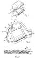
- FIG. 1 is a perspective view of the shell of a catalytic converter of the present invention shown in disassembled relation;
- FIG. 2 is a schematic view of the catalytic converter of FIG. 1, the three-dimensional sinusoidal pattern not being shown for the sake of simplicity;
- FIG. 3 is a schematic end view of the flexible, metal-reinforced intumescent mounting composite; and
- FIG. 4 is a graph illustrating a comparison of pressure (volume stress) applied to a ceramic monolith by the metal-reinforced mounting composite of this invention and mounting mats of the prior art.
- Referring to Figures 1 and 2, a
catalytic converter 10 is shown with ametallic casing 12 having generally frusto-conical inlet andoutlet ends casing 12 is a monolithiccatalytic element 18 formed of a refractory material such as ceramic with gas flow channels contained therein (not shown). Surrounding thecatalytic element 18 is a metal-reinforced, intumescent, mountingcomposite 20 which supports thecatalytic element 18 within thecasing 12. At both ambient temperature and operating temperature, themounting composite 20 holds thecatalytic element 18 in place in thecasing 12 and seals the peripheral edges of thecatalytic element 18 to thus prevent exhaust gases from bypassingcatalytic element 18. Mounting composite 20 comprises an intumescent material formed about a resilient metal reinforcement such as a metal sheet, metal cloth, metal screen or a metal mesh. The resilient metal reinforcement is typically formed of an alloy such as stainless steel, inconel steel, galvanized steel or other metal containing alloys.- During operation of the
catalytic converter 10, the temperature of the assembly increases and the radial gap between thecasing 12 and theceramic element 18 increases due to the high thermal expansion coefficient of thecasing 12. Expansion of themounting composite 20 and its thermal stability and resilience compensate for the difference in thermal expansion of thecasing 12 and thecatalytic element 18 and also protect against vibration of the fragile device. Themounting composite 20 also compensates for irregularities in the metallic or ceramic surfaces. - The metal-reinforced
mounting composite 20 may be formed by standard paper making techniques. From 40 to 65% by weight of treated or untreated flakes of unexpanded vermiculite having particle sizes ranging from about 0.1 mm up to 6 mm, preferably between 1 mm and 2 mm, are combined in a large volume of water with solids in the proportions 25 to 50% inorganic fibrous materials and 5 to 15% of binder. By "treated vermiculite" is meant unexpanded vermiculite ore which has been substantially or completely ion exchanged with NH⁺ cations by treating the vermiculite with ammonium dyhydrogen phosphate, ammonium carbonate, ammonium chloride, ammonium hydroxide or other suitable ammonium compound. The inorganic fibrous materials may comprise alumina-silicate fibers (available commercially under the tradename Fiberfax, Cerafiber and Kaowool), chrysotile or amphibole asbestos, soft glass fibers as available under the tradename Chopped E-glass, refractory filaments including zirconia-silica fibers and crystalline alumina whiskers. Suitable binder for the ceramic monolith mounting composite of this invention can include various polymers and elastomers in latex form, as for example, natural rubber latices, styrene butadiene latices, butadiene acrylonitrile latices, latices of acrylate or methacrylate polymers, copolymers and the like. Inorganic binders can include bentonite or colloidal silica. Organic and inorganic binders may be used in combination to produce sheet materials according to the present invention. Small amounts of surfactants, foaming agents and flocculating agents may also be added before forming the sheet. The above slurry is then introduced around and enclosing a reinforcing material made of stainless steel, inconel, steel, galvanized steel or other suitable metal or metal alloy. - The reinforcing material can be in the form of a sheet, perforated sheet, cloth, screen or mesh. The screen or mesh can be woven, knitted or brazed. This reinforcing material should be crimped, corrugated, zigzagged or otherwise put into a three-dimensional shape so as to provide a resilient, springy material. The preferred shape is seen in FIG. 3 which shows a three dimensional sinusoidal pattern. The reinforcing resilient material should be chosen so that when combined with the slurry and dried, the resulting composite material has a bulk modulus of at least 20 kPa and less than 500 kPa throughout the temperature range of -40 C to 750 C.
- One such reinforcing
material 22 is a knitted wire mesh made of wire having a diameter of .127 to .762 mm, preferably .280 mm, with knitted opening size corresponding to a density of 48 to 100. This density number relates to the spacing of the needles on the knitting machine and is well known in the industry. The wire mesh also has a #12 crimp corresponding to about 1.2 corrugations per centimeter, each corrugation having an amplitude of about 0.64 centimeter. The correct amplitude of the corrugation is critical to achieve the results given in the present invention. The resiliency of the mounting composite is a direct function of the amplitude and spring constant of the reinforcing material. It was found that by providing the knitted wiremesh reinforcing material 22, ring off cracking at high temperatures could be prevented while providing sufficient holding force for the ceramic monolith at low temperatures. Of course, frequency, shape of corrugation and reinforcement type can be varied without departing from the scope of the invention. - Flocculation of the slurry is conveniently achieved using an electrolyte such as alum, alkali or acid. The expanded vermiculite, inorganic fibrous material and organic latex binder are blended together in a volume of water of about 5 to 100 times as much by weight and the flocculating agent or agents are added. A small amount of surfactant or foaming agent may also be employed in order to improve the dispersion of the intumescent material.
- A sheet of composite material is conveniently formed by standard paper-making techniques either in a handsheet former or a Fourdrinier screen. The slurry is preferably introduced such that it penetrates and completely surrounds the reinforcing
material 22 and is dried to formmaterial 21. However, it may also be introduced on either side of or as a shell around the reinforcing material. The resulting green sheet is dewatered and dried at about 90 C to form a handleable, flexible, resilient intumescent ceramic monolith mounting composite sheet material. - The usefulness of the metal-reinforced intumescent mounting composite of the present invention is demonstrated by its ability to generate and maintain sufficient force between the casing and the substrate in order to hold the catalytic ceramic monolith or ceramic diesel particulate filter in the casing over a wide temperature range. This unique holding force is possible despite dimensional changes resulting from differential thermal expansion of the ceramic monolith and metal container. The holding force also responds well at high temperatures and does not generate too much force to subject the ceramic monolith to volume stresses resulting in fractures.
- The following detailed description and tests performed will more fully illustrate the benefits of this invention.
- Water (1200 ml) was poured into a mixing chamber of a large Waring blender and 26 g of alumina-silica fiber (Cerafiber available from Johns-Mansville) was added followed by vigorous agitation for about 15 seconds. The fiber slurry was transferred to a 4 liter beaker and mixed with an air propelled blade. 11 g of Rohm and Haas HA-8 acrylic binder and 43.2 g #4 vermiculite ore (W. R. Grace Co.) were added to the fiber slurry. While mixing, 21.09 g of dilute papermaker's alum (25% solution of aluminum sulfate) and 1.2 g of sodium aluminate were added to the slurry to precipitate the latex binder throughout the other components. The mixture was agitated vigorously and quickly poured onto a handsheet screen on top of which was fixed a piece of knitted wire reinforcement (0.28 mm dia wire, 48 density, #12 crimp stainless steel obtained from Metex Corp.) which was previously degreased in trichloroethylene. The drain was then triggered to dewater the sheet. The composite was then dried on a Williams Apparatus Co. sheet drier.
- Reinforced mounting composites prepared as above, but with varying mount densities, were compared with a conventional intumescent mat (Interam Brand Series IV from 3M Company) and also with the knitted stainless steel mesh alone in an apparatus designed to measure pressure (volume stress) exerted by mounting supports. The apparatus consisted of two stainless steel anvils containing cartridge heaters so that temperatures found in actual catalytic converters could be simulated. The gap or distance between the anvils was set at real converter conditions and the gap increased with rising temperature just as it would in an actual catalytic converter including a five-hour soak, shown in the break area of the graph in FIG. 4. FIG. 4 shows volume stress curves that were generated in this way for the conventional mat C, a knitted wire mesh B and the metal-reinforced intumescent mounting composite A of this invention. (Values are shown in psi.) The conventional mat had poor initial holding force and a high peak force as it expanded. If the conventional mat was compressed more initially to improve the cold holding force, the resulting pressure at high temperature would exceed the strength of the monolith thereby resulting in fracture. The wire mesh alone had good cold holding force but this deteriorated rapidly as the converter was heated. The catalytic converter with the metal-reinforced intumescent mounting composite of the present invention combined a good cold holding force with a lower volume stress peak at high temperature.
- A test to determine how securely the ceramic monolith was held in place in the catalytic converter was conducted by measuring the force required to move the monolith after it had been assembled in the metal housing. The test consisted of mounting a cylindrical ceramic monolith (11.84 cm dia x 15.24 cm long) inside of a metal canister (12.34 cm I.D.). The canister was 2.54 cm longer than the monolith to give the monolith room to move when it was pushed. The force required to move the monolith relative to the canister was measured and thus indicated how tightly the monolith was being held by the mounting material. The force was applied and measured on an MTS tensile tester (MTS Systems Corp.). The maximum push out force is shown in Table 1.
TABLE 1 Mounting Material Mount Density (g/cm³) PUSH OUT FORCE AT Room Temp. (Newtons) 300 C (Newtons) 600 C (Newtons) Reinforced Mounting Composite 0.77 1844 1290 8840 0.96 3032 1209 15720 1.60 9082 5283 >23100 Conventional Mat 0.72 239 86 9560 0.80 475 110 15060 0.88 2008 916 >22960 0.96 2652 1404 >23020 1.04 3077 1475 >23150 Knitted Wire Mesh Not Applicable 823 1056 410 4047 -- 2449 - It will be observed that the metal-reinforced intumescent mounting composite of the present invention avoids extremely low or extremely high push out forces over a much broader mount density range. This is very important in view of the very large monolith tolerances (± 2 mm) typical in catalytic converters resulting in large mount density variations.
- Mounting materials were tested on an exhaust gas simulator (made by RPS Engineering) to determine their ability to prevent ring-off cracking of ceramic catalytic elements mounted in metallic canisters. The metallic canisters were made of 409 stainless steel with an I.D. of 12.34 cm and the ceramic element was a standard ceramic monolith 11.84 cm diameter by 15.24 cm long, 62 cells per square centimeter. The ceramic substrates were wrapped with various mounting materials and connected to the exhaust gas simulator. The exhaust gas simulator, using propane fuel, was run at an inlet gas temperature of 954 C and 23 SCFM. After 10 minutes at 954 C the propane was shut off and room air introduced at 72 SCFM. The air flow was continued until the canister temperature dropped to about 38 C. The unit was disassembled and the substrate examined for cracks. Reinforced mounting composites made according to this invention with wire meshes of different amplitudes were compared with conventional mounting mats made and an intumescent paste "mat" made according to the teaching of U.S. Patent No. 4,269,807. The results of such a comparison are shown in Table 2.
TABLE 2 Mounting Material Mount Density (g/cm³) Results Knitted wire reinforced compositea 0.93 No crack 1.00 No crack 1.10 No crack 1.20 No crack 1.59 No crack Knitted wire reinforced compositeb 1.54 Cracked Corrugated Hex reinforced composite 1.38 No crack Corrugated Wire Cloth reinforced composite 1.04 No crack Conventional Mat 0.80 Cracked 0.92 Cracked 0.98 Cracked 1.36 Several cracks Paste Mat -- Cracked aKnitted wire, 0.011" (.28 mm) diameter 304SS, 48 density, corrugated 0.250" (.64 cm) amplitude, 1/2" (1.27 mm) wavelength. bKnitted wire, 0.011" (28 mm) diameter 304SS, 48 density, corrugated 0.125" (.32 cm) amplitude, 1/2" (1.27 mm) wavelength.
Claims (10)
- A catalytic converter (10) comprising a metallic casing (12), a ceramic catalytic element (18) disposed within the casing (12), and a flexible mounting means (20) disposed between the catalytic element (18) and the metallic casing (12) for positioning the catalytic element (18) and for absorbing mechanical and thermal shock, said flexible mounting means (20) comprising a composite of intumescent material (21) formed about a resilient reinforcing material (22), said catalytic converter (10) characterized by said composite of intumescent material having a bulk modulus greater than 20 kPa and less than 500 kPa throughout the temperature range of -40 °C to 750 °C.
- A catalytic converter (10) as described in claim 1 wherein the flexible mounting means (20) comprises from 40% to 65% by weight of unexpanded vermiculite, from 25% to 50% by weight of inorganic fibrous material and from 5% to 15% of binder.
- A catalytic converter (10) as described in claim 2 wherein said vermiculite has been ion-exchanged with an ammonium compound, and wherein said inorganic fibrous material (21) is asbestos, soft glass fiber, alumina whisker, alumina-silica fiber or zirconia-silica fiber.
- A catalytic converter (10) as described in claim 2 wherein said binder is an organic or inorganic material or combination thereof.
- A catalytic converter (10) as described in claim 1 wherein said resilient reinforcing material (22) is a metal sheet, metal cloth, metal screen or metal mesh.
- A diesel particulate filter (10) comprising a metallic casing (12), a unitary-solid ceramic element (18) disposed within the casing (12), and a flexible mounting means (20) disposed between the ceramic element (18) and the metallic casing (12) for positioning the ceramic element (18) and for absorbing mechanical and thermal shock, said flexible mounting means (20) comprising a composite of intumescent material (21) formed about a resilient reinforcing material (22), said diesel particulate filter (10) characterized by said composite of intumescent material having a bulk modulus greater than 20 kPa and less than 500 kPa throughout the temperature range of -40 C to 750 C.
- A diesel particulate filter (10) as described in claim 6 wherein the flexible mounting means (20) comprises from 40% to 65% by weight of unexpanded vermiculite, from 25% to 50% by weight of inorganic fibrous material and from 5% to 15% of binder.
- A diesel particulate filter (10) as described in claim 7 wherein said vermiculite has been ion-exchanged with an ammonium compound, and wherein said inorganic fibrous material (20) is asbestos, soft glass fiber, alumina whisker, alumina-silica fiber or zirconia-silica fiber.
- A diesel particulate filter (10) as described in claim 7 wherein said binder is an organic or inorganic material or combinations thereof.
- A diesel particulate filter (10) as described in claim 6 wherein said resilient reinforcing material (22) is a metal sheet, metal cloth, metal screen or metal mesh.
Applications Claiming Priority (2)
| Application Number | Priority Date | Filing Date | Title |
|---|---|---|---|
| US12879287A | 1987-12-04 | 1987-12-04 | |
| US128792 | 1987-12-04 |
Publications (3)
| Publication Number | Publication Date |
|---|---|
| EP0319299A2 EP0319299A2 (en) | 1989-06-07 |
| EP0319299A3 EP0319299A3 (en) | 1990-05-02 |
| EP0319299B1true EP0319299B1 (en) | 1992-06-17 |
Family
ID=22436992
Family Applications (1)
| Application Number | Title | Priority Date | Filing Date |
|---|---|---|---|
| EP88311395AExpired - LifetimeEP0319299B1 (en) | 1987-12-04 | 1988-12-01 | Catalytic converter, particulate filter for exhaust systems |
Country Status (6)
| Country | Link |
|---|---|
| EP (1) | EP0319299B1 (en) |
| JP (1) | JPH01190910A (en) |
| KR (1) | KR970001438B1 (en) |
| AU (1) | AU610279B2 (en) |
| CA (1) | CA1310275C (en) |
| DE (1) | DE3872186T2 (en) |
Families Citing this family (54)
| Publication number | Priority date | Publication date | Assignee | Title |
|---|---|---|---|---|
| US5008086A (en)* | 1988-10-28 | 1991-04-16 | Minnesota Mining And Manufacturing Company | Erosion resistant mounting composite for catalytic converter |
| US4999168A (en)* | 1989-05-01 | 1991-03-12 | The Carborundum Company | Crack resistant intumescent sheet material |
| US5213698A (en)* | 1990-07-03 | 1993-05-25 | Exxon Chemical Patents Inc. | Amido-amine ashless dispersants |
| GB9215184D0 (en)* | 1992-07-17 | 1992-09-02 | Alcan Int Ltd | Intumescent systems |
| EP0835230B1 (en)* | 1995-06-30 | 1999-10-27 | Minnesota Mining And Manufacturing Company | Intumescent sheet material |
| US5736109A (en)* | 1995-06-30 | 1998-04-07 | Minnesota Mining And Manufacturing Company | Intumescent sheet material and paste with organic binder |
| US5853675A (en)* | 1995-06-30 | 1998-12-29 | Minnesota Mining And Manufacturing Company | Composite mounting system |
| US5686039A (en)* | 1995-06-30 | 1997-11-11 | Minnesota Mining And Manufacturing Company | Methods of making a catalytic converter or diesel particulate filter |
| US6051193A (en)* | 1997-02-06 | 2000-04-18 | 3M Innovative Properties Company | Multilayer intumescent sheet |
| CN1270056C (en) | 1997-02-06 | 2006-08-16 | 美国3M公司 | Pollution control device |
| GB9716493D0 (en)* | 1997-08-05 | 1997-10-08 | Forber Stephen M | Composite metal mesh and ceramic fibre exhaust gas sealing and support mounting device for use with catalytic converting systems |
| GB9802504D0 (en) | 1998-02-06 | 1998-04-01 | Johnson Matthey Plc | Improvements in emission control |
| US8833062B1 (en) | 2013-03-15 | 2014-09-16 | Daimier Ag | Catalytic reduction of NOx |
| US8404187B1 (en) | 1998-03-11 | 2013-03-26 | Unifrax I Llc | Support element for fragile structures such as catalytic converters |
| GB9915939D0 (en) | 1999-07-08 | 1999-09-08 | Johnson Matthey Plc | Improvements in pollution control |
| US7572415B2 (en) | 2000-03-22 | 2009-08-11 | Ibiden Co., Ltd. | Catalyst converter and diesel, particulate filter system |
| JP4042305B2 (en)* | 2000-06-21 | 2008-02-06 | イビデン株式会社 | Holding seal material for exhaust gas purification catalytic converter |
| KR100371202B1 (en)* | 2000-11-27 | 2003-02-06 | 현대자동차주식회사 | Supporter |
| KR100488690B1 (en)* | 2002-03-06 | 2005-05-11 | 현대자동차주식회사 | Plasma reactor structure for decreasing exhaust gas from vehicles |
| US7550118B2 (en) | 2004-04-14 | 2009-06-23 | 3M Innovative Properties Company | Multilayer mats for use in pollution control devices |
| US7645426B2 (en) | 2004-04-14 | 2010-01-12 | 3M Innovative Properties Company | Sandwich hybrid mounting mat |
| MY148596A (en) | 2004-06-29 | 2013-05-15 | Unifrax Corp | Exhaust gas treatment device and method for making the same |
| JP4688599B2 (en)* | 2005-07-27 | 2011-05-25 | イビデン株式会社 | Holding sealing material and exhaust gas purification device |
| DE202005018611U1 (en) | 2005-11-28 | 2006-02-16 | Schierz, Claus, Dipl.-Ing. | Storage mat for the storage of a catalytic converter |
| US8915064B2 (en) | 2007-05-15 | 2014-12-23 | Donaldson Company, Inc. | Exhaust gas flow device |
| KR101525271B1 (en)* | 2007-07-10 | 2015-06-02 | 쓰리엠 이노베이티브 프로퍼티즈 컴파니 | Pollution control devices, reinforced mat material for use therein and methods of making same |
| US8524161B2 (en) | 2007-08-31 | 2013-09-03 | Unifrax I Llc | Multiple layer substrate support and exhaust gas treatment device |
| BRPI0917717A2 (en) | 2008-08-29 | 2016-02-16 | Unifrax I Llc | Mounting mat with flexible edge guard and exhaust gas treatment device built into the mounting mat. |
| ES2730079T3 (en) | 2008-12-15 | 2019-11-08 | Unifrax I Llc | Honeycomb structure ceramic film cladding |
| WO2010078052A1 (en) | 2008-12-17 | 2010-07-08 | Donaldson Company, Inc. | Flow device for an exhaust system |
| WO2010120380A2 (en) | 2009-04-17 | 2010-10-21 | Unifrax I Llc | Exhaust gas treatment device |
| GB0906837D0 (en) | 2009-04-21 | 2009-06-03 | Saffil Automotive Ltd | Mats |
| CN102713191B (en) | 2009-08-10 | 2016-06-22 | 尤尼弗瑞克斯I有限责任公司 | Variable basis weight mats or preforms and exhaust gas treatment devices |
| CN102575542B (en) | 2009-08-14 | 2014-09-10 | 尤尼弗瑞克斯I有限责任公司 | Mounting mat for exhaust gas treatment device |
| US8071040B2 (en) | 2009-09-23 | 2011-12-06 | Unifax I LLC | Low shear mounting mat for pollution control devices |
| CN104129114B (en) | 2009-09-24 | 2017-01-11 | 尤尼弗瑞克斯 I 有限责任公司 | Multiple-layer mat and exhaust gas treatment device |
| EP2507490B1 (en) | 2009-12-01 | 2017-01-25 | Unifrax Emission Control Europe Ltd. | Mounting mat |
| CN102770630B (en) | 2009-12-17 | 2016-02-17 | 尤尼弗瑞克斯I有限责任公司 | For the multilayer mounting mat of pollution control device |
| JP6129558B2 (en) | 2009-12-17 | 2017-05-17 | ユニフラックス ワン リミテッド ライアビリティ カンパニー | Mounting mat for exhaust gas treatment equipment |
| WO2011084558A1 (en) | 2009-12-17 | 2011-07-14 | Unifrax I Llc | Use of microspheres in an exhaust gas treatment device mounting mat |
| US8539761B2 (en) | 2010-01-12 | 2013-09-24 | Donaldson Company, Inc. | Flow device for exhaust treatment system |
| WO2011163395A1 (en) | 2010-06-22 | 2011-12-29 | Donaldson Company, Inc. | Dosing and mixing arrangement for use in exhaust aftertreatment |
| EP2504536B1 (en) | 2010-08-06 | 2019-03-13 | AVL Test Systems, Inc. | Particulate measurement system |
| WO2012021817A2 (en) | 2010-08-12 | 2012-02-16 | Unifrax I Llc | Exhaust gas treatment device |
| CN103261594B (en) | 2010-08-13 | 2016-01-20 | 尤尼弗瑞克斯I有限责任公司 | There is the emission-control equipment of the edge-protected mounting mat of pliability and merging mounting mat |
| US9120703B2 (en) | 2010-11-11 | 2015-09-01 | Unifrax I Llc | Mounting mat and exhaust gas treatment device |
| US9924564B2 (en) | 2010-11-11 | 2018-03-20 | Unifrax I Llc | Heated mat and exhaust gas treatment device |
| JP5971894B2 (en) | 2011-01-31 | 2016-08-17 | スリーエム イノベイティブ プロパティズ カンパニー | Contamination control element holding material, manufacturing method thereof and contamination control apparatus |
| US8938954B2 (en) | 2012-04-19 | 2015-01-27 | Donaldson Company, Inc. | Integrated exhaust treatment device having compact configuration |
| EP2956233B1 (en) | 2013-02-15 | 2016-12-21 | Donaldson Company, Inc. | Dosing and mixing arrangement for use in exhaust aftertreatment |
| US8850802B1 (en) | 2013-03-15 | 2014-10-07 | Daimler Ag | Catalytic reduction of NOx |
| KR20170118679A (en) | 2015-02-24 | 2017-10-25 | 유니프랙스 아이 엘엘씨 | High temperature resistant insulation mat |
| KR101804783B1 (en) | 2016-03-25 | 2017-12-05 | 현대자동차주식회사 | A vehicle and a method for controlling the same |
| DE102017003778B4 (en) | 2017-04-19 | 2021-11-11 | Andreas Simon | Exhaust filters for automobiles |
Family Cites Families (5)
| Publication number | Priority date | Publication date | Assignee | Title |
|---|---|---|---|---|
| DE2213540C3 (en)* | 1972-03-21 | 1974-06-12 | Zeuna-Staerker Kg, 8900 Augsburg | Catalyst body for cleaning exhaust gases from internal combustion engines and a method for producing this catalyst |
| US4148120A (en)* | 1974-07-16 | 1979-04-10 | Volkswagenwerk Aktiengesellschaft | Method of manufacturing a catalyst for catalytic purification of exhaust gases |
| US4269807A (en)* | 1979-10-22 | 1981-05-26 | Uop Inc. | Catalytic converter mounting arrangement for reducing bypass leakage |
| US4305992A (en)* | 1979-11-28 | 1981-12-15 | Minnesota Mining And Manufacturing Company | Intumescent sheet material |
| DE8019813U1 (en)* | 1980-07-24 | 1980-10-23 | Paul Gillet Gmbh, 6732 Edenkoben | Ceramic swell mat, in particular for storing catalyst blocks in motor vehicle exhaust systems |
- 1988
- 1988-11-14CACA000582923Apatent/CA1310275C/ennot_activeExpired - Lifetime
- 1988-11-15AUAU25145/88Apatent/AU610279B2/ennot_activeCeased
- 1988-12-01DEDE8888311395Tpatent/DE3872186T2/ennot_activeExpired - Fee Related
- 1988-12-01EPEP88311395Apatent/EP0319299B1/ennot_activeExpired - Lifetime
- 1988-12-02JPJP63305876Apatent/JPH01190910A/enactivePending
- 1988-12-03KRKR1019880016157Apatent/KR970001438B1/ennot_activeExpired - Lifetime
Also Published As
| Publication number | Publication date |
|---|---|
| AU2514588A (en) | 1989-06-08 |
| DE3872186T2 (en) | 1993-01-14 |
| JPH01190910A (en) | 1989-08-01 |
| EP0319299A3 (en) | 1990-05-02 |
| CA1310275C (en) | 1992-11-17 |
| KR890009455A (en) | 1989-08-02 |
| AU610279B2 (en) | 1991-05-16 |
| KR970001438B1 (en) | 1997-02-06 |
| DE3872186D1 (en) | 1992-07-23 |
| EP0319299A2 (en) | 1989-06-07 |
Similar Documents
| Publication | Publication Date | Title |
|---|---|---|
| EP0319299B1 (en) | Catalytic converter, particulate filter for exhaust systems | |
| EP0835230B1 (en) | Intumescent sheet material | |
| KR100418111B1 (en) | Methods of making a catalytic converter or diesel particulate filter | |
| US5482686A (en) | Catalytic converter | |
| EP0835229B1 (en) | Intumescent sheet material with glass fibers | |
| CA1304298C (en) | Catalytic converter for automotive exhaust system | |
| CA2353566C (en) | Amorphous non-intumescent inorganic fiber mat for low temperature exhaust gas treatment devices | |
| RU2388522C2 (en) | Device to process exhaust gases and method of its fabrication | |
| US5254410A (en) | Partially dehydrated vermiculite flakes and method of making same | |
| US5151253A (en) | Catalytic converter having a monolith mounting of which is comprised of partially dehydrated vermiculite flakes | |
| CA2321647C (en) | Support element for fragile structures such as catalytic converters | |
| US5028397A (en) | Catalytic converter | |
| EP0972130B1 (en) | Multilayer intumescent sheet | |
| EP0328293A1 (en) | Catalytic converter | |
| EP2513443B1 (en) | Mounting mat for exhaust gas treatment device | |
| EP0095308A1 (en) | Intumescent sheet material containing low density fillers | |
| KR20090053868A (en) | Compositions containing biosoluble inorganic fibers and mica binders | |
| EP2770179A1 (en) | Mat material and exhaust gas purification device | |
| US8404187B1 (en) | Support element for fragile structures such as catalytic converters | |
| JPH06183854A (en) | Heat-resistant molding |
Legal Events
| Date | Code | Title | Description |
|---|---|---|---|
| PUAI | Public reference made under article 153(3) epc to a published international application that has entered the european phase | Free format text:ORIGINAL CODE: 0009012 | |
| AK | Designated contracting states | Kind code of ref document:A2 Designated state(s):DE FR GB IT SE | |
| PUAL | Search report despatched | Free format text:ORIGINAL CODE: 0009013 | |
| AK | Designated contracting states | Kind code of ref document:A3 Designated state(s):DE FR GB IT SE | |
| 17P | Request for examination filed | Effective date:19900823 | |
| 17Q | First examination report despatched | Effective date:19910410 | |
| GRAA | (expected) grant | Free format text:ORIGINAL CODE: 0009210 | |
| AK | Designated contracting states | Kind code of ref document:B1 Designated state(s):DE FR GB IT SE | |
| ITF | It: translation for a ep patent filed | ||
| REF | Corresponds to: | Ref document number:3872186 Country of ref document:DE Date of ref document:19920723 | |
| ET | Fr: translation filed | ||
| PLBE | No opposition filed within time limit | Free format text:ORIGINAL CODE: 0009261 | |
| STAA | Information on the status of an ep patent application or granted ep patent | Free format text:STATUS: NO OPPOSITION FILED WITHIN TIME LIMIT | |
| 26N | No opposition filed | ||
| PGFP | Annual fee paid to national office [announced via postgrant information from national office to epo] | Ref country code:FR Payment date:19931109 Year of fee payment:6 | |
| PGFP | Annual fee paid to national office [announced via postgrant information from national office to epo] | Ref country code:SE Payment date:19931117 Year of fee payment:6 | |
| PGFP | Annual fee paid to national office [announced via postgrant information from national office to epo] | Ref country code:DE Payment date:19931124 Year of fee payment:6 | |
| PGFP | Annual fee paid to national office [announced via postgrant information from national office to epo] | Ref country code:GB Payment date:19931129 Year of fee payment:6 | |
| PG25 | Lapsed in a contracting state [announced via postgrant information from national office to epo] | Ref country code:GB Effective date:19941201 | |
| PG25 | Lapsed in a contracting state [announced via postgrant information from national office to epo] | Ref country code:SE Effective date:19941202 | |
| EAL | Se: european patent in force in sweden | Ref document number:88311395.3 | |
| GBPC | Gb: european patent ceased through non-payment of renewal fee | Effective date:19941201 | |
| PG25 | Lapsed in a contracting state [announced via postgrant information from national office to epo] | Ref country code:FR Effective date:19950831 | |
| PG25 | Lapsed in a contracting state [announced via postgrant information from national office to epo] | Ref country code:DE Effective date:19950901 | |
| EUG | Se: european patent has lapsed | Ref document number:88311395.3 | |
| REG | Reference to a national code | Ref country code:FR Ref legal event code:ST | |
| PG25 | Lapsed in a contracting state [announced via postgrant information from national office to epo] | Ref country code:IT Free format text:LAPSE BECAUSE OF NON-PAYMENT OF DUE FEES;WARNING: LAPSES OF ITALIAN PATENTS WITH EFFECTIVE DATE BEFORE 2007 MAY HAVE OCCURRED AT ANY TIME BEFORE 2007. THE CORRECT EFFECTIVE DATE MAY BE DIFFERENT FROM THE ONE RECORDED. Effective date:20051201 |