EP0318918B2 - Balloon cathether - Google Patents
Balloon cathetherDownload PDFInfo
- Publication number
- EP0318918B2 EP0318918B2EP88119881AEP88119881AEP0318918B2EP 0318918 B2EP0318918 B2EP 0318918B2EP 88119881 AEP88119881 AEP 88119881AEP 88119881 AEP88119881 AEP 88119881AEP 0318918 B2EP0318918 B2EP 0318918B2
- Authority
- EP
- European Patent Office
- Prior art keywords
- balloon
- balloon catheter
- lumen
- inner tube
- tubular body
- Prior art date
- Legal status (The legal status is an assumption and is not a legal conclusion. Google has not performed a legal analysis and makes no representation as to the accuracy of the status listed.)
- Expired - Lifetime
Links
- 230000002787reinforcementEffects0.000claimsdescription23
- 239000000463materialSubstances0.000claimsdescription13
- BASFCYQUMIYNBI-UHFFFAOYSA-NplatinumChemical compound[Pt]BASFCYQUMIYNBI-UHFFFAOYSA-N0.000claimsdescription8
- 229910001252Pd alloyInorganic materials0.000claimsdescription4
- 229910045601alloyInorganic materials0.000claimsdescription4
- 239000000956alloySubstances0.000claimsdescription4
- PCHJSUWPFVWCPO-UHFFFAOYSA-NgoldChemical compound[Au]PCHJSUWPFVWCPO-UHFFFAOYSA-N0.000claimsdescription4
- 229910052737goldInorganic materials0.000claimsdescription4
- 239000010931goldSubstances0.000claimsdescription4
- SWELZOZIOHGSPA-UHFFFAOYSA-Npalladium silverChemical compound[Pd].[Ag]SWELZOZIOHGSPA-UHFFFAOYSA-N0.000claimsdescription4
- 229910052697platinumInorganic materials0.000claimsdescription4
- WFKWXMTUELFFGS-UHFFFAOYSA-NtungstenChemical compound[W]WFKWXMTUELFFGS-UHFFFAOYSA-N0.000claimsdescription4
- 229910052721tungstenInorganic materials0.000claimsdescription2
- 239000010937tungstenSubstances0.000claimsdescription2
- 210000004204blood vesselAnatomy0.000description29
- 239000002872contrast mediaSubstances0.000description16
- 238000002347injectionMethods0.000description10
- 239000007924injectionSubstances0.000description10
- 208000031481Pathologic ConstrictionDiseases0.000description9
- 238000002399angioplastyMethods0.000description9
- 230000036262stenosisEffects0.000description9
- 208000037804stenosisDiseases0.000description9
- 230000003902lesionEffects0.000description7
- -1polyethylenePolymers0.000description7
- 229920005992thermoplastic resinPolymers0.000description7
- 230000001154acute effectEffects0.000description6
- 239000008280bloodSubstances0.000description5
- 210000004369bloodAnatomy0.000description5
- 229920000098polyolefinPolymers0.000description5
- 239000004952PolyamideSubstances0.000description4
- 238000002594fluoroscopyMethods0.000description4
- 229920001200poly(ethylene-vinyl acetate)Polymers0.000description4
- 229920002647polyamidePolymers0.000description4
- 230000002792vascularEffects0.000description4
- 239000004698PolyethyleneSubstances0.000description3
- 230000009977dual effectEffects0.000description3
- 229920001971elastomerPolymers0.000description3
- 239000000806elastomerSubstances0.000description3
- 230000001747exhibiting effectEffects0.000description3
- 229920000126latexPolymers0.000description3
- 230000002093peripheral effectEffects0.000description3
- 229920000573polyethylenePolymers0.000description3
- 229920002635polyurethanePolymers0.000description3
- 239000004814polyurethaneSubstances0.000description3
- 239000004800polyvinyl chlorideSubstances0.000description3
- 229920000915polyvinyl chloridePolymers0.000description3
- 229920002379silicone rubberPolymers0.000description3
- 239000004945silicone rubberSubstances0.000description3
- 229920001577copolymerPolymers0.000description2
- 210000004351coronary vesselAnatomy0.000description2
- 230000000916dilatatory effectEffects0.000description2
- 239000007788liquidSubstances0.000description2
- 238000000034methodMethods0.000description2
- 230000003014reinforcing effectEffects0.000description2
- FDSYTWVNUJTPMA-UHFFFAOYSA-N2-[3,9-bis(carboxymethyl)-3,6,9,15-tetrazabicyclo[9.3.1]pentadeca-1(15),11,13-trien-6-yl]acetic acidChemical compoundC1N(CC(O)=O)CCN(CC(=O)O)CCN(CC(O)=O)CC2=CC=CC1=N2FDSYTWVNUJTPMA-UHFFFAOYSA-N0.000description1
- 208000032843HemorrhageDiseases0.000description1
- 206010061876ObstructionDiseases0.000description1
- 239000000853adhesiveSubstances0.000description1
- 230000001070adhesive effectEffects0.000description1
- 238000005452bendingMethods0.000description1
- 238000004891communicationMethods0.000description1
- 238000007887coronary angioplastyMethods0.000description1
- 239000005038ethylene vinyl acetateSubstances0.000description1
- 239000012530fluidSubstances0.000description1
- 230000004927fusionEffects0.000description1
- 238000003780insertionMethods0.000description1
- 230000037431insertionEffects0.000description1
- 229920002492poly(sulfone)Polymers0.000description1
- 239000004417polycarbonateSubstances0.000description1
- 229920000515polycarbonatePolymers0.000description1
- 230000000007visual effectEffects0.000description1
- 238000004804windingMethods0.000description1
Images


Classifications
- A—HUMAN NECESSITIES
- A61—MEDICAL OR VETERINARY SCIENCE; HYGIENE
- A61M—DEVICES FOR INTRODUCING MEDIA INTO, OR ONTO, THE BODY; DEVICES FOR TRANSDUCING BODY MEDIA OR FOR TAKING MEDIA FROM THE BODY; DEVICES FOR PRODUCING OR ENDING SLEEP OR STUPOR
- A61M25/00—Catheters; Hollow probes
- A61M25/10—Balloon catheters
- A61M25/104—Balloon catheters used for angioplasty
- A—HUMAN NECESSITIES
- A61—MEDICAL OR VETERINARY SCIENCE; HYGIENE
- A61M—DEVICES FOR INTRODUCING MEDIA INTO, OR ONTO, THE BODY; DEVICES FOR TRANSDUCING BODY MEDIA OR FOR TAKING MEDIA FROM THE BODY; DEVICES FOR PRODUCING OR ENDING SLEEP OR STUPOR
- A61M25/00—Catheters; Hollow probes
- A61M25/0043—Catheters; Hollow probes characterised by structural features
- A61M25/005—Catheters; Hollow probes characterised by structural features with embedded materials for reinforcement, e.g. wires, coils, braids
- A61M25/0052—Localized reinforcement, e.g. where only a specific part of the catheter is reinforced, for rapid exchange guidewire port
- A—HUMAN NECESSITIES
- A61—MEDICAL OR VETERINARY SCIENCE; HYGIENE
- A61M—DEVICES FOR INTRODUCING MEDIA INTO, OR ONTO, THE BODY; DEVICES FOR TRANSDUCING BODY MEDIA OR FOR TAKING MEDIA FROM THE BODY; DEVICES FOR PRODUCING OR ENDING SLEEP OR STUPOR
- A61M25/00—Catheters; Hollow probes
- A61M2025/0004—Catheters; Hollow probes having two or more concentrically arranged tubes for forming a concentric catheter system
Definitions
- This inventionrelates to a balloon catheter. More particularly, it relates to a balloon catheter for expanding and thereby remedying stenosis in the blood vessel for improving the state of the distal side blood stream.
- percutaneous transuminal angioplastyPTA
- percutaneous transluminal coronary angioplastyPTCA
- a fine guide wireis passed through the vessel.
- a catheter having an end balloon (expandable member)is introduced into the vessel , using this guide wire as the guide, until the balloon is positioned at the site of lesion where stenosis or obturation has occurred.
- a liquid such as contrast mediumis injected continuously into the balloon via an end hub under a pressure of several to ten atmospheres for dating the balloon towards the inner wall of the blood vessel for pressuring and thereby enlarging the narrowed or obturated sites.
- a balloon catheterhaving a coaxial dual tube system including an inner tube opened at one end and defining a first lumen and an outer tube surrounding the inner tube, forming a second lumen with the inner tube and provided with a distal balloon, or one in which a tubular member defining a lumen is provided with a distal balloon surrounding the end of the tubular member.
- ring markers formed of an X-ray opaque materialare provided at predetermined portions of the inner tube in the balloon that are substantially in register with both ends of the balloon, those ring markers being used as means for identifying the cylindrical portion of the balloon under X-ray fluoroscopy.
- the riskis high that the inner tube disposed within the balloon at the bends of the blood vessel be broken and collapsed the lumen opened at one end to obstruct smooth progress of the guide wire,
- a balloon catheterin which a piping having at both ends thereof prescribed portions substantially in register with both ends of the cylindrical portion of the balloon is provided on the inner tube disposed within the balloon. While it is possible with this known balloon catheter to prevent the inner tube from being broken and collapsed, it is difficult for the balloon catheter to proceed through the inside of the blood vessel presenting acute band or bends. Even supposing that the balloon catheter should have succeeded in proceeding beyond the bend, the risk is high that the piping remains bent to obstruct the progress thereof the blood vessel beyond the bend towards the distal side of the vascular system.
- US-A-4 597 755shows a balloon catheter having a reinforcing coil located inside of the inner tube
- a balloon cathetercomprising a tubular body including at least one lumen, a foldable balloon provided at a predetermined distal portion on the outer surface of said tubular body so that the balloon communicates with at least one lumen in said tubular body, said balloon having a cylindrical section, and a coil spring reinforcement formed of an X-ray opaq material extending only on a portion of said tubular body which is in register with the cylindrical section wherein the lumen has a constant inner diameter in the portion surrounded by the balloon and said coil spring reinforcement is only wound on the outer surface of said tubular body surrounded by said balloon at said portion of the tubular body in register with said cylindrical section.
- the diameter of a portion of the balloon catheter which is introduced into the patient's body and which is formed by said tubular body and the folded balloonis preferably more than 2.7 mm.
- the X-ray opaque materialbe platinum, gold, tungstene or alloys thereof.
- the opaque materialbe a silver-palladium alloy.
- the reinforcementbe made of a wire having a circular, rectangular or an elliptical cross-section.
- the wirehas turns thereof in intimate and tight contact with one another.
- turns of the coil springmay be arranged thick in both end parts and thin in the intermediate part of the coil spring.
- the portions of the balloon catheter surrounded by the balloonmay be prevented from being broken and collapsed, even when the catheter is proceeding through the inside of the blood vessel presenting acute bend or bends, so that the balloon catheter can be proceeded positively to the site of lesion in the blood vessel.
- Figs.1 to 4illustrate a preferred embodiment of the balloon catheter according to the present invention.
- Fig.1is an enlarged sectional view showing the distal side of the balloon catheter.
- Figs.2 and 3are sectional views taken along line II-II and line III-III of Fig.1, respectively.
- Fig.4is an enlarged sectional view showing the proximal side of the balloon catheter.
- the balloon catheter 10 of the present inventionincludes an inner tube 1 having a first lumen opened at one end, an outer tube 2 provided for encircling the inner tube 1 at a position set back a predetermined distance from a foremost part 1a of the inner tube 1 and defining a second lumen 6 between it and the outer surface of the inner tube 1, and a balloon 3 including a distal end 7 attached to the inner tube 1 and a proximal end 8 attached to the outer tube 2.
- the balloon 3communicates with the second lumen in the vicinity of the proximal end 8. and has a cylindrical section 3a, can be including at least a portion thereof substantially cylindrical in contour to permit a constricted site of the blood vessel to be dilated easily.
- a spring coil reinforcement 9is wound about a portion on the outer peripheral surface of the inner tube which is in register with the cylindrical section 3a.
- the balloon catheter 10has the inner tube 1 and the outer tube 2 as a cathether tube or tubular body or member 5, the proximal end of which is provided with a bifurcated branched hub 20, as shown in Fig.4.
- the branched hub 20has a guide wire port 12 and an injection port 13 communicating with the first lumen 4 and with the second lumen 6, respectively.
- the first lumen 4 formed by the inner tube 1plays the role of a guide wire passage and a blood route or channel during use of the balloon catheter.
- the first lumencommunicates at its proximal end with the guide wire port 12 formed in the branched hub 20, such that a guide wire 15 for the balloon catheter as later described is introduced into an opening end of the guide wire port 12 so as to be guided into the first lumen 4.
- the inner tube 1is formed of a material exhibiting certain flexibility, including polyolefins, such as polyethylene, polypropylene, ethylene-propylene copolymers or ethylene-vinyl acetate copolymers, thermoplastic resins, such as polyvinyl chloride, polyamide elastomers or polyurethane, silicone rubber or latex rubber. More preferred are the aforementioned thermoplastic resins and most preferred are polyolefins.
- polyolefinssuch as polyethylene, polypropylene, ethylene-propylene copolymers or ethylene-vinyl acetate copolymers
- thermoplastic resinssuch as polyvinyl chloride, polyamide elastomers or polyurethane, silicone rubber or latex rubber. More preferred are the aforementioned thermoplastic resins and most preferred are polyolefins.
- the outer tube 2, in the inside of which the inner tube 1 is introduced,is preferably mounted coaxially with the inner tube 1 and at a position in which the foremost part of the outer tube is set back a small distance from the foremost part 1a of the inner tube 1.
- the second lumen 6is defined between the inner surface of the outer tube 2 and the outer surface of the inner tube 1.
- the second lumen 6plays the role of a channel for injection of, for example, contrast medium and dischaging of residual air and communicates at its proximal end with the injection port 13 of the branched hub 20.
- the second lumen 6also communicates at its distal end with the inside of the balloon 3 at its rear end.
- the contrast mediumfor example, are injected and charged into the internal space of the balloon 3 via the opening end of the injection port 13 and the second lumen 6 while the residual air is discharged simultaneously.
- the outer tube 2is formed of a material exhibiting certain flexibility, including polyolefins, such as polyethylene, polypropylene, ethylene-propylene copolymers or ethylene-vinyl acetate copolymers, thermoplastic resins, such as polyvinyl chloride, polyamide elastomers or polyurethane, silicone rubber or latex rubber, More preferred are the aforememtioned thermoplastic resins and most preferred are polyolefins.
- polyolefinssuch as polyethylene, polypropylene, ethylene-propylene copolymers or ethylene-vinyl acetate copolymers
- thermoplastic resinssuch as polyvinyl chloride, polyamide elastomers or polyurethane, silicone rubber or latex rubber. More preferred are the aforememtioned thermoplastic resins and most preferred are polyolefins.
- the balloon 3has its foremost part 7 and rear end 8 secured to the outer peripheral surface of the foremost part of the inner tube 1 and to the outer peripheral surface of the foremost part of the outer tube 2 liquid-tightly, respectively, as with an adhesive or by heat fusion, for delimiting an expansion space 14 between the inner surface of the balloon 3 and the outer surface of the inner tube 1.
- This expansion space 14communicates at its rear end with the second lumen 6 along its overall periphery so that the contrast medium, for example, may be charged into the space 14 via the second lumen 6, as described hereinabove.
- the balloon 3may be folded in such a manner that, when the balloon is not dilated, it may be folded and wrapped about the outer periphery of the inner tube 1.
- at least a portion of the balloon 3is formed as a substantially equidiametral cylinder for defining the aforementioned cylindrical section 3a.
- the cylindrical sectionneed not be a true cylinder but may be in the form of a prism having a polygonal cross-section.
- the balloon 3is tapered from the forward side of the cylindrical section 3a to the foremost part 7 where it is secured to the inner tube 1 and from the rear side of the cylindrical section 3a to the rear end 8 where it is secured to the outer tuba 2.
- the portion of the balloon catheter introduced into the patient's bodybe of an outside diameter of not more than 2.7 mm at the maximum, since the balloon catheter can be used satisfactorily in such case in the body cavity, above all, in a finer vasculum.
- the balloon 3is preferably formed of a material exhibiting certain flexibility, including polyolefins, such as polyethylene, polypropylene, ethylene-propylene copolymers, ethylene-vinyl acetate copolymers or cross-linked ethylene-vinyl acetate copolymer, thermoplastic resins, such as polyvinyl chloride, polyamide elastomers or polyurethane, silicone rubber or latex rubber. More preferred are the aforememtioned thermoplastic resins and most preferred are the cross-linked ethlene-vinyl acetate copolymers
- a coil spring reinforcement 9is wound about a predetermined portion of the outer surface of the inner tube 1 which is enclosed within the balloon 3, and in register with the aforementioned cylindrical section 3a. so that the coil spring reinforcement extends only on the portion of inner tube 1 in register with cylindrical section 3a.
- the reinforcement 9 thus wound about the inner tube 1the inner tube is rendered more resistant against buckling, so that there is no risk that the inner tube 1 disposed in the balloon 3 be broken or the first lumen 4 through which the guide wire 15 for the balloon catheter is passed be broken even at a bend of the blood vessel.
- the reinforcement 9is formed of an X-ray opaque material, preferably platinum, gold, tungsten or alloys thereof and more preferably a silver-palladium alloy, since a clear contrast image can then be obtained under X-ray fluoroscopy and thus the cylindrical section 3a of the balloon 3 can be identified more easily.
- the coil spring reinforcement 9is preferably made of a wound wire. By using the coil spring as the reinforcement, the inner tube 1 can be reinforced more strongly against buckling.
- the wire of the coil springpreferably has a circular, rectangular or an elliptical cross-section for inceasing reinforcing effects.
- the wire in the form of a coil springis preferably so wound that its turns are in intimate contact with one another. With this dense winding of the wire, the inner tube can be reinforced more strongly against buckling.
- the branched hub 20is formed by an inner tube hub 22 and an outer tube hub 23.
- the inner tube hub 22communicates with the first lumen 4, has a guide wire port 12 through which the guide wire 15 for the balloon catheter is introduced, and is secured to the inner tube 1.
- the outer tube hub 23communicates with the second lumen 6, has an injection port 13 for injecting contrast medium, for example, and is secured to the outer tube 2.
- the outer tube hub 23 and the inner tube hub 22are secured to each other.
- the branched hub 20is preferably formed of thermoplastic resins, such as, for example, polycarbonate, polyamide, polysulfone, polyallylate or methacrylate-butylene-stylene copolymers.
- suction and injection meanssuch as a in-deflator, filled with contrast medium is attached to the injection port 13 of the catheter and the operation of alternate injection and suction is repeatedly performed to remove the air in the second lumen 6 and the balloon 3 to replace it with the contrast medium.
- a blood vessel 30is procured, that is, peirced with the dilater and sheath 25 as shown in Fig.6, by relying upon, for example, the Sheath method.
- a guiding catheter indwelled guide wireis prepared.
- a guiding catheter 26is introduced into the blood vessel 30 along the guide wire and left at an inlet 31 to the coronary artery having a target lesion. The guide wire for the guide catheter is then removed.
- the balloon catheter guide wire 15is then introduced at the guide wire port 12 of the balloon catheter 10 into the inner tubs 1 of the tubular member 5, that is, into the first lumen 4, until the guide wire is protruded several centimeters beyond the end opening 1a of the inner tube 1, as indicated in Fig.5.
- the resulting assemblyis than introduced into the guiding catheter 26 via a balloon catheter port 28 of a Y-shaped connector 27, to the proximal end of which the guiding catheter 26 is connected, as shown in Fig.6.
- the balloon catheter 10is then proceeded through the inside of the guiding catheter 26 so as to be proceeded via the forward end of the guiding catheter 26 into the blood vessel 30 having the target lesion 30.
- the balloon catheter guide wire 15is then extended to the target lesion through the inside of the blood vessel 30, as shown in Fig.8.
- the guide wire 15is left in the blood vessel after it has passed through the constricted site 32.
- the balloon catheter 10is then advanced through the inside of the blood vessel 30 along the balloon catheter guide wire 15.
- the balloon catheter 10 of the present inventionhas an increased resistance against bending since the reinforcement 9 is wound about the portion of the outer surface of the inner tube 1 disposed within the balloon 3, so that, even when the blood vessel 30 has an acute bend, as shown in Fig.8, there is no risk of obstruction of the progress of the balloon catheter guide wire 15 caused by the breaking of the inner tube 1 within the balloon 3 or the collapse of the first lumen opened at the end and hence the balloon catheter 10 can be proceeded smoothly towards the lesion at the distal side.
- the reinforcement 9is formed as a wire in the form of a coil spring, which is wound about the outer surface of the inner tube 1 with the neighboring turns of the coil in tight and intimate contact with one another, an increased resistance is obtained against external forces.
- the coil wirehas an elliptical, rectangular or a circular cross-section, a further increase is obtained in the resistance against external forces.
- the reinforcement 9is formed of an X-ray opague material
- the reinforcement 9is indicated as a clear X-ray contrast image, under X-ray fluoroscopy, such that this reinforcement 9 can be checked visually as an indicia for the balloon for positively positioning the cylindrical section 3a of the balloon 3 at the stenosis site 32.
- the X-ray opaque materialbe platinum, gold, tungstene, alloys thereof or a silver-palladium alloy, since then a clearer X-ray contrast image is produced and thus the reinforcement may be used more effectively as the indicia for the balloon 3.
- the portion of the balloon catheter introduced into the patient's bodybe of an outside diameter of not more than 2.7 mm, since then the balloon catheter can be used more advantageously within the body cavity, above all, within the vessel having a narrower inner cavity.
- the contrast mediumare injected into the dilated space 14 of the balloon 3, as the contrast medium are pressurized to several to ten and odds atmospheres, by the injector fitted with a pressure gauge 24, connected to the injection port 13 of the balloon catheter 10, for expanding the balloon 3 as shown in Fig.10 for pressuring and enlarging the diameter of the stenosis site 32.
- the contrast mediumare injected into the blood vessel via contrast medium injection port 29 of the Y-shaped connector 27 connected to the proximal end of the guiding catheter 26 for visual checking of the distal side blood stream by X-ray fluoroscopy.
- the balloon catheter 10 and the balloon catheter guide wire 15are removed from the blood vessel 30.
- the guiding catheter 26is then removed and the pierced portion of the blood vessel is pressed to stop the hemorrhage to terminate the operation.
- the above described balloon catheteris formed by coaxially arranged inner and outer tubes defining two lumens.
- the present inventionmay naturally be applied to a balloon catheter formed by a tubular member defining a sole lumen.
- a balloon 3' enclosing the distal part of a tubular member 5'is provided at the distal part of the tubular member 5' defining the sole lumen 6'.
- the reinforcement 9is provided at the distal part of the tubular member 5' surrounded by the balloon 3' for forming a balloon catheter 10'.
- This balloon catheter 10'is used for improving the state of stenosis of the coronary artery, for example.
- the operation of the balloon catheter 10'is basically the same as that of the above described balloon catheter 10 having the dual tube structure.
- the balloon catheter guide wire 15is introduced into the lumen 6' at its proximal end and held so that its distal part does not break the balloon 3'. In this state, the air inside the balloon 3' is replaced by the contrast medium in the same way as in the preceding embodiment.
- the contrast mediumare then sucked and discharged in a predetermined amount using the aforementioned in-deflator to cause the balloon 3' to be wrapped about the tubular member 5' to reduce the outside diameter of the balloon 3' so that the outside diameter of the portion introduced into the balloon catheter 10' is not more than 2.7 mm.
- a tubular member 5'' defining a sole lumen 6''has a distal closed end.
- a balloon 3''enclosing the distal part of the tubular member 5''.
- the lumen 6'' of the tubular member 5''is in fluid communication with an expansion space 14'' of the balloon 3'' through an orifice or orifices formed in the tubular member 5''.
- the reinforcement 9is provided at the distal part of the tubular member 5'' surrounded by the balloon 3'' and have turns thereof so wound that they be in intimate contact with each other.
- the operation of this balloon catheteris substantially same as those of the above-discribed balloon catheters.
- the coil spring reinforcementmay alternatively be so wound that its turns are thick for example in intimate contact with each other in both end parts and thin or sparse in the intermediate part of the coil spring.
- the balloon catheter in this stateis introduced into the blood vessel 30, as it is guided by the balloon catheter guide wire 15, until the balloon 3' reaches the stenosis site 32 in the same way as in the preceding embodiment.
- the contrast mediumare then injected in a predetermined amount into the expansion space 14' of the balloon 3', with the aid of the pressure gauge-injector 24, for dilating the balloon 3' for pressuring and enlarging the stenosis 32.
- the balloon catheter 10'may be removed from the inside of the blood vessel, as described hereinabove.
- the tubular membercan be reinforced against buckling.
- the balloon portion of the balloon cathertermay positively be proceeded to the target lesion, without breaking and collapsing of the tube portion enclosed in the balloon even at progress through an acute bend of the blood vessel.
Landscapes
- Health & Medical Sciences (AREA)
- Life Sciences & Earth Sciences (AREA)
- Heart & Thoracic Surgery (AREA)
- Anesthesiology (AREA)
- Hematology (AREA)
- Biophysics (AREA)
- Pulmonology (AREA)
- Engineering & Computer Science (AREA)
- Veterinary Medicine (AREA)
- Biomedical Technology (AREA)
- Public Health (AREA)
- Animal Behavior & Ethology (AREA)
- General Health & Medical Sciences (AREA)
- Child & Adolescent Psychology (AREA)
- Vascular Medicine (AREA)
- Media Introduction/Drainage Providing Device (AREA)
- Radiation-Therapy Devices (AREA)
Description
- This invention relates to a balloon catheter. More particularly, it relates to a balloon catheter for expanding and thereby remedying stenosis in the blood vessel for improving the state of the distal side blood stream.
- In the event of stenosis or obturations in the vascular system, such as blood vessels, percutaneous transuminal angioplasty (PTA) or percutaneous transluminal coronary angioplasty (PTCA) is performed for enlarging or recanalizing the narrowed or obturated site of the vascular system to thereby improve the body liquid stream towards the distal side of the vascular system. In PTA or PTCA, after a blood vessel is procured percutaneously, a fine guide wire is passed through the vessel. A catheter having an end balloon (expandable member) is introduced into the vessel , using this guide wire as the guide, until the balloon is positioned at the site of lesion where stenosis or obturation has occurred. A liquid such as contrast medium is injected continuously into the balloon via an end hub under a pressure of several to ten atmospheres for dating the balloon towards the inner wall of the blood vessel for pressuring and thereby enlarging the narrowed or obturated sites.
- As a balloon catheter employed in PTA or PTCA, there is known a balloon catheter having a coaxial dual tube system including an inner tube opened at one end and defining a first lumen and an outer tube surrounding the inner tube, forming a second lumen with the inner tube and provided with a distal balloon, or one in which a tubular member defining a lumen is provided with a distal balloon surrounding the end of the tubular member.
- In the case of the former balloon catheter having the coaxial dual tube system, ring markers formed of an X-ray opaque material are provided at predetermined portions of the inner tube in the balloon that are substantially in register with both ends of the balloon,, those ring markers being used as means for identifying the cylindrical portion of the balloon under X-ray fluoroscopy. However, considering that the balloon catheter is caused to proceed through the inside of the blood vessel presenting acute bend or bends, the risk is high that the inner tube disposed within the balloon at the bends of the blood vessel be broken and collapsed the lumen opened at one end to obstruct smooth progress of the guide wire,
- For overcoming the above difficulties, there is also known a balloon catheter in which a piping having at both ends thereof prescribed portions substantially in register with both ends of the cylindrical portion of the balloon is provided on the inner tube disposed within the balloon. While it is possible with this known balloon catheter to prevent the inner tube from being broken and collapsed, it is difficult for the balloon catheter to proceed through the inside of the blood vessel presenting acute band or bends. Even supposing that the balloon catheter should have succeeded in proceeding beyond the bend, the risk is high that the piping remains bent to obstruct the progress thereof the blood vessel beyond the bend towards the distal side of the vascular system.
- Further, US-A-4 597 755 shows a balloon catheter having a reinforcing coil located inside of the inner tube
- It is a principal object of the prevent invention to provide a balloon catheter which is free from the above problems of the prior art and which is able to prevent breaking of the inner tube and obstructing of the lumen in blood vessels presenting an acute bend or bends.
- According to the present invention, there is provided a balloon catheter comprising a tubular body including at least one lumen, a foldable balloon provided at a predetermined distal portion on the outer surface of said tubular body so that the balloon communicates with at least one lumen in said tubular body, said balloon having a cylindrical section, and a coil spring reinforcement formed of an X-ray opaq material extending only on a portion of said tubular body which is in register with the cylindrical section wherein the lumen has a constant inner diameter in the portion surrounded by the balloon and said coil spring reinforcement is only wound on the outer surface of said tubular body surrounded by said balloon at said portion of the tubular body in register with said cylindrical section.
- The diameter of a portion of the balloon catheter which is introduced into the patient's body and which is formed by said tubular body and the folded balloon is preferably more than 2.7 mm.
- It is preferred that the X-ray opaque material be platinum, gold, tungstene or alloys thereof.
- It is preferred that the opaque material be a silver-palladium alloy.
- It is preferred that the reinforcement be made of a wire having a circular, rectangular or an elliptical cross-section.
- It is also preferred that the wire has turns thereof in intimate and tight contact with one another.
- Alternatively, turns of the coil spring may be arranged thick in both end parts and thin in the intermediate part of the coil spring.
- According to the present invention, the portions of the balloon catheter surrounded by the balloon may be prevented from being broken and collapsed, even when the catheter is proceeding through the inside of the blood vessel presenting acute bend or bends, so that the balloon catheter can be proceeded positively to the site of lesion in the blood vessel.
- Some examples of the present invention will now be described with reference to the accompanying drawings in which
- Fig.1 is an enlarged sectional view showing the distal end part of the balloon catheter according to a preferred embodiment of the present invention,
- Fig.2 is a sectional view taken along line II-II of Fig.1,
- Fig.3 is a sectional view taken along line III-III of Fig.1,
- Fig.4 is a diagrammatic view showing the proximal end part of the balloon catheter shown in Fig.1,
- Fig.5 is an overall aide view showing the balloon catheter of Fig.1, with a portion thereof being broken away,
- Figs.6 to 10 are diagrammatic views for illustrating the operation of the balloon catheter shown in Fig.1, and
- Figs.11 and 12 are enlarged sectional views showing the distal end part of balloon catheters according to modified embodiments of the present invention.
- Figs.1 to 4 illustrate a preferred embodiment of the balloon catheter according to the present invention. Fig.1 is an enlarged sectional view showing the distal side of the balloon catheter. Figs.2 and 3 are sectional views taken along line II-II and line III-III of Fig.1, respectively. Fig.4 is an enlarged sectional view showing the proximal side of the balloon catheter.
- As shown in Figs.1 to 4, the
balloon catheter 10 of the present invention includes aninner tube 1 having a first lumen opened at one end, anouter tube 2 provided for encircling theinner tube 1 at a position set back a predetermined distance from aforemost part 1a of theinner tube 1 and defining asecond lumen 6 between it and the outer surface of theinner tube 1, and aballoon 3 including a distal end 7 attached to theinner tube 1 and aproximal end 8 attached to theouter tube 2. Theballoon 3 communicates with the second lumen in the vicinity of theproximal end 8. and has acylindrical section 3a, can be including at least a portion thereof substantially cylindrical in contour to permit a constricted site of the blood vessel to be dilated easily. A spring coil reinforcement 9 is wound about a portion on the outer peripheral surface of the inner tube which is in register with thecylindrical section 3a. - The
balloon catheter 10 has theinner tube 1 and theouter tube 2 as a cathether tube or tubular body ormember 5, the proximal end of which is provided with a bifurcatedbranched hub 20, as shown in Fig.4. Thebranched hub 20 has aguide wire port 12 and aninjection port 13 communicating with thefirst lumen 4 and with thesecond lumen 6, respectively. - The
first lumen 4 formed by theinner tube 1 plays the role of a guide wire passage and a blood route or channel during use of the balloon catheter. The first lumen communicates at its proximal end with theguide wire port 12 formed in thebranched hub 20, such that aguide wire 15 for the balloon catheter as later described is introduced into an opening end of theguide wire port 12 so as to be guided into thefirst lumen 4. - The
inner tube 1 is formed of a material exhibiting certain flexibility, including polyolefins, such as polyethylene, polypropylene, ethylene-propylene copolymers or ethylene-vinyl acetate copolymers, thermoplastic resins, such as polyvinyl chloride, polyamide elastomers or polyurethane, silicone rubber or latex rubber. More preferred are the aforementioned thermoplastic resins and most preferred are polyolefins. - The
outer tube 2, in the inside of which theinner tube 1 is introduced, is preferably mounted coaxially with theinner tube 1 and at a position in which the foremost part of the outer tube is set back a small distance from theforemost part 1a of theinner tube 1. Thesecond lumen 6 is defined between the inner surface of theouter tube 2 and the outer surface of theinner tube 1. Thesecond lumen 6 plays the role of a channel for injection of, for example, contrast medium and dischaging of residual air and communicates at its proximal end with theinjection port 13 of thebranched hub 20. Thesecond lumen 6 also communicates at its distal end with the inside of theballoon 3 at its rear end. The contrast medium, for example, are injected and charged into the internal space of theballoon 3 via the opening end of theinjection port 13 and thesecond lumen 6 while the residual air is discharged simultaneously. - The
outer tube 2 is formed of a material exhibiting certain flexibility, including polyolefins, such as polyethylene, polypropylene, ethylene-propylene copolymers or ethylene-vinyl acetate copolymers, thermoplastic resins, such as polyvinyl chloride, polyamide elastomers or polyurethane, silicone rubber or latex rubber, More preferred are the aforememtioned thermoplastic resins and most preferred are polyolefins. - The
balloon 3 has its foremost part 7 andrear end 8 secured to the outer peripheral surface of the foremost part of theinner tube 1 and to the outer peripheral surface of the foremost part of theouter tube 2 liquid-tightly, respectively, as with an adhesive or by heat fusion, for delimiting anexpansion space 14 between the inner surface of theballoon 3 and the outer surface of theinner tube 1. Thisexpansion space 14 communicates at its rear end with thesecond lumen 6 along its overall periphery so that the contrast medium, for example, may be charged into thespace 14 via thesecond lumen 6, as described hereinabove. - The
balloon 3 may be folded in such a manner that, when the balloon is not dilated, it may be folded and wrapped about the outer periphery of theinner tube 1. In order that the constricted site of the blood vessel may be dilated more easily, at least a portion of theballoon 3 is formed as a substantially equidiametral cylinder for defining the aforementionedcylindrical section 3a. The cylindrical section need not be a true cylinder but may be in the form of a prism having a polygonal cross-section. - It should be noted that the
balloon 3 is tapered from the forward side of thecylindrical section 3a to the foremost part 7 where it is secured to theinner tube 1 and from the rear side of thecylindrical section 3a to therear end 8 where it is secured to theouter tuba 2. - It should also be noted that, in the state in which the
balloon 3 is folded and wrapped about theinner tube 1, that is, theballoon 3 is wrapped around thecatheter tube 5, the portion of the balloon catheter introduced into the patient's body be of an outside diameter of not more than 2.7 mm at the maximum, since the balloon catheter can be used satisfactorily in such case in the body cavity, above all, in a finer vasculum. - The
balloon 3 is preferably formed of a material exhibiting certain flexibility, including polyolefins, such as polyethylene, polypropylene, ethylene-propylene copolymers, ethylene-vinyl acetate copolymers or cross-linked ethylene-vinyl acetate copolymer, thermoplastic resins, such as polyvinyl chloride, polyamide elastomers or polyurethane, silicone rubber or latex rubber. More preferred are the aforememtioned thermoplastic resins and most preferred are the cross-linked ethlene-vinyl acetate copolymers - According to the present invention, a coil spring reinforcement 9 is wound about a predetermined portion of the outer surface of the
inner tube 1 which is enclosed within theballoon 3, and in register with the aforementionedcylindrical section 3a. so that the coil spring reinforcement extends only on the portion ofinner tube 1 in register withcylindrical section 3a. With the reinforcement 9 thus wound about theinner tube 1, the inner tube is rendered more resistant against buckling, so that there is no risk that theinner tube 1 disposed in theballoon 3 be broken or thefirst lumen 4 through which the guide wire 15 for the balloon catheter is passed be broken even at a bend of the blood vessel. - The reinforcement 9 is formed of an X-ray opaque material, preferably platinum, gold, tungsten or alloys thereof and more preferably a silver-palladium alloy, since a clear contrast image can then be obtained under X-ray fluoroscopy and thus the
cylindrical section 3a of theballoon 3 can be identified more easily. - The coil spring reinforcement 9 is preferably made of a wound wire. By using the coil spring as the reinforcement, the
inner tube 1 can be reinforced more strongly against buckling. - The wire of the coil spring preferably has a circular, rectangular or an elliptical cross-section for inceasing reinforcing effects.
- The wire in the form of a coil spring is preferably so wound that its turns are in intimate contact with one another. With this dense winding of the wire, the inner tube can be reinforced more strongly against buckling.
- The
branched hub 20 is formed by aninner tube hub 22 and anouter tube hub 23. Theinner tube hub 22 communicates with thefirst lumen 4, has aguide wire port 12 through which theguide wire 15 for the balloon catheter is introduced, and is secured to theinner tube 1. Theouter tube hub 23 communicates with thesecond lumen 6, has aninjection port 13 for injecting contrast medium, for example, and is secured to theouter tube 2. - The
outer tube hub 23 and theinner tube hub 22 are secured to each other. - The
branched hub 20 is preferably formed of thermoplastic resins, such as, for example, polycarbonate, polyamide, polysulfone, polyallylate or methacrylate-butylene-stylene copolymers. - For explaining the operation of the balloon catheter of the present invention shown in Figs.1 to 4, the method of using the balloon catheter in angioplasty (PTA or PCTA) will be explained by referring to Figs.5 to 10.
- It is preferred that, before conducting to angioplasty by dilating and remedying constrictions occurred in the blood vessel, as much air as possible be removed from the inside of the balloon catheter. To this end, suction and injection means, such as a in-deflator, filled with contrast medium is attached to the
injection port 13 of the catheter and the operation of alternate injection and suction is repeatedly performed to remove the air in thesecond lumen 6 and theballoon 3 to replace it with the contrast medium. - When the
expansion space 14 of theballoon 3 and a space of thesecond lumen 6 is filled with the contrast medium and the residual air is removed completely, a predetermined amount of the contrast medium filled in theexpansion space 14 is sucked and discharged by an injector fitted with apressure gauge 24 to cause theballoon 3 to be wound about theinner tube 1 of thetubular member 5 to reduce the outside diameter of theballoon 3 so that the outside diameter of the portion of theballoon catheter 10 introduced into the patient's body is not more than 2.7 mm, in order to make ready for insertion of the balloon catheter into the blood vessel in angioplasty. - For angioplasty, a
blood vessel 30 is procured, that is, peirced with the dilater andsheath 25 as shown in Fig.6, by relying upon, for example, the Sheath method. A guiding catheter indwelled guide wire is prepared. A guidingcatheter 26 is introduced into theblood vessel 30 along the guide wire and left at aninlet 31 to the coronary artery having a target lesion. The guide wire for the guide catheter is then removed. - The balloon
catheter guide wire 15 is then introduced at theguide wire port 12 of theballoon catheter 10 into theinner tubs 1 of thetubular member 5, that is, into thefirst lumen 4, until the guide wire is protruded several centimeters beyond the end opening 1a of theinner tube 1, as indicated in Fig.5. The resulting assembly is than introduced into the guidingcatheter 26 via aballoon catheter port 28 of a Y-shapedconnector 27, to the proximal end of which the guidingcatheter 26 is connected, as shown in Fig.6. Theballoon catheter 10 is then proceeded through the inside of the guidingcatheter 26 so as to be proceeded via the forward end of the guidingcatheter 26 into theblood vessel 30 having thetarget lesion 30. - The balloon
catheter guide wire 15 is then extended to the target lesion through the inside of theblood vessel 30, as shown in Fig.8. Theguide wire 15 is left in the blood vessel after it has passed through the constrictedsite 32. - The
balloon catheter 10 is then advanced through the inside of theblood vessel 30 along the ballooncatheter guide wire 15. Theballoon catheter 10 of the present invention has an increased resistance against bending since the reinforcement 9 is wound about the portion of the outer surface of theinner tube 1 disposed within theballoon 3, so that, even when theblood vessel 30 has an acute bend, as shown in Fig.8, there is no risk of obstruction of the progress of the ballooncatheter guide wire 15 caused by the breaking of theinner tube 1 within theballoon 3 or the collapse of the first lumen opened at the end and hence theballoon catheter 10 can be proceeded smoothly towards the lesion at the distal side. - It should be noted that, when the reinforcement 9 is formed as a wire in the form of a coil spring, which is wound about the outer surface of the
inner tube 1 with the neighboring turns of the coil in tight and intimate contact with one another, an increased resistance is obtained against external forces. - When the coil wire has an elliptical, rectangular or a circular cross-section, a further increase is obtained in the resistance against external forces.
- Also, since the reinforcement 9 is formed of an X-ray opague material, the reinforcement 9 is indicated as a clear X-ray contrast image, under X-ray fluoroscopy, such that this reinforcement 9 can be checked visually as an indicia for the balloon for positively positioning the
cylindrical section 3a of theballoon 3 at thestenosis site 32. - It is preferred that the X-ray opaque material be platinum, gold, tungstene, alloys thereof or a silver-palladium alloy, since then a clearer X-ray contrast image is produced and thus the reinforcement may be used more effectively as the indicia for the
balloon 3. - It is also preferred that, in the state in which the
balloon 3 is folded and wrapped about theinner tube 1, that is, about thetubular member 5, the portion of the balloon catheter introduced into the patient's body be of an outside diameter of not more than 2.7 mm, since then the balloon catheter can be used more advantageously within the body cavity, above all, within the vessel having a narrower inner cavity. - When the
balloon 3 reaches thestenosis site 32, as shown in Fig.9, the contrast medium are injected into the dilatedspace 14 of theballoon 3, as the contrast medium are pressurized to several to ten and odds atmospheres, by the injector fitted with apressure gauge 24, connected to theinjection port 13 of theballoon catheter 10, for expanding theballoon 3 as shown in Fig.10 for pressuring and enlarging the diameter of thestenosis site 32. - After termination of this operation, the contrast medium are injected into the blood vessel via contrast
medium injection port 29 of the Y-shapedconnector 27 connected to the proximal end of the guidingcatheter 26 for visual checking of the distal side blood stream by X-ray fluoroscopy. When it is observed that the blood stream is improved, theballoon catheter 10 and the ballooncatheter guide wire 15 are removed from theblood vessel 30. The guidingcatheter 26 is then removed and the pierced portion of the blood vessel is pressed to stop the hemorrhage to terminate the operation. - The above described balloon catheter is formed by coaxially arranged inner and outer tubes defining two lumens. However, the present invention may naturally be applied to a balloon catheter formed by a tubular member defining a sole lumen.
- Referring to Fig.11, showing a second embodiment of the present invention, a balloon 3' enclosing the distal part of a tubular member 5' is provided at the distal part of the tubular member 5' defining the sole lumen 6'. The reinforcement 9 is provided at the distal part of the tubular member 5' surrounded by the balloon 3' for forming a balloon catheter 10'.
- This balloon catheter 10' is used for improving the state of stenosis of the coronary artery, for example. The operation of the balloon catheter 10' is basically the same as that of the above described
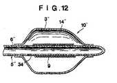
balloon catheter 10 having the dual tube structure. However, in the present embodiment, the ballooncatheter guide wire 15 is introduced into the lumen 6' at its proximal end and held so that its distal part does not break the balloon 3'. In this state, the air inside the balloon 3' is replaced by the contrast medium in the same way as in the preceding embodiment. The contrast medium are then sucked and discharged in a predetermined amount using the aforementioned in-deflator to cause the balloon 3' to be wrapped about the tubular member 5' to reduce the outside diameter of the balloon 3' so that the outside diameter of the portion introduced into the balloon catheter 10' is not more than 2.7 mm. - Referring to Fig. 12, illustrating a third embodiment of the present invention, a tubular member 5'' defining a sole lumen 6'' has a distal closed end. At the distal part of the tubular member 5'' is provided a balloon 3'' enclosing the distal part of the tubular member 5''. The lumen 6'' of the tubular member 5'' is in fluid communication with an expansion space 14'' of the balloon 3'' through an orifice or orifices formed in the tubular member 5''. The reinforcement 9 is provided at the distal part of the tubular member 5'' surrounded by the balloon 3'' and have turns thereof so wound that they be in intimate contact with each other. The operation of this balloon catheter is substantially same as those of the above-discribed balloon catheters.
- The coil spring reinforcement may alternatively be so wound that its turns are thick for example in intimate contact with each other in both end parts and thin or sparse in the intermediate part of the coil spring.
- The balloon catheter in this state is introduced into the
blood vessel 30, as it is guided by the ballooncatheter guide wire 15, until the balloon 3' reaches thestenosis site 32 in the same way as in the preceding embodiment. The contrast medium are then injected in a predetermined amount into the expansion space 14' of the balloon 3', with the aid of the pressure gauge-injector 24, for dilating the balloon 3' for pressuring and enlarging thestenosis 32. - When it is observed that the state of the blood stream is improved, the balloon catheter 10' may be removed from the inside of the blood vessel, as described hereinabove.
- In the present second embodiment, by providing the reinforcement 9 at the forward side of the tubular member 5', the tubular member can be reinforced against buckling.
- With the above described arrangement of the balloon catherter, the balloon portion of the balloon catherter may positively be proceeded to the target lesion, without breaking and collapsing of the tube portion enclosed in the balloon even at progress through an acute bend of the blood vessel.
Claims (8)
- A balloon catheter comprising a tubular body (5,5',5'') including at least one lumen, a foldable balloon (3,3',3'') provided at a predetermined distal portion on the outer surface of said tubular body (5,5',5'') so that the balloon communicates with at least one lumen (6,6'6'') in said tubular body, said balloon having a cylindrical section, and a coil spring reinforcement (9) formed of an X-ray opaque material extending only on a portion of said tubular body which is in register with the cylindrical section, characterized in that the lumen (6,6',6'') has a constant inner diameter in the portion surrounded by the balloon (3,3',3'') and said coil spring reinforcement is only wound on the outer surface of said tubular body surrounded by said balloon at said portion of the tubular body in register with said cylindrical section.
- The balloon catheter according to claim 1 wherein the outside diameter of a portion thereof introduced into the patient's body which is formed by said tubular body (5) and the folded balloon is not more than 2.7 mm.
- The balloon catheter according to claim 1 or 2 wherein said X-ray opague material is platinum, gold, tungsten or alloys thereof.
- The balloon catheter according to claim 1 or 2 wherein said X-ray opaque material is a silver-palladium alloy.
- The balloon catheter according to any one of the claims 1 to 4 wherein said reinforcement (9) is made of a wire.
- The balloon catheter according to claim 5 wherein the wire has a circular, rectangular or an elliptical cross-section.
- The balloon catheter according to claim 5 or 6 wherein said wire is so wound that its turns are in intimate contact with one another.
- The balloon catheter according to claim 5 or 6 wherein said wire is so wound that its turns are in intimate contact with each other in the both end parts and sparse in the intermediate part of the coil spring.
Applications Claiming Priority (2)
| Application Number | Priority Date | Filing Date | Title |
|---|---|---|---|
| JP62303930AJPH01145074A (en) | 1987-12-01 | 1987-12-01 | Balloon catheter |
| JP303930/87 | 1987-12-01 |
Publications (4)
| Publication Number | Publication Date |
|---|---|
| EP0318918A2 EP0318918A2 (en) | 1989-06-07 |
| EP0318918A3 EP0318918A3 (en) | 1989-12-13 |
| EP0318918B1 EP0318918B1 (en) | 1992-12-30 |
| EP0318918B2true EP0318918B2 (en) | 1996-11-27 |
Family
ID=17926989
Family Applications (1)
| Application Number | Title | Priority Date | Filing Date |
|---|---|---|---|
| EP88119881AExpired - LifetimeEP0318918B2 (en) | 1987-12-01 | 1988-11-29 | Balloon cathether |
Country Status (7)
| Country | Link |
|---|---|
| US (1) | US4994032A (en) |
| EP (1) | EP0318918B2 (en) |
| JP (1) | JPH01145074A (en) |
| AU (1) | AU603021B2 (en) |
| CA (1) | CA1325941C (en) |
| DE (1) | DE3877159T3 (en) |
| ES (1) | ES2036658T5 (en) |
Cited By (1)
| Publication number | Priority date | Publication date | Assignee | Title |
|---|---|---|---|---|
| WO2013067965A1 (en)* | 2011-11-10 | 2013-05-16 | 上海微创医疗器械(集团)有限公司 | Balloon dilation catheter |
Families Citing this family (150)
| Publication number | Priority date | Publication date | Assignee | Title |
|---|---|---|---|---|
| US5104399A (en) | 1986-12-10 | 1992-04-14 | Endovascular Technologies, Inc. | Artificial graft and implantation method |
| US5275622A (en)* | 1983-12-09 | 1994-01-04 | Harrison Medical Technologies, Inc. | Endovascular grafting apparatus, system and method and devices for use therewith |
| US7166125B1 (en) | 1988-03-09 | 2007-01-23 | Endovascular Technologies, Inc. | Intraluminal grafting system |
| US20040127969A1 (en)* | 1987-04-06 | 2004-07-01 | Lazarus Harrison M. | Artificial graft and implantation method |
| US5425711A (en)* | 1988-02-29 | 1995-06-20 | Scimed Life Systems, Inc. | Intravascular catheter with distal guide wire lumen and transition member |
| US6071273A (en)* | 1988-02-29 | 2000-06-06 | Scimed Life Systems, Inc. | Fixed wire dilatation balloon catheter |
| US6004291A (en)* | 1988-02-29 | 1999-12-21 | Scimed Life Systems, Inc. | Intravascular catheter with distal guide wire lumen and transition |
| US5156594A (en)* | 1990-08-28 | 1992-10-20 | Scimed Life Systems, Inc. | Balloon catheter with distal guide wire lumen |
| US5171297A (en)* | 1989-03-17 | 1992-12-15 | Angeion Corporation | Balloon catheter |
| US6344053B1 (en)* | 1993-12-22 | 2002-02-05 | Medtronic Ave, Inc. | Endovascular support device and method |
| US5263963A (en)* | 1989-09-08 | 1993-11-23 | Advanced Cardiovascular Systems, Inc. | Expandable cage catheter for repairing a damaged blood vessel |
| US5180368A (en)* | 1989-09-08 | 1993-01-19 | Advanced Cardiovascular Systems, Inc. | Rapidly exchangeable and expandable cage catheter for repairing damaged blood vessels |
| DK0420486T3 (en)* | 1989-09-25 | 1994-05-24 | Schneider Usa Inc | Thread-reinforced small diameter expansion catheter and coaxial tubular body |
| US5092839A (en)* | 1989-09-29 | 1992-03-03 | Kipperman Robert M | Coronary thrombectomy |
| JP2516453B2 (en)* | 1990-04-19 | 1996-07-24 | テルモ株式会社 | Caterer with extension body |
| US5176637A (en)* | 1990-04-19 | 1993-01-05 | Terumo Kabushiki Kaisha | Catheter equipped with a dilation element |
| US5395330A (en)* | 1990-06-13 | 1995-03-07 | Dlp, Inc. | Auto-inflating catheter cuff |
| US5217482A (en)* | 1990-08-28 | 1993-06-08 | Scimed Life Systems, Inc. | Balloon catheter with distal guide wire lumen |
| US5265622A (en)* | 1990-10-25 | 1993-11-30 | C. R. Bard, Inc. | Guidewire having radially expandable member and method for guiding and advancing a catheter using the same |
| US5445625A (en)* | 1991-01-23 | 1995-08-29 | Voda; Jan | Angioplasty guide catheter |
| EP0568624B1 (en)* | 1991-01-23 | 2001-10-04 | VODA, Jan | Guide catheter construction |
| US5183470A (en)* | 1991-03-04 | 1993-02-02 | International Medical, Inc. | Laparoscopic cholangiogram catheter and method of using same |
| US5584803A (en) | 1991-07-16 | 1996-12-17 | Heartport, Inc. | System for cardiac procedures |
| US5558644A (en)* | 1991-07-16 | 1996-09-24 | Heartport, Inc. | Retrograde delivery catheter and method for inducing cardioplegic arrest |
| US5769812A (en) | 1991-07-16 | 1998-06-23 | Heartport, Inc. | System for cardiac procedures |
| US6482171B1 (en) | 1991-07-16 | 2002-11-19 | Heartport, Inc. | Multi-lumen catheter |
| EP0600940B1 (en)* | 1991-07-24 | 1999-02-24 | Advanced Cardiovascular Systems, Inc. | Low profile perfusion-type dilatation catheter |
| US5171305A (en)* | 1991-10-17 | 1992-12-15 | Imagyn Medical, Inc. | Linear eversion catheter with reinforced inner body extension |
| US5571087A (en)* | 1992-02-10 | 1996-11-05 | Scimed Life Systems, Inc. | Intravascular catheter with distal tip guide wire lumen |
| US5649909A (en)* | 1992-04-06 | 1997-07-22 | Scimed Life Systems, Inc. | Variable stiffness multi-lumen catheter |
| US5306263A (en) | 1992-05-01 | 1994-04-26 | Jan Voda | Catheter |
| WO1994004216A1 (en) | 1992-08-25 | 1994-03-03 | Bard Connaught | Dilatation catheter with stiffening wire |
| US5500180A (en)* | 1992-09-30 | 1996-03-19 | C. R. Bard, Inc. | Method of making a distensible dilatation balloon using a block copolymer |
| US5304198A (en)* | 1992-11-13 | 1994-04-19 | Target Therapeutics | Single-lumen balloon catheter having a directional valve |
| US6096055A (en)* | 1992-11-13 | 2000-08-01 | Target Therapuetics, Inc. | Single-lumen balloon catheter having a directional valve |
| US5683410A (en)* | 1993-11-04 | 1997-11-04 | Target Therapeutics, Inc. | Single-lumen balloon catheter having a directional valve |
| US5304199A (en)* | 1993-01-04 | 1994-04-19 | Gene E. Myers Enterprises, Inc. | Apparatus for arterial total occlusion plaque separation |
| US5382234A (en)* | 1993-04-08 | 1995-01-17 | Scimed Life Systems, Inc. | Over-the-wire balloon catheter |
| US5338298A (en)* | 1993-06-04 | 1994-08-16 | C. R. Bard, Inc. | Double-tapered balloon |
| US6659977B2 (en)* | 1993-10-27 | 2003-12-09 | Schneider (Europe) A.G. | Multilayer interventional catheter |
| DE69326551T2 (en)* | 1993-10-27 | 2000-03-02 | Schneider (Europe) Gmbh, Buelach | Interventional catheter |
| US5961765A (en)* | 1994-09-20 | 1999-10-05 | Schneider (Europe) A. G. | Method of making a catheter |
| US5460608A (en)* | 1994-01-25 | 1995-10-24 | Scimed Life Systems, Inc. | Kink free catheter |
| US6051020A (en)* | 1994-02-09 | 2000-04-18 | Boston Scientific Technology, Inc. | Bifurcated endoluminal prosthesis |
| US6165213A (en)* | 1994-02-09 | 2000-12-26 | Boston Scientific Technology, Inc. | System and method for assembling an endoluminal prosthesis |
| US5609627A (en)* | 1994-02-09 | 1997-03-11 | Boston Scientific Technology, Inc. | Method for delivering a bifurcated endoluminal prosthesis |
| DE69527946T2 (en)* | 1994-03-01 | 2003-03-06 | Boston Scientific Corp., Natick | ASYMMETRIC DILATATION BALLOON |
| US5478309A (en) | 1994-05-27 | 1995-12-26 | William P. Sweezer, Jr. | Catheter system and method for providing cardiopulmonary bypass pump support during heart surgery |
| US5658264A (en)* | 1994-11-10 | 1997-08-19 | Target Therapeutics, Inc. | High performance spiral-wound catheter |
| CA2163708C (en)* | 1994-12-07 | 2007-08-07 | Robert E. Fischell | Integrated dual-function catheter system for balloon angioplasty and stent delivery |
| EP0828525B1 (en) | 1995-05-24 | 2004-07-28 | Schneider (Usa) Inc. | Dilatation balloons containing polyesteretheramide copolymer |
| US6814748B1 (en) | 1995-06-07 | 2004-11-09 | Endovascular Technologies, Inc. | Intraluminal grafting system |
| US6010530A (en)* | 1995-06-07 | 2000-01-04 | Boston Scientific Technology, Inc. | Self-expanding endoluminal prosthesis |
| US5776115A (en)* | 1996-01-17 | 1998-07-07 | Becton Dickinson And Company | Catheter having a gear-shaped lumen to avert the elimination of fluid flow therein |
| ATE248621T1 (en)* | 1996-01-19 | 2003-09-15 | Scimed Life Systems Inc | CATHETER WITH AN INCREASING RADIUS CURVE |
| ATE327797T1 (en) | 1996-04-26 | 2006-06-15 | Schneider Europ Gmbh | INTERVENTION CATHETER |
| US6042578A (en)* | 1996-05-13 | 2000-03-28 | Schneider (Usa) Inc. | Catheter reinforcing braids |
| US6077295A (en) | 1996-07-15 | 2000-06-20 | Advanced Cardiovascular Systems, Inc. | Self-expanding stent delivery system |
| US7749585B2 (en)* | 1996-10-08 | 2010-07-06 | Alan Zamore | Reduced profile medical balloon element |
| IT1289453B1 (en)* | 1996-12-16 | 1998-10-15 | Sis Ter Spa | GASTROSTOMIC TUBE DEVICE FOR ENTERAL NUTRITION |
| US6033379A (en)* | 1997-01-08 | 2000-03-07 | Medtronic, Inc. | Balloon catheter |
| US6379334B1 (en)* | 1997-02-10 | 2002-04-30 | Essex Technology, Inc. | Rotate advance catheterization system |
| US5755687A (en) | 1997-04-01 | 1998-05-26 | Heartport, Inc. | Methods and devices for occluding a patient's ascending aorta |
| US6165166A (en)* | 1997-04-25 | 2000-12-26 | Schneider (Usa) Inc. | Trilayer, extruded medical tubing and medical devices incorporating such tubing |
| DE69828429T2 (en)* | 1997-10-08 | 2005-12-08 | Kaneka Corp. | BALLOON CATHETER AND MANUFACTURING METHOD THEREFOR |
| US6048338A (en) | 1997-10-15 | 2000-04-11 | Scimed Life Systems, Inc. | Catheter with spiral cut transition member |
| US5989218A (en)* | 1997-11-18 | 1999-11-23 | Advanced Cardiovascular Systems, Inc. | Perfusion catheter with coil supported inner tubular member |
| US6159178A (en) | 1998-01-23 | 2000-12-12 | Heartport, Inc. | Methods and devices for occluding the ascending aorta and maintaining circulation of oxygenated blood in the patient when the patient's heart is arrested |
| JPH11342208A (en)* | 1998-06-02 | 1999-12-14 | Buaayu:Kk | Balloon catheter |
| US20020007145A1 (en)* | 1998-10-23 | 2002-01-17 | Timothy Stivland | Catheter having improved bonding region |
| US6102890A (en)* | 1998-10-23 | 2000-08-15 | Scimed Life Systems, Inc. | Catheter having improved proximal shaft design |
| DE69938790D1 (en) | 1998-12-09 | 2008-07-03 | Boston Scient Scimed Inc | CATHETER WITH IMPROVED CONTROL OF FLEXIBILITY |
| US6514228B1 (en) | 1999-03-05 | 2003-02-04 | Scimed Life Systems, Inc. | Balloon catheter having high flow tip |
| US6648854B1 (en) | 1999-05-14 | 2003-11-18 | Scimed Life Systems, Inc. | Single lumen balloon-tipped micro catheter with reinforced shaft |
| JP2001058009A (en)* | 1999-06-18 | 2001-03-06 | Usami Nano Technology:Kk | Catheter and guide wire |
| US6193686B1 (en) | 1999-06-30 | 2001-02-27 | Advanced Cardiovascular Systems, Inc. | Catheter with enhanced flexibility |
| AU7720100A (en)* | 1999-09-27 | 2001-04-30 | Essex Technology, Inc. | Rotate-to-advance catheterization system |
| US6652568B1 (en) | 1999-12-22 | 2003-11-25 | Advanced Cardiovascular Systems, Inc. | Radiopaque balloon |
| US6595983B2 (en) | 2000-12-07 | 2003-07-22 | Jan K. Voda | Guide or diagnostic catheter for right coronary artery |
| US6623504B2 (en) | 2000-12-08 | 2003-09-23 | Scimed Life Systems, Inc. | Balloon catheter with radiopaque distal tip |
| US6802825B2 (en)* | 2001-07-03 | 2004-10-12 | Coopersurgical, Inc. | Access catheter apparatus for use in minimally invasive surgery and diagnostic procedures in the uterus and fallopian tubes |
| US6911017B2 (en)* | 2001-09-19 | 2005-06-28 | Advanced Cardiovascular Systems, Inc. | MRI visible catheter balloon |
| US7201763B2 (en)* | 2001-10-24 | 2007-04-10 | Boston Scientific Scimed, Inc. | Distal balloon waist material relief and method of manufacture |
| US20030187498A1 (en)* | 2002-03-28 | 2003-10-02 | Medtronic Ave, Inc. | Chamfered stent strut and method of making same |
| DE10220409B4 (en)* | 2002-05-08 | 2006-03-02 | Raumedic Ag | Use of a catheter tube |
| US7867218B1 (en) | 2004-02-24 | 2011-01-11 | Voda Heart Technology, Llc | Steerable catheter for right coronary artery |
| US20050215950A1 (en)* | 2004-03-26 | 2005-09-29 | Scimed Life Systems, Inc. | Balloon catheter with radiopaque portion |
| US7824390B2 (en) | 2004-04-16 | 2010-11-02 | Kyphon SÀRL | Spinal diagnostic methods and apparatus |
| US7452351B2 (en)* | 2004-04-16 | 2008-11-18 | Kyphon Sarl | Spinal diagnostic methods and apparatus |
| US7744574B2 (en)* | 2004-12-16 | 2010-06-29 | Boston Scientific Scimed, Inc. | Catheter tip to reduce wire lock |
| EP1861133B1 (en)* | 2005-02-28 | 2012-11-21 | Spirus Medical Inc. | Rotate-to-advance catheterization system |
| US7780650B2 (en)* | 2005-05-04 | 2010-08-24 | Spirus Medical, Inc. | Rotate-to-advance catheterization system |
| US8343040B2 (en)* | 2005-05-04 | 2013-01-01 | Olympus Endo Technology America Inc. | Rotate-to-advance catheterization system |
| US20090005645A1 (en)* | 2005-05-04 | 2009-01-01 | Frassica James J | Rotate-to- advance catheterization system |
| US8414477B2 (en)* | 2005-05-04 | 2013-04-09 | Olympus Endo Technology America Inc. | Rotate-to-advance catheterization system |
| US8235942B2 (en)* | 2005-05-04 | 2012-08-07 | Olympus Endo Technology America Inc. | Rotate-to-advance catheterization system |
| US8317678B2 (en) | 2005-05-04 | 2012-11-27 | Olympus Endo Technology America Inc. | Rotate-to-advance catheterization system |
| US20070043389A1 (en)* | 2005-08-05 | 2007-02-22 | Shintech, Llc | System for treating chronic total occlusion caused by lower extremity arterial disease |
| WO2007070544A2 (en)* | 2005-12-13 | 2007-06-21 | Cook Incorporated | Implantable medical device using palladium |
| US8574220B2 (en) | 2006-02-28 | 2013-11-05 | Olympus Endo Technology America Inc. | Rotate-to-advance catheterization system |
| US8435229B2 (en) | 2006-02-28 | 2013-05-07 | Olympus Endo Technology America Inc. | Rotate-to-advance catheterization system |
| US7785317B2 (en)* | 2006-03-29 | 2010-08-31 | Codman & Shurtleff, Inc. | Joined metal tubing and method of manufacture |
| US7896840B2 (en)* | 2007-04-05 | 2011-03-01 | Boston Scientific Scimed, Inc. | Catheter having internal mechanisms to encourage balloon re-folding |
| EP2144660A4 (en)* | 2007-04-09 | 2016-05-04 | Creative Surgical Llc | FRAME DEVICE |
| US8870755B2 (en) | 2007-05-18 | 2014-10-28 | Olympus Endo Technology America Inc. | Rotate-to-advance catheterization system |
| JP2011512956A (en)* | 2008-02-26 | 2011-04-28 | ボストン サイエンティフィック サイムド,インコーポレイテッド | Balloon catheter with a highly durable tip |
| US10702293B2 (en) | 2008-06-13 | 2020-07-07 | Shockwave Medical, Inc. | Two-stage method for treating calcified lesions within the wall of a blood vessel |
| WO2009152352A2 (en) | 2008-06-13 | 2009-12-17 | Aspen Medtech, Inc. | Shockwave balloon catheter system |
| US8216498B2 (en) | 2008-09-10 | 2012-07-10 | Boston Scientific Scimed, Inc. | Catheter having a coextruded fluoropolymer layer |
| US9044618B2 (en) | 2008-11-05 | 2015-06-02 | Shockwave Medical, Inc. | Shockwave valvuloplasty catheter system |
| US20100228337A1 (en)* | 2009-03-04 | 2010-09-09 | Abbott Laboratories Vascular Enterprises Limited | Mirror image stent and method of use |
| JP2010264024A (en)* | 2009-05-13 | 2010-11-25 | Hi-Lex Corporation | Blood sampling catheter |
| WO2010144483A1 (en) | 2009-06-08 | 2010-12-16 | Trireme Medical, Inc. | Side branch balloon |
| US10155099B2 (en) | 2009-09-21 | 2018-12-18 | Cook Regentec Llc | Method for infusing stem cells |
| US10058675B2 (en) | 2009-09-21 | 2018-08-28 | Cook Regentec Llc | Infusion catheter tip for biologics with reinforced external balloon valve |
| US8827952B2 (en)* | 2010-12-06 | 2014-09-09 | Boston Scientific Scimed, Inc. | Biasing mechanism for a balloon catheter |
| US8469989B2 (en) | 2010-12-15 | 2013-06-25 | Cook Medical Technologies Llc | Pushable coaxial balloon catheter |
| AU2012222114B2 (en) | 2011-02-25 | 2016-06-16 | Microvention, Inc. | Reinforced balloon catheter |
| US9119716B2 (en) | 2011-07-27 | 2015-09-01 | Edwards Lifesciences Corporation | Delivery systems for prosthetic heart valve |
| CN107281617A (en)* | 2012-03-09 | 2017-10-24 | 明讯科技有限公司 | Foley's tube with expandable axle |
| IN2014DN07123A (en) | 2012-03-09 | 2015-04-24 | Clearstream Tech Ltd | |
| US10500378B2 (en) | 2012-03-09 | 2019-12-10 | Clearstream Technologies Limited | Medical balloon including radiopaque insert for precisely identifying a working surface location |
| JP6220355B2 (en) | 2012-03-09 | 2017-10-25 | クリアストリーム・テクノロジーズ・リミテッド | Medical balloon with a radiopaque end portion for accurately identifying the location of the working surface |
| AU2013300176B2 (en) | 2012-08-06 | 2017-08-17 | Shockwave Medical, Inc. | Low profile electrodes for an angioplasty shock wave catheter |
| US9554815B2 (en) | 2012-08-08 | 2017-01-31 | Shockwave Medical, Inc. | Shockwave valvuloplasty with multiple balloons |
| US9522012B2 (en) | 2012-09-13 | 2016-12-20 | Shockwave Medical, Inc. | Shockwave catheter system with energy control |
| US9333000B2 (en) | 2012-09-13 | 2016-05-10 | Shockwave Medical, Inc. | Shockwave catheter system with energy control |
| KR20160105829A (en)* | 2013-12-31 | 2016-09-07 | 쿡 리젠틱, 엘엘씨 | Infusion catheter tip for biologics with reinforced external balloon valve |
| EP3202452B1 (en)* | 2014-09-30 | 2019-04-10 | Piolax Medical Devices, Inc. | Balloon catheter |
| WO2017087195A1 (en) | 2015-11-18 | 2017-05-26 | Shockwave Medical, Inc. | Shock wave electrodes |
| AU2017339980B2 (en) | 2016-10-06 | 2022-08-18 | Shockwave Medical, Inc. | Aortic leaflet repair using shock wave applicators |
| JP6804802B2 (en)* | 2016-11-15 | 2020-12-23 | 日本ライフライン株式会社 | Balloon catheter |
| US10966737B2 (en) | 2017-06-19 | 2021-04-06 | Shockwave Medical, Inc. | Device and method for generating forward directed shock waves |
| US10709462B2 (en) | 2017-11-17 | 2020-07-14 | Shockwave Medical, Inc. | Low profile electrodes for a shock wave catheter |
| US10575973B2 (en) | 2018-04-11 | 2020-03-03 | Abbott Cardiovascular Systems Inc. | Intravascular stent having high fatigue performance |
| FR3080774B1 (en)* | 2018-05-04 | 2022-07-15 | Univ Bordeaux | CATHETER, INFLATABLE BALLOON FOR CATHETHER |
| EP3809988B1 (en) | 2018-06-21 | 2023-06-07 | Shockwave Medical, Inc. | System for treating occlusions in body lumens |
| WO2021061523A1 (en) | 2019-09-24 | 2021-04-01 | Shockwave Medical, Inc. | System for treating thrombus in body lumens |
| WO2021061451A1 (en) | 2019-09-24 | 2021-04-01 | Shockwave Medical, Inc. | Lesion crossing shock wave catheter |
| EP4512350A3 (en) | 2019-09-24 | 2025-05-07 | Shockwave Medical, Inc. | Low profile electrodes for a shock wave catheter |
| US11992232B2 (en) | 2020-10-27 | 2024-05-28 | Shockwave Medical, Inc. | System for treating thrombus in body lumens |
| US12232755B2 (en) | 2020-12-11 | 2025-02-25 | Shockwave Medical, Inc. | Lesion crossing shock wave catheter |
| US12023098B2 (en) | 2021-10-05 | 2024-07-02 | Shockwave Medical, Inc. | Lesion crossing shock wave catheter |
| US12290268B2 (en) | 2023-03-31 | 2025-05-06 | Shockwave Medical, Inc. | Shockwave catheters for treating rhinosinusitis |
| US12035932B1 (en) | 2023-04-21 | 2024-07-16 | Shockwave Medical, Inc. | Intravascular lithotripsy catheter with slotted emitter bands |
| US12220141B2 (en) | 2023-06-29 | 2025-02-11 | Shockwave Medical, Inc. | Catheter system with independently controllable bubble and arc generation |
| US12426904B2 (en) | 2023-11-17 | 2025-09-30 | Shockwave Medical, Inc. | Intravascular lithotripsy catheter with oscillating impactor |
| US12402899B2 (en) | 2023-11-30 | 2025-09-02 | Shockwave Medical, Inc. | Systems, devices, and methods for generating shock waves in a forward direction |
| US12433620B2 (en) | 2024-02-23 | 2025-10-07 | Shockwave Medical, Inc. | Locus emitter shock wave catheter devices with increased longevity and higher sonic output |
| US12178458B1 (en) | 2024-05-16 | 2024-12-31 | Shockwave Medical, Inc. | Guidewireless shock wave catheters |
Family Cites Families (12)
| Publication number | Priority date | Publication date | Assignee | Title |
|---|---|---|---|---|
| GB933307A (en)* | 1959-01-02 | 1963-08-08 | British Oxygen Co Ltd | Catheters |
| US3302637A (en)* | 1965-06-03 | 1967-02-07 | Myron W Mazeilan | Radio-opaque marking strip for internal bleeding markers |
| US3885561A (en)* | 1971-12-15 | 1975-05-27 | Charles N Mazal Cami | Catheter |
| US4307722A (en)* | 1979-08-14 | 1981-12-29 | Evans Joseph M | Dilators for arterial dilation |
| US4571240A (en)* | 1983-08-12 | 1986-02-18 | Advanced Cardiovascular Systems, Inc. | Catheter having encapsulated tip marker |
| US4597755A (en)* | 1984-05-30 | 1986-07-01 | Advanced Cardiovascular Systems, Inc. | Large bore catheter having flexible tip construction |
| US4646719A (en)* | 1984-06-11 | 1987-03-03 | Aries Medical Incorporated | Intra-aortic balloon catheter having flexible torque transmitting tube |
| JPS62148671A (en)* | 1985-12-24 | 1987-07-02 | 住友ベークライト株式会社 | Foreign matter removing catheter |
| EP0249338A3 (en)* | 1986-06-12 | 1988-12-14 | C.R. Bard, Inc. | Retroperfusion catheter |
| US4839658A (en)* | 1986-07-28 | 1989-06-13 | Hughes Aircraft Company | Process for en route aircraft conflict alert determination and prediction |
| EP0255369A3 (en)* | 1986-08-01 | 1988-10-19 | Advanced Cardiovascular Systems, Inc. | Catheter tip marker |
| US4782834A (en)* | 1987-01-06 | 1988-11-08 | Advanced Cardiovascular Systems, Inc. | Dual lumen dilatation catheter and method of manufacturing the same |
- 1987
- 1987-12-01JPJP62303930Apatent/JPH01145074A/enactiveGranted
- 1988
- 1988-11-29USUS07/277,564patent/US4994032A/ennot_activeExpired - Lifetime
- 1988-11-29ESES88119881Tpatent/ES2036658T5/ennot_activeExpired - Lifetime
- 1988-11-29DEDE3877159Tpatent/DE3877159T3/ennot_activeExpired - Lifetime
- 1988-11-29EPEP88119881Apatent/EP0318918B2/ennot_activeExpired - Lifetime
- 1988-11-30AUAU26418/88Apatent/AU603021B2/ennot_activeExpired
- 1988-12-01CACA000584758Apatent/CA1325941C/ennot_activeExpired - Lifetime
Cited By (1)
| Publication number | Priority date | Publication date | Assignee | Title |
|---|---|---|---|---|
| WO2013067965A1 (en)* | 2011-11-10 | 2013-05-16 | 上海微创医疗器械(集团)有限公司 | Balloon dilation catheter |
Also Published As
| Publication number | Publication date |
|---|---|
| AU2641888A (en) | 1989-06-01 |
| AU603021B2 (en) | 1990-11-01 |
| ES2036658T3 (en) | 1993-06-01 |
| JPH01145074A (en) | 1989-06-07 |
| EP0318918B1 (en) | 1992-12-30 |
| DE3877159T2 (en) | 1993-04-29 |
| JPH0410830B2 (en) | 1992-02-26 |
| EP0318918A2 (en) | 1989-06-07 |
| ES2036658T5 (en) | 1997-01-16 |
| CA1325941C (en) | 1994-01-11 |
| DE3877159T3 (en) | 1997-04-10 |
| US4994032A (en) | 1991-02-19 |
| DE3877159D1 (en) | 1993-02-11 |
| EP0318918A3 (en) | 1989-12-13 |
Similar Documents
| Publication | Publication Date | Title |
|---|---|---|
| EP0318918B2 (en) | Balloon cathether | |
| US5059176A (en) | Vascular system steerable guidewire with inflatable balloon | |
| US4881547A (en) | Angioplasty dilitation balloon catheter | |
| EP0688576B2 (en) | Vascular catheter | |
| US5207229A (en) | Flexibility steerable guidewire with inflatable balloon | |
| US5876344A (en) | Modular imaging/treatment catheter assembly and method | |
| CA2228346C (en) | Guidewire having a distal tip that can change its shape within a vessel | |
| US4582181A (en) | Steerable dilatation catheter | |
| EP0823261B1 (en) | Guidewire having a distal tip that can change its shape within a vessel | |
| EP0652786B1 (en) | Dilatation catheter with injection lumen | |
| USRE33166E (en) | Steerable dilatation catheter | |
| CA1315632C (en) | Kissing balloon catheter | |
| EP0808192B1 (en) | Esophageal dilation balloon catheter containing flexible nitinol wire | |
| EP0750879B1 (en) | A medical appliance for pressure measurement in a blood vessel | |
| US20050261719A1 (en) | Catheter and method of its use | |
| JPH0318905B2 (en) | ||
| US7160266B2 (en) | Inflatable balloon catheter with purge mechanism and method | |
| EP0309754B1 (en) | Angioplasty dilitation balloon catheter | |
| EP0519515B1 (en) | Blood vessel dilator | |
| EP0442480A1 (en) | Balloon catheter for dilating a prostatic urethra | |
| US4705510A (en) | Nephrostomy catheter with formed tip | |
| CA1254475A (en) | Nephrostomy catheter with side connector | |
| US4645490A (en) | Nephrostomy catheter with formed tip | |
| CA2078201C (en) | Soft tip angioplasty balloon catheter | |
| JPH0354592B2 (en) |
Legal Events
| Date | Code | Title | Description |
|---|---|---|---|
| PUAI | Public reference made under article 153(3) epc to a published international application that has entered the european phase | Free format text:ORIGINAL CODE: 0009012 | |
| 17P | Request for examination filed | Effective date:19881129 | |
| AK | Designated contracting states | Kind code of ref document:A2 Designated state(s):BE DE ES FR GB IT NL SE | |
| PUAL | Search report despatched | Free format text:ORIGINAL CODE: 0009013 | |
| AK | Designated contracting states | Kind code of ref document:A3 Designated state(s):BE DE ES FR GB IT NL SE | |
| 17Q | First examination report despatched | Effective date:19910404 | |
| GRAA | (expected) grant | Free format text:ORIGINAL CODE: 0009210 | |
| AK | Designated contracting states | Kind code of ref document:B1 Designated state(s):BE DE ES FR GB IT NL SE | |
| PG25 | Lapsed in a contracting state [announced via postgrant information from national office to epo] | Ref country code:NL Effective date:19921230 Ref country code:BE Effective date:19921230 | |
| ET | Fr: translation filed | ||
| REF | Corresponds to: | Ref document number:3877159 Country of ref document:DE Date of ref document:19930211 | |
| ITF | It: translation for a ep patent filed | ||
| REG | Reference to a national code | Ref country code:ES Ref legal event code:FG2A Ref document number:2036658 Country of ref document:ES Kind code of ref document:T5 | |
| NLV1 | Nl: lapsed or annulled due to failure to fulfill the requirements of art. 29p and 29m of the patents act | ||
| PLBI | Opposition filed | Free format text:ORIGINAL CODE: 0009260 | |
| 26 | Opposition filed | Opponent name:SCIMED LIFE SYSTEMS, INC. Effective date:19930927 | |
| PGFP | Annual fee paid to national office [announced via postgrant information from national office to epo] | Ref country code:GB Payment date:19931119 Year of fee payment:6 | |
| PG25 | Lapsed in a contracting state [announced via postgrant information from national office to epo] | Ref country code:GB Effective date:19941129 | |
| EAL | Se: european patent in force in sweden | Ref document number:88119881.6 | |
| GBPC | Gb: european patent ceased through non-payment of renewal fee | Effective date:19941129 | |
| PLAW | Interlocutory decision in opposition | Free format text:ORIGINAL CODE: EPIDOS IDOP | |
| ITF | It: translation for a ep patent filed | ||
| PUAH | Patent maintained in amended form | Free format text:ORIGINAL CODE: 0009272 | |
| STAA | Information on the status of an ep patent application or granted ep patent | Free format text:STATUS: PATENT MAINTAINED AS AMENDED | |
| ET1 | Fr: translation filed ** revision of the translation of the patent or the claims | ||
| 27A | Patent maintained in amended form | Effective date:19961127 | |
| AK | Designated contracting states | Kind code of ref document:B2 Designated state(s):BE DE ES FR GB IT NL SE | |
| REG | Reference to a national code | Ref country code:ES Ref legal event code:DC2A Kind code of ref document:T5 Effective date:19961212 | |
| EN | Fr: translation not filed | ||
| EN | Fr: translation not filed | Free format text:BO 97/17 PAGES 249, LA MENTION DE LA NON REMISE DE CETTE TRADUCTION | |
| ET | Fr: translation filed | Free format text:BO 96/47 PAGES 251, LA MENTION DE LA REMISE DE CETTE TRADUCTION REVISEE | |
| ET3 | Fr: translation filed ** decision concerning opposition | ||
| PGFP | Annual fee paid to national office [announced via postgrant information from national office to epo] | Ref country code:ES Payment date:20071127 Year of fee payment:20 Ref country code:DE Payment date:20071122 Year of fee payment:20 | |
| PGFP | Annual fee paid to national office [announced via postgrant information from national office to epo] | Ref country code:IT Payment date:20071126 Year of fee payment:20 | |
| PGFP | Annual fee paid to national office [announced via postgrant information from national office to epo] | Ref country code:SE Payment date:20071106 Year of fee payment:20 | |
| PGFP | Annual fee paid to national office [announced via postgrant information from national office to epo] | Ref country code:FR Payment date:20071108 Year of fee payment:20 | |
| REG | Reference to a national code | Ref country code:ES Ref legal event code:FD2A Effective date:20081201 | |
| PG25 | Lapsed in a contracting state [announced via postgrant information from national office to epo] | Ref country code:ES Free format text:LAPSE BECAUSE OF EXPIRATION OF PROTECTION Effective date:20081201 |