EP0317596B1 - Locking device for gripping pliers of a telemanipulator - Google Patents
Locking device for gripping pliers of a telemanipulatorDownload PDFInfo
- Publication number
- EP0317596B1 EP0317596B1EP88904563AEP88904563AEP0317596B1EP 0317596 B1EP0317596 B1EP 0317596B1EP 88904563 AEP88904563 AEP 88904563AEP 88904563 AEP88904563 AEP 88904563AEP 0317596 B1EP0317596 B1EP 0317596B1
- Authority
- EP
- European Patent Office
- Prior art keywords
- ring
- pinions
- series
- ball
- slave arm
- Prior art date
- Legal status (The legal status is an assumption and is not a legal conclusion. Google has not performed a legal analysis and makes no representation as to the accuracy of the status listed.)
- Expired - Lifetime
Links
- 230000033001locomotionEffects0.000claimsabstractdescription52
- 238000006073displacement reactionMethods0.000claimsabstract3
- 230000000903blocking effectEffects0.000claimsdescription17
- 230000007246mechanismEffects0.000claimsdescription15
- 230000000694effectsEffects0.000claimsdescription6
- 230000003100immobilizing effectEffects0.000claimsdescription3
- 230000009471actionEffects0.000abstractdescription5
- 210000003127kneeAnatomy0.000description16
- 230000005540biological transmissionEffects0.000description7
- 210000000629knee jointAnatomy0.000description3
- 239000003638chemical reducing agentSubstances0.000description2
- 230000000295complement effectEffects0.000description2
- 230000004044responseEffects0.000description2
- 230000006835compressionEffects0.000description1
- 238000007906compressionMethods0.000description1
- 230000006872improvementEffects0.000description1
- 238000012423maintenanceMethods0.000description1
- 210000000056organAnatomy0.000description1
- 230000009467reductionEffects0.000description1
- 238000004804windingMethods0.000description1
Images

Classifications
- B—PERFORMING OPERATIONS; TRANSPORTING
- B25—HAND TOOLS; PORTABLE POWER-DRIVEN TOOLS; MANIPULATORS
- B25J—MANIPULATORS; CHAMBERS PROVIDED WITH MANIPULATION DEVICES
- B25J15/00—Gripping heads and other end effectors
- B25J15/04—Gripping heads and other end effectors with provision for the remote detachment or exchange of the head or parts thereof
- B—PERFORMING OPERATIONS; TRANSPORTING
- B25—HAND TOOLS; PORTABLE POWER-DRIVEN TOOLS; MANIPULATORS
- B25J—MANIPULATORS; CHAMBERS PROVIDED WITH MANIPULATION DEVICES
- B25J3/00—Manipulators of leader-follower type, i.e. both controlling unit and controlled unit perform corresponding spatial movements
- Y—GENERAL TAGGING OF NEW TECHNOLOGICAL DEVELOPMENTS; GENERAL TAGGING OF CROSS-SECTIONAL TECHNOLOGIES SPANNING OVER SEVERAL SECTIONS OF THE IPC; TECHNICAL SUBJECTS COVERED BY FORMER USPC CROSS-REFERENCE ART COLLECTIONS [XRACs] AND DIGESTS
- Y10—TECHNICAL SUBJECTS COVERED BY FORMER USPC
- Y10T—TECHNICAL SUBJECTS COVERED BY FORMER US CLASSIFICATION
- Y10T74/00—Machine element or mechanism
- Y10T74/19—Gearing
- Y10T74/19637—Gearing with brake means for gearing
Definitions
- the inventionrelates to an automatic locking device for the mechanisms controlling the various movements of a gripper supported by a knee lever detachably attached to the end of a remote manipulator slave arm, during disassembly of the knee lever.
- this devicealso ensures the automatic locking of the aforementioned mechanisms during the disassembly of the gripper, when the latter is also removable.
- remote manipulatorsare devices allowing certain handling operations to be carried out inside confinement cells. These devices include, outside the cell, a master arm and a control handle mounted by a toggle at the end of the master arm.
- the part of the device located inside the cellconsists of a slave arm ending in a toggle on which is attached a gripper.
- These two parts of the manipulatorcan be connected either mechanically or electrically to each other, so that the slave arm and the gripper it supports reproduce almost identically the movements made on the master arm and on its control handle by the operator.
- the master and slave armscan be either articulated or telescopic (see for example EP-A-0 104 118).
- control handleas well as the gripper have two degrees of freedom to which is added the clamping movement of the gripper.
- degrees of freedomcorrespond to a possibility of pivoting of the handle and the clamp around an axis orthogonal to the axis of the arm. which supports them and a pivoting movement of the handle and the clamp around their own axis.
- the assembly formed by the gripper and by the toggle which supports itis generally detachably fixed to the end of the slave arm.
- the motors controlling the capstans for driving the tapes housed in the slave armare actuated, which has the effect to wrap or unroll the ribbons over a certain length.
- the ribbonsthen occupy a different position from that which they occupied before the removal of these organs. Since the ribbons housed in the slave arm most often have a limited additional stroke compared to the stroke which they should normally have to ensure the control of the movements of the clamp, it may then happen that one of the ribbons reach the end of their travel before the mechanical stop existing for this purpose on the clamp or on the knee lever comes into action.
- the subject of the inventionis precisely a device making it possible to remedy this drawback by ensuring an automatic locking of the mechanisms controlling the movements of the clamp, as soon as the toggle is disconnected.
- an automatic locking devicefor mechanisms controlling different movements of a gripper supported by a toggle removably attached to the end of a remote manipulator slave arm, during '' disassembly of the toggle joint, these mechanisms comprising a first series of pinions housed in the end of the slave arm and a second series of pinions mounted in the knee joint so as to be meshed with the pinions of the first series when the knee joint is attached at the end of the slave arm, this device being characterized in that it comprises movable locking members housed in the end of the slave arm, elastic means tending to apply these locking members against the pinions of the first series, and at least one stop integral with the blocking members to release the latter from the gables of the first series, so us the effect of the abutment of this stop against a vis-à-vis surface formed on the toggle joint, when the latter is fixed to the end of the slave arm.
- the automatic locking devicecomprises two series of blocking members, a blocking member of each series being applied against opposite sides of the teeth of each pinion of the first series of sprockets, under the effect of elastic means, to prevent any rotation of these sprockets when the toggle is removed.
- the locking members of each seriescan in particular be fixed on a common axis, a stop being fixed on each of said axes.
- the axes carrying the locking members of each seriesare arranged approximately on either side of the pinions of the first series of pinions, the locking members having the form of pawls oriented towards these pinions and applied against the latter by at least one tension spring interposed between the two series of locking members and forming said elastic means.
- control mechanisms of the aforementioned movementsfurther comprise a rotating clamp tightening control shaft, housed in a non-rotating tubular part of the toggle joint and of which a part projecting out of this part is provided with grooves, said part provided with grooves being received in a grooved hole formed in a clamp tightening control part when the latter is fixed to the toggle joint.
- the locking devicethen further comprises a ring interposed between the tubular part and the rotating shaft, means for immobilizing the rotating ring in the tubular part and for allowing limited movement of the ring along an axis common to the shaft.
- the ringhas an oblong hole oriented parallel to said axis, in which is received a key immobilizing the ring in rotation in the tubular part and allowing its movement between said front and rear positions.
- the ringcomprises a grooved inner crown, this crown being meshed with the grooves when the ring is in its front position, while it is housed in an annular groove extending the grooves, when the ring is in its rear position.
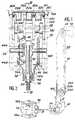
- FIG 1there is shown very schematically the front segment 10 of the slave arm of an articulated manipulator.
- This front segment 10is articulated by an elbow axis 12 on a rear segment 14, itself articulated by a shoulder axis on a support block mounted inside a cell (not shown).
- Removable fixing meansmake it possible to remotely mount and dismount a knee lever 16 at the free end of the slave arm 10.
- an articulated gripper 18is also detachably attached to the knee lever 18 by means which can be actuated remotely, which will be described later.
- removable fixing means provided between the slave arm 10 and the toggle 16 and between the toggle 16 and the clamp 18are not part of the invention and can be produced in any manner known to the mechanic .
- the inventionis not limited to the case where the gripper 18 is fixed on the toggle 16 in a removable manner but also applies to the case where such a disassembly is not possible.
- the knee lever 16makes it possible to pivot the gripper 18 around an axis orthogonal to the longitudinal axis of the arm 10 (arrow F1 in FIG. 1) and to rotate the gripper 18 around its own axis (arrow F2 in Figure 1). These two movements are mechanically limited by stops provided on the toggle joint 16.
- the gripper 18has a clamping movement (arrow F3 in Figure 1) which is mechanically limited by stops located in the clamp itself.
- the transmission inside the slave arm 10 of the control signals of each of the three movements F1, F2 and F3is carried out by means of ribbons 20 the ends of which lie at the interior of the support block are fixed on capstans (not shown) controlled by motors sensitive to signals from the master arm.
- each of the ribbons 20is wound on a pulley. More specifically, when three movements are transmitted to the clamp, three pairs of ribbons 20 are housed inside the slave arm, each of these pairs of ribbons ensuring the transmission of one of the movements.
- Each pair of ribbons 20is wound at the upper end of the slave arm on a double pulley 22a, 22b, and 22c, respectively. More specifically, the ends of two ribbons 20 of the same pair are fixed on the two pulleys of one of the double pulleys and are wound in opposite directions on these pulleys in order to transmit the corresponding movement in the two opposite directions.
- the three pulleys 22a, 22b and 22care mounted so as to be able to rotate freely on an axis 24 passing through the body 10a of the arm 10 perpendicular to its axis.
- Each of the pulleys 22a, 22b and 22cis secured a pinion 26a, 26b and 26c respectively.
- these pinionsall have the same diameter.
- the toggle joint 16comprises a housing 16a in which is fixed a pin 28 arranged parallel to the axis 24 when the toggle joint is fixed to the end of the slave arm.
- the axis 28rotatably supports three identical pinions 30a, 30b and 30c which are meshed respectively on the pinions 26a, 26b and 26c when the toggle is fixed on the arm.
- Each of the pinions 30a, 30b and 30cis integral with a second pinion 32a, 32b and 32c.
- the housing 16a of the toggle jointalso rotatably supports a second axis 34 disposed parallel to the axis 28. On this axis 34 are also rotatably received three pinions 36a, 36b and 36c which are meshed on the pinions 32a, 32b and 32c.
- a tubular part 38is fixed to the center of the axis 34, so that its axis is perpendicular to this axis 34.
- This tubular part 38projects by a slot in an arc 16b formed in the housing 16a of the toggle joint and it rotatably supports a shaft 40.
- the shaft 40supports a bevel gear 42 which is meshed with a bevel gear 44b secured to the gear 36b.
- the pinions 36a and 36care identical and arranged symmetrically on either side of the axis common to the shaft 40 and to the tubular part 38.
- these pinionsare respectively secured to a conical pinion 44a and a bevel gear 44c, these two bevel gears being identical and facing each other.
- the bevel gears 44a and 44care meshed on a bevel gear 46 secured to a tubular end piece 48 rotatably mounted on the tubular part 38.
- the rotating shaft 40, the tubular part 38 and the tubular end piece 48are arranged coaxially and all three comprise a part projecting from the housing 16a of the toggle joint by the opening in an arc of a circle 16b.
- the rotating shaft 40comprises outside of the housing 16a a part provided with grooves 50, this part being located projecting relative to the ends of the part 38 and the end piece 48.
- the clamp 18comprises a body of which only a tubular part 18a which covers the tubular end piece 48 of the toggle joint is shown in FIG. 3. Inside this tubular part 18a and set back relative to the end of this part, the body of the gripper rotatably supports a ring-shaped part 52, used to control the clamping of the gripper. This part 52 is crossed by a bore in which are formed grooves 56 complementary to the grooves 50 formed at the end of the rotating shaft 40.
- the tubular part 18a of the clamp bodycomes to cap the end piece 48 of the knee brace, the grooves 50 are engaged with the grooves 56.
- the part 52At its end located inside the clamp body, the part 52 is provided with an inclined toothing 58 cooperating in known manner with a pinion system controlling the bringing together of the jaws 18b (FIG. 1) of the clamp, when gripping movement F3 is necessary.
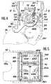
- this riskis completely eliminated thanks to a device making it possible to automatically lock the pinions 26a, 26b and 26c mounted at the end of the slave arm 10 when the toggle switch 16 is disconnected.
- this devicecomprises two series of three blocking members, the blocking members of each series being designated respectively by the references 60a, 60b and 60c and by the references 62a, 62b and 62c .
- Each of these locking membershas approximately the shape of a pawl.
- the three blocking members 60a, 60b and 60care fixed on a common axis 64 pivotally mounted inside the housing 10a, parallel to the axis 24.
- the three blocking members 62a, 62b and 62care also fixed on a common axis 66 mounted in the housing 10a, parallel to the axis 24 carrying the pulleys 22a, 22b and 22c and the pinions which are integral with them.
- the axes 64 and 66are located in the same plane perpendicular to the longitudinal axis of the slave arm and slightly offset towards the inside of this arm relative to the axis 24.
- these axes 64 and 66are arranged symmetrically with respect to a plane containing both the longitudinal axis of the slave arm and the axis 22.
- the locking members 60a, 60b and 60c on the one hand and the locking members 62a, 62b and 62c on the other handare placed opposite the pinions 26a, 26b and 26c respectively.
- the length of these locking membersis such that their end can come to bear on one of the sides of one of the teeth of the corresponding pinion. More specifically, the members 60a, 60b and 60c can come to bear on a side of one of the teeth of the corresponding pinion to prevent rotation in a first direction, while the members 62a, 62b and 62c can come to bear on an opposite flank of another tooth of this pinion, to prevent reverse rotation.
- the other two blocking members of the same seriesalso block the rotation in this same direction of the pinions. that match them.
- An unlocking finger 68, 70is secured to each of the axes 64 and 66 respectively.
- the two unlocking fingers 68 and 70are placed opposite one another and connected together by a tension spring 72 whose axis is offset towards the inside of the slave arm relative to the plane containing the axes 64 and 66, so that it tends to tilt the locking members towards the pinions 26a, 26b and 26c.
- each of the unlocking fingers 68 and 70carries a stop 73 and 74 respectively.
- these stops 73 and 74are supported on a projecting surface 76 formed on the housing 16a of the toggle joint, so that that all the locking members 60a, 60b, 60c, 62a, 62b and 62c are kept apart from the pinions 26a, 26b and 26c despite the action of the spring 72.
- the device shown in the figuresalso makes it possible to lock the rotating shaft 40 controlling the clamping movement of the clamp when the latter is dismantled .
- a ring 78is interposed for this purpose between the rotating shaft 40 and the tubular clamp 38, at the end of the latter.
- This ring 78is pierced with an oblong hole 80 oriented parallel to its axis and into which a key 82 penetrates.
- This keyimmobilizes the ring 78 in rotation inside the tubular part 38, while allowing the ring to move parallel to its axis between a rear position shown in solid lines on the left half of Figure 3 and a front position shown in solid lines on the right half of this same figure.
- a compression spring 84is housed in a space formed between the ring 78 and the shaft 40. This spring is supported by one of its ends on a flange 86 formed on the shaft 40 and by its opposite end on a shoulder formed on the ring 78. The spring 84 thus tends to move the ring 78 towards its front position.
- the ring 78comprises a part which projects beyond the end of the tubular part 38, this projecting part forming an inner ring provided with grooves 88 complementary to the grooves 50.
- the grooves 88are engaged on the grooves 50.
- the grooves 88are opposite an annular groove 90 formed on the shaft 40, in the extension of the grooves 50.
- the first of these mechanismscomprises two hooks 92 fixed on the body 10a of the slave arm, so as to come partially surround a cylindrical rod 94 mounted parallel to the axes 28 and 34 inside the housing 16a knee brace.
- the locking of the linkis carried out automatically by a rocking lever 96 mounted to pivot about an axis 98 parallel to the rod 94 in the housing of the toggle joint.
- a spring 100acts on this lever 96, so as to engage a hook-shaped end 102 of this lever in a hole formed for this purpose in the body 10a of the slave arm. Unlocking is easily obtained by exerting a force on the end of the lever 96 opposite the hook-shaped end 102, to release the latter from the hole formed in the body 10a.
- the hook 92can then be released from the rod 94.
- FIGS. 3, 4 and 6A mechanism for detachably fixing the clamp 18 on the toggle joint 16 is shown in FIGS. 3, 4 and 6.
- This mechanismessentially comprises two jaws 104 articulated on the tubular part 18a of the clamp body by two axes 106 parallel to the axis of this cylindrical part.
- These jaws 104are housed in suitable slots formed in the tubular part 18a, so that they can protrude inside the latter and come to fit in diametrically opposite straight grooves 108 formed on the external surface. of the tubular end piece 48.
- a torsion spring 110 carried by the tubular part 18a of the clamp bodyacts simultaneously on the two jaws 104 to rotate them around their axes 106 in the direction tending to cause these jaws to penetrate into the grooves 108.
- the jaws 104automatically fit into the grooves 108, thus securing the gripper body of the end piece 48 in rotation and in translation.
- the jaws 104are pivoted in the opposite direction by means of a tool 112 of which only a part is shown in the figure.
- This tool 112comes into contact with parts of the jaws 104 protruding outside the cylindrical part 18a of the clamp body. The desired tilting of the jaws can thus be controlled using the tool.
- the inventionalso applies to the case of a telescopic manipulator, and whatever the number of ribbons used to control the movements of the clamp.
Landscapes
- Engineering & Computer Science (AREA)
- Robotics (AREA)
- Mechanical Engineering (AREA)
- Surgical Instruments (AREA)
- Manipulator (AREA)
Abstract
Description
Translated fromFrenchL'invention concerne un dispositif de verrouillage automatique des mécanismes commandant les différents mouvements d'une pince de préhension supportée par une genouillère fixée de façon démontable à l'extrémité d'un bras esclave de télémanipulateur, lors d'un démontage de la genouillère. De façon facultative, ce dispositif assure également le verrouillage automatique des mécanismes précités lors du démontage de la pince de préhension, lorsque celle-ci est également démontable.The invention relates to an automatic locking device for the mechanisms controlling the various movements of a gripper supported by a knee lever detachably attached to the end of a remote manipulator slave arm, during disassembly of the knee lever. Optionally, this device also ensures the automatic locking of the aforementioned mechanisms during the disassembly of the gripper, when the latter is also removable.
On sait que les télémanipulateurs sont des appareils permettant d'effectuer à distance certaines manutentions à l'intérieur de cellules de confinement. Ces appareils comprennent, à l'extérieur de la cellule, un bras maître et une poignée de commande montée par une genouillère à l'extrémité du bras maître. La partie de l'appareil située à l'intérieur de la cellule se compose d'un bras esclave terminé par une genouillère sur laquelle est fixée une pince de préhension. Ces deux parties du télémanipulateur peuvent être reliées soit mécaniquement, soit électriquement entre elles, afin que le bras esclave et la pince de préhension qu'il supporte reproduisent pratiquement à l'identique les mouvements effectués sur le bras maître et sur sa poignée de commande par l'opérateur. Selon le type de manutention à réaliser, les bras maître et esclave peuvent être soit articulés, soit télescopiques (voir par exemple EP-A-0 104 118).We know that remote manipulators are devices allowing certain handling operations to be carried out inside confinement cells. These devices include, outside the cell, a master arm and a control handle mounted by a toggle at the end of the master arm. The part of the device located inside the cell consists of a slave arm ending in a toggle on which is attached a gripper. These two parts of the manipulator can be connected either mechanically or electrically to each other, so that the slave arm and the gripper it supports reproduce almost identically the movements made on the master arm and on its control handle by the operator. Depending on the type of handling to be carried out, the master and slave arms can be either articulated or telescopic (see for example EP-
Généralement, la poignée de commande ainsi que la pince de préhension disposent de deux degrés de liberté auxquels s'ajoute le mouvement de serrage de la pince. Ces degrés de liberté correspondent à une possibilité de pivotement de la poignée et de la pince autour d'un axe orthogonal à l'axe du bras qui les supporte et à un mouvement de pivotement de la poignée et de la pince autour de leur axe propre.Generally, the control handle as well as the gripper have two degrees of freedom to which is added the clamping movement of the gripper. These degrees of freedom correspond to a possibility of pivoting of the handle and the clamp around an axis orthogonal to the axis of the arm. which supports them and a pivoting movement of the handle and the clamp around their own axis.
Pour transmettre ces différents mouvements le long des bras, on utilise fréquemment des rubans enroulés sur des poulies et dont les extrémités sont fixées sur des cabestans. Dans le cas où la transmission des mouvements entre les bras maître et esclave s'effectue électriquement, les cabestans situés à l'extrémité supérieure du bras esclave sont commandés par des moteurs dont l'actionnement intervient lorsque des signaux représentatifs d'un mouvement correspondant du bras maître sont reçus.To transmit these different movements along the arms, ribbons wound on pulleys are frequently used, the ends of which are fixed on capstans. In the case where the transmission of movements between the master and slave arms is carried out electrically, the capstans located at the upper end of the slave arm are controlled by motors, the actuation of which occurs when signals representative of a corresponding movement of the master arms are received.
Par ailleurs, pour faciliter la maintenance et pour permettre de réaliser à l'intérieur d'une même cellule des opérations de nature différente, l'ensemble formé par la pince de préhension et par la genouillère qui la supporte est généralement fixé de façon démontable à l'extrémité du bras esclave.Furthermore, to facilitate maintenance and to allow operations of a different nature to be carried out inside the same cell, the assembly formed by the gripper and by the toggle which supports it is generally detachably fixed to the end of the slave arm.
Si un actionnement inopiné de la poignée de commande par l'opérateur se produit alors que la pince de préhension et sa genouillère sont déconnectées, les moteurs commandant les cabestans d'entraînement des rubans logés dans le bras esclave sont actionnés, ce qui a pour effet d'enrouler ou de dérouler les rubans sur une certaine longueur. Lorsque la pince et la genouillère sont remises en place, les rubans occupent alors une position différente de celle qu'ils occupaient avant l'enlèvement de ces organes. Etant donné que les rubans logés dans le bras esclave disposent le plus souvent d'une course supplémentaire limitée par rapport à la course dont ils doivent normalement disposer pour assurer la commande des mouvements de la pince, il peut alors se trouver que l'un des rubans arrive en bout de course avant que la butée mécanique existant à cet effet sur la pince ou sur la genouillère n'entre en action.If an unexpected actuation of the control handle by the operator occurs while the gripper and its knee switch are disconnected, the motors controlling the capstans for driving the tapes housed in the slave arm are actuated, which has the effect to wrap or unroll the ribbons over a certain length. When the clamp and the knee brace are replaced, the ribbons then occupy a different position from that which they occupied before the removal of these organs. Since the ribbons housed in the slave arm most often have a limited additional stroke compared to the stroke which they should normally have to ensure the control of the movements of the clamp, it may then happen that one of the ribbons reach the end of their travel before the mechanical stop existing for this purpose on the clamp or on the knee lever comes into action.
Dans ces conditions, il arrive relativement fréquemment que les rubans de transmission de mouvements logés dans le bras esclave se cassent. Un tel incident est particulièrement gênant car il entraîne une immobilisation du télémanipulateur et une intervention longue et coûteuse.Under these conditions, it relatively frequently happens that the motion transmission tapes housed in the slave arm break. Such an incident is particularly troublesome because it leads to immobilization of the manipulator and a long and costly intervention.
Si le risque qui vient d'être expliqué est particulièrement grand lorsque la transmission des mouvements entre le bras maître et le bras esclave s'effectue électriquement, car les moteurs continuent alors à exercer leur action lorsque les rubans sont en bout de course, il existe également lorsque cette transmission de mouvements s'effectue mécaniquement, car la réaction de l'opérateur peut dans certains cas être trop tardive.If the risk which has just been explained is particularly great when the transmission of movements between the master arm and the slave arm takes place electrically, since the motors then continue to exert their action when the ribbons are at the end of their travel, there is also when this transmission of movements takes place mechanically, since the operator's reaction may in some cases be too late.
L'invention a précisément pour objet un dispositif permettant de remédier à cet inconvénient en assurant un verrouillage automatique des mécanismes commandant les mouvements de la pince, dès que la genouillère est déconnectée.The subject of the invention is precisely a device making it possible to remedy this drawback by ensuring an automatic locking of the mechanisms controlling the movements of the clamp, as soon as the toggle is disconnected.
De façon plus précise, il est proposé selon l'invention un dispositif de verrouillage automatique de mécanismes commandant différents mouvements d'une pince de préhension supportée par une genouillère fixée de façon démontable à l'extrémité d'un bras esclave de télémanipulateur, lors d'un démontage de la genouillère, ces mécanismes comprenant une première série de pignons logés dans l'extrémité du bras esclave et une deuxième série de pignons montés dans la genouillère de façon à être engrenés sur les pignons de la première série lorsque la genouillère est fixée à l'extrémité du bras esclave, ce dispositif étant caractérisé en ce qu'il comprend des organes de blocage mobiles logés dans l'extrémité du bras esclave, des moyens élastiques tendant à appliquer ces organes de blocage contre les pignons de la première série, et au moins une butée solidaire des organes de blocage pour dégager ces derniers des pignons de la première série, sous l'effet de la venue en appui de cette butée contre une surface en vis-à-vis formée sur la genouillère, lorsque cette dernière est fixée à l'extrémité du bras esclave.More specifically, there is proposed according to the invention an automatic locking device for mechanisms controlling different movements of a gripper supported by a toggle removably attached to the end of a remote manipulator slave arm, during '' disassembly of the toggle joint, these mechanisms comprising a first series of pinions housed in the end of the slave arm and a second series of pinions mounted in the knee joint so as to be meshed with the pinions of the first series when the knee joint is attached at the end of the slave arm, this device being characterized in that it comprises movable locking members housed in the end of the slave arm, elastic means tending to apply these locking members against the pinions of the first series, and at least one stop integral with the blocking members to release the latter from the gables of the first series, so us the effect of the abutment of this stop against a vis-à-vis surface formed on the toggle joint, when the latter is fixed to the end of the slave arm.
Grâce à un tel dispositif, il n'est plus possible par une manoeuvre inopinée de la poignée de commande d'entraîner les rubans de transmission de mouvements logés dans le bras esclave lorsque la pince et la genouillère qui la supportent sont déconnectées. Par conséquent, aucun décalage ne peut être créé entre ces rubans et les organes correspondants logés dans la genouillère et dans la pince, de sorte que l'arrivée en bout de course des rubans avant la venue en butée des organes mécaniques de la pince n'est plus possible. De ce fait, tout risque de cassure accidentelle des rubans due à une telle manoeuvre est supprimé.Thanks to such a device, it is no longer possible by an unexpected operation of the control handle to drive the motion transmission tapes housed in the slave arm. when the clamp and the toggle support are disconnected. Consequently, no offset can be created between these ribbons and the corresponding members housed in the toggle joint and in the clamp, so that the arrival at the end of the travel of the ribbons before the mechanical members of the clamp stop is no longer possible. Therefore, any risk of accidental breakage of the tapes due to such an operation is eliminated.
Selon un mode de réalisation préféré de l'invention, le dispositif de verrouillage automatique comprend deux séries d'organes de blocage, un organe de blocage de chaque série venant s'appliquer contre des flancs opposés des dents de chaque pignon de la première série de pignons, sous l'effet des moyens élastiques, pour interdire toute rotation de ces pignons lorsque la genouillère est démontée.According to a preferred embodiment of the invention, the automatic locking device comprises two series of blocking members, a blocking member of each series being applied against opposite sides of the teeth of each pinion of the first series of sprockets, under the effect of elastic means, to prevent any rotation of these sprockets when the toggle is removed.
Les organes de blocage de chaque série peuvent notamment être fixés sur un axe commun, une butée étant fixée sur chacun desdits axes.The locking members of each series can in particular be fixed on a common axis, a stop being fixed on each of said axes.
De préférence, les axes portant les organes de blocage de chaque série sont disposés approximativement de part et d'autre des pignons de la première série de pignons, les organes de blocage ayant la forme de cliquets orientés vers ces pignons et appliqués contre ces derniers par au moins un ressort de traction interposé entre les deux séries d'organes de blocage et formant lesdits moyens élastiques.Preferably, the axes carrying the locking members of each series are arranged approximately on either side of the pinions of the first series of pinions, the locking members having the form of pawls oriented towards these pinions and applied against the latter by at least one tension spring interposed between the two series of locking members and forming said elastic means.
Dans le cas particulier où la pince de préhension est elle-même fixée de façon démontable sur la genouillère, les butées mécaniques de fin de course concernant le mouvement de serrage de la pince sont supprimées lorsque celle-ci est démontée. Le problème précédent se trouve donc limité dans ce cas au risque de rupture du ruban commandant ce serrage, si la poignée est actionnée de façon intempestive lorsque la pince est démontée.In the particular case where the gripping pliers are themselves detachably fixed on the toggle joint, the mechanical end-of-travel stops relating to the clamping movement of the pliers are eliminated when the latter is dismantled. The previous problem is therefore limited in this case to the risk of rupture of the ribbon controlling this tightening, if the handle is actuated inadvertently when the clamp is removed.
Dans ce cas particulier et conformément à un perfectionnement de l'invention, les mécanismes de commande de mouvements précités comprennent de plus un arbre tournant de commande de serrage de la pince, logé dans une pièce tubulaire non tournante de la genouillère et dont une partie faisant saillie hors de cette pièce est pourvue de cannelures, ladite partie pourvue de cannelures étant reçue dans un trou cannelé formé dans une pièce de commande de serrage de la pince lorsque cette dernière est fixée sur la genouillère. Le dispositif de verrouillage comprend alors de plus une bague interposée entre la pièce tubulaire et l'arbre tournant, des moyens pour immobiliser la bague en rotation dans la pièce tubulaire et pour permettre un déplacement limité de la bague selon un axe commun à l'arbre tournant, à la pièce tubulaire et à la bague entre une position avant dans laquelle la bague est engrenée sur les cannelures de ladite partie et une position arrière dans laquelle la bague est dégagée desdites cannelures, des moyens élastiques tendant à déplacer la bague vers ladite position avant, et une surface d'appui formée sur la pièce de commande de serrage, cette surface d'appui maintenant ladite bague dans sa position arrière lorsque la pince est fixée sur la genouillère.In this particular case and in accordance with an improvement of the invention, the control mechanisms of the aforementioned movements further comprise a rotating clamp tightening control shaft, housed in a non-rotating tubular part of the toggle joint and of which a part projecting out of this part is provided with grooves, said part provided with grooves being received in a grooved hole formed in a clamp tightening control part when the latter is fixed to the toggle joint. The locking device then further comprises a ring interposed between the tubular part and the rotating shaft, means for immobilizing the rotating ring in the tubular part and for allowing limited movement of the ring along an axis common to the shaft. rotating, to the tubular part and to the ring between a front position in which the ring is engaged on the grooves of said part and a rear position in which the ring is released from said grooves, elastic means tending to move the ring towards said position front, and a bearing surface formed on the clamping control part, this bearing surface maintaining said ring in its rear position when the clamp is fixed on the toggle joint.
De préférence, la bague présente un trou oblong orienté parallèlement audit axe, dans lequel est reçue une clavette immobilisant la bague en rotation dans la pièce tubulaire et permettant son déplacement entre lesdites positions avant et arrière.Preferably, the ring has an oblong hole oriented parallel to said axis, in which is received a key immobilizing the ring in rotation in the tubular part and allowing its movement between said front and rear positions.
Dans un mode de réalisation particulier de l'invention, la bague comprend une couronne intérieure cannelée, cette couronne étant engrenée sur les cannnelures lorsque la bague est dans sa position avant, alors qu'elle est logée dans une gorge annulaire prolongeant les cannelures, lorsque la bague est dans sa position arrière.In a particular embodiment of the invention, the ring comprises a grooved inner crown, this crown being meshed with the grooves when the ring is in its front position, while it is housed in an annular groove extending the grooves, when the ring is in its rear position.
Un mode de réalisation préféré de l'invention va maintenant être décrit, à titre d'exemple nullement limitatif, en se référant aux dessins annexés dans lesquels:
- la figure 1 est une vue de côté représentant schématiquement le bras esclave d'un télémanipulateur, la genouillère démontable pouvant être fixée à l'extrémité de ce bras et la pince de préhension démontable pouvant être fixée sur cette genouillère,
- la figure 2 est une vue en coupe longitudinale selon la ligne II-II de la figure 1, représentant à plus grande échelle l'extrémité du bras esclave ainsi que la genouillère,
- la figure 3 est une vue en coupe longitudinale partielle représentant les parties attenantes de la pince de préhension et de la genouillère en cours de raccordement,
- la figure 4 est une vue en coupe selon la ligne IV-IV de la figure 2,
- la figure 5 est une vue en coupe selon la ligne V-V de la figure 4, et
- la figure 6 est une vue en coupe selon la ligne VI-VI de la figure 3.
- Figure 1 is a side view schematically showing the slave arm of a manipulator, the removable knee brace which can be fixed at the end of this arm and the removable gripper which can be fixed on this knee brace,
- FIG. 2 is a view in longitudinal section along the line II-II of FIG. 1, showing on a larger scale the end of the slave arm as well as the knee switch,
- FIG. 3 is a view in partial longitudinal section showing the adjoining parts of the gripper and the toggle joint during connection,
- FIG. 4 is a sectional view along the line IV-IV of FIG. 2,
- FIG. 5 is a sectional view along the line VV of FIG. 4, and
- Figure 6 is a sectional view along line VI-VI of Figure 3.
Sur la figure 1, on a représenté de façon très schématique le segment avant 10 du bras esclave d'un télémanipulateur articulé. Ce segment avant 10 est articulé par un axe de coude 12 sur un segment arrière 14, lui-même articulé par un axe d'épaule sur un bloc support monté à l'intérieur d'une cellule (non représentée).In Figure 1, there is shown very schematically the
Des moyens de fixation démontables permettent de monter et de démonter à distance une genouillère 16 à l'extrémité libre du bras esclave 10. Dans l'exemple de réalisation représenté, une pince de préhension articulée 18 est également fixée de façon démontable sur la genouillère 18 par des moyens pouvant être actionnés à distance, qui seront décrits ultérieurement.Removable fixing means make it possible to remotely mount and dismount a
Il est à noter que les moyens de fixation démontables prévus entre le bras esclave 10 et la genouillère 16 et entre la genouillère 16 et la pince 18 ne font pas partie de l'invention et peuvent être réalisés d'une manière quelconque, connue du mécanicien.It should be noted that the removable fixing means provided between the
Il est également noté que l'invention n'est pas limitée au cas où la pince de préhension 18 est fixée sur la genouillère 16 de façon démontable mais s'applique également au cas où un tel démontage n'est pas possible.It is also noted that the invention is not limited to the case where the
Comme on le verra plus en détail ultérieurement, la genouillère 16 permet de faire pivoter la pince de préhension 18 autour d'un axe orthogonal à l'axe longitudinal du bras 10 (flèche F₁ sur la figure 1) et de faire tourner la pince 18 autour de son axe propre (flèche F₂ sur la figure 1). Ces deux mouvements sont limites mécaniquement par des butées prévues sur la genouillère 16.As will be seen in more detail later, the
Par ailleurs, la pince de préhension 18 est dotée d'un mouvement de serrage (flèche F₃ sur la figure 1) qui est limité mécaniquement par des butées situées dans la pince elle-même.Furthermore, the
Comme on l'a illustré très schématiquement sur la figure 1, la transmission à l'intérieur du bras esclave 10 des signaux de commande de chacun des trois mouvements F₁, F₂ et F₃ s'effectue au moyen de rubans 20 dont les extrémités situées à l'intérieur du bloc support sont fixées sur des cabestans (non représentés) commandés par des moteurs sensibles à des signaux en provenance du bras maître.As illustrated very diagrammatically in FIG. 1, the transmission inside the
A l'extrémité libre du bras esclave 10, chacun des rubans 20 s'enroule sur une poulie. Plus précisément, lorsque trois mouvements sont transmis à la pince, trois paires de rubans 20 sont logées à l'intérieur du bras esclave, chacune de ces paires de rubans assurant la transmission de l'un des mouvements. Chaque paire de rubans 20 s'enroule à l'extrémité supérieure du bras esclave sur une poulie double 22a, 22b, et 22c, respectivement. Plus précisément, les extrémités de deux rubans 20 d'une même paire sont fixées sur les deux poulies de l'une des poulies doubles et s'enroulent en sens inverse sur ces poulies afin de transmettre le mouvement correspondant dans les deux sens opposés.At the free end of the
Comme l'illustre plus en détail la figure 2, les trois poulies 22a, 22b et 22c sont montées de façon à pouvoir tourner librement sur un axe 24 traversant le corps 10a du bras 10 perpendiculairement à son axe.As illustrated in more detail in FIG. 2, the three
Chacune des poulies 22a, 22b et 22c est solidarisée d'un pignon 26a, 26b et 26c respectivement. Dans l'exemple représenté, ces pignons ont tous le même diamètre.Each of the
Les moyens permettant de transmettre à la pince les mouvements parvenant aux poulies 22a à 22c vont maintenant être décrits en se référant aux figures 2 et 3.The means enabling the movements arriving at the pulleys 22a to 22c to be transmitted to the clamp will now be described with reference to FIGS. 2 and 3.
Comme l'illustre la figure 2, la genouillère 16 comprend un boîtier 16a dans lequel est fixé un axe 28 disposé parallèlement à l'axe 24 lorsque la genouillère est fixée à l'extrémité du bras esclave. L'axe 28 supporte de façon tournante trois pignons identiques 30a, 30b et 30c qui sont engrenés respectivement sur les pignons 26a, 26b et 26c lorsque la genouillère est fixée sur le bras.As illustrated in FIG. 2, the toggle joint 16 comprises a housing 16a in which is fixed a
Chacun des pignons 30a, 30b et 30c est solidaire d'un deuxième pignon 32a, 32b et 32c.Each of the
Le boîtier 16a de la genouillère supporte également de façon tournante un deuxième axe 34 disposé parallèlement à l'axe 28. Sur cet axe 34 sont également reçus de façon tournante trois pignons 36a, 36b et 36c qui sont engrenés sur les pignons 32a, 32b et 32c.The housing 16a of the toggle joint also rotatably supports a
Une pièce tubulaire 38 est fixée au centre de l'axe 34, de telle sorte que son axe soit perpendiculaire à cet axe 34. Cette pièce tubulaire 38 fait saillie par une fente en arc de cercle 16b formée dans le boîtier 16a de la genouillère et elle supporte de façon tournante un arbre 40.A
A son extrémité située à l'intérieur du boîtier de la genouillère, l'arbre 40 supporte un pignon conique 42 qui est engrené sur un pignon conique 44b solidaire du pignon 36b.At its end located inside the toggle joint housing, the
Par ailleurs, les pignons 36a et 36c sont identiques et disposés symétriquement de part et d'autre de l'axe commun à l'arbre 40 et à la pièce tubulaire 38. De plus, ces pignons sont solidaires respectivement d'un pignon conique 44a et d'un pignon conique 44c, ces deux pignons coniques étant identiques et se faisant face. Les pignons coniques 44a et 44c sont engrenés sur un pignon conique 46 solidaire d'un embout tubulaire 48 monté de façon tournante sur la pièce tubulaire 38.Furthermore, the pinions 36a and 36c are identical and arranged symmetrically on either side of the axis common to the
L'arbre tournant 40, la pièce tubulaire 38 et l'embout tubulaire 48 sont disposés coaxialement et comprennent tous trois une partie faisant saillie hors du boîtier 16a de la genouillère par l'ouverture en arc de cercle 16b.The rotating
De plus, l'arbre tournant 40 comprend à l'extérieur du boîtier 16a une partie pourvue de cannelures 50, cette partie étant située en saillie par rapport aux extrémités de la pièce 38 et de l'embout 48.In addition, the rotating
Comme l'illustre en particulier la figure 3, ces différentes parties en saillie de l'arbre 40, de la pièce 38 et de l'embout 48 permettent de fixer de façon démontable la pince de préhension 18 sur la genouillère 16.As illustrated in particular in FIG. 3, these different projecting parts of the
A cet effet, la pince 18 comprend un corps dont seule une partie tubulaire 18a venant coiffer l'embout tubulaire 48 de la genouillère est représentée sur la figure 3. A l'intérieur de cette partie tubulaire 18a et en retrait par rapport à l'extrémité de cette partie, le corps de la pince de préhension supporte de façon tournante une pièce en forme de bague 52, servant à commander le serrage de la pince. Cette pièce 52 est traversée par un alésage dans lequel sont formées des cannelures 56 complémentaires des cannelures 50 formées à l'extrémité de l'arbre tournant 40. Ainsi, lorsque la partie tubulaire 18a du corps de pince vient coiffer l'embout 48 de la genouillère, les cannelures 50 sont en prise avec les cannelures 56.To this end, the
A son extrémité située à l'intérieur du corps de pince, la pièce 52 est pourvue d'une denture inclinée 58 coopérant de façon connue avec un système de pignons commandant le rapprochement des mâchoires 18b (figure 1) de la pince, lorsqu'un mouvement de péhension F₃ est nécessaire.At its end located inside the clamp body, the
Lorsque la pince 18 est connectée sur la genouillère 16 et que cette dernière est connectée à l'extrémité du bras 10, les mouvements d'orientation F₁ et F₂ et de serrage F₃ de la pince 18 sont transmis des rubans 20 à la genouillère et à la pince, par l'intermédiaire des mécanismes qui viennent d'être décrits, de la façon suivante.When the
Lorsque les rubans 20 enroulés sur les poulies 22a et 22c sont actionnés simultanément dans le même sens et à la même vitesse, les pignons coniques 44a et 44c sont eux-mêmes entraînés en rotation dans le même sens et à la même vitesse par l'intermédiaire des chaînes cinématiques formées respectivement d'une part par les pignons 26a, 30a, 32a, 36a et d'autre part par les pignons 26c, 30c, 32c et 36c. Etant donné que ces pignons coniques 44a et 44c sont engrenés sur le pignon conique 46 en des points diamétralement opposés de ce dernier, celui-ci ne tourne pas autour de son axe propre mais l'ensemble formé par l'arbre 40, la pièce 38 et l'embout 48, ainsi que par la pince supportée par cet ensemble, est entraîné en pivotement autour de l'axe 34. On obtient ainsi le mouvement F₁ sur la figure 1.When the
Au contraire, lorsque les rubans 20 passant sur les poulies 22a et 22c sont entraînés en sens inverse et à la même vitesse, les chaînes cinématiques de pignons précédemment mentionnées conduisent à un mouvement de rotation en sens inverse et à la même vitesse des pignons coniques 44a et 44c. Dans ce cas, le pignon conique 46 est entraîné en rotation autour de son axe propre, de même que l'embout 48 qui lui est solidaire et que la pince 18 qui est montée sur cet embout. Le mouvement de pivotement de la pince 18 autour de son axe propre, désigné par F₂ sur la figure 1, est ainsi obtenu.On the contrary, when the
Enfin, lorsque le ruban 20 enroulé sur la poulie centrale 22b se déplace, cette poulie entraîne en rotation par l'intermédiaire de la chaîne cinématique formée par les pignons 26b, 30b, 32b, 36b le pignon conique 44b. Ce dernier pignon étant engrené sur le pignon 42 solidaire de l'arbre 40, celui-ci est donc entraîné en rotation autour de son axe propre. Etant donné que les cannelure 56 de la bague 52 sont en prise sur les cannelures 50 de l'arbre 40, le mouvement de serrage F₃ de la pince est ainsi obtenu.Finally, when the
Bien entendu, dans la pratique, ces différents mouvements peuvent intervenir simultanément.Of course, in practice, these different movements can occur simultaneously.
Dans la chaîne cinématique de pignons logée dans la genouillère 16 (figure 4), un effet de réduction est obtenu entre les mouvements des rubans 20 et les mouvements effectivement créés sur la pince 18. La localisation des réducteurs à l'intérieur de la genouillère 16 permet de supprimer les réducteurs qui sont généralement logés dans la pince de préhension 18. La tenue mécanique est ainsi améliorée puisque l'encombrement disponible à l'intérieur de la genouillère est sensiblement plus important que celui dont on dispose à l'intérieur de la pince.In the kinematic chain of pinions housed in the knee brace 16 (FIG. 4), a reduction effect is obtained between the movements of the
Dans un bras esclave de télémanipulateur tel que celui qui vient d'être décrit, les mouvements F₁ et F₂ d'orientation de la pince sont limités par des butées mécaniques (non représentées) formées directement sur la genouillère 16 et le mouvement F₃ de serrage de la pince est limité par une butée mécanique formée à l'intérieur de la pince de préhension 18. Dans les conditions normales de fonctionnement, lorsque la commande d'un de ces trois mouvements amène les organes correspondants en contact contre ces butées mécaniques, les rubans 20 qui sont logés à l'intérieur du bras esclave disposent encore d'une certaine course de sécurité. Le temps de réponse des moteurs commandant les différents mouvements sur le bras esclave a donc pour seule conséquence un glissement de ces moteurs en cas de venue brutale en butée des organes qu'ils commandent.In a remote manipulator slave arm such as that which has just been described, the movements F₁ and F₂ of orientation of the clamp are limited by mechanical stops (not shown) formed directly on the toggle joint 16 and the movement F₃ for tightening the clamp is limited by a mechanical stop formed inside the
En revanche, si l'ensemble formé par la genouillère 16 et la pince 18 est déconnecté du bras 10, en l'absence de disposition particulière un opérateur risque d'actionner de façon inopinée la poignée de commande du télémanipulateur. Les moteurs commandant les rubans 20 sont alors actionnés et effectuent un enroulement ou un déroulement parfois important des rubans 20 correspondants sur leurs cabestans. Si ce mouvement des rubans 20 commandé inopinément est supérieur à la course de sécurité dont disposent habituellement ces rubans, ces derniers arriveront alors en bout de course avant les organes mécaniques de la genouillère et de la pince lorsque ces derniers seront remontés sur le bras. Compte tenu du temps de réponse des moteurs, les rubans 20 correspondants sont alors soumis à des efforts importants qui conduisent fréquemment à leur rupture.On the other hand, if the assembly formed by the toggle joint 16 and the
Conformément à l'invention, ce risque est totalement supprimé grâce à un dispositif permettant de verrouiller automatiquement les pignons 26a, 26b et 26c montés à l'extrémité du bras esclave 10 lorsque la genouillère 16 est déconnectée.According to the invention, this risk is completely eliminated thanks to a device making it possible to automatically lock the pinions 26a, 26b and 26c mounted at the end of the
Comme l'illustrent plus précisément les figures 4 et 5, ce dispositif comprend deux séries de trois organes de blocage, les organes de blocage de chaque série étant désignés respectivement par les références 60a, 60b et 60c et par les références 62a, 62b et 62c. Chacun de ces organes de blocage a approximativement la forme d'un cliquet.As illustrated more precisely in FIGS. 4 and 5, this device comprises two series of three blocking members, the blocking members of each series being designated respectively by the
Les trois organes de blocage 60a, 60b et 60c sont fixés sur un axe commun 64 monté de façon pivotante à l'intérieur du boîtier 10a, parallèlement à l'axe 24. Les trois organes de blocage 62a, 62b et 62c sont également fixés sur un axe commun 66 monté dans le boîtier 10a, parallèlement à l'axe 24 portant les poulies 22a, 22b et 22c et les pignons qui leur sont solidaires.The three
De façon plus précise, les axes 64 et 66 sont situés dans un même plan perpendiculaire à l'axe longitudinal du bras esclave et légèrement décalés vers l'intérieur de ce bras par rapport à l'axe 24. De plus, ces axes 64 et 66 sont disposés symétriquement par rapport à un plan contenant à la fois l'axe longitudinal du bras esclave et l'axe 22.More precisely, the
Les organes de blocage 60a, 60b et 60c d'une part et les organes de blocage 62a, 62b et 62c d'autre part sont placés en face des pignons 26a, 26b et 26c respectivement.The locking
Par ailleurs, comme l'illustre bien la figure 4, la longueur de ces organes de blocage est telle que leur extrémité peut venir en appui sur l'un des flancs de l'une des dents du pignon correspondant. Plus précisément, les organes 60a, 60b et 60c peuvent venir en appui sur un flanc de l'une des dents du pignon correspondant pour en empêcher la rotation dans un premier sens, alors que les organes 62a, 62b et 62c peuvent venir en appui sur un flanc opposé d'une autre dent de ce pignon, pour en empêcher la rotation en sens inverse. En outre, lorsque l'un des organes de blocage de l'une des séries bloque la rotation du pignon qui lui correspond dans un sens donné, les deux autres organes de blocage de la même série bloquent également la rotation dans ce même sens des pignons qui leur correspondent.Furthermore, as well illustrated in FIG. 4, the length of these locking members is such that their end can come to bear on one of the sides of one of the teeth of the corresponding pinion. More specifically, the
Un doigt de déverrouillage 68, 70 est solidarisé de chacun des axes 64 et 66 respectivement. Les deux doigts de déverrouillage 68 et 70 sont placés en vis-à-vis l'un de l'autre et reliés entre eux par un ressort de traction 72 dont l'axe est décalé vers l'intérieur du bras esclave par rapport au plan contenant les axes 64 et 66, de sorte qu'il tend à faire basculer les organes de blocage vers les pignons 26a, 26b et 26c.An unlocking
A son extrémité, chacun des doigts de déverrouillage 68 et 70 porte une butée 73 et 74 respectivement. Comme l'illustre bien la figure 4, lorsque la genouillère 16 est fixée à l'extrémité du bras esclave 10, ces butées 73 et 74 sont en appui sur une surface en saillie 76 formée sur le boîtier 16a de la genouillère, de telle sorte que tous les organes de blocage 60a, 60b, 60c, 62a, 62b et 62c sont maintenus écartés des pignons 26a, 26b et 26c malgré l'action du ressort 72.At its end, each of the unlocking
De cette manière, les différents mouvements F₁, F₂ et F₃ de la pince de préhension peuvent être commandés normalement lorsque la genouillère 16 est fixée à l'extrémité du bras esclave.In this way, the different movements F₁, F₂ and F₃ of the grasping forceps can be controlled normally when the
En revanche, dès que la genouillère 16 est déconnectée, la surface 76 s'efface, de sorte que les butées 73 et 74 ne rencontrent plus aucune résistance. Sous l'action du ressort 72, les différents organes de blocage sont alors amenés automatiquement contre les flancs des dents des pignons 26a à 26c pour interdire tout mouvement de ces pignons. Un déplacement intempestif des rubans 20 devient ainsi impossible tant que la genouillère n'est pas fixée à l'extrémité du bras esclave. Tout risque de cassure des rubans résultant de ce déplacement intempestif est donc supprimé.On the other hand, as soon as the
Dans l'exemple de réalisation représenté où la pince de préhension est également fixée de façon démontable sur la genouillère 16, le problème évoqué précédemment risque également de se produire en ce qui concerne le ruban 20 commandant le mouvement de serrage de la pince, lorsque celle-ci est démontée. En effet, les butées mécaniques limitant ce mouvement de serrage sont situées directement sur la pince.In the illustrated embodiment where the clamp gripping is also removably attached to the toggle joint 16, the problem mentioned above also risks occurring with regard to the
Pour supprimer également le risque de cassure du ruban 20 correspondant dans le cas où la pince 18 est démontable, le dispositif représenté sur les figures permet également de verrouiller l'arbre tournant 40 commandant le mouvement de serrage de la pince lorsque celle-ci est démontée.To also eliminate the risk of breakage of the corresponding
De façon plus précise et comme l'illustrent notamment les figures 2 et 3, une bague 78 est interposée à cet effet entre l'arbre tournant 40 et la pince tubulaire 38, à l'extrémité de cette dernière. Cette bague 78 est percée d'un trou oblong 80 orienté parallèlement à son axe et dans lequel pénètre une clavette 82. Cette clavette immobilise la bague 78 en rotation à l'intérieur de la pièce tubulaire 38, tout en permettant à la bague de se déplacer parallèlement à son axe entre une position arrière représentée en traits pleins sur la moitié gauche de la figure 3 et une position avant représentée en traits pleins sur la moitié droite de cette même figure.More precisely and as illustrated in particular in Figures 2 and 3, a
Un ressort de compression 84 est logé dans un espace formé entre la bague 78 et l'arbre 40. Ce ressort prend appui par l'une de ses extrémités sur une collerette 86 formée sur l'arbre 40 et par son extrémité opposée sur un épaulement formé sur la bague 78. Le ressort 84 tend ainsi à déplacer la bague 78 vers sa position avant.A
La bague 78 comprend une partie qui fait saillie au-delà de l'extrémité de la pièce tubulaire 38, cette partie en saillie formant une couronne intérieure pourvue de cannelures 88 complémentaires des cannelures 50. Dans la position avant de la bague, les cannelures 88 sont en prise sur les cannelures 50. Au contraire, lorsque la bague 78 est dans sa position arrière, les cannelures 88 sont en face d'une gorge annulaire 90 formée sur l'arbre 40, dans le prolongement des cannelures 50.The
Lorsque la pince de préhension 18 est fixée sur la genouillère 16, la surface d'extrémité 52a de la pièce 52 est en appui sur l'extrémité de la partie en saillie de la bague 78, de façon à repousser cette dernière dans sa position arrière représentée en traits pleins sur la moitié gauche de la figure 3. Dans cette position, étant donné que les cannelures 88 se trouvent au niveau de la gorge 90 de l'arbre 40, ce dernier peut tourner librement pour transmettre à la pince un mouvement de préhension commandé par l'opérateur, bien que la bague 78 soit immobilisée en rotation par la clavette 82.When the
Au contraire, lorsque la pince de préhension 18 est démontée, le ressort 84 repousse la bague 78 dans sa position avant illustrée sur la moitié droite de la figure 3. Dans ces conditions, les cannelures 88 sont en prise sur les cannelures 50 de l'arbre 40, de sorte que ce dernier est automatiquement immobilisé en rotation dès que la pince est démontée. Tout déplacement du ruban 20 servant à commander le mouvement de serrage de la pince est alors impossible. De ce fait, les risques de cassure de ce ruban résultant de son arrivée en bout de course sont supprimés.On the contrary, when the
Sur les figures, on a également représenté à titre d'exemple nullement limitatif, un mécanisme permettant de fixer de façon démontable la genouillère 16 à l'extrémité du bras esclave 10, et un mécanisme permettant de fixer de façon démontable la pince de préhension 18 sur la genouillère 16.In the figures, there is also shown by way of nonlimiting example, a mechanism making it possible to removably fix the toggle joint 16 at the end of the
Comme le montre la figure 4, le premier de ces mécanismes comprend deux crochets 92 fixés sur le corps 10a du bras esclave, de façon à venir entourer en partie une tige cylindrique 94 montée parallèlement aux axes 28 et 34 à l'intérieur du boîtier 16a de la genouillère. Le verrouillage de la liaison est effectué automatiquement par un levier basculant 96 monté pivotant autour d'un axe 98 parallèle à la tige 94 dans le boîtier de la genouillère. Un ressort 100 agit sur ce levier 96, de façon à engager une extrémié 102 en forme de crochet de ce levier dans un trou formé à cet effet dans le corps 10a du bras esclave. Le déverrouillage est obtenu aisément en exerçant un effort sur l'extrémité du levier 96 opposée à l'extrémité 102 en forme de crochet, pour dégager cette dernière du trou formé dans le corps 10a. Le crochet 92 peut alors être dégagé de la tige 94.As shown in FIG. 4, the first of these mechanisms comprises two
Un mécanisme permettant de fixer de façon démontable la pince 18 sur la genouillère 16 est représenté sur les figures 3, 4 et 6. Ce mécanisme comprend essentiellement deux mâchoires 104 articulées sur la partie tubulaire 18a du corps de pince par deux axes 106 parallèles à l'axe de cette partie cylindrique. Ces mâchoires 104 sont logées dans des fentes appropriées formées dans la partie tubulaire 18a, de telle sorte qu'elles peuvent faire saillie à l'intérieur de celle-ci et venir s'emboîter dans des rainures droites diamétralement opposées 108 formées à la surface extérieure de l'embout tubulaire 48.A mechanism for detachably fixing the
Un ressort de torsion 110 porté par la partie tubulaire 18a du corps de pince agit simultanément sur les deux mâchoires 104 pour les faire pivoter autour de leurs axes 106 dans le sens tendant à faire pénétrer ces mâchoires dans les rainures 108. De cette manière, lorsque la partie tubulaire 18a du corps de pince est emmanchée sur l'embout 48 de la genouillère, les mâchoires 104 viennent s'emboîter automatiquement dans les rainures 108, solidarisant ainsi en rotation et en translation le corps de pince de l'embout 48.A
Comme le montre la figure 6, lorsqu'on désire démonter la pince 18, on fait pivoter les mâchoires 104 en sens inverse au moyen d'un outil 112 dont une partie seulement est représentée sur la figure. Cet outil 112 vient au contact de parties des mâchoires 104 faisant saillie à l'extérieur de la partie cylindrique 18a du corps de pince. On peut ainsi commander à l'aide de l'outil le basculement souhaité des mâchoires.As shown in FIG. 6, when it is desired to dismantle the
Bien entendu, l'invention s'applique également au cas d'un télémanipulateur télescopique, et quel que soit le nombre des rubans servant à commander les mouvements de la pince.Of course, the invention also applies to the case of a telescopic manipulator, and whatever the number of ribbons used to control the movements of the clamp.
Claims (8)
- Device for the automatic locking of mechanisms controlling the various movements (F₁, F₂, F₃) of a pair of gripping pliers (18) borne by a ball and socket joint (16) secured in a dismantlable way to the extremity of a slave arm (10, 14) of a remote handling device during dismantling of the ball and socket joint, these mechanisms comprising a first series of pinions (26a, 26b, 26c) housed in the extremity of the slave arm and a second series of pinions (30a, 30b, 30c) mounted inside the ball and socket joint so as to be geared onto the pinions of the first series when the ball and socket joint (16) is secured to the extremity of the slave arm, characterized in that said device comprises the mobile blocking devices (60a, 60b, 60c) housed inside the extremity of the slave arm, elastic means (72) tending to apply these blocking devices against the pinions (26a, 26b, 26c) of the first series, and at least one stop (73, 74) integral with the blocking devices so as to free the latter form the pinions of the first series under the effect of the stop coming to rest against an opposite surface (76) formed on the ball and socket joint when the latter is secured to the extremity of the slave arm.
- Device according to claim 1, characterized in that it comprises two series (60a, 60b, 60c; 62a, 62b, 62c) of blocking devices, one blocking device of each series coming to be applied against the opposite flanks of the teeth of each pinion (26a, 26b, 26c) of the first series of pinions under the effect of the elastic means (72) so as to stop these pinions rotating when the ball and socket joint is being dismantled.
- Device according to claim 2, characterized in that the blocking devices of each series are secured to a common shaft (64, 66), a stop (73, 74) being secured to each shaft.
- Device according to claim 3, characterized in that the shafts (64, 66) bearing the blocking devices of each series are approximately diposed on both sides of the pinions (20a, 20b, 20c) of the first series of pinions, the blocking devices having the shape of ratchet gears oriented towards these pinions and applied against the latter by at least one draw spring (72) inserted between the two series of locking devices and forming said elastic means.
- Device according to any one of claims 1 to 4, characterized in that the pair of gripping pliers (18) being also secured in a dismantlable way to the ball and socket joint (16) and said mechanisms comprising in addition a rotation shaft (40) for controlling tightening of the pliers, housed inside a tubular part (38) non-rotating from the ball and socket joint and whose portion projecting form this part is fitted with grooves (50), said portion provided with grooves being received inside a grooved hole (56) formed inside a part (52) for controlling tightening of the pliers when the latter is secured to the ball ans socket joint, the locking device also comprising a ring (78) inserted between the tubular part (38) and the rotating shaft (40), means (80, 82) to immobilize the ring in rotation inside the tubular part and allow for limited displacement of the ring along an axis common to the rotating shaft, the tubular part and the ring between a front position where the ring is geared onto the grooves (50) of said portion and a rear position where the ring is freed from said grooves, elastic means (84) tending to move the ring towards said front position, and an area of support (52a) formed on the tightening control part (52a), this area of support maintaining said ring (78) in its rear position when the pliers are secured to the ball and socket joint.
- Device according to claim 5, characterized in that the ring (58) has an oblong hole (80) oriented parallel to said axis inside which a key (82) is received immobilizing the ring in rotation inside the tubular part (38) and allowing for its displacement between said front and rear positions.
- Device according to either of claims 5 and 6, characterized in that the ring (78) comprises an interior grooved crown (88), this crown being geared on the grooves (50) when the ring is in its front position whilst it is housed in an annular recess (90) prolonging the grooves when the ring is in its rear position.
- Device according to any one of the claims 1 to 7, characterized in that each pinion (26a, 26b, 26c) of the first series of pinions is integral with one double pulley (22a, 22b, 22c) comprising two pulleys on which wound in an opposite direction are two strips (20), whose extremities are secured to these two pulleys.
Applications Claiming Priority (2)
| Application Number | Priority Date | Filing Date | Title |
|---|---|---|---|
| FR8707067AFR2615431B1 (en) | 1987-05-20 | 1987-05-20 | DEVICE FOR AUTOMATICALLY LOCKING THE MECHANISMS CONTROLLING THE DIFFERENT MOVEMENTS OF A GRIPPER CLAMP OF A TELEMANIPULATOR WHEN DISASSEMBLING THE KNEE SUPPORT CARRYING THIS CLAMP |
| FR8707067 | 1987-05-20 |
Publications (2)
| Publication Number | Publication Date |
|---|---|
| EP0317596A1 EP0317596A1 (en) | 1989-05-31 |
| EP0317596B1true EP0317596B1 (en) | 1991-05-02 |
Family
ID=9351261
Family Applications (1)
| Application Number | Title | Priority Date | Filing Date |
|---|---|---|---|
| EP88904563AExpired - LifetimeEP0317596B1 (en) | 1987-05-20 | 1988-05-19 | Locking device for gripping pliers of a telemanipulator |
Country Status (5)
| Country | Link |
|---|---|
| US (1) | US4915563A (en) |
| EP (1) | EP0317596B1 (en) |
| JP (1) | JP2733848B2 (en) |
| FR (1) | FR2615431B1 (en) |
| WO (1) | WO1988009247A1 (en) |
Families Citing this family (11)
| Publication number | Priority date | Publication date | Assignee | Title |
|---|---|---|---|---|
| FR2688436B1 (en)* | 1992-03-16 | 1994-10-28 | Innovations Tech | MECHANICAL MASTER-SLAVE TELEMANIPULATOR WITH IMPROVED KNEE PADS. |
| US7666191B2 (en) | 1996-12-12 | 2010-02-23 | Intuitive Surgical, Inc. | Robotic surgical system with sterile surgical adaptor |
| US6331181B1 (en)* | 1998-12-08 | 2001-12-18 | Intuitive Surgical, Inc. | Surgical robotic tools, data architecture, and use |
| US8206406B2 (en) | 1996-12-12 | 2012-06-26 | Intuitive Surgical Operations, Inc. | Disposable sterile surgical adaptor |
| US7727244B2 (en) | 1997-11-21 | 2010-06-01 | Intuitive Surgical Operation, Inc. | Sterile surgical drape |
| US8182469B2 (en) | 1997-11-21 | 2012-05-22 | Intuitive Surgical Operations, Inc. | Surgical accessory clamp and method |
| US8529582B2 (en)* | 1996-12-12 | 2013-09-10 | Intuitive Surgical Operations, Inc. | Instrument interface of a robotic surgical system |
| US6132368A (en)* | 1996-12-12 | 2000-10-17 | Intuitive Surgical, Inc. | Multi-component telepresence system and method |
| FR2828126B1 (en)* | 2001-07-31 | 2003-10-31 | Calhene | MECHANICAL TELEMANIPULATOR PROTECTED AGAINST OVERLOADS |
| KR101337278B1 (en)* | 2005-12-20 | 2013-12-09 | 인튜어티브 서지컬 인코포레이티드 | Instrument interface of a robotic surgical system |
| US11389974B2 (en) | 2016-03-17 | 2022-07-19 | Delaware Capital Formation, Inc. | Removable wrist joint |
Family Cites Families (6)
| Publication number | Priority date | Publication date | Assignee | Title |
|---|---|---|---|---|
| US3297172A (en)* | 1964-11-13 | 1967-01-10 | Central Res Lab Inc | Master-slave manipulator |
| US3507163A (en)* | 1968-11-08 | 1970-04-21 | Central Research Lab Inc | Sealed manipulator |
| US3572807A (en)* | 1969-06-06 | 1971-03-30 | Central Research Lab Inc | Rotary tong squeeze system |
| GB1341489A (en)* | 1971-09-20 | 1973-12-19 | Atomic Energy Authority Uk | Remote handling devices |
| FR2533159A1 (en)* | 1982-09-20 | 1984-03-23 | Calhene | CONNECTING DEVICE FOR CONNECTING A KNEE TO A TELEMANIPULATOR SLAVE ARM AND CORRESPONDING DISCONNECTION MEDIUM |
| FR2615432B1 (en)* | 1987-05-20 | 1989-08-18 | Calhene Ste Nle Expl | DEVICE FOR CONNECTION OF A KNEE JOINER TO A SLAVE TELEMANIPULATOR ARM |
- 1987
- 1987-05-20FRFR8707067Apatent/FR2615431B1/ennot_activeExpired
- 1988
- 1988-05-19JPJP63504481Apatent/JP2733848B2/ennot_activeExpired - Fee Related
- 1988-05-19USUS07/310,722patent/US4915563A/ennot_activeExpired - Lifetime
- 1988-05-19EPEP88904563Apatent/EP0317596B1/ennot_activeExpired - Lifetime
- 1988-05-19WOPCT/FR1988/000253patent/WO1988009247A1/enactiveIP Right Grant
Also Published As
| Publication number | Publication date |
|---|---|
| JPH01503770A (en) | 1989-12-21 |
| FR2615431A1 (en) | 1988-11-25 |
| EP0317596A1 (en) | 1989-05-31 |
| JP2733848B2 (en) | 1998-03-30 |
| WO1988009247A1 (en) | 1988-12-01 |
| FR2615431B1 (en) | 1989-08-18 |
| US4915563A (en) | 1990-04-10 |
Similar Documents
| Publication | Publication Date | Title |
|---|---|---|
| EP0317596B1 (en) | Locking device for gripping pliers of a telemanipulator | |
| EP0104118B1 (en) | Apparatus for the detachable connection of a gripping head to a manipulator arm, and a support for detaching | |
| FR2615771A1 (en) | HAND CUTTER | |
| BE898154A (en) | Manipuleur for positioning workpieces or other loads. | |
| WO2003094759A1 (en) | System for positioning on a patient an observation and/or intervention device | |
| FR2523830A1 (en) | JOINT FITTING FOR ADJUSTABLE FOLDER SEATS | |
| CA2275954C (en) | System for the remote handling of equipment particularly adapted to elastic rings | |
| EP2829470A1 (en) | Device for rotating an aircraft wheel | |
| FR2462904A1 (en) | HEADREST FOR TREATMENT CHAIR, IN PARTICULAR DENTAL ARMCHAIR | |
| EP0262048B1 (en) | Device for automatically lapping the electrodes of welding robots | |
| WO2004059110A1 (en) | Method for control of an electric lock fitted with a coupling | |
| EP0292384B1 (en) | Apparatus for the detachable connection of a gripping head to a manipulator arm | |
| EP1201851A1 (en) | Handle arrangement for a vehicle sliding door | |
| FR2566342A1 (en) | DEVICE FOR MANUAL CONTROL OF THE GEARBOX OF A MOTOR VEHICLE | |
| FR2634250A1 (en) | ADVANCE DEVICE FOR ROCK DRILLING MACHINE | |
| FR2610562A1 (en) | Articulated handling gripper with five degrees of freedom | |
| EP0092455A1 (en) | Traction apparatus for hauling a cable, a bar or a comparable element | |
| EP0150150B1 (en) | Apparatus for laying optical faces of at least one pair of optical fibres in a joining apparatus | |
| EP0387169A1 (en) | Driving device for the rotation of a structure with a large diameter, in particular an antenna | |
| FR2502717A1 (en) | DEVICE FOR RETRACTING THE GAME AND CENTERING THE SLIDER OF A SERVOFREIN WITH INTERNAL JAWS | |
| FR2926033A1 (en) | Rotating tool i.e. ratchet wrench, for assembly line, has orientation units and selection unit connected by connection units transforming translation movement of selection unit into pivoting movement of ratchet by orientation units | |
| EP0250289B1 (en) | Safety device for a manipulator hand or arm | |
| EP0447332B1 (en) | Movement prevention device in a mechanical transmission | |
| FR2669861A1 (en) | OPERATION DEVICE FOR A SUNROOF OF A MOTOR VEHICLE. | |
| FR3138058A1 (en) | DEVICE FOR GRIPPERING A PROFILE TO BE BENDED |
Legal Events
| Date | Code | Title | Description |
|---|---|---|---|
| PUAI | Public reference made under article 153(3) epc to a published international application that has entered the european phase | Free format text:ORIGINAL CODE: 0009012 | |
| 17P | Request for examination filed | Effective date:19881220 | |
| AK | Designated contracting states | Kind code of ref document:A1 Designated state(s):BE DE GB IT | |
| 17Q | First examination report despatched | Effective date:19900713 | |
| GRAA | (expected) grant | Free format text:ORIGINAL CODE: 0009210 | |
| AK | Designated contracting states | Kind code of ref document:B1 Designated state(s):BE DE GB IT | |
| REF | Corresponds to: | Ref document number:3862638 Country of ref document:DE Date of ref document:19910606 | |
| ITF | It: translation for a ep patent filed | ||
| GBT | Gb: translation of ep patent filed (gb section 77(6)(a)/1977) | ||
| PLBE | No opposition filed within time limit | Free format text:ORIGINAL CODE: 0009261 | |
| STAA | Information on the status of an ep patent application or granted ep patent | Free format text:STATUS: NO OPPOSITION FILED WITHIN TIME LIMIT | |
| 26N | No opposition filed | ||
| K2C3 | Correction of patent specification (complete document) published | Effective date:19910502 | |
| PGFP | Annual fee paid to national office [announced via postgrant information from national office to epo] | Ref country code:BE Payment date:19930505 Year of fee payment:6 | |
| PG25 | Lapsed in a contracting state [announced via postgrant information from national office to epo] | Ref country code:BE Effective date:19940531 | |
| BERE | Be: lapsed | Owner name:SOC. NOUVELLE D'EXPLOITATION DE LA CALHENE Effective date:19940531 | |
| REG | Reference to a national code | Ref country code:GB Ref legal event code:IF02 | |
| PGFP | Annual fee paid to national office [announced via postgrant information from national office to epo] | Ref country code:GB Payment date:20030514 Year of fee payment:16 | |
| PGFP | Annual fee paid to national office [announced via postgrant information from national office to epo] | Ref country code:DE Payment date:20030523 Year of fee payment:16 | |
| PG25 | Lapsed in a contracting state [announced via postgrant information from national office to epo] | Ref country code:GB Free format text:LAPSE BECAUSE OF NON-PAYMENT OF DUE FEES Effective date:20040519 | |
| PG25 | Lapsed in a contracting state [announced via postgrant information from national office to epo] | Ref country code:DE Free format text:LAPSE BECAUSE OF NON-PAYMENT OF DUE FEES Effective date:20041201 | |
| GBPC | Gb: european patent ceased through non-payment of renewal fee | Effective date:20040519 | |
| PG25 | Lapsed in a contracting state [announced via postgrant information from national office to epo] | Ref country code:IT Free format text:LAPSE BECAUSE OF NON-PAYMENT OF DUE FEES;WARNING: LAPSES OF ITALIAN PATENTS WITH EFFECTIVE DATE BEFORE 2007 MAY HAVE OCCURRED AT ANY TIME BEFORE 2007. THE CORRECT EFFECTIVE DATE MAY BE DIFFERENT FROM THE ONE RECORDED. Effective date:20050519 |