EP0317555B1 - High flux threaded needle - Google Patents
High flux threaded needleDownload PDFInfo
- Publication number
- EP0317555B1 EP0317555B1EP87903813AEP87903813AEP0317555B1EP 0317555 B1EP0317555 B1EP 0317555B1EP 87903813 AEP87903813 AEP 87903813AEP 87903813 AEP87903813 AEP 87903813AEP 0317555 B1EP0317555 B1EP 0317555B1
- Authority
- EP
- European Patent Office
- Prior art keywords
- cannula
- trocar
- needle
- blood vessel
- skin
- Prior art date
- Legal status (The legal status is an assumption and is not a legal conclusion. Google has not performed a legal analysis and makes no representation as to the accuracy of the status listed.)
- Expired - Lifetime
Links
- 230000004907fluxEffects0.000title1
- 210000004204blood vesselAnatomy0.000claimsabstractdescription57
- 239000012530fluidSubstances0.000claimsabstractdescription21
- 239000007788liquidSubstances0.000claimsabstractdescription12
- 208000014674injuryDiseases0.000claimsdescription5
- 239000007787solidSubstances0.000claimsdescription4
- 238000002347injectionMethods0.000claimsdescription3
- 239000007924injectionSubstances0.000claimsdescription3
- 239000000463materialSubstances0.000claimsdescription3
- 230000008733traumaEffects0.000claimsdescription3
- 238000004891communicationMethods0.000claimsdescription2
- 210000001124body fluidAnatomy0.000claims1
- 239000010839body fluidSubstances0.000claims1
- 238000003780insertionMethods0.000abstractdescription10
- 230000037431insertionEffects0.000abstractdescription10
- 210000004369bloodAnatomy0.000description21
- 239000008280bloodSubstances0.000description21
- 238000000502dialysisMethods0.000description21
- 230000017531blood circulationEffects0.000description8
- 210000001519tissueAnatomy0.000description6
- 238000000034methodMethods0.000description5
- 230000006378damageEffects0.000description4
- 210000000056organAnatomy0.000description4
- 210000003195fasciaAnatomy0.000description3
- 208000027418Wounds and injuryDiseases0.000description2
- 210000000988bone and boneAnatomy0.000description2
- 230000035876healingEffects0.000description2
- 238000001990intravenous administrationMethods0.000description2
- 210000003734kidneyAnatomy0.000description2
- 241001631457CannulaSpecies0.000description1
- 206010018852HaematomaDiseases0.000description1
- 206010018910HaemolysisDiseases0.000description1
- 208000032843HemorrhageDiseases0.000description1
- 241001465754MetazoaSpecies0.000description1
- 206010052428WoundDiseases0.000description1
- 239000000853adhesiveSubstances0.000description1
- 230000001070adhesive effectEffects0.000description1
- 230000003466anti-cipated effectEffects0.000description1
- 210000001367arteryAnatomy0.000description1
- 210000003567ascitic fluidAnatomy0.000description1
- 230000000740bleeding effectEffects0.000description1
- 210000000601blood cellAnatomy0.000description1
- 210000000170cell membraneAnatomy0.000description1
- 230000008878couplingEffects0.000description1
- 238000010168coupling processMethods0.000description1
- 238000005859coupling reactionMethods0.000description1
- 210000001105femoral arteryAnatomy0.000description1
- 210000003191femoral veinAnatomy0.000description1
- 238000001631haemodialysisMethods0.000description1
- 230000000322hemodialysisEffects0.000description1
- 230000008588hemolysisEffects0.000description1
- 230000002949hemolytic effectEffects0.000description1
- 208000015181infectious diseaseDiseases0.000description1
- 210000004379membraneAnatomy0.000description1
- 239000012528membraneSubstances0.000description1
- 230000037361pathwayEffects0.000description1
- 230000035515penetrationEffects0.000description1
- 210000003200peritoneal cavityAnatomy0.000description1
- 210000003491skinAnatomy0.000description1
- 239000003381stabilizerSubstances0.000description1
- 238000011144upstream manufacturingMethods0.000description1
- 210000003462veinAnatomy0.000description1
Images

Classifications
- C—CHEMISTRY; METALLURGY
- C22—METALLURGY; FERROUS OR NON-FERROUS ALLOYS; TREATMENT OF ALLOYS OR NON-FERROUS METALS
- C22B—PRODUCTION AND REFINING OF METALS; PRETREATMENT OF RAW MATERIALS
- C22B34/00—Obtaining refractory metals
- A—HUMAN NECESSITIES
- A61—MEDICAL OR VETERINARY SCIENCE; HYGIENE
- A61M—DEVICES FOR INTRODUCING MEDIA INTO, OR ONTO, THE BODY; DEVICES FOR TRANSDUCING BODY MEDIA OR FOR TAKING MEDIA FROM THE BODY; DEVICES FOR PRODUCING OR ENDING SLEEP OR STUPOR
- A61M25/00—Catheters; Hollow probes
- A61M25/01—Introducing, guiding, advancing, emplacing or holding catheters
- A61M25/06—Body-piercing guide needles or the like
- A61M25/0606—"Over-the-needle" catheter assemblies, e.g. I.V. catheters
Definitions
- This inventionrelates to cannulas and hypodermic needles, and more particularly, to a hypodermic needle having a threaded portion to secure said needle in a body and an enlarged internal diameter for optimized flow rate of liquids passing therethrough.
- Needles for application or insertion into an artery, vein or other blood vessel or cavityare utilized for the withdrawal of blood from a blood vessel, or body cavity, and/or the delivery of blood or other fluid to such blood vessel or body cavity.
- One common usage of such needlesis in hemo-dialysis in which blood is removed from a patient, purified and returned to the patent.
- dialysis and other medical procedures relating to the injection and/or withdrawal of fluids in the bodyit is desirable and generally important to optimize the rate at which the blood or other liquid flows through the needle.
- the major limitation in the rate of blood flowis the size of the cross-sectional area of the needle, since the tubing used to carry the blood to the dialysis equipment is of significantly greater diameter than the needle.
- the pressure gradient ( ⁇ P) that can safely be applied to the bloodis limited by the capacity of the blood cells to withstand the pressure without hemolyzing (rupturing). High negative pressure results in damage to the cell membrane and hemolysis. Therefore, the only means to optimize flow through the needle is to modify the radius and the length of the needle. The length is difficult to modify because of certain inherent factors such as the distance of the target blood vessel to the surface of the skin and the best or preferred angle for inserting the needle into the blood vessel. Therefore, the best and most common parameter of the above equation which is modified to increase the fluid flow through a needle is the radius.
- Prior art dialysis needleshave an internal diameter in the range of approximately 1.6 to 2.2 mm (generally, 16 gauge needles are used), which is generally larger than those used for hypodermic injections. Such needles are also generally manufactured with ultrathin wall thicknesses of 0.05 to 0.1 mm to obtain the smallest possible outer diameter with the greatest possible inner diameter.
- needles having particularly large cross-sectional diameterse.g. large gauge needles
- large gauge needlestend to be more painful to a patient than smaller needles.
- the larger puncture wound caused by a large gauge needlerequires greater healing time.
- larger gauge needleshave a greater risk of infection as a result of the aforementioned larger hole and longer healing time.
- psychological factor involvedin that persons who are afraid of needles tend to have a greater fear of larger gauge needles.
- prior art needlesparticularly those intended to remain in place for extended periods of time, have certain inherent problems with respect to their ability to remain fixed in place when inserted in the intended blood vessel or body cavity.
- such needlesmust be held in place by adhesive or other securing means; otherwise, the needle is easily displaced because the smooth sides thereof do not create enough resistance to be held in place.
- a needlewhich consists of a cannula and a trocar.
- a fixing element in form of a table element with pointed barsis used for placing the needle into a cavity of a patient.
- the needleis driven through the skin by means of pushing element and then screwed into a bone or vessel whereby the table element acts as a stabilizer.
- Such an arrangementis painful for a patient and only suitable to puncture bones but not for inserting into vessels of a patient.
- the present inventionovercomes the drawbacks of the prior art needles, providing a needle having a large internal diameter capable of being inserted into a blood vessel without puncturing a large hole in the skin and blood vessel or body cavity, which needle is securely disposed in a predetermined area.
- the present inventioncomprises a needle for insertion into a blood vessel, body organ, body cavity and the like, having a pointed or sharpened puncturing member which creates a small hole in the skin, blood vessel or other internal tissue, thereby allowing a larger diameter threaded conical member to be threaded therein, thus stretching rather than cutting or tearing a hole in the patient.
- the inner diameter of the needleis enlarged even more when the puncturing member is removed, leaving only a short portion with relatively narrow diameter, the majority of the length of the needle having a substantially larger internal diameter than any prior art needle.
- the invented needlecomprises a hollow or solid trocar, said trocar having a sharpened point or bevel on one end thereof, and a conically shaped cannula disposed tightly around the trocar and removably attached thereto.
- the sharpened end of the trocarextends past the end of the cannula.
- the cannulais externally threaded near its end adjacent the trocar sharpened end so that it can be screwed into the skin and blood vessel, or other tissue without excessively enlarging the hole by insertion thereof.
- the end of the cannulais blunt and flexible to prevent damage to the tissue, vessel or organ in which it is placed, and to permit the cannula to bend in line with the vessel.
- the cannulamay also include holes along its end to increase the fluid flow therein.
- the trocaris removably attached to and preferably screwed into the cannula. If the trocar is hollow, a cap may be provided thereon to prevent leakage of blood therethrough after the needle is inserted into a blood vessel, until the trocar is removed from the cannula.
- the ends of the cannula and trocar, respectively, opposite the sharpened endare preferably translucent or transparent so that when the device is properly inserted in its predetermined target area, such as a blood vessel, the user can observe blood flowing into the neck of the device to insure that the needle has been properly placed.
- This transparent regionis preferably formed of flexible material so that it can be clamped to prevent fluid flow therethrough until the tubing or other receptacle is attached to the end of the needle.
- the needleis conically shaped and hollow with a sharpened beveled end and threads on the exterior surface thereof.
- the sharpened end of the cannulaserves the same purpose.
- This embodimenthas the advantages of having a larger diameter throughout the majority of its length so that an increased fluid flow capacity can be achieved relative to a standard, smooth, bare cylindrical needle.
- the threaded portion of the needleis held in place by the threads so that cumbersome procedures for securing the needle in place may be relaxed.
- the threaded conical shape of the needleenables the user to puncture a small hole which can be stretched into a larger hole, rather than puncturing a larger hole to accommodate the large diameter of the conical needle.
- the tip of the trocaris inserted up to the external threads on the cannula.
- the usercan detect when the trocar tip is inserted into the blood vessel by observing the flow of blood into the needle through the transparent portion thereof.
- the cannulais screwed into the blood vessel, body cavity or organ, or the like, over the trocar.
- the trocaris removed therefrom so that it does not puncture a hole in the side of the blood vessel opposite the point of entry.
- the trocaris screwed out of the cannula as the cannula is screwed into the blood vessel. In this way an internal diameter of the cannula, which is greater than that of the trocar, is freely exposed.
- the larger internal cross-sectional area of the cannulaallows the blood or other fluid to flow at a faster rate than smaller conventional hypodermic or dialysis needles.
- the hole actually cut by the invented needleis the same size or smaller than that of the prior art needles.
- Figure 1shows a patient with the invented needle disposed in his arm.
- Figure 2is a cross-sectional side view of the invented needle disposed in a blood vessel.
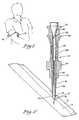
- Figure 3illustrates the invented needle with the cannula fully disposed in the blood vessel and the trocar partially removed from the cannula.
- Figure 4illustrates the invented needle with the trocar fully removed from the cannula.
- the invented needlecan be used for dialysis, blood transfusions, blood donations, intravenous feeding, femoral artery and vein catheterization, peritoneal dialysis, and any other medical intravenous or other fluid transfer applications in which the rate of liquid flow into or out of the body of a patient should be optimized.
- FIG 1a patient is shown with the invented needle 10 inserted into his arm and a tube 12 for providing liquid communication to a liquid source or receptacle, such as dialysis equipment, IV supply bottles, a blood or fluid collection receptacle and the like, which may be attached to the tube 12.
- a liquid source or receptaclesuch as dialysis equipment, IV supply bottles, a blood or fluid collection receptacle and the like, which may be attached to the tube 12.
- the present inventioncan be used for any of the above-identified purposes. Although the following description generally refers to its use in connection with withdrawal of blood from a blood vessel, it will be obvious to one skilled in the art that the present invention can be applied in any medical applications environment to obtain the desired results.
- the needle 10has two primary components, namely, a trocar 14 and a cannula 16.
- the trocar 14may be either hollow or solid and, as shown in Figure 2, the trocar is similar to a hollow needle, such as a standard hypodermic needle.
- a pointed tip 18 of the trocar 14extends below the end 20 of the cannula 16 a sufficient distance so that when the tip 18 is inserted into the blood vessel 17, only the unthreaded end 20 of the cannula 16 will have penetrated the skin 15.
- the threads 22should be equidistantly spaced apart, notwithstanding the changing diameter of the cannula 16. This spatial arrangement of the threads insures that the cannula can be evenly and fully screwed in without cross-threading.
- the end 20 of the cannulais preferably blunt to avoid injury to the blood vessel or other tissue in which the needle is inserted. Particularly with respect to blood vessels, there is a concern that if end 20 is not sufficiently blunt, it may injure or pass completely through the vessel causing a hematoma so that it cannot draw blood therefrom or otherwise deposit fluid into the blood stream.
- the end 20 including the threads 22 of the cannulais preferably made of flexible material to further prevent injury to the blood vessel, and, in addition, to permit the cannula 16 to bend in the direction of the blood vessel. In this way, the cannula 16 can be inserted down stream or upstream in the blood vessel to perform a catherization, or simply to secure the cannula in the blood vessel.
- the threaded portion 22can be shorter or longer then that depicted in the drawings, and can have portions which are conically shaped and/or cylindrical through its length, as required, to achieve the desired result.
- the cannula 16may have apertures 21 therealong to increase the number of potential fluid pathways to decrease the resistance to flow.
- apertures 21Without apertures 21, the only entry or exit point for fluid into the cannula 16 is through end 20 thereof. However, with apertures 21 disposed in cannula 16 along the portion thereof disposed in the blood vessel 17 or other fluid filled target area, the blood can flow through the apertures 21 thereby providing additional volume to permit blood flow therethrough.
- the trocar 14is attached to the cannula 16 by a coupling means which can reversibly couple and uncouple the trocar 14 from the cannula 16.
- a coupling meanswhich can reversibly couple and uncouple the trocar 14 from the cannula 16.
- the middle portion of the trocar 14comprises externally disposed threads 24 and the middle portion of the cannula 16 comprises internally disposed threads 26.
- the cannula threads 26preferably mate tightly with the trocar threads 24, forming a substantially fluid tight seal so that there is no blood leakage past the threads.
- both the trocar neck portion 28 and the cannula neck 38are preferably translucent or transparent so that the user can observe when blood or other fluid flows therein. In this way, when the user is inserting the needle in a blood vessel, blood will appear in the neck portion when the needle is properly inserted in the vessel.
- the cannula neck portion 38is flexible so that it can be clamped to prevent blood flow therethrough after the trocar 14 is removed from within the cannula 16.
- a cap 34is disposed over the end 36 thereof to prevent blood leakage therefrom before the tube 12 shown in Figure 1 is attached to the proximal end 30 of the cannula 16.
- the inside diameter of the cannula 16 at distal end 20is approximately equal to the outside diameter of the trocar 14 and thus, the smallest interior diameter of the cannula 16 is substantially relatively larger than the internal diameter of the trocar 14 or other standard dialysis needle.
- the present inventionis not deemed to be limited in any way by the preferred diameter size ranges set forth herein.
- the end 20 of the cannula 16is relatively tightly sealed against the tip 18 of the trocar 14 so that the cannula can fit into the hole made by the trocar. In this configuration, minimal trauma is caused to the skin, tissue and blood vessels when the cannula is inserted therein. However, the cannula end 20 does not so tightly engage the trocar end 18 that the trocar 14 cannot be removed from cannula 16.
- the ridge 19 or step between the trocar 14 and cannula 16is as small as possible so as to minimize the trauma caused by insertion of the cannula 16 through the skin 15 and blood vessel 17.
- the ridge 19is smooth and flexible while the threaded portion 22 is increasingly stiff in comparison, to permit the cannula to be threaded into the blood vessel.
- the externally threaded portion 22 of the cannula 16permits the cannula 16 to be threaded into the hole in the skin 15 and blood vessel 17 without having to enlarge the hole substantially.
- the upper portion of the cannulahas a neck portion 38, above which is the end 30 which is preferably flared so that it can accommodate the trocar gripping means 32.
- the cannula neck portion 38is also formed to securely hold tubes, catheters, syringes, and the like, to be attached to the needle 10.
- a Luer-lock type of fasteneris attached to permit fast, secure and standard attachment to syringes, tubing and the like.
- the invented needlehas a beveled sharpened edge and a threaded portion thereabove, with the general shape of the needle being conical.
- a trocaris not provided. Instead, end 20 of the cannula is beveled and sharpened to cut through the skin and into the blood vessel or body cavity.
- This embodimenthas the advantages over prior art needles of greater liquid flow rate because of the conical shape.
- the threadspermit easy, less painful insertion of the needle in the patient, allowing the skin and blood vessels to stretch rather than puncturing a large hole therethrough.
- the threadsassist in securing the device in the patient by providing resistance to the needle being forced out.
- the needleIn order for the needle to be forced out, either the skin or other tissue through which the needle is disposed must be stretched over the thread, or the needle must rotate to thread itself out of the hold. This is in contrast to smooth wall cylindrical needles which need only slide directly out of the hole.
- the trocaris solid and pointed, and threaded along its exposed length.
- the cannulasurrounds the trocar, and is also threaded, as described in the above first embodiment.
- This embodimentis contemplated as being particularly useful for peritoneal dialysis in which a cannula is disposed through the fascia, a very tough membrane overlying the peritoneal cavity, and fluid is pumped into the cavity and then removed therefrom.
- the needlecan be effectively and efficiently screwed into the fascia, without the effort of puncturing the same by direct pressure.
- the trocar 14is inserted through the skin 15 and into the blood vessel 17 until the cannula threads 22 are adjacent the skin 15.
- the cannula 16is rotated using the cannula grip means 40 thereby screwing the cannula 16 through the skin 15 and into the blood vessel 17.
- the trocar 14is held stationary so that it is not inserted into the blood vessel any further than originally disposed in the initial insertion shown in Figure 2.
- trocar neck 28ais exposed outside the cannula end 30a. In this position, trocar tip 18a is approximately in the same position with respect to blood vessel 17a as trocar tip 18 is to blood vessel 17 in Figure 2.
- Figure 3illustrates the position of the elements of the invented needle 10 after the cannula 16a is fully inserted in the blood vessel 17a and the trocar 14a is partially retracted from the cannula 16a.
- the alphanumeric designation "a" in Figure 3indicates the position of each of the aforementioned elements after cannula 16a is inserted and trocar 14a is partially retracted.
- the cannula external threads 22aare screwed into the skin 15a all the way so that ridge 46a of grip means 40a is adjacent the skin, in practice, the actual distance of insertion of the cannula depends on various medical considerations generally known in the art, such as the depth of the blood vessel beneath the skin and the desired angle of penetration.
- Figure 4illustrates the invented needle 10b in use with the trocar (not shown) fully removed.
- the alphanumeric designation "b" in Figure 4indicates each of the aforementioned elements in position at this stage of operation of the present invention.
- the invention as shownallows for maximum blood flow therethrough.
- a full and completely clear channelhas been created within cannula 16b, the narrowest portion thereof being the cannula tip 20b.
- the inside diameter of the cannula 16is at least slightly larger than the outside diameter of the trocar 14.
- the present inventionpermits a much greater blood flow through the needle 10 than prior art needles, which are generally only the size of the trocar, or smaller and are cylindrically shaped, rather than conical.
- the fact that the cannulais screwed into the skin and blood vessel rather than having it punched in allows the cannula to be of substantially larger diameter than a standard dialysis needle.
- tube 12bis attached with a conical end (Luer-lock) to the end 32b of cannula 16b.
- Lucent-locka conical end
- the invented needle 10bis removed from the patient.
- the needle 10bis rotated, thereby screwing it out of the blood vessel 17b and skin 15b.
- Generally known medical proceduresare then utilized to stop the bleeding.
Landscapes
- Health & Medical Sciences (AREA)
- Engineering & Computer Science (AREA)
- Life Sciences & Earth Sciences (AREA)
- General Health & Medical Sciences (AREA)
- Veterinary Medicine (AREA)
- Anesthesiology (AREA)
- Biomedical Technology (AREA)
- Heart & Thoracic Surgery (AREA)
- Hematology (AREA)
- Animal Behavior & Ethology (AREA)
- Biophysics (AREA)
- Public Health (AREA)
- Pulmonology (AREA)
- Chemical & Material Sciences (AREA)
- Manufacturing & Machinery (AREA)
- Materials Engineering (AREA)
- Mechanical Engineering (AREA)
- Metallurgy (AREA)
- Organic Chemistry (AREA)
- Infusion, Injection, And Reservoir Apparatuses (AREA)
- External Artificial Organs (AREA)
- Manufacture And Refinement Of Metals (AREA)
Abstract
Description
- This invention relates to cannulas and hypodermic needles, and more particularly, to a hypodermic needle having a threaded portion to secure said needle in a body and an enlarged internal diameter for optimized flow rate of liquids passing therethrough.
- Needles for application or insertion into an artery, vein or other blood vessel or cavity are utilized for the withdrawal of blood from a blood vessel, or body cavity, and/or the delivery of blood or other fluid to such blood vessel or body cavity. One common usage of such needles is in hemo-dialysis in which blood is removed from a patient, purified and returned to the patent. In dialysis and other medical procedures relating to the injection and/or withdrawal of fluids in the body, it is desirable and generally important to optimize the rate at which the blood or other liquid flows through the needle. The major limitation in the rate of blood flow is the size of the cross-sectional area of the needle, since the tubing used to carry the blood to the dialysis equipment is of significantly greater diameter than the needle. Generally, the larger the cross-sectional area of a needle is throughout its length, the greater the flow rate of the liquid therethrough. In fact, the rate of flow of a liquid through a needle is proportional to the radius (r) of the needle raised to the fourth power and inversely proportional to the length of the needle, according to Hagen-Poiseulle's equation, set forth

Q = flow
r = radius of conduit
Δ P = pressure gradient
L = length of conduit= constant
- The pressure gradient (ΔP) that can safely be applied to the blood is limited by the capacity of the blood cells to withstand the pressure without hemolyzing (rupturing). High negative pressure results in damage to the cell membrane and hemolysis. Therefore, the only means to optimize flow through the needle is to modify the radius and the length of the needle. The length is difficult to modify because of certain inherent factors such as the distance of the target blood vessel to the surface of the skin and the best or preferred angle for inserting the needle into the blood vessel. Therefore, the best and most common parameter of the above equation which is modified to increase the fluid flow through a needle is the radius.
- In the case of kidney dialysis, the criticality of the rate of blood flow for dialysis patients can be better understood when it is considered that each adult kidney patient requiring dialysis must receive dialysis treatment three times a week for his or her life, and each such treatment requires typically approximately four hours to complete. Thus, ignoring other factors, according to Poiseulle's equation, the doubling of the internal diameter of a needle throughout its length would result in a sixteen-fold increase in the rate of blood flow, which, in turn, would result in a sixteen-fold time reduction for each dialysis treatment. Accordingly, a reduction in treatment time, in turn, would reduce the cost of dialysis treatment substantially. Even a 10 percent increase in needle diameter results in approximately a 46 percent (1.1⁴) increase in flow rate. Prior art dialysis needles have an internal diameter in the range of approximately 1.6 to 2.2 mm (generally, 16 gauge needles are used), which is generally larger than those used for hypodermic injections. Such needles are also generally manufactured with ultrathin wall thicknesses of 0.05 to 0.1 mm to obtain the smallest possible outer diameter with the greatest possible inner diameter.
- Of course, there are inherent problems involved with using needles having particularly large cross-sectional diameters (e.g. large gauge needles). For example, large gauge needles tend to be more painful to a patient than smaller needles. Also, the larger puncture wound caused by a large gauge needle requires greater healing time. Further, larger gauge needles have a greater risk of infection as a result of the aforementioned larger hole and longer healing time. There is also a psychological factor involved, in that persons who are afraid of needles tend to have a greater fear of larger gauge needles.
- Further, in this connection, it is also known that skin and blood vessels are flexible and elastic and can stretch to some degree when stretched at a reasonably slow rate. Needles used for dialysis, except for the beveled point used to cut a hole in the skin and blood vessel, are substantially of a uniform diameter throughout their length. Thus, prior art needles do not effectively rely on the ability of the skin and blood vessel to stretch to permit the insertion of a needle of relatively large diameter into a relatively small hole, but instead, cut a relatively large hole.
- In addition, prior art needles, particularly those intended to remain in place for extended periods of time, have certain inherent problems with respect to their ability to remain fixed in place when inserted in the intended blood vessel or body cavity. In particular, such needles must be held in place by adhesive or other securing means; otherwise, the needle is easily displaced because the smooth sides thereof do not create enough resistance to be held in place.
- From FR-A-2 466 994 a needle is known which consists of a cannula and a trocar. For placing the needle into a cavity of a patient a fixing element in form of a table element with pointed bars is used. After fixing said bars in the skin of a patient the needle is driven through the skin by means of pushing element and then screwed into a bone or vessel whereby the table element acts as a stabilizer. Such an arrangement is painful for a patient and only suitable to puncture bones but not for inserting into vessels of a patient.
- The present invention overcomes the drawbacks of the prior art needles, providing a needle having a large internal diameter capable of being inserted into a blood vessel without puncturing a large hole in the skin and blood vessel or body cavity, which needle is securely disposed in a predetermined area.
- The present invention comprises a needle for insertion into a blood vessel, body organ, body cavity and the like, having a pointed or sharpened puncturing member which creates a small hole in the skin, blood vessel or other internal tissue, thereby allowing a larger diameter threaded conical member to be threaded therein, thus stretching rather than cutting or tearing a hole in the patient. The inner diameter of the needle is enlarged even more when the puncturing member is removed, leaving only a short portion with relatively narrow diameter, the majority of the length of the needle having a substantially larger internal diameter than any prior art needle.
- The invented needle comprises a hollow or solid trocar, said trocar having a sharpened point or bevel on one end thereof, and a conically shaped cannula disposed tightly around the trocar and removably attached thereto. The sharpened end of the trocar extends past the end of the cannula. The cannula is externally threaded near its end adjacent the trocar sharpened end so that it can be screwed into the skin and blood vessel, or other tissue without excessively enlarging the hole by insertion thereof. The end of the cannula is blunt and flexible to prevent damage to the tissue, vessel or organ in which it is placed, and to permit the cannula to bend in line with the vessel. The cannula may also include holes along its end to increase the fluid flow therein.
- The trocar is removably attached to and preferably screwed into the cannula. If the trocar is hollow, a cap may be provided thereon to prevent leakage of blood therethrough after the needle is inserted into a blood vessel, until the trocar is removed from the cannula. With a hollow trocar, the ends of the cannula and trocar, respectively, opposite the sharpened end are preferably translucent or transparent so that when the device is properly inserted in its predetermined target area, such as a blood vessel, the user can observe blood flowing into the neck of the device to insure that the needle has been properly placed. This transparent region is preferably formed of flexible material so that it can be clamped to prevent fluid flow therethrough until the tubing or other receptacle is attached to the end of the needle.
- In another embodiment of the present invention, the needle is conically shaped and hollow with a sharpened beveled end and threads on the exterior surface thereof. In this embodiment, there is no trocar, and the sharpened end of the cannula serves the same purpose. This embodiment has the advantages of having a larger diameter throughout the majority of its length so that an increased fluid flow capacity can be achieved relative to a standard, smooth, bare cylindrical needle. In addition, the threaded portion of the needle is held in place by the threads so that cumbersome procedures for securing the needle in place may be relaxed. Moreover, the threaded conical shape of the needle enables the user to puncture a small hole which can be stretched into a larger hole, rather than puncturing a larger hole to accommodate the large diameter of the conical needle.
- In use, to insert the invented needle into a blood vessel, body organ, body cavity, or the like, of a human or animal patient, first, the tip of the trocar is inserted up to the external threads on the cannula. The user can detect when the trocar tip is inserted into the blood vessel by observing the flow of blood into the needle through the transparent portion thereof.
- In the second step the cannula is screwed into the blood vessel, body cavity or organ, or the like, over the trocar. In this manner, the skin and blood vessel surrounding the needle are stretched, rather than torn or cut by the cannula having a larger outer diameter than the trocar. Simultaneously with the threading of the cannula into the intended location, the trocar is removed therefrom so that it does not puncture a hole in the side of the blood vessel opposite the point of entry. In the preferred embodiment, the trocar is screwed out of the cannula as the cannula is screwed into the blood vessel. In this way an internal diameter of the cannula, which is greater than that of the trocar, is freely exposed.
- The larger internal cross-sectional area of the cannula allows the blood or other fluid to flow at a faster rate than smaller conventional hypodermic or dialysis needles. Moreover, the hole actually cut by the invented needle is the same size or smaller than that of the prior art needles. When the dialysis or other treatment is completed, the cannula can be screwed out, and the skin and blood vessel around the hole are permitted to relax thereby partially closing up the hole.
- Figure 1 shows a patient with the invented needle disposed in his arm.
- Figure 2 is a cross-sectional side view of the invented needle disposed in a blood vessel.
- Figure 3 illustrates the invented needle with the cannula fully disposed in the blood vessel and the trocar partially removed from the cannula.
- Figure 4 illustrates the invented needle with the trocar fully removed from the cannula.
- The invented needle can be used for dialysis, blood transfusions, blood donations, intravenous feeding, femoral artery and vein catheterization, peritoneal dialysis, and any other medical intravenous or other fluid transfer applications in which the rate of liquid flow into or out of the body of a patient should be optimized.
- In Figure 1, a patient is shown with the invented
needle 10 inserted into his arm and atube 12 for providing liquid communication to a liquid source or receptacle, such as dialysis equipment, IV supply bottles, a blood or fluid collection receptacle and the like, which may be attached to thetube 12. - As described herein, the present invention can be used for any of the above-identified purposes. Although the following description generally refers to its use in connection with withdrawal of blood from a blood vessel, it will be obvious to one skilled in the art that the present invention can be applied in any medical applications environment to obtain the desired results.
- As shown in Figure 2, one embodiment of the invented
needle 10 is shown disposed through theskin 15 and into the interior of ablood vessel 17. Theneedle 10 has two primary components, namely, atrocar 14 and acannula 16. Thetrocar 14 may be either hollow or solid and, as shown in Figure 2, the trocar is similar to a hollow needle, such as a standard hypodermic needle. A pointed tip 18 of thetrocar 14 extends below theend 20 of the cannula 16 a sufficient distance so that when the tip 18 is inserted into theblood vessel 17, only theunthreaded end 20 of thecannula 16 will have penetrated theskin 15. - With respect to the conical shape of the
cannula 16, particularly with respect to thethreads 22 thereon, it is important to note that thethreads 22 should be equidistantly spaced apart, notwithstanding the changing diameter of thecannula 16. This spatial arrangement of the threads insures that the cannula can be evenly and fully screwed in without cross-threading. Theend 20 of the cannula is preferably blunt to avoid injury to the blood vessel or other tissue in which the needle is inserted. Particularly with respect to blood vessels, there is a concern that ifend 20 is not sufficiently blunt, it may injure or pass completely through the vessel causing a hematoma so that it cannot draw blood therefrom or otherwise deposit fluid into the blood stream. - The
end 20 including thethreads 22 of the cannula is preferably made of flexible material to further prevent injury to the blood vessel, and, in addition, to permit thecannula 16 to bend in the direction of the blood vessel. In this way, thecannula 16 can be inserted down stream or upstream in the blood vessel to perform a catherization, or simply to secure the cannula in the blood vessel. The threadedportion 22 can be shorter or longer then that depicted in the drawings, and can have portions which are conically shaped and/or cylindrical through its length, as required, to achieve the desired result. In addition, thecannula 16 may have apertures 21 therealong to increase the number of potential fluid pathways to decrease the resistance to flow. Without apertures 21, the only entry or exit point for fluid into thecannula 16 is throughend 20 thereof. However, with apertures 21 disposed incannula 16 along the portion thereof disposed in theblood vessel 17 or other fluid filled target area, the blood can flow through the apertures 21 thereby providing additional volume to permit blood flow therethrough. - The
trocar 14 is attached to thecannula 16 by a coupling means which can reversibly couple and uncouple thetrocar 14 from thecannula 16. In the preferred embodiment shown in Figure 2, the middle portion of thetrocar 14 comprises externally disposed threads 24 and the middle portion of thecannula 16 comprises internally disposedthreads 26. Thecannula threads 26 preferably mate tightly with the trocar threads 24, forming a substantially fluid tight seal so that there is no blood leakage past the threads. - Above the trocar threads 24 is a
neck portion 28 extending up to the end 30 of thecannula 16. In the preferred embodiment, a grippingmeans 32 is attached to theend 36 of thetrocar 14. In use, the grippingmeans 32 is used to facilitate gripping thetrocar 14 to screw it out of thecannula 16. If the trocar is hollow, both thetrocar neck portion 28 and the cannula neck 38 are preferably translucent or transparent so that the user can observe when blood or other fluid flows therein. In this way, when the user is inserting the needle in a blood vessel, blood will appear in the neck portion when the needle is properly inserted in the vessel. Preferably, the cannula neck portion 38 is flexible so that it can be clamped to prevent blood flow therethrough after thetrocar 14 is removed from within thecannula 16. - Also in the preferred embodiment, if the trocar is hollow, a
cap 34 is disposed over theend 36 thereof to prevent blood leakage therefrom before thetube 12 shown in Figure 1 is attached to the proximal end 30 of thecannula 16. - The inside diameter of the
cannula 16 atdistal end 20 is approximately equal to the outside diameter of thetrocar 14 and thus, the smallest interior diameter of thecannula 16 is substantially relatively larger than the internal diameter of thetrocar 14 or other standard dialysis needle. However, as one skilled in the art will readily recognize, the present invention is not deemed to be limited in any way by the preferred diameter size ranges set forth herein. - The
end 20 of thecannula 16 is relatively tightly sealed against the tip 18 of thetrocar 14 so that the cannula can fit into the hole made by the trocar. In this configuration, minimal trauma is caused to the skin, tissue and blood vessels when the cannula is inserted therein. However, thecannula end 20 does not so tightly engage the trocar end 18 that thetrocar 14 cannot be removed fromcannula 16. In the preferred embodiment, the ridge 19 or step between thetrocar 14 andcannula 16 is as small as possible so as to minimize the trauma caused by insertion of thecannula 16 through theskin 15 andblood vessel 17. The ridge 19 is smooth and flexible while the threadedportion 22 is increasingly stiff in comparison, to permit the cannula to be threaded into the blood vessel. - The externally threaded
portion 22 of thecannula 16 permits thecannula 16 to be threaded into the hole in theskin 15 andblood vessel 17 without having to enlarge the hole substantially. Once theneedle 10 is inserted into the patient up to theend 20 of the cannula, the cannula is screwed into theskin 15 and theblood vessel 17, as shown in Figure 3. A grippingmeans 40 is provided to hold and rotate thecannula 16 with respect to thetrocar 14 and also with respect to the patient. - The upper portion of the cannula has a neck portion 38, above which is the end 30 which is preferably flared so that it can accommodate the
trocar gripping means 32. The cannula neck portion 38 is also formed to securely hold tubes, catheters, syringes, and the like, to be attached to theneedle 10. Preferably, a Luer-lock type of fastener is attached to permit fast, secure and standard attachment to syringes, tubing and the like. - In another embodiment, the invented needle has a beveled sharpened edge and a threaded portion thereabove, with the general shape of the needle being conical. However in this embodiment, a trocar is not provided. Instead, end 20 of the cannula is beveled and sharpened to cut through the skin and into the blood vessel or body cavity. This embodiment has the advantages over prior art needles of greater liquid flow rate because of the conical shape. Of course, it is not essential that the entire length of the needle be conically shaped, and it is contemplated that a portion of the length of said needle be cylindrically shaped. As described above, the threads permit easy, less painful insertion of the needle in the patient, allowing the skin and blood vessels to stretch rather than puncturing a large hole therethrough. Moreover, the threads assist in securing the device in the patient by providing resistance to the needle being forced out. In order for the needle to be forced out, either the skin or other tissue through which the needle is disposed must be stretched over the thread, or the needle must rotate to thread itself out of the hold. This is in contrast to smooth wall cylindrical needles which need only slide directly out of the hole.
- In yet another embodiment of the present invention, the trocar is solid and pointed, and threaded along its exposed length. The cannula surrounds the trocar, and is also threaded, as described in the above first embodiment. This embodiment is contemplated as being particularly useful for peritoneal dialysis in which a cannula is disposed through the fascia, a very tough membrane overlying the peritoneal cavity, and fluid is pumped into the cavity and then removed therefrom. In this application, it is very difficult to force the cannula through the fascia, and great force must be applied thereto when using prior art needles. However, using this embodiment, the needle can be effectively and efficiently screwed into the fascia, without the effort of puncturing the same by direct pressure.
- In operation, as shown in Figure 2, the
trocar 14 is inserted through theskin 15 and into theblood vessel 17 until thecannula threads 22 are adjacent theskin 15. At that point, thecannula 16 is rotated using the cannula grip means 40 thereby screwing thecannula 16 through theskin 15 and into theblood vessel 17. Simultaneously with rotaing thecannula 16, thetrocar 14 is held stationary so that it is not inserted into the blood vessel any further than originally disposed in the initial insertion shown in Figure 2. As shown in Figure 3, trocar neck 28a is exposed outside thecannula end 30a. In this position, trocar tip 18a is approximately in the same position with respect to blood vessel 17a as trocar tip 18 is toblood vessel 17 in Figure 2. - Figure 3 illustrates the position of the elements of the invented
needle 10 after the cannula 16a is fully inserted in the blood vessel 17a and the trocar 14a is partially retracted from the cannula 16a. The alphanumeric designation "a" in Figure 3 indicates the position of each of the aforementioned elements after cannula 16a is inserted and trocar 14a is partially retracted. It should particularly be noted that although as shown in Figure 3, the cannula external threads 22a are screwed into the skin 15a all the way so that ridge 46a of grip means 40a is adjacent the skin, in practice, the actual distance of insertion of the cannula depends on various medical considerations generally known in the art, such as the depth of the blood vessel beneath the skin and the desired angle of penetration. - Figure 4 illustrates the invented needle 10b in use with the trocar (not shown) fully removed. The alphanumeric designation "b" in Figure 4 indicates each of the aforementioned elements in position at this stage of operation of the present invention. The invention as shown allows for maximum blood flow therethrough. A full and completely clear channel has been created within cannula 16b, the narrowest portion thereof being the
cannula tip 20b. The inside diameter of thecannula 16 is at least slightly larger than the outside diameter of thetrocar 14. The present invention permits a much greater blood flow through theneedle 10 than prior art needles, which are generally only the size of the trocar, or smaller and are cylindrically shaped, rather than conical. Moreover, the fact that the cannula is screwed into the skin and blood vessel rather than having it punched in allows the cannula to be of substantially larger diameter than a standard dialysis needle. - It is anticipated that blood flow in the range of 500 to 1,000 milliliters per minute can be obtained using the invented needle as compared with a flow rate of 200 to 300 milliliters per minute for a prior art dialysis needle. Accordingly, the time required for dialysis treatment of an adult is reduced from 4 hours per treatment using a prior art needle to approximately 1 1/2 to 2 hours for a complete dialysis treatment using the present invention.
- Also, as shown in Figure 4, tube 12b is attached with a conical end (Luer-lock) to the end 32b of cannula 16b. When the medical procedure is terminated, the invented needle 10b is removed from the patient. To accomplish removal, the needle 10b is rotated, thereby screwing it out of the blood vessel 17b and skin 15b. Generally known medical procedures are then utilized to stop the bleeding.
- The sizes and relative distances presented are for illustration purposes and should not be construed to limit the scope of the invention. The steps in the operation of the present invention illustrate the preferred method of the inventor and are not, in any way, intended to limit the scope of the present invention.


Claims (8)
- A needle (10) for use in the removal of body fluids and injection of liquids therein with a high volume liquid flow rate therethrough comprising:
a trocar (14) having a pointed first end (18), a central portion and a gripping means (32) on a second end; and
a cannula (16) comprising:
a first end (20) and second end (30), said cannula (16) being disposed about said trocar (14) so that said point (18) extends beyond said first end (20) of said cannula (16);
an externally threaded portion (22) on said first end (20) so that said first end (20) can be threaded into a patient's skin and blood vessel with minimal trauma thereto; and
a gripping means (32, 40) to facilitate the threading of said cannula (16) into and out of said skin and blood vessel; whereby said needle (10) can be inserted into a blood vessel up to said sharpened point (18) of said trocar (14), said cannula (16) can be srewed into said blood vessel and said trocar (14) can be removed from said cannula (16) thereby creating an enlarged conduit for the passage of fluid therethrough,
characterized in that inner and outer portions of said cannula (16) are conically shaped such as to comprise a short portion with relatively narrow diameter at its distal end (20), whereas the majority of the length of the cannula (16) having a substantially larger internal diameter. - The needle of claim 1 wherein said central portion of said trocar (14) comprises an externally threaded portion (24) and said cannula (16) comprises an internally threaded portion (26) between said first and second ends (20; 30) adapted to mate with said externally threaded portion (24) of said trocar (14) whereby said trocar (14) is removably attached to said cannula (16) by said internally threaded portion (26).
- The needle of claim 1 or 2 wherein said cannula (16) further comprises a connection means on said second end (30) for connecting said cannula (16) to a receptacle.
- The needle of claim 1 wherein said first end (20) of said cannula (16) further comprises apertures (21) disposed therealong for providing fluid communication therethrough.
- The needle of claim 1 wherein said trocar (14) is eithera) hollow and comprising a beveled point (18) on said first end and further comprises preferably a cap means (34) thereon for preventing the flow of liquid through said trocar (14)
orb) solid. - The needle of claim 1 wherein said first end of said trocar (14) is threaded along its length.
- The needle of claims 1-6 wherein said trocar (14) and said cannula (16) further comprise substantially transparent portions therealong so that fluid contained in said needle (10) can be viewed therethrough, said substantially transparent portion of said cannula (16) being preferably formed of flexible material so that said cannula (16) can be clamped closed to prevent fluid flow therethrough.
- A hypodermic cannula (16) comprising a sharpened beveled end (18), a threaded portion (20) thereabove for threading said cannula (10) into a patient, and an attachment means for attaching said cannula to a receptacle or source, characterized in that inner and outer portions of said cannula (16) are conically shaped such as to comprise a short portion with relatively narrow diameter at its distal end (20), whereas the majority of the length of the cannula (16) having a substantially larger internal diameter.
Priority Applications (1)
| Application Number | Priority Date | Filing Date | Title |
|---|---|---|---|
| AT87903813TATE82515T1 (en) | 1987-06-01 | 1987-06-01 | HIGH FLOW THREADED NEEDLE. |
Applications Claiming Priority (1)
| Application Number | Priority Date | Filing Date | Title |
|---|---|---|---|
| US06/750,892US4670008A (en) | 1985-07-01 | 1985-07-01 | High flux threaded needle |
Publications (3)
| Publication Number | Publication Date |
|---|---|
| EP0317555A1 EP0317555A1 (en) | 1989-05-31 |
| EP0317555A4 EP0317555A4 (en) | 1989-11-14 |
| EP0317555B1true EP0317555B1 (en) | 1992-11-19 |
Family
ID=25019555
Family Applications (1)
| Application Number | Title | Priority Date | Filing Date |
|---|---|---|---|
| EP87903813AExpired - LifetimeEP0317555B1 (en) | 1985-07-01 | 1987-06-01 | High flux threaded needle |
Country Status (4)
| Country | Link |
|---|---|
| US (1) | US4670008A (en) |
| EP (1) | EP0317555B1 (en) |
| KR (2) | KR890701782A (en) |
| WO (1) | WO1988009678A1 (en) |
Families Citing this family (103)
| Publication number | Priority date | Publication date | Assignee | Title |
|---|---|---|---|---|
| US4804365A (en)* | 1987-02-13 | 1989-02-14 | C. R. Bard | Vascular cannulae for transfemoral cardiopulmonary bypass and method of use |
| EP0305417B1 (en)* | 1987-02-20 | 1995-06-28 | DRAENERT, Klaus, Dr.med. | Suction drainage-bone screw |
| US4861341A (en)* | 1988-07-18 | 1989-08-29 | Woodburn Robert T | Subcutaneous venous access device and needle system |
| US5484442A (en)* | 1988-10-24 | 1996-01-16 | Cook Incorporated | Intraosseous needle |
| US5601559A (en)* | 1988-10-24 | 1997-02-11 | Cook Incorporated | Intraosseous needle |
| US5009643A (en)* | 1989-08-09 | 1991-04-23 | Richard Wolf Medical Instruments Corp. | Self-retaining electrically insulative trocar sleeve and trocar |
| US5217441A (en)* | 1989-08-15 | 1993-06-08 | United States Surgical Corporation | Trocar guide tube positioning device |
| US5336206A (en)* | 1989-08-15 | 1994-08-09 | United States Surgical Corporation | Trocar penetration depth indicator and guide tube positioning device |
| US5395342A (en)* | 1990-07-26 | 1995-03-07 | Yoon; Inbae | Endoscopic portal |
| US6224608B1 (en)* | 1990-08-10 | 2001-05-01 | United States Surgical Corporation | Tissue holding device and method |
| US5645557A (en)* | 1990-12-18 | 1997-07-08 | Yoon; Inbae | Safety penetrating instrument with triggered penetrating member retraction and safety member protrusion |
| US5645556A (en)* | 1990-12-18 | 1997-07-08 | Yoon; Inbae | Safety penetrating instrument with triggered penetrating member retraction and single or multiple safety member protrusion |
| US5827315A (en)* | 1994-01-04 | 1998-10-27 | Yoon; Inbae | Safety penetrating instrument with penetrating member protected after penetration to predetermined depth |
| US5330501A (en)* | 1991-05-30 | 1994-07-19 | United States Surgical Corporation | Tissue gripping device for use with a cannula and a cannula incorporating the device |
| US5330432A (en)* | 1991-12-06 | 1994-07-19 | Inbae Yoon | Retractable safety penetrating instrument |
| US5324268A (en)* | 1991-12-16 | 1994-06-28 | Inbae Yoon | Trocar with safety shield |
| US5360405A (en)* | 1991-11-27 | 1994-11-01 | Inbae Yoon | Automatic retractable safety penetrating instrument |
| US5645076A (en)* | 1991-08-14 | 1997-07-08 | Yoon; Inbae | Automatic retractable safety penetrating instrument |
| US5445617A (en)* | 1991-11-27 | 1995-08-29 | Yoon; Inbae | Automatic retractable safety penetrating instrument for portal sleeve introduction and method of use |
| US5209736A (en)* | 1991-10-18 | 1993-05-11 | Ethicon, Inc. | Trocar method and apparatus |
| US5545142A (en)* | 1991-10-18 | 1996-08-13 | Ethicon, Inc. | Seal members for surgical trocars |
| DE69228257T2 (en)* | 1991-11-06 | 1999-07-08 | Inbae M.D. Phoenix Yoon, Md. | HOLDER FOR SURGICAL INSTRUMENTS |
| US5226890A (en)* | 1991-11-13 | 1993-07-13 | United States Surgical Corporation | Tissue gripping device |
| US5573511A (en)* | 1991-11-27 | 1996-11-12 | Yoon; Inbae | Retractable safety penetrating instrument with safety probe |
| US5584849A (en)* | 1991-11-27 | 1996-12-17 | Yoon; Inbae | Retractable safety penetrating instrument with safety shield and multiple triggering and/or moving components |
| CA2124860C (en)* | 1991-11-27 | 1998-12-15 | Inbae Yoon | Retractable safety penetrating instrument for portal sleeve introduction |
| US5603719A (en)* | 1991-11-27 | 1997-02-18 | Yoon; Inbae | Retractable safety trocar with multiple triggering and/or moving components |
| US5665072A (en)* | 1991-11-27 | 1997-09-09 | Yoon; Inbae | Safety needle instrument with movable cannula and needle |
| US5779680A (en)* | 1991-11-27 | 1998-07-14 | Yoon; Inbae | Retractable safety needle instrument with movable safety member |
| US5707362A (en)* | 1992-04-15 | 1998-01-13 | Yoon; Inbae | Penetrating instrument having an expandable anchoring portion for triggering protrusion of a safety member and/or retraction of a penetrating member |
| US5375588A (en)* | 1992-08-17 | 1994-12-27 | Yoon; Inbae | Method and apparatus for use in endoscopic procedures |
| US5540648A (en)* | 1992-08-17 | 1996-07-30 | Yoon; Inbae | Medical instrument stabilizer with anchoring system and methods |
| US5342315A (en)* | 1993-04-12 | 1994-08-30 | Ethicon, Inc. | Trocar seal/protector assemblies |
| US5437645A (en)* | 1993-10-08 | 1995-08-01 | United States Surgical Corporation | Surgical instrument positioning device |
| US5538509A (en)* | 1994-01-31 | 1996-07-23 | Richard-Allan Medical Industries, Inc. | Trocar assembly |
| US5637088A (en)* | 1995-09-14 | 1997-06-10 | Wenner; Donald E. | System for preventing needle displacement in subcutaneous venous access ports |
| US5957888A (en)* | 1995-10-10 | 1999-09-28 | United States Surgical Corporation | Surgical cannula having a variable length |
| US5964732A (en) | 1997-02-07 | 1999-10-12 | Abbeymoor Medical, Inc. | Urethral apparatus with position indicator and methods of use thereof |
| US5906595A (en)* | 1997-04-25 | 1999-05-25 | Ethicon Endo-Surgery, Inc. | Trocar having protector with flexible end and improved seal assembly |
| US5971967A (en)* | 1997-08-19 | 1999-10-26 | Abbeymoor Medical, Inc. | Urethral device with anchoring system |
| US6004302A (en)* | 1997-08-28 | 1999-12-21 | Brierley; Lawrence A. | Cannula |
| US6019776A (en)* | 1997-10-14 | 2000-02-01 | Parallax Medical, Inc. | Precision depth guided instruments for use in vertebroplasty |
| US6033411A (en)* | 1997-10-14 | 2000-03-07 | Parallax Medical Inc. | Precision depth guided instruments for use in vertebroplasty |
| US7572263B2 (en) | 1998-04-01 | 2009-08-11 | Arthrocare Corporation | High pressure applicator |
| WO1999049819A1 (en)* | 1998-04-01 | 1999-10-07 | Parallax Medical, Inc. | Pressure applicator for hard tissue implant placement |
| AU6168699A (en) | 1999-03-24 | 2000-10-09 | Parallax Medical, Inc. | Non-compliant system for delivery of implant material |
| US6210376B1 (en) | 1999-04-08 | 2001-04-03 | New York University | Cannulated delivery pin |
| DE19916088A1 (en) | 1999-04-09 | 2000-10-26 | Storz Karl Gmbh & Co Kg | Device for creating a transcutaneous access to an internal hollow organ |
| US6783515B1 (en) | 1999-09-30 | 2004-08-31 | Arthrocare Corporation | High pressure delivery system |
| US6638265B1 (en)* | 2000-06-08 | 2003-10-28 | Artin M. Ternamian | Laparoscopy cannula adapter and assembly |
| US20020049489A1 (en)* | 2000-07-11 | 2002-04-25 | Herweck Steve A. | Prosthesis and method of making a prosthesis having an external support structure |
| US7008433B2 (en)* | 2001-02-15 | 2006-03-07 | Depuy Acromed, Inc. | Vertebroplasty injection device |
| US8641715B2 (en) | 2002-05-31 | 2014-02-04 | Vidacare Corporation | Manual intraosseous device |
| US8668698B2 (en) | 2002-05-31 | 2014-03-11 | Vidacare Corporation | Assembly for coupling powered driver with intraosseous device |
| US11298202B2 (en) | 2002-05-31 | 2022-04-12 | Teleflex Life Sciences Limited | Biopsy devices and related methods |
| US10973545B2 (en) | 2002-05-31 | 2021-04-13 | Teleflex Life Sciences Limited | Powered drivers, intraosseous devices and methods to access bone marrow |
| EP2039298B1 (en) | 2002-05-31 | 2017-10-25 | Vidacare LLC | Apparatus to access bone marrow |
| US11337728B2 (en) | 2002-05-31 | 2022-05-24 | Teleflex Life Sciences Limited | Powered drivers, intraosseous devices and methods to access bone marrow |
| US20040073139A1 (en)* | 2002-10-11 | 2004-04-15 | Hirsch Joshua A. | Cannula for extracting and implanting material |
| ES2545328T3 (en) | 2003-03-14 | 2015-09-10 | Depuy Spine, Inc. | Bone cement hydraulic injection device in percutaneous vertebroplasty |
| US8066713B2 (en) | 2003-03-31 | 2011-11-29 | Depuy Spine, Inc. | Remotely-activated vertebroplasty injection device |
| US9504477B2 (en) | 2003-05-30 | 2016-11-29 | Vidacare LLC | Powered driver |
| US8415407B2 (en) | 2004-03-21 | 2013-04-09 | Depuy Spine, Inc. | Methods, materials, and apparatus for treating bone and other tissue |
| US8579908B2 (en) | 2003-09-26 | 2013-11-12 | DePuy Synthes Products, LLC. | Device for delivering viscous material |
| US8673021B2 (en)* | 2003-11-26 | 2014-03-18 | Depuy Mitek, Llc | Arthroscopic tissue scaffold delivery device |
| US20060064101A1 (en)* | 2004-02-12 | 2006-03-23 | Arthrocare Corporation | Bone access system |
| CN101065080B (en) | 2004-07-30 | 2021-10-29 | 德普伊新特斯产品有限责任公司 | Materials and Instruments for Manipulating Bone and Other Tissues |
| US20060079922A1 (en)* | 2004-10-12 | 2006-04-13 | Brian Creston | Balloon anchored surgical apparatus, its use and manufacture |
| US7935122B2 (en)* | 2004-12-23 | 2011-05-03 | Arthrocare Corporation | Cannula having asymmetrically-shaped threads |
| US20060164913A1 (en)* | 2005-01-21 | 2006-07-27 | Arthrocare Corporation | Multi-chamber integrated mixing and delivery system |
| US8235942B2 (en) | 2005-05-04 | 2012-08-07 | Olympus Endo Technology America Inc. | Rotate-to-advance catheterization system |
| US8343040B2 (en) | 2005-05-04 | 2013-01-01 | Olympus Endo Technology America Inc. | Rotate-to-advance catheterization system |
| US8317678B2 (en) | 2005-05-04 | 2012-11-27 | Olympus Endo Technology America Inc. | Rotate-to-advance catheterization system |
| US7780650B2 (en)* | 2005-05-04 | 2010-08-24 | Spirus Medical, Inc. | Rotate-to-advance catheterization system |
| US8414477B2 (en) | 2005-05-04 | 2013-04-09 | Olympus Endo Technology America Inc. | Rotate-to-advance catheterization system |
| US9381024B2 (en) | 2005-07-31 | 2016-07-05 | DePuy Synthes Products, Inc. | Marked tools |
| US9918767B2 (en) | 2005-08-01 | 2018-03-20 | DePuy Synthes Products, Inc. | Temperature control system |
| US9283314B2 (en)* | 2005-09-21 | 2016-03-15 | Abiomed, Inc. | Cannula systems |
| US8360629B2 (en) | 2005-11-22 | 2013-01-29 | Depuy Spine, Inc. | Mixing apparatus having central and planetary mixing elements |
| US8574220B2 (en) | 2006-02-28 | 2013-11-05 | Olympus Endo Technology America Inc. | Rotate-to-advance catheterization system |
| US8435229B2 (en) | 2006-02-28 | 2013-05-07 | Olympus Endo Technology America Inc. | Rotate-to-advance catheterization system |
| US8147453B2 (en) | 2006-03-13 | 2012-04-03 | Applied Medical Resources Corporation | Balloon trocar |
| US8287503B2 (en)* | 2006-03-13 | 2012-10-16 | Applied Medical Resources Corporation | Balloon trocar |
| EP3189787B1 (en) | 2006-09-12 | 2019-01-09 | Teleflex Medical Devices S.à.r.l. | Medical procedures trays and related methods |
| US8944069B2 (en) | 2006-09-12 | 2015-02-03 | Vidacare Corporation | Assemblies for coupling intraosseous (IO) devices to powered drivers |
| EP2073728B1 (en) | 2006-09-12 | 2018-11-07 | Teleflex Medical Devices S.à.r.l. | Biopsy device |
| AU2007297097A1 (en) | 2006-09-14 | 2008-03-20 | Depuy Spine, Inc. | Bone cement and methods of use thereof |
| US20080097347A1 (en)* | 2006-09-22 | 2008-04-24 | Babak Arvanaghi | Bendable needle assembly |
| US8950929B2 (en) | 2006-10-19 | 2015-02-10 | DePuy Synthes Products, LLC | Fluid delivery system |
| AU2007329469A1 (en)* | 2006-12-01 | 2008-06-12 | The Board Of Trustees Of The Leland Stanford Junior University | Devices and methods for accessing the epidural space |
| US20080154304A1 (en)* | 2006-12-21 | 2008-06-26 | Arthrocare Corporation | System and method for accessing a tissue structure |
| US8870755B2 (en) | 2007-05-18 | 2014-10-28 | Olympus Endo Technology America Inc. | Rotate-to-advance catheterization system |
| US20100023065A1 (en)* | 2008-07-25 | 2010-01-28 | Welch Andrea M | Tissue access device with alignment guide and methods of use |
| BRPI0917035A2 (en) | 2008-12-04 | 2019-09-24 | Pivot Medical Inc | "telescope access cannula, telescope shutter, system, method for providing an access corridor from a first off-site location to a second on-site location" |
| US20100256483A1 (en)* | 2009-04-03 | 2010-10-07 | Insite Medical Technologies, Inc. | Devices and methods for tissue navigation |
| US8343035B2 (en)* | 2009-04-20 | 2013-01-01 | Spine View, Inc. | Dilator with direct visualization |
| US20110054448A1 (en)* | 2009-08-28 | 2011-03-03 | Navilyst Medical, Inc. | Medical device containing catheter anchoring feature |
| EP2485663B1 (en) | 2009-10-09 | 2017-03-22 | Applied Medical Resources Corporation | Trocar with retention cannula |
| US8888692B1 (en) | 2011-08-26 | 2014-11-18 | Applied Medical Resources Corporation | Trocar cannula assembly and method of manufacture |
| KR102301914B1 (en) | 2013-03-15 | 2021-09-15 | 어플라이드 메디컬 리소시스 코포레이션 | Trocar cannula assembly with low profile insertion configuration and method of manufacture |
| WO2019108618A1 (en) | 2017-11-28 | 2019-06-06 | Pneumonix Medical, Inc. | Apparatus and method to seal a tissue tract |
| US11517666B2 (en)* | 2017-12-15 | 2022-12-06 | Spinal Generations, Llc | Intraosseous needle assembly and method of use thereof |
| USD935611S1 (en) | 2018-12-10 | 2021-11-09 | Pneumonix Medical, Inc. | Tissue tract sealant device |
Citations (1)
| Publication number | Priority date | Publication date | Assignee | Title |
|---|---|---|---|---|
| DE1541237A1 (en)* | 1966-08-27 | 1969-07-10 | Bertram Fa Ludwig | Trocar |
Family Cites Families (11)
| Publication number | Priority date | Publication date | Assignee | Title |
|---|---|---|---|---|
| US1248492A (en)* | 1917-04-10 | 1917-12-04 | A D Haskell | Paracentesis needle or trocar. |
| US1888349A (en)* | 1932-02-15 | 1932-11-22 | Charles M Jacoby | Catheter |
| US3727613A (en)* | 1970-10-09 | 1973-04-17 | Voys Inc Le | Safety catheter placement assembly |
| US3815605A (en)* | 1971-05-19 | 1974-06-11 | Philips Corp | Device and holder therefor for inserting a hollow coupling member into bone marrow |
| DE2218901C3 (en)* | 1972-04-19 | 1981-06-11 | Karl 7200 Tuttlingen Storz | Trocar for introducing surgical instruments into body cavities |
| US4013080A (en)* | 1974-10-03 | 1977-03-22 | Froning Edward C | Cannula connector and direction indicator means for injection system |
| US4013808A (en)* | 1974-12-30 | 1977-03-22 | Midwest Precision Corporation | Sealed caster |
| US4191191A (en)* | 1978-02-13 | 1980-03-04 | Auburn Robert M | Laproscopic trocar |
| US4215690A (en)* | 1978-02-16 | 1980-08-05 | Oreopoulos Dimitrios G | Medical needle |
| FR2466994A1 (en)* | 1979-10-11 | 1981-04-17 | Emerit Andre | Medical needle directs liq. radially into or from flesh - partic. for intramuscular anaesthetic injection or draining venom from snake bite |
| GB2130890B (en)* | 1982-11-30 | 1987-07-29 | Downs Surgical Plc | Aspiration needle |
- 1985
- 1985-07-01USUS06/750,892patent/US4670008A/ennot_activeExpired - Lifetime
- 1987
- 1987-05-26KRKR1019890700136Apatent/KR890701782A/ennot_activeWithdrawn
- 1987-06-01EPEP87903813Apatent/EP0317555B1/ennot_activeExpired - Lifetime
- 1987-06-01KRKR1019890700180Apatent/KR890701148A/ennot_activeWithdrawn
- 1987-06-01WOPCT/US1987/001272patent/WO1988009678A1/enactiveIP Right Grant
Patent Citations (1)
| Publication number | Priority date | Publication date | Assignee | Title |
|---|---|---|---|---|
| DE1541237A1 (en)* | 1966-08-27 | 1969-07-10 | Bertram Fa Ludwig | Trocar |
Also Published As
| Publication number | Publication date |
|---|---|
| KR890701782A (en) | 1989-12-21 |
| US4670008A (en) | 1987-06-02 |
| KR890701148A (en) | 1989-12-19 |
| WO1988009678A1 (en) | 1988-12-15 |
| EP0317555A4 (en) | 1989-11-14 |
| EP0317555A1 (en) | 1989-05-31 |
Similar Documents
| Publication | Publication Date | Title |
|---|---|---|
| EP0317555B1 (en) | High flux threaded needle | |
| KR102373798B1 (en) | Catheter systems and methods for introducing an intravenous catheter into a patient | |
| US3323523A (en) | Intravenous catheter assembly with divisible needle sheath portions | |
| US11738179B2 (en) | Guidewire retention device | |
| US3537451A (en) | Intravenous catheter unit with releasable inserter means | |
| US3633579A (en) | Catheter placement device and method | |
| EP0568258B1 (en) | A vascular access device | |
| US4650473A (en) | Suturing saddle | |
| US6213978B1 (en) | Intravenous catheter insertion apparatus | |
| EP0593181B1 (en) | Introducer sheaths | |
| US6500157B2 (en) | Intravenous infusion needle with soft body | |
| JP4354564B2 (en) | adapter | |
| US4177809A (en) | Intravenous catheter apparatus and method | |
| US4412832A (en) | Peelable catheter introduction device | |
| US5944695A (en) | Multiple sheath catheter using multiple stages and method of use | |
| US8079979B2 (en) | Trapping of intravenous needle associated with a long catheter, and related methods | |
| US5290244A (en) | Syringe and needle with guide wire for cannulation of central veins | |
| US3559643A (en) | Catheter placement unit | |
| US20040193119A1 (en) | Catheter port assembly for extracorporeal treatment | |
| JPS62167571A (en) | Liquid sampling or injecting apparatus | |
| JPH10511029A (en) | catheter | |
| JPH0412146B2 (en) | ||
| KR20180037216A (en) | Drilling system | |
| JPS6251632B2 (en) | ||
| US20120078095A1 (en) | High-flow tapered peripheral iv catheter with side outlets |
Legal Events
| Date | Code | Title | Description |
|---|---|---|---|
| PUAI | Public reference made under article 153(3) epc to a published international application that has entered the european phase | Free format text:ORIGINAL CODE: 0009012 | |
| AK | Designated contracting states | Kind code of ref document:A1 Designated state(s):AT BE CH DE FR GB IT LI LU NL SE | |
| 17P | Request for examination filed | Effective date:19890613 | |
| A4 | Supplementary search report drawn up and despatched | Effective date:19891114 | |
| 17Q | First examination report despatched | Effective date:19901026 | |
| GRAA | (expected) grant | Free format text:ORIGINAL CODE: 0009210 | |
| AK | Designated contracting states | Kind code of ref document:B1 Designated state(s):AT BE CH DE FR GB IT LI LU NL SE | |
| REF | Corresponds to: | Ref document number:82515 Country of ref document:AT Date of ref document:19921215 Kind code of ref document:T | |
| RBV | Designated contracting states (corrected) | Designated state(s):DE FR IT | |
| REF | Corresponds to: | Ref document number:3782738 Country of ref document:DE Date of ref document:19921224 | |
| ET | Fr: translation filed | ||
| ITF | It: translation for a ep patent filed | ||
| NLXE | Nl: other communications concerning ep-patents (part 3 heading xe) | Free format text:IN PAT.BUL.24/92 SHOULD BE DELETED | |
| PLBE | No opposition filed within time limit | Free format text:ORIGINAL CODE: 0009261 | |
| STAA | Information on the status of an ep patent application or granted ep patent | Free format text:STATUS: NO OPPOSITION FILED WITHIN TIME LIMIT | |
| 26N | No opposition filed | ||
| PGFP | Annual fee paid to national office [announced via postgrant information from national office to epo] | Ref country code:FR Payment date:19950619 Year of fee payment:9 | |
| PGFP | Annual fee paid to national office [announced via postgrant information from national office to epo] | Ref country code:DE Payment date:19950815 Year of fee payment:9 | |
| PG25 | Lapsed in a contracting state [announced via postgrant information from national office to epo] | Ref country code:FR Effective date:19970228 | |
| PG25 | Lapsed in a contracting state [announced via postgrant information from national office to epo] | Ref country code:DE Effective date:19970301 | |
| REG | Reference to a national code | Ref country code:FR Ref legal event code:ST | |
| PG25 | Lapsed in a contracting state [announced via postgrant information from national office to epo] | Ref country code:IT Free format text:LAPSE BECAUSE OF NON-PAYMENT OF DUE FEES;WARNING: LAPSES OF ITALIAN PATENTS WITH EFFECTIVE DATE BEFORE 2007 MAY HAVE OCCURRED AT ANY TIME BEFORE 2007. THE CORRECT EFFECTIVE DATE MAY BE DIFFERENT FROM THE ONE RECORDED. Effective date:20050601 |