EP0316908B1 - Process for the measurement of mass flow rate using the coriolis principle and mass flow rate measuring apparatus using the coriolis principle - Google Patents
Process for the measurement of mass flow rate using the coriolis principle and mass flow rate measuring apparatus using the coriolis principleDownload PDFInfo
- Publication number
- EP0316908B1 EP0316908B1EP88119127AEP88119127AEP0316908B1EP 0316908 B1EP0316908 B1EP 0316908B1EP 88119127 AEP88119127 AEP 88119127AEP 88119127 AEP88119127 AEP 88119127AEP 0316908 B1EP0316908 B1EP 0316908B1
- Authority
- EP
- European Patent Office
- Prior art keywords
- measuring tube
- mass flow
- flow meter
- tube wall
- meter according
- Prior art date
- Legal status (The legal status is an assumption and is not a legal conclusion. Google has not performed a legal analysis and makes no representation as to the accuracy of the status listed.)
- Expired - Lifetime
Links
- 238000000034methodMethods0.000titleclaimsdescription15
- 238000005259measurementMethods0.000titledescription13
- 230000010355oscillationEffects0.000claimsdescription17
- 239000012530fluidSubstances0.000claimsdescription16
- 230000005284excitationEffects0.000claimsdescription11
- 230000000737periodic effectEffects0.000claimsdescription9
- 230000003287optical effectEffects0.000claimsdescription6
- 230000004907fluxEffects0.000claimsdescription5
- 229910052594sapphireInorganic materials0.000claimsdescription5
- 239000010980sapphireSubstances0.000claimsdescription5
- 230000002093peripheral effectEffects0.000claims5
- 238000006073displacement reactionMethods0.000claims2
- 238000007654immersionMethods0.000claims1
- 230000010358mechanical oscillationEffects0.000claims1
- 230000010363phase shiftEffects0.000description16
- 238000005452bendingMethods0.000description12
- 230000005484gravityEffects0.000description8
- 238000013461designMethods0.000description3
- 230000000694effectsEffects0.000description3
- 238000004519manufacturing processMethods0.000description3
- 238000013508migrationMethods0.000description3
- 230000005012migrationEffects0.000description3
- 230000007423decreaseEffects0.000description2
- 230000002441reversible effectEffects0.000description2
- 239000000725suspensionSubstances0.000description2
- 206010038743RestlessnessDiseases0.000description1
- 210000001015abdomenAnatomy0.000description1
- 239000004020conductorSubstances0.000description1
- 230000003247decreasing effectEffects0.000description1
- 238000011161developmentMethods0.000description1
- 230000002349favourable effectEffects0.000description1
- 230000035945sensitivityEffects0.000description1
- 238000012549trainingMethods0.000description1
Images

Classifications
- G—PHYSICS
- G01—MEASURING; TESTING
- G01F—MEASURING VOLUME, VOLUME FLOW, MASS FLOW OR LIQUID LEVEL; METERING BY VOLUME
- G01F1/00—Measuring the volume flow or mass flow of fluid or fluent solid material wherein the fluid passes through a meter in a continuous flow
- G01F1/76—Devices for measuring mass flow of a fluid or a fluent solid material
- G01F1/78—Direct mass flowmeters
- G01F1/80—Direct mass flowmeters operating by measuring pressure, force, momentum, or frequency of a fluid flow to which a rotational movement has been imparted
- G01F1/84—Coriolis or gyroscopic mass flowmeters
- G01F1/8409—Coriolis or gyroscopic mass flowmeters constructional details
- G01F1/8413—Coriolis or gyroscopic mass flowmeters constructional details means for influencing the flowmeter's motional or vibrational behaviour, e.g., conduit support or fixing means, or conduit attachments
- G01F1/8418—Coriolis or gyroscopic mass flowmeters constructional details means for influencing the flowmeter's motional or vibrational behaviour, e.g., conduit support or fixing means, or conduit attachments motion or vibration balancing means
- G—PHYSICS
- G01—MEASURING; TESTING
- G01F—MEASURING VOLUME, VOLUME FLOW, MASS FLOW OR LIQUID LEVEL; METERING BY VOLUME
- G01F1/00—Measuring the volume flow or mass flow of fluid or fluent solid material wherein the fluid passes through a meter in a continuous flow
- G01F1/76—Devices for measuring mass flow of a fluid or a fluent solid material
- G01F1/78—Direct mass flowmeters
- G01F1/80—Direct mass flowmeters operating by measuring pressure, force, momentum, or frequency of a fluid flow to which a rotational movement has been imparted
- G01F1/84—Coriolis or gyroscopic mass flowmeters
- G01F1/8409—Coriolis or gyroscopic mass flowmeters constructional details
- G01F1/8422—Coriolis or gyroscopic mass flowmeters constructional details exciters
- G—PHYSICS
- G01—MEASURING; TESTING
- G01F—MEASURING VOLUME, VOLUME FLOW, MASS FLOW OR LIQUID LEVEL; METERING BY VOLUME
- G01F1/00—Measuring the volume flow or mass flow of fluid or fluent solid material wherein the fluid passes through a meter in a continuous flow
- G01F1/76—Devices for measuring mass flow of a fluid or a fluent solid material
- G01F1/78—Direct mass flowmeters
- G01F1/80—Direct mass flowmeters operating by measuring pressure, force, momentum, or frequency of a fluid flow to which a rotational movement has been imparted
- G01F1/84—Coriolis or gyroscopic mass flowmeters
- G01F1/8409—Coriolis or gyroscopic mass flowmeters constructional details
- G01F1/8427—Coriolis or gyroscopic mass flowmeters constructional details detectors
- G—PHYSICS
- G01—MEASURING; TESTING
- G01F—MEASURING VOLUME, VOLUME FLOW, MASS FLOW OR LIQUID LEVEL; METERING BY VOLUME
- G01F1/00—Measuring the volume flow or mass flow of fluid or fluent solid material wherein the fluid passes through a meter in a continuous flow
- G01F1/76—Devices for measuring mass flow of a fluid or a fluent solid material
- G01F1/78—Direct mass flowmeters
- G01F1/80—Direct mass flowmeters operating by measuring pressure, force, momentum, or frequency of a fluid flow to which a rotational movement has been imparted
- G01F1/84—Coriolis or gyroscopic mass flowmeters
- G01F1/845—Coriolis or gyroscopic mass flowmeters arrangements of measuring means, e.g., of measuring conduits
- G01F1/8463—Coriolis or gyroscopic mass flowmeters arrangements of measuring means, e.g., of measuring conduits the measuring conduits' cross-section being deformed during measurement, e.g. by periodically deflecting a portion of the conduits' surface
- G—PHYSICS
- G01—MEASURING; TESTING
- G01F—MEASURING VOLUME, VOLUME FLOW, MASS FLOW OR LIQUID LEVEL; METERING BY VOLUME
- G01F1/00—Measuring the volume flow or mass flow of fluid or fluent solid material wherein the fluid passes through a meter in a continuous flow
- G01F1/76—Devices for measuring mass flow of a fluid or a fluent solid material
- G01F1/78—Direct mass flowmeters
- G01F1/80—Direct mass flowmeters operating by measuring pressure, force, momentum, or frequency of a fluid flow to which a rotational movement has been imparted
- G01F1/84—Coriolis or gyroscopic mass flowmeters
- G01F1/845—Coriolis or gyroscopic mass flowmeters arrangements of measuring means, e.g., of measuring conduits
- G01F1/8468—Coriolis or gyroscopic mass flowmeters arrangements of measuring means, e.g., of measuring conduits vibrating measuring conduits
- G01F1/849—Coriolis or gyroscopic mass flowmeters arrangements of measuring means, e.g., of measuring conduits vibrating measuring conduits having straight measuring conduits
Definitions
- the inventionrelates to a method for mass flow measurement according to the Coriolis principle with a single fluid-flowed, elastically deformable measuring tube, which is periodically excited and in which, as a measure of the mass flow, phase shifts between deflections of sections of the measuring tube wall arranged differently in the flow direction are measured.
- the invention according to claim 8relates to a mass flow meter working according to the Coriolis principle, in particular for carrying out the above method, with a single, elastically deformable measuring tube which can be inserted into a fluid line and which is periodically excited and in which, as a measure of the mass flow, phase shifts between deflections of in Sections of the measuring tube wall arranged in different directions are measured.
- JP-A 57-137 8178It is known (JP-A 57-137 818) to carry out mass flow measurements with a single measuring tube. It is firmly clamped at both ends. In the middle, it is excited to bend vibrations transversely to the direction of flow of the fluid, ie its inner and outer profiles become in one plane along the direction of flow deformed certain period. Due to the fixed clamping at the two ends, a single half-wave with a periodically changing bulge extends over the entire length of the measuring tube. If fluid of a certain mass now flows through the measuring tube, the shape of the half-wave is distorted (out of phase) due to Coriolis forces.
- a periodic migration of the center of gravity of the measuring deviceis avoided by the opposite bulging of the measuring tube.
- an oval cross-sectionis required for the measuring tube where the vibration amplitudes are greatest (antinodes), in order to reduce the bending resistance there.
- This design of the cross-sectionleads to additional expenditure in production.
- fixed clamping pointsare necessary at the measuring tube ends to form the vibration nodes, to which torques act due to the bending vibrations.
- the generation of bending vibrationsin particular in a higher vibration mode, becomes more and more complex and difficult.
- the inventionis therefore based on the object to provide a method of the type mentioned which - while avoiding the disadvantages mentioned - can be carried out with a simple and inexpensive to manufacture and simple and compact measuring device which is reliable in operation and largely without interference on it Measurement environment is, can be operated without periodic migration of its focus and can also handle large nominal sizes.
- This objectis achieved by a method according to claim 1.
- a measuring device suitable for carrying it outis designed according to claim 8.
- a vibration modeis selected for the measuring tube, in which parts or sections of the measuring tube wall opposite one another symmetrically to the central longitudinal axis (central axis) of the measuring tube are in the same direction or in opposite directions, that is to say to each other in phase or 180 ° out of phase.
- the wallsare deflected by elastic, reversible deformation of the measuring tube cross section. If fluid of a certain mass flows from a fluid line into the periodically deformed measuring tube, it must absorb the energy of the deformation vibrations on the inlet side and release this absorbed energy on the outlet side. This means that Coriolis forces occur which delay the deformation of the measuring tube and thus the deflection of the measuring tube walls on the inlet side and accelerate it on the outlet side. The resulting phase shift of the deflections of sections of the measuring tube wall, which are arranged differently distributed over the measuring tube length, can be measured to determine the mass flow.
- the reciprocal of the period of the cross-sectional deformationsessentially coincides with one of the natural / resonance frequencies of vibrations of the circumference of the measuring tube in the radial direction. This leads to a deflection of the measuring tube walls such that the position of the gravity line of the measuring tube remains largely constant.
- periodic wanderings of the center of gravity of the measuring device and thus vibrations transmitted into its surroundingsare thus largely avoided without additional design effort being necessary.
- the resonance frequency for the circumferential vibrations of the measuring tubeis selected so that a higher-order vibration mode is created, that is, waves of the number n with n greater than zero are formed on the measuring tube wall in the circumferential direction of the measuring tube. Vibration nodes with vibration bellies in between, each numbering twice n, are created over the circumference of the measuring tube.
- An additional problemis to achieve sufficient sensitivity and / or vibration stability.
- Thisis countered with a further embodiment of the invention, according to which bending vibrations are excited in addition to the circumferential vibrations in the measuring tube. It appears particularly advantageous if, on the one hand, a mode is selected for the bending vibrations in which two half-waves with a vibration node in the middle of the measuring tube are created along the measuring tube (second-order mode). This vibration node contributes to increasing the stability of the frequency of the circumferential vibrations on which the mass flow measurement is based. It appears to be particularly advantageous to choose the mode with the atomic number n equal to three or four for the circumferential vibrations.
- alternating torquesinevitably occur due to the bending vibrations at the clamping points of the measuring tube.
- Their possibly undesirable effectscan be contained or eliminated, for example, by mechanical filter arrangements consisting, for example, of mass and / or spring and / or damper elements.
- the periodic deformation of the measuring tubecan expediently be achieved in that the measuring tube walls are deflected accordingly by externally generated alternating forces directed at the measuring tube wall, the frequency of which with one of the natural / resonance frequencies of the circumferential vibrations of the measuring tube matches. As a result, the consumption of vibration energy to be applied can be reduced in order to achieve a sufficient measurement effect.
- forcesare applied to diametrically opposite parts or locations of the measuring tube wall which are 180 ° out of phase with one another.
- the measuring tubeis loaded mirror-symmetrically to its central axis in this area on train or pressure.
- the points of application of the forcesare preferably in the central region of the measuring tube, because there the fluid mass neither absorbs nor releases deformation energy, that is to say it attacks almost no Coriolis forces.
- the influence of any fixed clamping points of the measuring tube, which counteracts the deflection of the measuring tube wall,is lowest.
- two measuring pointsare arranged as far apart as possible for this purpose. They are preferably provided in the vicinity of the inlet and outlet ends of the measuring tube.
- the vibration exciter which generates the periodic deformations of the measuring tubeis constructed and arranged in such a way that the measuring tube wall is deflected substantially uniformly with respect to the central axis or gravity line of the measuring tube and perpendicular to the direction of flow of the fluid.
- the wall movementscompensate each other in such a way that the original balance of the measuring device is largely maintained.
- the circumferential vibrations of the measuring tubeare generated by a single vibration exciter, which is in operative connection with at least part of the measuring tube wall.
- a vibration exciterwhich is in operative connection with at least part of the measuring tube wall.
- imbalancesare caused on the measuring tube.
- a compensating bodyis attached to the area of the measuring tube wall which is diametrically opposite the vibration exciter.
- measuring tubescan be used which have a shape symmetrical to their longitudinal axis, such as a cylindrical shape. It is advantageous to use measuring tubes that are polygonal in cross-section to the direction of flow. If, for example, the measuring tube has a square cross-sectional shape, the four corners each form zones in which the measuring tube walls experience almost no deflection (vibration nodes). On the other hand, this means that zones with maximum deflection of the measuring tube wall occur mainly in the central areas of the side sections formed by the corners (antinodes). This creates areas on the measuring tube wall that have particularly favorable conditions for detecting the phase shift.
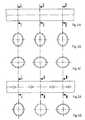
- FIGS. 1A-1Dradial circumferential vibrations are impressed on a measuring tube 1 for flow measurement according to the invention, the frequencies of which correspond to the natural resonance frequencies of the measuring tube in the circumferential vibration mode.
- the number n according to FIGS. 1A-1Ddenotes the order of the vibration modes and gives the number of the wavelengths which extend over the circumference of the measuring tube. According to the arrows in FIGS.
- the wall 2 of the measuring tube 1is always deflected in the radial direction either towards the center of the measuring tube cross section or away from it. Any vibration nodes that occur along the cross-section of the measuring tube are designated by the letter K in FIGS. 1A-1D.
- the flow direction of the fluidruns perpendicular to the measuring tube cross-section into the plane of the drawing.
- the circumference of the measuring tube 1is zero in the oscillation mode n. This means that no shaft and no antinodes and nodes form over the circumference of the measuring tube.
- the diameter of the measuring tube 1increases or decreases with a period duration corresponding to a certain resonance frequency uniformly over the measuring tube wall forming the circumference of the measuring tube.
- the circumference of the measuring tube 1is two in vibration mode n.
- diametrically opposite wall parts of the measuring tube 1are each deflected in opposite directions, that is to say in the opposite direction.
- the circumference of the measuring tube 1is four in the oscillation mode n, which means four waves with eight oscillation nodes evenly distributed over the circumference of the measuring tube 1. Otherwise, the explanations for FIG. 1B apply accordingly.
- the circumference of the measuring tube 1is three in the oscillation mode n, which means three wavelengths with six oscillation nodes evenly distributed over the circumference of the measuring tube.
- diametrically opposite wall partsunless they coincide with the areas of the vibration nodes K, are deflected in the same direction, that is to say in the same direction in each case.
- vibration nodes with n greater than or equal to twoare generally known as "HOOPE vibration modes”.
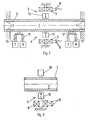
- the mass flow measuring deviceessentially has a measuring tube 1, a first and second vibration exciter 5, 6 and two optical sensor devices T, R.
- the wall of the measuring tube 1 forming the cavity through which fluid flowsis shown in longitudinal section in FIG.
- the inlet-side end 3 and the outlet-side end 4 of the measuring tube 1are each firmly clamped.
- free suspension of the measuring tube ends 3, 4is also possible.
- the first and second vibration exciters 5, 6are arranged in such a way that they lie opposite one another symmetrically to the central axis of the measuring tube 1 (shown in broken lines).
- the electromechanical vibration exciters 5, 6essentially each have an excitation coil 9 supplied with alternating current via the connections 8 and a permanent magnet 10 with south pole S and north pole N which is connected to it.
- the permanent magnets 10are attached directly to the measuring tube wall 2, while the excitation coils 9 are fixed externally.
- the optical sensors T, Rare arranged in the inlet or outlet-side area and essentially consist of a light transmitter T, a light guide device 11, a light receiver R and plungers 12 attached directly to the measuring tube wall 2.
- the mode of operationis as follows: If an alternating current of a certain frequency flows through the excitation coils 9, the permanent magnets 10 are alternately attracted and repelled with a certain period. Accordingly, forces act on the measuring tube wall 2, so that it is alternately loaded with tension and pressure with a certain period. This leads to elastically reversible deformations of the cross-section of the measuring tube 1. With mass flow, these deformations and the associated deflections of the measuring tube wall 2 are out of phase over the length of the measuring tube 1. The phase shift corresponds to movements of the plungers 12 attached to the measuring tube wall 2 which are shifted in time. The plungers 12 each protrude into a gap formed by the light guide device 11.
- the light guide deviceconsists of two rods made of light-conducting material, for example sapphire rods.
- the transmitter Tgenerates a luminous flux which reaches the light receiver R via the light guide device 11, including the (air) gap formed by it.
- the strength of the transmitted luminous fluxdepends on the depth with which the plungers protrude into the (air) gap. The deeper they protrude, the lower the luminous flux.
- the depth at which the plungers 11 protrude into the gapis determined by the deflection of the measuring tube wall 2.
- the difference between the two light intensities provided by the optical sensors T, Ris a measure of the time shift or phase shift of the deformation of the cross section of the measuring tube over its length.
- FIG. 3it is also within the scope of the invention to carry out the vibration excitation with a single vibration exciter 6. If this is realized electromagnetically as in FIG. 2 with excitation coils and permanent magnets 10 attached to the measuring tube wall 2, then a weight-based compensation of the mass of the permanent magnet 10 is expedient.
- a compensating body 20is provided. This can be attached from the outside to the wall 2 of the measuring tube 1 in the area which is diametrically opposite the wall area to which the permanent magnet 10 is attached.
- the mass / weight of the compensating body 20is dimensioned such that imbalances caused by the permanent magnet are compensated for. Otherwise, the part of the measuring arrangement not shown in FIG. 3 can be designed as in FIG. 2.
- FIGS. 4A-C and 5A and BThe functioning of the flow measurement according to the invention is further illustrated in FIGS. 4A-C and 5A and B.
- FIG. 4Athe essential longitudinal section of the measuring tube of a mass flow meter is shown schematically. It must be assumed that the section line II - II (shown in broken lines) lies approximately in the central area of the measuring tube.
- the vibration excitation systemas can be embodied, for example, according to FIGS. 2 or 3, is expediently arranged there.
- the section lines I - I and III - IIIindicate the positions at which the sensors for detecting the phase shift are located over the length of the measuring tube.
- FIG. 4Ait is assumed in the illustration according to FIG. 4A that there is no mass flow through the measuring tube. If the vibration excitation system is put into operation, the cross-section of the measuring tube is deformed approximately oval over its entire length, as shown in FIGS. 4B and 4C.
- FIGS. 4B and 4Crepresent separate snapshots that are staggered from one another in time, the time offset corresponding to a phase shift of the excited measuring tube vibrations of approximately 180 °. This means that the circumferential sections of the measuring tube wall, which according to FIG. 4B compared to the initial cross section according to FIG Dashed line are deflected outwards, according to Figure 4C are pressed towards the inside of the measuring tube.
- the deformations of the cross sections of the measuring tubeare largely in phase with one another in the areas of lines I - I, II - II and III - III, because no Coriolis forces attack due to the lack of mass flow.
- the cross section of the measuring tube according to line I - I of FIG. 5Ais deformed differently than that according to line III - III of FIG. 5A, as indicated in FIG. 5B by means of the solid lines (greatly exaggerated).
- the dashed line in FIG. 5Bshows the measuring tube cross section as it would look without impressing deformation vibrations.
- the cross section without deformation vibrationscoincides with that when the deformation vibrations are impressed.
- the phase shiftis preferably measured on the wall sections designated by the section lines I - I and III - III. The phase shift increases or decreases with increasing or decreasing mass flow.
Landscapes
- Physics & Mathematics (AREA)
- Fluid Mechanics (AREA)
- General Physics & Mathematics (AREA)
- Measuring Volume Flow (AREA)
Description
Translated fromGermanDie Erfindung betrifft nach Anspruch 1 ein Verfahren zur Massendurchflußmessung nach dem Coriolisprinzip mit einem einzigen von Fluid durchströmten, elastisch verformbaren Meßrohr, das periodisch erregt wird und bei dem als Maß für den Massendurchfluß Phasenverschiebungen zwischen Auslenkungen von in Strömungsrichtung unterschiedlich angeordneten Abschnitten der Meßrohrwand gemessen werden.According to
Ferner betrifft die Erfindung nach Anspruch 8 ein nach dem Coriolisprinzip arbeitendes Massendurchflußmeßgerät, insbesondere zur Durchführung des obigen Verfahrens, mit einem einzigen in eine Fluidleitung einfügbaren, elastisch verformbaren Meßrohr, das periodisch erregt wird und bei dem als Maß für den Massendurchfluß Phasenverschiebungen zwischen Auslenkungen von in Strömungsrichtung unterschiedlich angeordneten Abschnitten der Meßrohrwand gemessen werden.Furthermore, the invention according to
Es ist bekannt (JP-A 57-137 818), Massendurchlußmessungen mit einem einzigen Meßrohr durchzuführen. Dabei ist es an seinen beiden enden fest eingespannt. In seiner Mitte wird es zu Biegeschwingungen quer zur Strömungsrichtung des Fluids angeregt, d.h. sein Innen- und sein Außenprofil werden in einer Ebene entlang der Strömungsrichtung mit bestimmter Periodendauer verformt. Aufgrund der festen Einspannung an den beiden Enden erstreckt sich über die gesamte Meßrohrlänge eine einzige Halbwelle mit sich periodisch ändernder Ausbauchung. Fließt nun Fluid bestimmter Masse durch das Meßrohr, wird aufgrund auftretender Corioliskräfte die Form der Halbwelle verzerrt (phasenverschoben).It is known (JP-A 57-137 818) to carry out mass flow measurements with a single measuring tube. It is firmly clamped at both ends. In the middle, it is excited to bend vibrations transversely to the direction of flow of the fluid, ie its inner and outer profiles become in one plane along the direction of flow deformed certain period. Due to the fixed clamping at the two ends, a single half-wave with a periodically changing bulge extends over the entire length of the measuring tube. If fluid of a certain mass now flows through the measuring tube, the shape of the half-wave is distorted (out of phase) due to Coriolis forces.
Allerdings verursachen diese Biegeschwingungen in Form einer einzigen Halbwelle eine periodische Wanderung des Schwerpunkts des Massendurchflußmessers. Die Schwerpunktswanderung führt in der Regel zu Vibrationen des Gehäuses des Meßgerätes und der Fluidleitung, in welche der Massendurchflußmesser eingefügt ist. Diese auf die Umgebung übertragenen Vibrationen führen zu einem Verlust an Biegeschwingungsenergie des Meßrohres. Ist die Energieabgabe einlaufseitig und auslaufseitig unterschiedlich, zum Beispiel wegen unterschiedlich fester Einspannungen des Meßrohres, wirkt sich dies auf die zu messenden Phasenverschiebungen aus. Insbesondere kann es zu Verschiebungen des Nullpunkts der Phasenverschiebung und mithin zu Meßungenauigkeiten kommen.However, these bending vibrations in the form of a single half-wave cause a periodic shift in the center of gravity of the mass flow meter. The shift in the center of gravity usually leads to vibrations of the housing of the measuring device and the fluid line into which the mass flow meter is inserted. These vibrations transmitted to the environment lead to a loss of bending vibration energy of the measuring tube. If the energy output on the inlet side and outlet side is different, for example due to differently firm clampings of the measuring tube, this has an effect on the phase shifts to be measured. In particular, there may be shifts in the zero point of the phase shift and therefore measurement inaccuracies.
Ferner ist es bekannt (DE-PS 35 05 166), Massendurchflußmessungen mit zwei Meßrohren durchzuführen. Dabei sind die beiden Meßrohre einlauf- und auslaufseitig mittels zweier Rohrverbinder strömungstechnisch parallel geschaltet. Die Meßrohre werden jeweils in gegensinnige Biegeschwingungen versetzt, so daß die Wände des ersten Meßrohres zu denen des zweiten Meßrohres um 180 Grad phasenverschoben ausgelenkt werden. Dadurch wird eine Wanderung des Schwerpunkts des Massendurchflußmessers vermieden. Allerdings ist ein schwingendes Meßrohrsystem mit mindestens zwei Meßrohren notwendig.Furthermore, it is known (DE-PS 35 05 166) to carry out mass flow measurements with two measuring tubes. The two measuring tubes are connected in flow terms in parallel on the inlet and outlet sides by means of two tube connectors. The measuring tubes are each set in opposing bending vibrations, so that the walls of the first measuring tube are deflected out of phase with those of the second measuring tube by 180 degrees. This avoids a migration of the center of gravity of the mass flow meter. However, a vibrating measuring tube system with at least two measuring tubes is necessary.
Bei einem Massendurchflußmesser der eingangs genannten Art (WO-A 87/06 691) ist ein einziges Meßrohr an seinen beiden Enden fest eingespannt und wird zu Biegeschwingungen in einem höheren, "antisymmetrischen" Schwingungsmode angeregt. Dem entspricht eine Biegeschwingungsform, bei der sich zwei Halbwellen über die gesamte Meßrohrlänge erstrecken. Dabei entstehen drei sogenannte Schwingungsknoten in der Meßrohrmitte, und an den beiden Meßrohrenden und zwischen den Schwingungsknoten kommt es zu einander entgegengesetzten periodischen Ausbauchungen, das heißt, es entstehen zwischen den Schwingungsknoten sogenannte Schwingungsbäuche.In the case of a mass flow meter of the type mentioned at the beginning (WO-A 87/06 691), a single measuring tube is firmly clamped at both ends and is excited to flexural vibrations in a higher, “antisymmetric” vibration mode. This corresponds to a bending mode in which there are two half-waves over the entire length of the measuring tube extend. This creates three so-called vibration nodes in the middle of the measuring tube, and at the two measuring tube ends and between the vibration nodes there are periodic bulges which are opposite to one another, that is to say so-called antinodes arise between the vibration nodes.
Zwar wird durch die gegensinnig gleiche Ausbauchung des Meßrohres eine periodische Wanderung des Schwerpunkts des Meßgeräts vermieden. Jedoch ist für das Meßrohr an den Stellen, wo die Schwingungsamplituden am größten sind (Schwingungsbäuche), ein oval ausgebildeter Querschnitt notwendig, um dort den Biegewiderstand zu vermindern. Diese Ausbildung des Querschnitts führt in der Herstellung zu einem Mehraufwand. Zudem sind an den Meßrohrenden feste Einspannstellen zur Bildung der Schwingungsknoten notwendig, an denen aufgrund der Biegeschwingungen Drehmomente angreifen. Schließlich wird mit zunehmenden Meßrohrdurchmessern (Nennweiten) die Erzeugung von Biegeschwingungen, insbesondere in einem höheren Schwingungsmode, immer aufwendiger und schwieriger.A periodic migration of the center of gravity of the measuring device is avoided by the opposite bulging of the measuring tube. However, an oval cross-section is required for the measuring tube where the vibration amplitudes are greatest (antinodes), in order to reduce the bending resistance there. This design of the cross-section leads to additional expenditure in production. In addition, fixed clamping points are necessary at the measuring tube ends to form the vibration nodes, to which torques act due to the bending vibrations. Finally, with increasing measuring tube diameters (nominal diameters), the generation of bending vibrations, in particular in a higher vibration mode, becomes more and more complex and difficult.
Der Erfindung liegt somit die Aufgabe zugrunde, ein Verfahren der eingangs genannten Art zu schaffen, das - unter Vermeidung der genannten Nachteile - mit einem einfach und kostengünstig herstellbaren sowie einfach und kompakt aufgebauten Meßgerät durchführbar ist, das im Betrieb zuverlässig und weitgehend ohne Störeinfluß auf seine Meßumgebung ist, ohne periodische Wanderung seines Schwerpunkts betreibbar ist und auch große Nennweiten bewältigen kann. Diese Aufgabe wird durch ein Verfahren nach Patentanspruch 1 gelöst. Ein zu dessen Durchführung geeignetes Meßgerät ist gemäß Patentanspruch 8 ausgebildet.The invention is therefore based on the object to provide a method of the type mentioned which - while avoiding the disadvantages mentioned - can be carried out with a simple and inexpensive to manufacture and simple and compact measuring device which is reliable in operation and largely without interference on it Measurement environment is, can be operated without periodic migration of its focus and can also handle large nominal sizes. This object is achieved by a method according to
Gemäß der Erfindung wird für das Meßrohr ein Schwingungsmode gewählt, in welchem einander symmetrisch zur mittleren Längsachse (Mittelachse) des Meßrohres gegenüberliegende Teile oder Abschnitte der Meßrohrwand gleichsinnig oder gegensinnig, das heißt zueinander in Phase oder um 180° phasenverschoben, ausgelenkt werden. Die Auslenkung der Wände wird durch elastisch-reversible Verformung des Meßrohrquerschnitts erreicht. Fließt aus einer Fluidleitung in das derart periodisch verformte Meßrohr Fluid bestimmter Masse, so muß es einlaufseitig die Energie der Verformungsschwingungen aufnehmen und auslaufseitig diese aufgenommene Energie wieder abgeben. Das bedeutet, daß Corioliskräfte auftreten, die einlaufseitig die Deformation des Meßrohres und damit die Auslenkung der Meßrohrwände verzögern und auslaufseitig beschleunigen. Die so entstehende Phasenverschiebung der Auslenkungen von Abschnitten der Meßrohrwand, die über die Meßrohrlänge unterschiedlich verteilt angeordnet sind, kann zur Bestimmung des Massendurchflusses gemessen werden.According to the invention, a vibration mode is selected for the measuring tube, in which parts or sections of the measuring tube wall opposite one another symmetrically to the central longitudinal axis (central axis) of the measuring tube are in the same direction or in opposite directions, that is to say to each other in phase or 180 ° out of phase. The walls are deflected by elastic, reversible deformation of the measuring tube cross section. If fluid of a certain mass flows from a fluid line into the periodically deformed measuring tube, it must absorb the energy of the deformation vibrations on the inlet side and release this absorbed energy on the outlet side. This means that Coriolis forces occur which delay the deformation of the measuring tube and thus the deflection of the measuring tube walls on the inlet side and accelerate it on the outlet side. The resulting phase shift of the deflections of sections of the measuring tube wall, which are arranged differently distributed over the measuring tube length, can be measured to determine the mass flow.
Bei der erfindungsgemäßen Massendurchflußmessung ist es grundsätzlich nicht mehr notwendig, das Meßrohr zu Biegeschwingungen anzuregen. Damit wird der Vorteil erzielt, daß in den Bereichen der festen Einspannung und/oder freien Aufhängung der Meßrohrenden keine Drehmomente angreifen. Ein weiterer Vorteil besteht darin, daß bei Anwendung des erfindungsgemäßen Verfahrens für große Nennweiten - im Vergleich zu herkömmlichen Meßverfahren mit in Biegeschwingungen versetzten Rohren - ein kürzeres Meßrohr verwendet werden kann.In the mass flow measurement according to the invention, it is fundamentally no longer necessary to excite the measuring tube to produce bending vibrations. This has the advantage that no torques act in the areas of the fixed clamping and / or free suspension of the measuring tube ends. Another advantage is that when the method according to the invention is used for large nominal widths, a shorter measuring tube can be used in comparison to conventional measuring methods with tubes set in bending vibrations.
Nach einer zweckmäßigen Ausbildung der Erfindung stimmt der Kehrwert der Periodendauer der Querschnittsverformungen im wesentlichen mit einer der Eigen-/Resonanzfrequenzen von Schwingungen des Umfangs des Meßrohres in Radialrichtung überein. Dadurch kommt es zu einer Auslenkung der Meßrohrwände derart, daß die Lage der Schwerelinie des Meßrohres weitgehend konstant bleibt. Mithin werden bei der erfindungsgemäßen Massendurchflußmessung periodische Wanderungen des Schwerpunktes des Meßgerätes und damit in dessen Umgebung übertragene Vibrationen weitgehend vermieden, ohne daß dabei zusätzlicher, konstruktiver Aufwand notwendig wäre.According to an expedient embodiment of the invention, the reciprocal of the period of the cross-sectional deformations essentially coincides with one of the natural / resonance frequencies of vibrations of the circumference of the measuring tube in the radial direction. This leads to a deflection of the measuring tube walls such that the position of the gravity line of the measuring tube remains largely constant. In the mass flow measurement according to the invention, periodic wanderings of the center of gravity of the measuring device and thus vibrations transmitted into its surroundings are thus largely avoided without additional design effort being necessary.
Nach einer Weiterbildung der Erfindung wird die Resonanzfrequenz für die Umfangsschwingungen des Meßrohres so ausgewählt, daß ein Schwingungsmode höherer Ordnung entsteht, das heißt es bilden sich auf der Meßrohrwand in Umfangsrichtung des Meßrohres Wellen der Anzahl n mit n größer als Null aus. Dabei entstehen über den Umfang des Meßrohrs gleichmäßig verteilt Schwingungsknoten mit dazwischenliegenden Schwingungsbäuchen, jeweils der Anzahl zweimal n.According to a development of the invention, the resonance frequency for the circumferential vibrations of the measuring tube is selected so that a higher-order vibration mode is created, that is, waves of the number n with n greater than zero are formed on the measuring tube wall in the circumferential direction of the measuring tube. Vibration nodes with vibration bellies in between, each numbering twice n, are created over the circumference of the measuring tube.
Ein zusätzlicher Problempunkt besteht darin, eine ausreichende Meßempfindlichkeit und/oder Schwingungsstabilität zu erzielen. Dem wird mit einer weiteren Ausbildung der Erfindung begegnet, nach der bei dem Meßrohr zusätzlich zu den Umfangsschwingungen Biegeschwingungen erregt werden. Vorteilhaft erscheint es dabei besonders, wenn einerseits für die Biegeschwingungen ein Mode gewählt wird, bei dem längs des Meßrohres zwei Halbwellen mit einem Schwingungsknoten in Meßrohrmitte entstehen (Mode zweiter Ordnung). Dieser Schwingungsknoten trägt zur Erhöhung der Stabilität der Frequenz der Umfangsschwingungen bei, auf welchen die Massendurchflußmessung beruht. Dabei erscheint es als besonders vorteilhaft, für die Umfangsschwingungen den Mode mit der Ordnungszahl n gleich drei oder vier zu wählen. Bei dieser Erfindungsausbildung treten unvermeidlich aufgrund der Biegeschwingungen an den Einspannstellen des Meßrohres Wechsel-Drehmomente auf. Deren gegebenenfalls unerwünschte Auswirkungen können beispielsweise durch mechanische Filteranordnungen, bestehend zum Beispiel aus Masse- und/oder Federund/oder Dämpferelementen, eingedämmt oder ausgeschaltet werden.An additional problem is to achieve sufficient sensitivity and / or vibration stability. This is countered with a further embodiment of the invention, according to which bending vibrations are excited in addition to the circumferential vibrations in the measuring tube. It appears particularly advantageous if, on the one hand, a mode is selected for the bending vibrations in which two half-waves with a vibration node in the middle of the measuring tube are created along the measuring tube (second-order mode). This vibration node contributes to increasing the stability of the frequency of the circumferential vibrations on which the mass flow measurement is based. It appears to be particularly advantageous to choose the mode with the atomic number n equal to three or four for the circumferential vibrations. In this embodiment of the invention, alternating torques inevitably occur due to the bending vibrations at the clamping points of the measuring tube. Their possibly undesirable effects can be contained or eliminated, for example, by mechanical filter arrangements consisting, for example, of mass and / or spring and / or damper elements.
Die periodische Verformung des Meßrohres läßt sich zweckmäßigerweise dadurch erzielen, daß die Meßrohrwände entsprechend ausgelenkt werden durch extern erzeugte, auf die Meßrohrwand gerichtete Wechselkräfte, deren Frequenz mit einer der Eigen-/Resonanzfrequenzen der Umfangsschwingungen des Meßrohres übereinstimmt. Dadurch läßt sich der Verbrauch an aufzubringender Schwingungsenergie zur Erzielung eines ausreichenden Meßeffektes vermindern.The periodic deformation of the measuring tube can expediently be achieved in that the measuring tube walls are deflected accordingly by externally generated alternating forces directed at the measuring tube wall, the frequency of which with one of the natural / resonance frequencies of the circumferential vibrations of the measuring tube matches. As a result, the consumption of vibration energy to be applied can be reduced in order to achieve a sufficient measurement effect.
Gemäß einer besonderen Ausbildung der Erfindung werden auf einander diametral gegenüberliegenden Teilen oder Stellen der Meßrohrwand Kräfte in Angriff gebracht, die zueinander um 180° phasenverschoben sind. Dadurch wird in diesem Bereich das Meßrohr spiegelsymmetrisch zu seiner Mittelachse auf Zug beziehungsweise Druck belastet. Hierdurch läßt sich eine gut detektierbare Auslenkung der Meßrohrwand über die Meßrohrlänge erreichen. Vorzugsweise befinden sich die Angriffsstellen der Kräfte im mittleren Bereich des Meßrohres, weil dort die Fluidmasse weder Verformungsenergie aufnimmt noch abgibt, also nahezu keine Corioliskräfte angreifen. Außerdem ist dort der Einfluß etwaiger fester Einspannstellen des Meßrohres, welcher der Auslenkung der Meßrohrwand entgegenwirkt, am geringsten.According to a special embodiment of the invention, forces are applied to diametrically opposite parts or locations of the measuring tube wall which are 180 ° out of phase with one another. As a result, the measuring tube is loaded mirror-symmetrically to its central axis in this area on train or pressure. In this way, a well detectable deflection of the measuring tube wall over the length of the measuring tube can be achieved. The points of application of the forces are preferably in the central region of the measuring tube, because there the fluid mass neither absorbs nor releases deformation energy, that is to say it attacks almost no Coriolis forces. In addition, the influence of any fixed clamping points of the measuring tube, which counteracts the deflection of the measuring tube wall, is lowest.
Um bei der Messung der Phasenverschiebung der Auslenkungen der Meßrohrwände über die Meßrohrlänge eine hohe Auflösung zu erzielen, werden hierfür zwei Meßstellen möglichst weit voneinander entfernt angeordnet. Vorzugsweise sind sie in der Nähe des einlauf- und auslaufseitigen Endes des Meßrohres vorgesehen.In order to achieve a high resolution when measuring the phase shift of the deflections of the measuring tube walls over the measuring tube length, two measuring points are arranged as far apart as possible for this purpose. They are preferably provided in the vicinity of the inlet and outlet ends of the measuring tube.
Bei einem Meßgerät zur Anwendung der Erfindung kommt es wesentlich darauf an, daß der die periodischen Verformungen des Meßrohres erzeugende Schwingungserreger so aufgebaut und angeordnet ist, daß die Meßrohrwand im wesentlichen gleichmäßig bezüglich der Mittelachse beziehungsweise Schwerelinie des Meßrohres und senkrecht zur Strömungsrichtung des Fluids ausgelenkt wird. Die Wandbewegungen kompensieren dabei einander derart, daß die ursprüngliche, schwerpunktmäßige Balance des Meßgeräts weitgehend beibehalten wird.In a measuring device for applying the invention, it is essential that the vibration exciter which generates the periodic deformations of the measuring tube is constructed and arranged in such a way that the measuring tube wall is deflected substantially uniformly with respect to the central axis or gravity line of the measuring tube and perpendicular to the direction of flow of the fluid. The wall movements compensate each other in such a way that the original balance of the measuring device is largely maintained.
Dies erfolgt nach einer besonderen Ausbildung der Erfindung dadurch, daß zwei beispielsweise elektromagnetische, elektroakustische und/oder elektrostatische Schwingungserreger jeweils mit Wandabschnitten des Meßrohres in Wirkungsverbindung stehen, die einander gegenüberliegen. Vorzugsweise sind die von den Schwingungserregern erzeugten Schwingungen zueinander um 180° phasenverschoben. Dadurch wird eine um die Schwerelinie des Meßrohres herum besonders gleichmäßige sowie gut detektierbare Verformung des Meßrohres erzielt.This takes place after a special embodiment of the invention in that two electromagnetic, electroacoustic and / or electrostatic vibration exciters, for example, are each operatively connected to wall sections of the measuring tube which are opposite one another. The vibrations generated by the vibration exciters are preferably 180 ° out of phase with one another. This results in a particularly uniform and easily detectable deformation of the measuring tube around the center of gravity of the measuring tube.
Nach einer alternativen Ausbildung der Erfindung werden die Umfangsschwingungen des Meßrohres durch einen einzigen Schwingungserreger erzeugt, der mit wenigstens einem Teil der Meßrohrwand in Wirkungsverbindung steht. Dies läßt eine besonders kostengünstige Herstellung eines Massendurchfluß-Meßgeräts möglich werden. Je nach Ausbildung des Schwingungserregers werden am Meßrohr Ungleichgewichte verursacht. Um diese auszubalancieren, wird erfindungsgemäß an dem Bereich der Meßrohrwand, der dem Schwingungserreger diametral gegenüberliegt, ein Ausgleichskörper angebracht.According to an alternative embodiment of the invention, the circumferential vibrations of the measuring tube are generated by a single vibration exciter, which is in operative connection with at least part of the measuring tube wall. This allows a particularly inexpensive manufacture of a mass flow meter. Depending on the design of the vibration exciter, imbalances are caused on the measuring tube. In order to balance these, according to the invention a compensating body is attached to the area of the measuring tube wall which is diametrically opposite the vibration exciter.
Um den Einsatz einfach aufgebauter und anwendbarer Schwingungserreger zu ermöglichen, können Meßrohre verwendet werden, die eine zu ihrer Längsachse symmetrische Form besitzen, wie zum Beispiel Zylinderform. Mit Vorteil werden Meßrohre eingesetzt, die im Schnitt quer zur Strömungsrichtung mehreckig sind. Besitzt das Meßrohr beispielsweise quadratische Querschnittsform, so bilden die vier Ecken jeweils Zonen, in denen die Meßrohrwände nahezu keine Auslenkung erfahren (Schwingungsknoten). Das bedeutet andererseits, daß Zonen mit maximaler Auslenkung der Meßrohrwand hauptsächlich in den mittleren Bereichen der von den Ecken gebildeten Seitenabschnitte auftreten (Schwingungsbäuche). Damit werden an der Meßrohrwand Bereiche geschaffen, die besonders günstige Voraussetzungen zur Detektion der Phasenverschiebung haben.To enable the use of simply constructed and applicable vibration exciters, measuring tubes can be used which have a shape symmetrical to their longitudinal axis, such as a cylindrical shape. It is advantageous to use measuring tubes that are polygonal in cross-section to the direction of flow. If, for example, the measuring tube has a square cross-sectional shape, the four corners each form zones in which the measuring tube walls experience almost no deflection (vibration nodes). On the other hand, this means that zones with maximum deflection of the measuring tube wall occur mainly in the central areas of the side sections formed by the corners (antinodes). This creates areas on the measuring tube wall that have particularly favorable conditions for detecting the phase shift.
Mit Vorteil werden zur Messung der Auslenkung der Meßrohrwände nach optischem Prinzip arbeitende Sensoren eingesetzt. Diese weisen im Vergleich zu elektromechanischen Systemen ein sehr schnelles Ansprechverhalten und damit eine geringe Eigenphasenverschiebung auf.It is advantageous to measure the deflection of the measuring tube walls Sensors working according to the optical principle are used. Compared to electromechanical systems, these have a very fast response behavior and thus a low intrinsic phase shift.
Bezüglich weiterer vorteilhafter Ausbildungen der Erfindung wird auf die Unteransprüche und auf die nachfolgende Beschreibung anhand der Zeichnungen verwiesen. Es zeigen:With regard to further advantageous embodiments of the invention, reference is made to the subclaims and to the following description with reference to the drawings. Show it:
in schematischer Darstellung Momentaufnahmen von Meßrohrquerschnitten, die in radiale Umfangsschwingungen unterschiedlicher Schwingungsmoden versetzt sind,a schematic representation of snapshots of measuring tube cross sections which are set in radial circumferential vibrations of different vibration modes,
ein Ausführungs beispiel einer erfindungsgemäßen Meßanordnung in teilweise geschnittener Ansicht,an embodiment example of a measuring arrangement according to the invention in a partially sectioned view,
eine zur Schwingungserregung nach Figur 2 alternative Ausbildung der Schwingungserregung,an alternative to the vibration excitation according to Figure 2 training the vibration excitation,
einen Längsabschnitt eines Meßrohres ohne Massendurchfluß,a longitudinal section of a measuring tube without mass flow,
Querschnitte des erfindungsgemäß verwendeten Meßrohres längs der Linien I - I, II - II und III - III der Figur 4A in einem Zeitpunkt,Cross sections of the measuring tube used according to the invention along the lines I - I, II - II and III - III of Figure 4A at a time,
Querschnitte des erfindungsgemäß verwendeten Meßrohres längs der Linien I - I, II - II und III - III der Figur 4A in einem anderen Zeitpunkt,Cross sections of the measuring tube used according to the invention along the lines I - I, II - II and III - III of Figure 4A at another time,
einen Längsschnitt eines Meßrohres mit schematisch angedeutetem Massendurchfluß unda longitudinal section of a measuring tube with a schematically indicated mass flow and
Querschnitte des erfindungsgemäß verwendeten Meßrohres längs der Linien I - I, II - II und III - III der Figur 5A in einem Zeitpunkt.Cross sections of the measuring tube used according to the invention along the lines I - I, II - II and III - III of Figure 5A at one time.
Einander entsprechende Teile in den Zeichnungen sind mit übereinstimmenden Bezugszeichen versehen.Corresponding parts in the drawings are provided with the same reference numerals.
Gemäß den Figuren 1A - 1D werden zur Durchflußmessung nach der Erfindung einem Meßrohr 1 radiale Umfangsschwingungen aufgeprägt, deren Frequenzen den Eigenresonanzfrequenzen des Meßrohres im Umfangsschwingungsmode entsprechen. Dies führt zu den oben genannten, periodischen Verformungen/Deformationen der lichten Querschnittsfläche des Meßrohres 1. Diese sind in den Figuren 1A - 1D gestrichelt angedeutet, während dort die kreisrunde, durchgezogene Linie die Meßrohrquerschnittsfläche im nicht schwingenden Ruhezustand wiedergibt. Die Zahl n gemäß Figuren 1A - 1D bezeichnet die Ordnung der Schwingungsmoden und gibt die Anzahl der Wellenlängen an, welche sich über den Umfang des Meßrohres erstrecken. Gemäß den Pfeilen in den Figuren 1A - 1D erfolgt nach der Erfindung die Auslenkung der Wand 2 des Meßrohres 1 stets in radialer Richtung entweder zum Mittelpunkt des Meßrohrquerschnitts oder von diesem weg. Etwaige entlang des Meßrohrquerschnitts auftretende Schwingungsknoten sind in den Figuren 1A - 1D mit dem Buchstaben K bezeichnet. Wie in den Figuren 1A - 1D jeweils durch einen umringten Punkt in der Querschnittsmitte des Meßrohres 1 angedeutet, verläuft die Strömungsrichtung des Fluids senkrecht zum Meßrohrquerschnitt in die Zeichenebene hinein.According to FIGS. 1A-1D, radial circumferential vibrations are impressed on a measuring
Gemäß Figur 1A befindet sich der Umfang des Meßrohres 1 im Schwingungsmode n gleich Null. Das bedeutet, daß sich über den Meßrohrumfang keine Welle und keine Schwingungsbäuche und -knoten ausbilden. Der Durchmesser des Meßrohres 1 vergrößert sich beziehungsweise verkleinert sich mit einer einer bestimmten Resonanzfrequenz entsprechenden Periodendauer gleichmäßig über die den Meßrohrumfang bildende Meßrohrwand.According to FIG. 1A, the circumference of the measuring
Gemäß Figur 1B befindet sich der Umfang des Meßrohres 1 im Schwingungsmode n gleich zwei. Das bedeutet, daß sich über den Umfang des Meßrohres 1 zwei Wellen jeweils in vollständiger Länge ausgebreitet haben, wobei sich vier Schwingungsknoten K gebildet haben, die über den Meßrohrumfang gleichmäßig verteilt und im wesentlichen im gleichen Abstand voneinander liegen. Im Bereich der zwischen den Knoten befindlichen Schwingungsbäuche werden einander diametral gegenüberliegende Wandteile des Meßrohres 1 jeweils gegensinnig, das heißt in entgegengesetzter Richtung, ausgelenkt.According to FIG. 1B, the circumference of the measuring
Gemäß Figur 1D befindet sich der Umfang des Meßrohres 1 im Schwingungsmode n gleich vier, was vier Wellen mit acht Schwingungsknoten gleichmäßig über den Umfang des Meßrohres 1 verteilt bedeutet. Im übrigen gelten hier die Ausführungen zu Figur 1B entsprechend.According to FIG. 1D, the circumference of the measuring
Gemäß Figur 1C befindet sich der Umfang des Meßrohres 1 im Schwingungsmode n gleich drei, was drei Wellenlängen mit sechs Schwingungsknoten gleichmäßig über den Meßrohrumfang verteilt bedeutet. Wie anhand der Pfeile ersichtlich, werden bei dieser Ausbildung der Erfindung diametral gegenüberliegende Wandteile, soweit sie nicht mit den Bereichen der Schwingungsknoten K zusammenfallen, gleichsinnig, das heißt jeweils in gleicher Richtung,ausgelenkt.According to FIG. 1C, the circumference of the measuring
Die Schwingungsknoten mit n größer oder gleich zwei sind allgemein als "HOOPE'sche Schwingungsmoden" bekannt.The vibration nodes with n greater than or equal to two are generally known as "HOOPE vibration modes".
Gemäß Figur 2 weist das erfindungsgemäße Massendurchfluß-Meßgerät im wesentlichen ein Meßrohr 1, einen ersten und zweiten Schwingungserreger 5, 6 sowie zwei optische Sensoreinrichtungen T, R auf. Die den von Fluid durchströmten Hohlraum bildende Wand des Meßrohres 1 ist in Figur 1 im Längsschnitt dargestellt. Wie schematisch angedeutet, sind das einlaufseitige Ende 3 und das auslaufseitige Ende 4 des Meßrohres 1 jeweils fest eingespannt. Grundsätzlich ist auch eine freie Aufhängung der Meßrohrenden 3, 4 möglich. Etwa in der Mitte des Meßrohres 1 sind der erste beziehungsweise der zweite Schwingungserreger 5, 6 derart angeordnet, daß sie einander symmetrisch zur (strichpunktiert dargestellten) Mittelachse des Meßrohres 1 gegenüberliegen. Die elektromechanischen Schwingungserreger 5, 6 weisen im wesentlichen jeweils eine über die Anschlüsse 8 mit Wechselstrom gespeiste Erregerspule 9 sowie einen damit in Wirkungsverbindung stehenden Dauermagneten 10 mit Südpol S und Nordpol N auf. Die Dauermagneten 10 sind unmittelbar an der Meßrohrwand 2 befestigt, während die Erregerspulen 9 extern fixiert sind. Die optischen Sensoren T, R sind im einlaufbeziehungsweise auslaufseitigen Bereich angeordnet und bestehen im wesentlichen aus einem Lichtsender T, einer Lichtleitereinrichtung 11, einem Lichtempfänger R und unmittelbar an der Meßrohrwand 2 angebrachten Tauchfahnen 12.According to FIG. 2, the mass flow measuring device according to the invention essentially has a measuring
Die Funktionsweise ist wie folgt: Fließt durch die Erregerspulen 9 ein Wechselstrom bestimmter Frequenz, so werden die Dauermagneten 10 mit bestimmter Periode abwechselnd angezogen und abgestoßen. Entsprechend wirken Kräfte auf die Meßrohrwand 2, so daß diese mit bestimmter Periode abwechselnd auf Zug und Druck belastet wird. Dies führt zu elastisch-reversiblen Verformungen des Querschnitts des Meßrohres 1. Bei Massendurchfluß sind diese Verformungen und die damit verbundenen Auslenkungen der Meßrohrwand 2 über die Länge des Meßrohres 1 phasenverschoben. Der Phasenverschiebung entsprechen zueinander zeitlich verschobene Bewegungen der an der Meßrohrwand 2 angebrachten Tauchfahnen 12. Die Tauchfahnen 12 ragen jeweils in einen Spalt, der von der Lichtleitereinrichtung 11 gebildet wird. Im gezeichneten Ausführungsbeispiel besteht die Lichtleitereinrichtung aus zwei Stäben aus lichtleitendem Material, beispielsweise Saphirstäben. Der Sender T erzeugt einen Lichtstrom, der über die Lichtleitereinrichtung 11 einschließlich des von ihr gebildeten (Luft-) Spalts zum Lichtempfänger R gelangt. Dabei hängt die Stärke des übertragenen Lichtstroms von der Tiefe ab, mit welcher die Tauchfahnen in den (Luft-) Spalt hineinragen. Je tiefer sie hineinragen, umso geringer ist der Lichtstrom. Die Tiefe, mit welcher die Tauchfahnen 11 in den Spalt hineinragen, wird von der Auslenkung der Meßrohrwand 2 bestimmt. Infolgedessen ist der Unterschied zwischen den beiden von den optischen Sensoren T, R gelieferten Lichtstärken ein Maß für die zeitliche Verschiebung beziehungsweise Phasenverschiebung der Verformung des Querschnitts des Meßrohres über dessen Länge.The mode of operation is as follows: If an alternating current of a certain frequency flows through the excitation coils 9, the
Gemäß Figur 3 liegt es auch im Rahmen der Erfindung, die Schwingungserregung mit einem einzigen Schwingungserreger 6 durchzuführen. Ist dieser wie nach Figur 2 elektromagnetisch mit Erregerspulen und an der Meßrohrwand 2 angebrachten Dauermagneten 10 realisiert, ist ein gewichtsmäßiger Ausgleich der Masse des Dauermagneten 10 zweckmäßig. Hierzu ist gemäß Figur 3 ein Ausgleichskörper 20 vorgesehen. Dieser kann von außen an der Wand 2 des Meßrohres 1 in dem Bereich befestigt sein, der dem Wandbereich diametral gegenüberliegt, an dem der Dauermagnet 10 befestigt ist. Die Masse/das Gewicht des Ausgleichskörpers 20 ist so bemessen, daß durch den Dauermagneten verursachte Ungleichgewichte ausgeglichen werden. Im übrigen kann der in Figur 3 nicht dargestellte Teil der Meßanordnung wie nach Figur 2 ausgeführt sein.According to FIG. 3, it is also within the scope of the invention to carry out the vibration excitation with a
Die Funktionsweise der erfindungsgemäßen Durchflußmessung ist in den Figuren 4A - C und 5A und B weiter veranschaulicht.The functioning of the flow measurement according to the invention is further illustrated in FIGS. 4A-C and 5A and B.
In Figur 4A ist der wesentliche Längsabschnitt des Meßrohres eines Massendurchfluß-Meßgerätes schematisch dargestellt. Dabei ist zu unterstellen, daß die (strichpunktiert gezeichnete) Schnittlinie II - II etwa im mittleren Bereich des Meßrohres liegt. Zweckmäßigerweise ist dort das Schwingungserregungssystem, wie es zum Beispiel gemäß Figuren 2 oder 3 ausgeführt sein kann, angeordnet. Die Schnittlinien I - I und III - III kennzeichnen die Stellen, an denen sich die Sensoren zur Erfassung der Phasenverschiebung über die Meßrohrlänge befinden. Ferner ist in der Darstellung nach Figur 4A vorausgesetzt, daß kein Massendurchfluß durch das Meßrohr existiert. Wird das Schwingungserregungssystem in Betrieb gesetzt, wird der Querschnitt des Meßrohres über dessen ganze Länge näherungsweise oval verformt, wie in den Figuren 4B und 4C dargestellt. Dort sind die Verformungen der Querschnitte längs der Linien I - I, II - II und III - III der Figur 4A jeweils mit durchgezogener Linie gezeichnet. Mit der gestrichelten Linie sind die Querschnitte angedeutet, wie sie ohne Betrieb eines Schwingungserregungssystems aussehen würden. Die Figuren 4B und 4C stellen gesonderte, voneinander zeitlich versetzte Momentaufnahmen dar, wobei der Zeitversatz einer Phasenverschiebung der erregten Meßrohrschwingungen von etwa 180° entspricht. Das bedeutet, daß die Umfangsabschnitte der Meßrohrwand, die nach Figur 4B gegenüber dem Ausgangsquerschnitt gemäß gestrichelter Linie nach außen ausgelenkt sind, nach Figur 4C zum Meßrohrinneren hin eingedrückt sind. Die Verformungen der Querschnitte des Meßrohres sind in den Bereichen der Linien I - I, II - II und III - III, wie dargestellt, weitgehend miteinander in Phase, weil aufgrund fehlenden Massendurchflusses keine Corioliskräfte angreifen.In Figure 4A, the essential longitudinal section of the measuring tube of a mass flow meter is shown schematically. It must be assumed that the section line II - II (shown in broken lines) lies approximately in the central area of the measuring tube. The vibration excitation system, as can be embodied, for example, according to FIGS. 2 or 3, is expediently arranged there. The section lines I - I and III - III indicate the positions at which the sensors for detecting the phase shift are located over the length of the measuring tube. Furthermore, it is assumed in the illustration according to FIG. 4A that there is no mass flow through the measuring tube. If the vibration excitation system is put into operation, the cross-section of the measuring tube is deformed approximately oval over its entire length, as shown in FIGS. 4B and 4C. There, the deformations of the cross sections along the lines I - I, II - II and III - III of Figure 4A are each drawn with a solid line. The cross-sections are indicated by the dashed line as they would look without operating a vibration excitation system. FIGS. 4B and 4C represent separate snapshots that are staggered from one another in time, the time offset corresponding to a phase shift of the excited measuring tube vibrations of approximately 180 °. This means that the circumferential sections of the measuring tube wall, which according to FIG. 4B compared to the initial cross section according to FIG Dashed line are deflected outwards, according to Figure 4C are pressed towards the inside of the measuring tube. The deformations of the cross sections of the measuring tube are largely in phase with one another in the areas of lines I - I, II - II and III - III, because no Coriolis forces attack due to the lack of mass flow.
Beim schematisch dargestellten Längsabschnitt eines Rohres gemäß Figur 5A herrscht Massendurchfluß vor, wie durch die dortigen, nach rechts gerichteten Pfeile angedeutet. Ferner ist unterstellt, daß der Querschnitt des Meßrohres durch Umfangsschwingungen gemäß Figuren 4B und 4C im wesentlichen über die ganze Meßrohrlänge verformt wird. Nun muß das durch das Meßrohr strömende Fluid einlaufseitig aufgrund der radialen Umfangsschwingungen Energie aufnehmen und auslaufseitig diese aufgenommene Energie wieder abgeben. Dies führt zur Entstehung von Corioliskräften, die im Bereich der einlaufseitigen Hälfte des Meßrohres die Auslenkungen der Meßrohrwand verzögern und im Bereich der auslaufseitigen Hälfte des Meßrohres die Auslenkungen der Meßrohrwand beschleunigen. Daraus resultieren Phasenverschiebungen zwischen den Auslenkungen der Wandabschnitte entlang der durchströmten Länge des Meßrohres. Dementsprechend ist der Querschnitt des Meßrohres gemäß Linie I - I der Figur 5A anders deformiert als der gemäß der Linie III - III der Figur 5A, wie in Figur 5B mittels der durchgezogenen Linien (stark übertrieben) angedeutet. Die gestrichelte Linie in Figur 5B zeigt den Meßrohrquerschnitt, wie er ohne Einprägung von Verformungsschwingungen aussehen würde. Gemäß Figur 5B fällt in der Schnittdarstellung gemäß der Linie II - II der Figur 5A der Querschnitt ohne Verformungsschwingungen mit dem bei Einprägung von Verformungsschwingungen zusammen. Dies fußt darauf, daß die Schnittlinie II - II die Mitte des Meßrohres kennzeichnet, und dort nimmt die strömende Fluidmasse weder Schwingungsenergie auf noch gibt sie welche ab. Folglich treten in der Mitte des Meßrohrs keine Corioliskräfte auf, so daß dort der Bezugspunkt und/oder Nullpunkt der Phasenverschiebung anzunehmen ist. Um eine hohe Meßauflösung zu erzielen, wird die Phasenverschiebung vorzugsweise an den durch die Schnittlinien I - I und III - III bezeichneten Wandabschnitten gemessen. Die Phasenverschiebung vergrößert beziehungsweise vermindert sich bei zunehmendem beziehungsweise abnehmendem Massendurchfluß.In the schematically illustrated longitudinal section of a tube according to FIG. 5A, mass flow prevails, as indicated by the arrows pointing to the right there. It is further assumed that the cross section of the measuring tube is deformed by circumferential vibrations according to FIGS. 4B and 4C essentially over the entire length of the measuring tube. Now the fluid flowing through the measuring tube must absorb energy on the inlet side due to the radial circumferential vibrations and emit this absorbed energy again on the outlet side. This leads to the creation of Coriolis forces which delay the deflections of the measuring tube wall in the area of the inlet-side half of the measuring tube and accelerate the deflections of the measuring tube wall in the area of the outlet-side half of the measuring tube. This results in phase shifts between the deflections of the wall sections along the flow-through length of the measuring tube. Accordingly, the cross section of the measuring tube according to line I - I of FIG. 5A is deformed differently than that according to line III - III of FIG. 5A, as indicated in FIG. 5B by means of the solid lines (greatly exaggerated). The dashed line in FIG. 5B shows the measuring tube cross section as it would look without impressing deformation vibrations. According to FIG. 5B, in the sectional illustration along line II-II of FIG. 5A, the cross section without deformation vibrations coincides with that when the deformation vibrations are impressed. This is based on the fact that the section line II - II marks the center of the measuring tube, and there the flowing fluid mass neither absorbs nor releases any vibration energy. Consequently, no Coriolis forces occur in the middle of the measuring tube, so that there the reference point and / or zero point of the phase shift can be assumed is. In order to achieve a high measurement resolution, the phase shift is preferably measured on the wall sections designated by the section lines I - I and III - III. The phase shift increases or decreases with increasing or decreasing mass flow.
Claims (18)
- Method for mass flow by the Coriolis principle with a single elastically deformable measuring tube through which fluid flows and which is periodically stimulated and in which as a measure of the mass flow phase displacements between deflections and portions of the measuring tube wall (2) arranged differently in the flow direction are measured,
characterized by
a periodic deformation of the internal cross-sectional area of the measuring tube (1) generating radial peripheral oscillations in such a manner that with constant position of the centroidal axis diametrically disposed portions of the measuring tube wall (2) are stimulated transversely of the flow direction of the fluid to substantially the same extent in the same direction or in opposite direction to each other. - Method according to claim 1, wherein the frequency of the deformation of the internal cross-sectional area lies in the range of one of the natural resonance frequencies of the radial peripheral oscillations of the measuring tube (1).
- Method according to claim 1 or 2, wherein the radial peripheral oscillations have superimposed thereon flexural oscillations having a frequency in the range of one of the natural resonance frequencies of the measuring tube (1).
- Method according to claim 3, wherein flexural oscillations having a natural resonance frequency of the second order are superimposed on radial peripheral oscillations with a natural resonance frequency of the third or fourth order.
- Method according to any one of claims 1 to 4, wherein at least one force which reverses its direction with a frequency corresponding to a natural resonance frequency of the measuring tube (1) is applied at a point of the wall (2) thereof.
- Method according to claim 5, wherein the force engages substantially in the centre of the length of the measuring tube (1).
- Method according to claim 5 or 6, wherein at least one pair of the diametrically opposite portions of the measuring tube wall (2) has associated therewith at least one respective force engaging perpendicularly to the flow directions, the directions of said forces always being opposite to each other.
- Mass flow meter operating by the Coriolis principle, in particular for carrying out the method according to any one of claims 1 to 7, comprising a single elastically deformable measuring tube (1) which is adapted to be inserted into a fluid conduit and which is periodically excited and in which phase displacements between deflections of portions of the measuring tube wall (2) differently arranged in the flow direction are measured as a measure of the mass flow,
characterized by
at least one oscillation exciter (5,6) which is arranged on the measuring tube (1) and which acts on the latter in such a manner that with constant position of its centroidal axis diametrically opposite portions of the measuring tube (2) are stimulated transversely of the flow direction of the fluid to substantially the same extent in the same direction or in the opposite direction to each other. - Mass flow meter according to claim 8 comprising a rectilinear measuring tube (1) of circular cross-sectional area.
- Mass flow meter according to claim 8, the measuring tube (1) of which has a cross-sectional area or an outer profile with a plurality of corners.
- Mass flow meter according to claim 10, wherein the number of corners is two or a multiple of two.
- Mass flow meter according to any one of claims 8 to 11 comprising a phase detector system (T,R) having at least two sensors which are arranged offset by 90° in the peripheral direction in each case with respect to the point of the measuring tube wall (2) with the oscillation exciter (5,6).
- Mass flow meter according to claim 10 or 11 comprising a phase detector system (T,R) having at least two sensors which are each arranged in the centre of the line defined by two corners.
- Mass flow meter according to any one of claims 8 to 13 comprising at least one sensor arrangement (T,R, 11,12) having a light transmitter (T), a light receiver (R) and an optical waveguide means (11) transmitting the light of the light transmitter to the light receiver and being constructed in such a manner that the intensity of the light flux is influenced by the deflection of the measuring tube wall (2).
- Mass flow meter according to claim 14, wherein the optical waveguide means (11) comprises two sapphire rods of which one is connected at its one end to the light transmitter (T) and the other is connected at its one end to the light receiver (R), the respective other ends being constructed as total-reflecting prisms and being arranged opposite each other in spaced relationship in such a manner that the light flux conducted from the light transmitter (T) through the one sapphire rod passes to the other sapphire rod and is conducted therein to the light receiver (R), and at the measuring tube wall (2) at least one immersion lug is disposed in such a manner that in dependence upon the deflection of the measuring tube wall (2) it projects to a greater or lesser extent into the gap between the prism-like ends of the sapphire rods.
- Mass flow meter according to any one of claims 8 to 15, wherein the mechanical oscillation excitation is effected by means of electromagnetic, electrostatic and/or electroacoustic transducers.
- Mass flow meter according to claim 16 comprising an electromagnetic oscillation exciter which consists essentially of an electromagnet (9) fixedly attached outside the measuring tube (1) and a permanent magnet (10) mounted opposite said electromagnet on the measuring tube wall (2), and a compensating body (20) which is arranged on the measuring tube wall (2) diametrically opposite the permanent magnet (10) and the mass of which corresponds substantially to that of the permanent magnet (10).
- Mass flow meter according to any one of claims 8 to 17 comprising at least two oscillation exciters (5,6) which are arranged at diametrically opposite points of the measuring tube wall (2) and the oscillations of which are phase-displaced by 180° with respect to each other.
Applications Claiming Priority (4)
| Application Number | Priority Date | Filing Date | Title |
|---|---|---|---|
| DE19873739383DE3739383A1 (en) | 1987-11-20 | 1987-11-20 | Method and device for mass flow measurement using the Coriolis principle |
| DE3739383 | 1987-11-20 | ||
| DE19883808461DE3808461A1 (en) | 1988-03-14 | 1988-03-14 | Coriolis mass flow measurement with a measuring tube which can be deformed in its cross-section |
| DE3808461 | 1988-03-14 |
Publications (3)
| Publication Number | Publication Date |
|---|---|
| EP0316908A2 EP0316908A2 (en) | 1989-05-24 |
| EP0316908A3 EP0316908A3 (en) | 1989-11-15 |
| EP0316908B1true EP0316908B1 (en) | 1993-01-27 |
Family
ID=25862004
Family Applications (1)
| Application Number | Title | Priority Date | Filing Date |
|---|---|---|---|
| EP88119127AExpired - LifetimeEP0316908B1 (en) | 1987-11-20 | 1988-11-17 | Process for the measurement of mass flow rate using the coriolis principle and mass flow rate measuring apparatus using the coriolis principle |
Country Status (4)
| Country | Link |
|---|---|
| US (1) | US4949583A (en) |
| EP (1) | EP0316908B1 (en) |
| JP (1) | JPH0646167B2 (en) |
| DE (1) | DE3877907D1 (en) |
Families Citing this family (35)
| Publication number | Priority date | Publication date | Assignee | Title |
|---|---|---|---|---|
| DE3923409A1 (en)* | 1989-07-14 | 1991-01-24 | Danfoss As | MASS FLOW MEASURING DEVICE WORKING ACCORDING TO THE CORIOLIS PRINCIPLE |
| US5373745A (en)* | 1991-02-05 | 1994-12-20 | Direct Measurement Corporation | Single path radial mode Coriolis mass flow rate meter |
| US5497665A (en)* | 1991-02-05 | 1996-03-12 | Direct Measurement Corporation | Coriolis mass flow rate meter having adjustable pressure and density sensitivity |
| WO1992014123A1 (en)* | 1991-02-05 | 1992-08-20 | Donald Reed Cage | Improved coriolis mass flow rate meter |
| US5448921A (en)* | 1991-02-05 | 1995-09-12 | Direct Measurement Corporation | Coriolis mass flow rate meter |
| DE69210244T2 (en)* | 1991-08-01 | 1996-10-31 | Micro Motion Inc., Boulder, Col. | Mass flow meter based on the Coriol principle |
| FR2707395B1 (en)* | 1993-07-09 | 1995-10-06 | Facom | Torque measurement tool, such as an electronic torque wrench. |
| ES2133570T3 (en)* | 1993-07-21 | 1999-09-16 | Flowtec Ag | FLOW SENSOR ACCORDING TO THE PRINCIPLE OF CORIOLIS. |
| US5349872A (en)* | 1993-08-20 | 1994-09-27 | Micro Motion, Inc. | Stationary coils for a coriolis effect mass flowmeter |
| JPH0791999A (en)* | 1993-09-21 | 1995-04-07 | Fuji Electric Co Ltd | Coriolis mass flowmeter |
| US5497666A (en)* | 1994-07-20 | 1996-03-12 | Micro Motion, Inc. | Increased sensitivity coriolis effect flowmeter using nodal-proximate sensors |
| EP0749006B1 (en)* | 1995-06-14 | 2002-04-10 | Endress + Hauser Flowtec AG | Coriolis mass flow sensor with a single measuring tube |
| DK0754934T3 (en) | 1995-07-21 | 2001-01-02 | Flowtec Ag | Coriolis mass flow meter with at least one measuring tube |
| US5753827A (en)* | 1995-10-17 | 1998-05-19 | Direct Measurement Corporation | Coriolis meteR having a geometry insensitive to changes in fluid pressure and density and method of operation thereof |
| US5907104A (en)* | 1995-12-08 | 1999-05-25 | Direct Measurement Corporation | Signal processing and field proving methods and circuits for a coriolis mass flow meter |
| US5827979A (en)* | 1996-04-22 | 1998-10-27 | Direct Measurement Corporation | Signal processing apparati and methods for attenuating shifts in zero intercept attributable to a changing boundary condition in a Coriolis mass flow meter |
| DE19620079C2 (en)* | 1996-05-20 | 2001-08-23 | Krohne Messtechnik Kg | Mass flow meter |
| US6336370B1 (en) | 1997-12-30 | 2002-01-08 | Krohne Messtechnik Gmbh & Co, Kg | Coriolis mass flow meter with thick wall measuring tube |
| US5969264A (en)* | 1998-11-06 | 1999-10-19 | Technology Commercialization Corp. | Method and apparatus for total and individual flow measurement of a single-or multi-phase medium |
| US6748813B1 (en) | 1998-12-08 | 2004-06-15 | Emerson Electric Company | Coriolis mass flow controller |
| DE59904728D1 (en) | 1998-12-11 | 2003-04-30 | Flowtec Ag | Coriolis mass flow / DENSITY METER |
| US6227059B1 (en) | 1999-01-12 | 2001-05-08 | Direct Measurement Corporation | System and method for employing an imaginary difference signal component to compensate for boundary condition effects on a Coriolis mass flow meter |
| US6412354B1 (en) | 1999-12-16 | 2002-07-02 | Halliburton Energy Services, Inc. | Vibrational forced mode fluid property monitor and method |
| US6450042B1 (en) | 2000-03-02 | 2002-09-17 | Micro Motion, Inc. | Apparatus for and a method of fabricating a coriolis flowmeter formed primarily of plastic |
| CA2720414C (en)* | 2000-08-18 | 2013-12-10 | Emerson Electric Co. | Coriolis mass flow controller |
| US7168329B2 (en)* | 2003-02-04 | 2007-01-30 | Micro Motion, Inc. | Low mass Coriolis mass flowmeter having a low mass drive system |
| CN100385209C (en)* | 2003-02-04 | 2008-04-30 | 微动公司 | Small mass Coriolis mass flow meter with small mass drive system |
| KR100898639B1 (en)* | 2005-07-28 | 2009-05-22 | 마이크로 모우션, 인코포레이티드 | A low mass Coriolis mass flow meter with a low mass drive system |
| NL1032880C2 (en)* | 2006-11-16 | 2008-05-19 | Berkin Bv | Coriolis mass flow meter. |
| WO2009120223A1 (en)* | 2008-03-25 | 2009-10-01 | Micro Motion, Inc. | Dual pick-off vibratory flowmeter |
| DE102009022492A1 (en)* | 2009-05-25 | 2010-12-02 | Sensaction Ag | Device for determining the properties of a medium in the form of a liquid or a soft material |
| WO2011018098A1 (en)* | 2009-08-11 | 2011-02-17 | Siemens Aktiengesellschaft | Coriolis mass flow measuring device |
| DE102009057912B4 (en)* | 2009-12-11 | 2013-07-25 | Krohne Ag | Coriolis mass flowmeter |
| EP2844976A4 (en)* | 2012-05-03 | 2015-10-07 | Halliburton Energy Services Inc | Single magnet fluid densitometer |
| DE102012011934B4 (en)* | 2012-06-18 | 2014-07-10 | Krohne Messtechnik Gmbh | Method for operating a resonance measuring system and related resonance measuring system |
Family Cites Families (11)
| Publication number | Priority date | Publication date | Assignee | Title |
|---|---|---|---|---|
| GB1158790A (en)* | 1965-12-29 | 1969-07-16 | Solartron Electronic Group | Improvements in Fluid Density Meters |
| GB2071848B (en)* | 1980-02-28 | 1984-05-23 | Marconi Co Ltd | Mass flow measurement device |
| JPS58206926A (en)* | 1982-04-30 | 1983-12-02 | Yokogawa Hokushin Electric Corp | Mass flowmeter |
| US4559833A (en)* | 1982-09-30 | 1985-12-24 | Smith Meter Inc. | Meter for measuring mass flow rate |
| US4491025A (en)* | 1982-11-03 | 1985-01-01 | Micro Motion, Inc. | Parallel path Coriolis mass flow rate meter |
| GB8304783D0 (en)* | 1983-02-21 | 1983-03-23 | Shell Int Research | Coriolis-type mass flow meter |
| WO1985005677A1 (en)* | 1984-06-04 | 1985-12-19 | Exac Corporation | Apparatus for mass flow rate and density measurement |
| DE3505166A1 (en)* | 1985-02-15 | 1986-08-21 | Danfoss A/S, Nordborg | MASS FLOW MEASURING DEVICE ACCORDING TO THE CORIOLIS PRINCIPLE |
| US4823614A (en)* | 1986-04-28 | 1989-04-25 | Dahlin Erik B | Coriolis-type mass flowmeter |
| FR2598801A1 (en)* | 1986-05-13 | 1987-11-20 | Assistance Indle Dauphinoise A | Mass flowmeter with multimode elasticity |
| DE8712331U1 (en)* | 1986-09-26 | 1988-01-28 | Flowtec AG, Reinach, Basel | Coriolis force mass flow meter |
- 1988
- 1988-11-17EPEP88119127Apatent/EP0316908B1/ennot_activeExpired - Lifetime
- 1988-11-17USUS07/273,360patent/US4949583A/ennot_activeExpired - Lifetime
- 1988-11-17DEDE8888119127Tpatent/DE3877907D1/ennot_activeExpired - Fee Related
- 1988-11-21JPJP63292550Apatent/JPH0646167B2/ennot_activeExpired - Fee Related
Also Published As
| Publication number | Publication date |
|---|---|
| EP0316908A2 (en) | 1989-05-24 |
| JPH0646167B2 (en) | 1994-06-15 |
| EP0316908A3 (en) | 1989-11-15 |
| US4949583A (en) | 1990-08-21 |
| JPH01259221A (en) | 1989-10-16 |
| DE3877907D1 (en) | 1993-03-11 |
Similar Documents
| Publication | Publication Date | Title |
|---|---|---|
| EP0316908B1 (en) | Process for the measurement of mass flow rate using the coriolis principle and mass flow rate measuring apparatus using the coriolis principle | |
| EP1798532B1 (en) | Coriolis mass flow meter | |
| DE3923409C2 (en) | ||
| DE2822087C3 (en) | Measuring device for measuring the mass flow of a flowing medium | |
| DE69633208T2 (en) | Mass flow meter | |
| EP1229310B1 (en) | Coriolis mass flowmeter with a single measurement tube | |
| DE19621365C2 (en) | Mass flow meter | |
| WO1995003528A1 (en) | Coriolis mass flow rate sensor | |
| EP2304393B1 (en) | Vibration-type transducer | |
| DE102010035341B4 (en) | Method for determining the viscosity of a medium with a Coriolis mass flowmeter | |
| DE102009002941A1 (en) | Method for detecting a blockage in a Coriolis flowmeter | |
| EP1502085A1 (en) | Vibrating measuring transformer | |
| EP0040837A1 (en) | Ultrasonic flow meter | |
| EP0803713A1 (en) | Coriolis mass flow sensor | |
| DE68907047T2 (en) | Mass flow sensor. | |
| CH692521A5 (en) | Mass flowmeter. | |
| EP1759178A1 (en) | Vibration-type transducer | |
| DE2541435A1 (en) | DEVICE FOR MEASURING THE DENSITY OF FLUIDS | |
| EP0871017B1 (en) | Coriolis mass flow sensor with a measuring tube | |
| DE4226391A1 (en) | Detecting zero-point drift for correcting vibration phase shift in Coriolis mass flow meter - measuring additional vibration characteristic parameters e.g. amplitude or DC components using light source-photosensor light valve and correcting using e.g. difference | |
| DE4441225C2 (en) | Mass flow meter | |
| DE3739383C2 (en) | ||
| DE3808461A1 (en) | Coriolis mass flow measurement with a measuring tube which can be deformed in its cross-section | |
| EP1949048B1 (en) | Vibration-type measuring transducer | |
| DE1265888B (en) | Electromechanical filter |
Legal Events
| Date | Code | Title | Description |
|---|---|---|---|
| PUAI | Public reference made under article 153(3) epc to a published international application that has entered the european phase | Free format text:ORIGINAL CODE: 0009012 | |
| AK | Designated contracting states | Kind code of ref document:A2 Designated state(s):CH DE FR GB IT LI NL | |
| PUAL | Search report despatched | Free format text:ORIGINAL CODE: 0009013 | |
| AK | Designated contracting states | Kind code of ref document:A3 Designated state(s):CH DE FR GB IT LI NL | |
| 17P | Request for examination filed | Effective date:19900515 | |
| 17Q | First examination report despatched | Effective date:19910628 | |
| RAP1 | Party data changed (applicant data changed or rights of an application transferred) | Owner name:ENDRESS + HAUSER FLOWTEC AG | |
| GRAA | (expected) grant | Free format text:ORIGINAL CODE: 0009210 | |
| AK | Designated contracting states | Kind code of ref document:B1 Designated state(s):CH DE FR GB IT LI NL | |
| ITF | It: translation for a ep patent filed | ||
| REF | Corresponds to: | Ref document number:3877907 Country of ref document:DE Date of ref document:19930311 | |
| GBT | Gb: translation of ep patent filed (gb section 77(6)(a)/1977) | Effective date:19930408 | |
| ET | Fr: translation filed | ||
| PLBE | No opposition filed within time limit | Free format text:ORIGINAL CODE: 0009261 | |
| STAA | Information on the status of an ep patent application or granted ep patent | Free format text:STATUS: NO OPPOSITION FILED WITHIN TIME LIMIT | |
| 26N | No opposition filed | ||
| REG | Reference to a national code | Ref country code:GB Ref legal event code:IF02 | |
| PGFP | Annual fee paid to national office [announced via postgrant information from national office to epo] | Ref country code:CH Payment date:20041109 Year of fee payment:17 | |
| PGFP | Annual fee paid to national office [announced via postgrant information from national office to epo] | Ref country code:NL Payment date:20041111 Year of fee payment:17 | |
| PGFP | Annual fee paid to national office [announced via postgrant information from national office to epo] | Ref country code:FR Payment date:20041112 Year of fee payment:17 | |
| PGFP | Annual fee paid to national office [announced via postgrant information from national office to epo] | Ref country code:DE Payment date:20051110 Year of fee payment:18 | |
| PG25 | Lapsed in a contracting state [announced via postgrant information from national office to epo] | Ref country code:IT Free format text:LAPSE BECAUSE OF NON-PAYMENT OF DUE FEES;WARNING: LAPSES OF ITALIAN PATENTS WITH EFFECTIVE DATE BEFORE 2007 MAY HAVE OCCURRED AT ANY TIME BEFORE 2007. THE CORRECT EFFECTIVE DATE MAY BE DIFFERENT FROM THE ONE RECORDED. Effective date:20051117 | |
| PGFP | Annual fee paid to national office [announced via postgrant information from national office to epo] | Ref country code:GB Payment date:20051121 Year of fee payment:18 | |
| PG25 | Lapsed in a contracting state [announced via postgrant information from national office to epo] | Ref country code:LI Free format text:LAPSE BECAUSE OF NON-PAYMENT OF DUE FEES Effective date:20051130 Ref country code:CH Free format text:LAPSE BECAUSE OF NON-PAYMENT OF DUE FEES Effective date:20051130 | |
| PG25 | Lapsed in a contracting state [announced via postgrant information from national office to epo] | Ref country code:NL Free format text:LAPSE BECAUSE OF NON-PAYMENT OF DUE FEES Effective date:20060601 | |
| REG | Reference to a national code | Ref country code:CH Ref legal event code:PL | |
| PG25 | Lapsed in a contracting state [announced via postgrant information from national office to epo] | Ref country code:FR Free format text:LAPSE BECAUSE OF NON-PAYMENT OF DUE FEES Effective date:20060731 | |
| NLV4 | Nl: lapsed or anulled due to non-payment of the annual fee | Effective date:20060601 | |
| REG | Reference to a national code | Ref country code:FR Ref legal event code:ST Effective date:20060731 | |
| PG25 | Lapsed in a contracting state [announced via postgrant information from national office to epo] | Ref country code:DE Free format text:LAPSE BECAUSE OF NON-PAYMENT OF DUE FEES Effective date:20070601 | |
| GBPC | Gb: european patent ceased through non-payment of renewal fee | Effective date:20061117 | |
| PG25 | Lapsed in a contracting state [announced via postgrant information from national office to epo] | Ref country code:GB Free format text:LAPSE BECAUSE OF NON-PAYMENT OF DUE FEES Effective date:20061117 |