EP0316244B1 - Video equipped endoscope with needle probe - Google Patents
Video equipped endoscope with needle probeDownload PDFInfo
- Publication number
- EP0316244B1 EP0316244B1EP88420374AEP88420374AEP0316244B1EP 0316244 B1EP0316244 B1EP 0316244B1EP 88420374 AEP88420374 AEP 88420374AEP 88420374 AEP88420374 AEP 88420374AEP 0316244 B1EP0316244 B1EP 0316244B1
- Authority
- EP
- European Patent Office
- Prior art keywords
- sleeve
- housing
- distal end
- probe
- video
- Prior art date
- Legal status (The legal status is an assumption and is not a legal conclusion. Google has not performed a legal analysis and makes no representation as to the accuracy of the status listed.)
- Expired - Lifetime
Links
Images

Classifications
- A—HUMAN NECESSITIES
- A61—MEDICAL OR VETERINARY SCIENCE; HYGIENE
- A61B—DIAGNOSIS; SURGERY; IDENTIFICATION
- A61B1/00—Instruments for performing medical examinations of the interior of cavities or tubes of the body by visual or photographical inspection, e.g. endoscopes; Illuminating arrangements therefor
- A61B1/313—Instruments for performing medical examinations of the interior of cavities or tubes of the body by visual or photographical inspection, e.g. endoscopes; Illuminating arrangements therefor for introducing through surgical openings, e.g. laparoscopes
- A61B1/317—Instruments for performing medical examinations of the interior of cavities or tubes of the body by visual or photographical inspection, e.g. endoscopes; Illuminating arrangements therefor for introducing through surgical openings, e.g. laparoscopes for bones or joints, e.g. osteoscopes, arthroscopes
- A—HUMAN NECESSITIES
- A61—MEDICAL OR VETERINARY SCIENCE; HYGIENE
- A61B—DIAGNOSIS; SURGERY; IDENTIFICATION
- A61B1/00—Instruments for performing medical examinations of the interior of cavities or tubes of the body by visual or photographical inspection, e.g. endoscopes; Illuminating arrangements therefor
- A61B1/04—Instruments for performing medical examinations of the interior of cavities or tubes of the body by visual or photographical inspection, e.g. endoscopes; Illuminating arrangements therefor combined with photographic or television appliances
- A61B1/042—Instruments for performing medical examinations of the interior of cavities or tubes of the body by visual or photographical inspection, e.g. endoscopes; Illuminating arrangements therefor combined with photographic or television appliances characterised by a proximal camera, e.g. a CCD camera
Definitions
- This inventionrelates to a video instrument that is equipped with a needle-like probe capable of being inserted into an extremely small opening to provide a full color video image of an ordinarily inaccessible target and, in particular, to a medical instrument that includes a needle-like probe that can be passed through a small surgical incision to view a specific target inside the body as for example the interior of the eye.
- Needle probeshave been used in the medical art for some time for viewing interior parts of the body. When using these probes, however, the target can be viewed through an eye piece by only one person. Furthermore, the degree of control over the instrument is extremely limited because the user must maintain his eye aligned at all times with the eye piece. These direct viewing instruments do not lend themselves for use in ophthalmology because of the high risk of the probe contacting delicate parts of the inner eye. Adapting a camera for use in conjunction with a needle probe has also proven to be unsatisfactory because the weight and size of the camera makes control of the probe difficult and poses a certain danger to the patient.
- US-A-3941121shows an optical endoscope for use primarily in treatment with nervous system disorders. It is shown a needle endoscope of 18-gauge which has a straight optical system for visualizing the objects at the tip with a first fiber optic bundle for illuminating the objects to be viewed, and a second fiber optic bundle for transmitting the light image from the distal end of the probe to the optical eye piece of the instrument.
- a needle endoscope of 18-gaugewhich has a straight optical system for visualizing the objects at the tip with a first fiber optic bundle for illuminating the objects to be viewed, and a second fiber optic bundle for transmitting the light image from the distal end of the probe to the optical eye piece of the instrument.
- Endoscopesare diagnostic devices which carry a viewing head at the end of an elongated insertion tube. These are widely used for examination of tissues within body cavities such as the colon and esophago-gastric tract.
- minimun size of the viewing headis rather large, i.e., on the order of 5 mm or larger in diameter, it has previously been impossible to insert an endoscope type instrument into a small, delicate organ such as the eye.
- a video equipped endoscope having a needle probeis provided for in vivo examination of tissues of the interior of the human body. From a main housing there extends an elongated probe that is insertable through an incision into the target region.
- the probecomprises means to carry an image from the interior of the body into the housing where it is incident on a solid-state video imager, which is in close juxtaposition with the proximal end of a rod-lens.
- the probeis formed of an elongated cylindrical, rigid, outer sleeve that has a proximal end that communicates with the housing, and a distal end. Inside the sleeve is a self-focusing rod lens whose distal end is coterminous with the sleeve distal end and whose proximal end extends into the housing.
- An optical fiber bundlepasses continuously through the main housing and through the sleeve around the rod lens, carrying illumination into the target region from a remote source of illumination. This bundle is coaxially distributed about the rod lens in the sleeve.
- the solid-state imagerincludes a CCD or similar miniaturized integrated circuit device, and also includes associated focusing optics which are aligned along the optic axis of the rod lens.
- the imagerproduces a video output signal that corresponds to the imager that is being carried by the rod lens.
- the probeis sealed so that it can be sterilized.
- a flexible conduithas a proximal end and has a distal end connected to the main housing.
- a video linee.g., a cable, conductor pair, or optical fiber
- a connector at the proximal end of the flexible conduitcouples the video line to a video display device and also couples the optical fiber bundle to a lamp or other source of illumination.
- the housingis preferably about nine millimeters in diameter and seventy-five millimeters in length so as to be conveniently hand-held by a medical practitioner.
- the probe sleeveis preferably about thirty three millimeters long by about two millimeters or less in diameter.
- An optional hollow tube or channelcan be carried on the probe and annexed onto and parallel to the probe sleeve, and can be employed for insertion and guidance of a fine-wire or flexible surgical instrument into the target region.
- an instrument 10 embodying this inventionis formed of a generally cylindrical barrel-type main housing 12 having a tapered or conical distal end 14 onto which an elongated probe 16 is affixed.
- the probecomprises a cylindrical sleeve or tube 18 of surgical steel.
- a guide tube 20, which is a surgical steel tube of smaller diameter,is annexed to it, with its distal end coterminous with the forward or distal end of the probe sleeve 18.
- the probe 16has a glass end cap 22 that hermetically seals the distal end of the sleeve 18.
- a self-focusing rod lens 24that comprises a main rod 26 with an objective lens 28 formed at its distal end, and with an end glass 30 situated in advance of the lens 28.
- a fiber optic bundle 32enters the sleeve 18 from within the housing 12, and fans out to surround the rod lens 24. This fiber optic bundle 32 carries light to the forward or distal end of the sleeve for illuminating the interior surfaces of the eye tissue being examined.
- Sealing means 34such as epoxy or the like, seals the proximal end of the sleeve 18 to the entrance at the tapered distal end 14 of the housing 12.
- the rod lens 24operates on the principle that its index of refraction N is greatest at the axis, and decreases in proportion to the square of the distance from the axis, so as to be smallest at the edges.
- the main rod 26serves as a relay lens and carries an image formed at its distal end back to the end surface at its proximal end.
- the objective lens 28acts as a fixed-focus converging lens. In this case, the lens 28 has a viewing angle of between about fifty and sixty degrees.
- the optical depth of viewis between two and twelve millimeters (fixed focus) considered in a saline solution, i.e. a clear fluid isotonic with and having about the same index of refraction as human body fluids such as the aqueous humor of the eye.
- an imager assembly 36which has its optical axis aligned along the optical axis of the rod lens 24.
- the assemblycomprises a tubular enclosure 38 having a front wall 40 which sealably receives the proximal end 42 of the rod lens 24.
- Epoxy or a similar sealing means 44hermetically seals the rod lens 24 at the entrance to the wall 40.
- Support rings 46support the tubular enclosure 48 within the housing 12 and provide a passageway for the fiber optic bundle 32.
- An epoxy seal 48hermetically seals the outer sheath of the fiber optic bundle 32 at the passages through the support rings 46.
- focusing optics 50which are aligned along the optical axis of the rod lens 24 so as to form an image on a solid state imager 52.
- the latteris disposed on a printed circuit board 54 at the proximal end of the enclosure 38.
- An epoxy sealing block 56seals the proximal end of the enclosure 38 and also encapsulates lines and wires that emanate from the proximal side of the printed circuit board 54.
- the solid state imager 52is, for example, a CCD-type integrated circuit having an active area of about 2.5 mm square, i.e. 192 by 165 pixels.
- An infrared filtermay be disposed between the rod lens 24 and the focusing optics 50 of the imager assembly 36.
- the tubular enclosure 38defines an interior space 58 which is preferably nitrogen filled, so as to preclude any problems from condensation or from the presence of possibly corrosive gases.
- the sealed probe 16 and distal part of the housing 12define a sealed interior space 60 which permits the probe 16 to be sterilized.
- a flexible sheath or conduit 62for example about nine millimeters in diameter by about one hundred eighty centimeters in length.
- video conductor bundle 64for carrying a video signal from the CCD imager 52 and also containing conductors for providing power, timing signals, and other ancillary signals to the CCD imager 52.
- the fiber optic cable 32passes through the housing and also through the conduit 62.
- the video conductor bundle 64terminates at its proximal end to a plug-in connector 66 for coupling to a video processor and display unit 69.
- the proximal end of the optical fiber bundle 32is highly polished and is contained in a connector ferrule 68 of about one mm equivalent diameter.
- a soft shrink tube 70provides strain relief as between the ferrule 68 and a sheath 72 of the bundle 32.
- the ferrule 68inserts into a corresponding fitting of an appropriate light source contained within the video processor and display unit.
- An end connector 74 of any standard configurationcan be employed for mechanically connecting the proximal end of the sheath 62 to the equipment that contains the viewing apparatus.
- the proximal section 76 of the guide tube 20curves out about thirty degrees from the axis of the housing 12 and to the side, i.e., about ninety degrees from the vertical orientation.
- a flared entrance end 78facilitates insertion of a fine-wire type of surgical instrument into the insertion tube 20.
- a thumb-depression 80 on the top of the distal end wall 14 of the housing 12serves as an index for maintaining the proper vertical alignment of the CCD imager 52.
- the probe sleeve of this embodimenthas a length of thirty three millimeters and a diameter of about two millimeters or less in diameter.
- the main housing 12is about nine millimeters in diameter and seventy-five millimeters in length.
- the rod lens 24has a pupil size of 0.24 mm and its the field of view constitutes about a fifty-five degree circle within an 0.1 by 0.1 inch square.
- the guide tube 20, or channel which is optional,is preferably of about 0.8 mm outside diameter, and is soldered to the stainless steel sleeve 18.
Landscapes
- Health & Medical Sciences (AREA)
- Life Sciences & Earth Sciences (AREA)
- Surgery (AREA)
- Biophysics (AREA)
- Biomedical Technology (AREA)
- Veterinary Medicine (AREA)
- Nuclear Medicine, Radiotherapy & Molecular Imaging (AREA)
- Optics & Photonics (AREA)
- Pathology (AREA)
- Radiology & Medical Imaging (AREA)
- Public Health (AREA)
- Engineering & Computer Science (AREA)
- Physics & Mathematics (AREA)
- Heart & Thoracic Surgery (AREA)
- Medical Informatics (AREA)
- Molecular Biology (AREA)
- Animal Behavior & Ethology (AREA)
- General Health & Medical Sciences (AREA)
- Orthopedic Medicine & Surgery (AREA)
- Physical Education & Sports Medicine (AREA)
- Endoscopes (AREA)
- Instruments For Viewing The Inside Of Hollow Bodies (AREA)
Description
- This invention relates to a video instrument that is equipped with a needle-like probe capable of being inserted into an extremely small opening to provide a full color video image of an ordinarily inaccessible target and, in particular, to a medical instrument that includes a needle-like probe that can be passed through a small surgical incision to view a specific target inside the body as for example the interior of the eye.
- Needle probes have been used in the medical art for some time for viewing interior parts of the body. When using these probes, however, the target can be viewed through an eye piece by only one person. Furthermore, the degree of control over the instrument is extremely limited because the user must maintain his eye aligned at all times with the eye piece. These direct viewing instruments do not lend themselves for use in ophthalmology because of the high risk of the probe contacting delicate parts of the inner eye. Adapting a camera for use in conjunction with a needle probe has also proven to be unsatisfactory because the weight and size of the camera makes control of the probe difficult and poses a certain danger to the patient.
- For example, US-A-3941121, shows an optical endoscope for use primarily in treatment with nervous system disorders. It is shown a needle endoscope of 18-gauge which has a straight optical system for visualizing the objects at the tip with a first fiber optic bundle for illuminating the objects to be viewed, and a second fiber optic bundle for transmitting the light image from the distal end of the probe to the optical eye piece of the instrument. Thus, there is no direct and continuous illumination from the source of illumination directly to the target which is very critical in very small miniature units because of the loss of light through any kind of a connector in the fiber optic illumination path. Thus, this kind of endoscope lacks of flexibility, resolution and especially precision.
- The use of needle probes equipped with coherent fiber bundles as described in U.S. Pat. No. 4,607,622 represent an advancement in the art, however, the resolution of the images produced are not of the highest quality because of the inherent limitations found in fiber bundles.
- It is often necessary to perform microsurgery on the human eye, but there has been no high resolution instrument previously proposed which permits a surgical instrument to be safely introduced into the eye for viewing and control of the instrument within the eye. Observation of the delicate surgical maneuvers is carried out by viewing through the eye's crystalline lens. This can be quite difficult in cases where the view is obstructed, i.e. in cataract or glaucoma patients, or where the injured or diseased tissues are disposed well away from the main axis of the eye.
- Endoscopes are diagnostic devices which carry a viewing head at the end of an elongated insertion tube. These are widely used for examination of tissues within body cavities such as the colon and esophago-gastric tract. However, because the minimun size of the viewing head is rather large, i.e., on the order of 5 mm or larger in diameter, it has previously been impossible to insert an endoscope type instrument into a small, delicate organ such as the eye.
- Various endoscopes are described, for example, in U.S. Pats. Nos. 4,491,865; 4,074,306; and 2,764,149.
- It is an object of the invention to provide an instrument which has a narrow probe that can be inserted into a small, opening and produce a high resolution video image of a remote target.
- It is another object of the invention to provide such an instrument which is compact and is easily controled.
- It is a further object to provide a video ophthalmoscope instrument which can guide small surgical instruments within its viewing area.
- According to one aspect of this invention, a video equipped endoscope having a needle probe is provided for in vivo examination of tissues of the interior of the human body. From a main housing there extends an elongated probe that is insertable through an incision into the target region. The probe comprises means to carry an image from the interior of the body into the housing where it is incident on a solid-state video imager, which is in close juxtaposition with the proximal end of a rod-lens.
- The probe is formed of an elongated cylindrical, rigid, outer sleeve that has a proximal end that communicates with the housing, and a distal end. Inside the sleeve is a self-focusing rod lens whose distal end is coterminous with the sleeve distal end and whose proximal end extends into the housing. An optical fiber bundle passes continuously through the main housing and through the sleeve around the rod lens, carrying illumination into the target region from a remote source of illumination. This bundle is coaxially distributed about the rod lens in the sleeve.
- The solid-state imager includes a CCD or similar miniaturized integrated circuit device, and also includes associated focusing optics which are aligned along the optic axis of the rod lens. The imager produces a video output signal that corresponds to the imager that is being carried by the rod lens.
- Preferably, the probe is sealed so that it can be sterilized.
- A flexible conduit has a proximal end and has a distal end connected to the main housing. A video line (e.g., a cable, conductor pair, or optical fiber) is contained in the flexible sheath as is the optical fiber bundle. A connector at the proximal end of the flexible conduit couples the video line to a video display device and also couples the optical fiber bundle to a lamp or other source of illumination.
- The housing is preferably about nine millimeters in diameter and seventy-five millimeters in length so as to be conveniently hand-held by a medical practitioner. The probe sleeve is preferably about thirty three millimeters long by about two millimeters or less in diameter. An optional hollow tube or channel can be carried on the probe and annexed onto and parallel to the probe sleeve, and can be employed for insertion and guidance of a fine-wire or flexible surgical instrument into the target region.
- The above and many other objects, features, and advantages of this invention will be more fully appreciated from the ensuing description of a preferred embodiment, which should be considered in connection with the accompanying drawings.
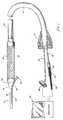
- Fig. 1 is a perspective view of the video equipped instrument having a needle probe according to one embodiment of this invention.
- Fig. 2 is a sectional elevation of the probe and housing portions of the embodiment of Fig. 1.
- Fig. 3 is a sectional view along the lines 3-3 of Fig. 2.
- With reference initially to Fig. 1 of the drawing, an
instrument 10 embodying this invention is formed of a generally cylindrical barrel-typemain housing 12 having a tapered or conicaldistal end 14 onto which anelongated probe 16 is affixed. The probe comprises a cylindrical sleeve ortube 18 of surgical steel. Aguide tube 20, which is a surgical steel tube of smaller diameter, is annexed to it, with its distal end coterminous with the forward or distal end of theprobe sleeve 18. - As better shown in Figs. 2 and 3, the
probe 16 has aglass end cap 22 that hermetically seals the distal end of thesleeve 18. Contained within thesleeve 18 is a self-focusingrod lens 24 that comprises amain rod 26 with anobjective lens 28 formed at its distal end, and with anend glass 30 situated in advance of thelens 28. A fiberoptic bundle 32 enters thesleeve 18 from within thehousing 12, and fans out to surround therod lens 24. This fiberoptic bundle 32 carries light to the forward or distal end of the sleeve for illuminating the interior surfaces of the eye tissue being examined. Sealing means 34, such as epoxy or the like, seals the proximal end of thesleeve 18 to the entrance at the tapereddistal end 14 of thehousing 12. - The
rod lens 24 operates on the principle that its index of refraction N is greatest at the axis, and decreases in proportion to the square of the distance from the axis, so as to be smallest at the edges. Themain rod 26 serves as a relay lens and carries an image formed at its distal end back to the end surface at its proximal end. Theobjective lens 28 acts as a fixed-focus converging lens. In this case, thelens 28 has a viewing angle of between about fifty and sixty degrees. The optical depth of view is between two and twelve millimeters (fixed focus) considered in a saline solution, i.e. a clear fluid isotonic with and having about the same index of refraction as human body fluids such as the aqueous humor of the eye. - Within the
main housing 12 is situated animager assembly 36, which has its optical axis aligned along the optical axis of therod lens 24. The assembly comprises atubular enclosure 38 having afront wall 40 which sealably receives theproximal end 42 of therod lens 24. Epoxy or a similar sealing means 44 hermetically seals therod lens 24 at the entrance to thewall 40.Support rings 46 support thetubular enclosure 48 within thehousing 12 and provide a passageway for the fiberoptic bundle 32. Anepoxy seal 48 hermetically seals the outer sheath of the fiberoptic bundle 32 at the passages through thesupport rings 46. - About midway within the
tubular enclosure 38 are focusingoptics 50, which are aligned along the optical axis of therod lens 24 so as to form an image on asolid state imager 52. The latter is disposed on a printedcircuit board 54 at the proximal end of theenclosure 38. Anepoxy sealing block 56 seals the proximal end of theenclosure 38 and also encapsulates lines and wires that emanate from the proximal side of the printedcircuit board 54. Thesolid state imager 52 is, for example, a CCD-type integrated circuit having an active area of about 2.5 mm square, i.e. 192 by 165 pixels. An infrared filter may be disposed between therod lens 24 and the focusingoptics 50 of theimager assembly 36. - The
tubular enclosure 38 defines aninterior space 58 which is preferably nitrogen filled, so as to preclude any problems from condensation or from the presence of possibly corrosive gases. Likewise, the sealedprobe 16 and distal part of thehousing 12 define a sealedinterior space 60 which permits theprobe 16 to be sterilized. - Returning now to Fig. 1, at the proximal end of the
housing 12 there is connected a flexible sheath orconduit 62 or for example about nine millimeters in diameter by about one hundred eighty centimeters in length. In this conduit is containedvideo conductor bundle 64 for carrying a video signal from theCCD imager 52 and also containing conductors for providing power, timing signals, and other ancillary signals to theCCD imager 52. Thefiber optic cable 32 passes through the housing and also through theconduit 62. Thevideo conductor bundle 64 terminates at its proximal end to a plug-inconnector 66 for coupling to a video processor anddisplay unit 69. The proximal end of theoptical fiber bundle 32 is highly polished and is contained in aconnector ferrule 68 of about one mm equivalent diameter. Asoft shrink tube 70 provides strain relief as between theferrule 68 and asheath 72 of thebundle 32. Theferrule 68 inserts into a corresponding fitting of an appropriate light source contained within the video processor and display unit. - An
end connector 74 of any standard configuration can be employed for mechanically connecting the proximal end of thesheath 62 to the equipment that contains the viewing apparatus. - The
proximal section 76 of theguide tube 20 curves out about thirty degrees from the axis of thehousing 12 and to the side, i.e., about ninety degrees from the vertical orientation. A flaredentrance end 78 facilitates insertion of a fine-wire type of surgical instrument into theinsertion tube 20. - A thumb-
depression 80 on the top of thedistal end wall 14 of thehousing 12 serves as an index for maintaining the proper vertical alignment of theCCD imager 52. - The probe sleeve of this embodiment has a length of thirty three millimeters and a diameter of about two millimeters or less in diameter. The
main housing 12 is about nine millimeters in diameter and seventy-five millimeters in length. Therod lens 24 has a pupil size of 0.24 mm and its the field of view constitutes about a fifty-five degree circle within an 0.1 by 0.1 inch square. - The
guide tube 20, or channel which is optional, is preferably of about 0.8 mm outside diameter, and is soldered to thestainless steel sleeve 18. With the device of this invention, a medical practitioner can perform delicate microsurgery on the interior of the eye wherein the only entrance wound would be the surgical incision of about two to three mm in length. The associated video display device provides an enlarged, erect, full color image of the tissues being examined. A surgical instrument can be guided accurately to an exact location within the eye.
Claims (3)
Applications Claiming Priority (2)
| Application Number | Priority Date | Filing Date | Title |
|---|---|---|---|
| US119707 | 1987-11-12 | ||
| US07/119,707US4854302A (en) | 1987-11-12 | 1987-11-12 | Video equipped endoscope with needle probe |
Publications (2)
| Publication Number | Publication Date |
|---|---|
| EP0316244A1 EP0316244A1 (en) | 1989-05-17 |
| EP0316244B1true EP0316244B1 (en) | 1992-01-29 |
Family
ID=22385901
Family Applications (1)
| Application Number | Title | Priority Date | Filing Date |
|---|---|---|---|
| EP88420374AExpired - LifetimeEP0316244B1 (en) | 1987-11-12 | 1988-11-08 | Video equipped endoscope with needle probe |
Country Status (4)
| Country | Link |
|---|---|
| US (1) | US4854302A (en) |
| EP (1) | EP0316244B1 (en) |
| JP (1) | JPH01155826A (en) |
| DE (1) | DE3868233D1 (en) |
Cited By (2)
| Publication number | Priority date | Publication date | Assignee | Title |
|---|---|---|---|---|
| US7942814B2 (en) | 2001-10-19 | 2011-05-17 | Visionscope Technologies Llc | Miniature endoscope with imaging fiber system |
| US8038602B2 (en) | 2001-10-19 | 2011-10-18 | Visionscope Llc | Portable imaging system employing a miniature endoscope |
Families Citing this family (81)
| Publication number | Priority date | Publication date | Assignee | Title |
|---|---|---|---|---|
| US4877016A (en)* | 1988-07-29 | 1989-10-31 | Kantor Edward A | Video endoscopic microscope |
| US4994910A (en)* | 1989-07-06 | 1991-02-19 | Acuimage Corporation | Modular endoscopic apparatus with probe |
| DE3943712C2 (en)* | 1989-08-28 | 1995-09-21 | Storz Karl Gmbh & Co | Endoscope with a video camera |
| US4969450A (en)* | 1990-01-25 | 1990-11-13 | Smith & Nephew Dyonics, Inc. | Videoarthroscope with one-handed control |
| US5025778A (en)* | 1990-03-26 | 1991-06-25 | Opielab, Inc. | Endoscope with potential channels and method of using the same |
| US5178131A (en)* | 1991-04-30 | 1993-01-12 | Upsher Laryngoscope Corporation | Waterproofed laryngoscope handle |
| US5188094A (en)* | 1991-09-30 | 1993-02-23 | Adair Edwin Lloyd | Heat sterilizable electronic video endoscope |
| US6461296B1 (en)* | 1998-06-26 | 2002-10-08 | 2000 Injectx, Inc. | Method and apparatus for delivery of genes, enzymes and biological agents to tissue cells |
| US5274500A (en)* | 1992-07-23 | 1993-12-28 | Kansas City Medical, Inc. | Video camera drape with lens |
| US5402768A (en)* | 1992-09-01 | 1995-04-04 | Adair; Edwin L. | Endoscope with reusable core and disposable sheath with passageways |
| US5416634A (en)* | 1992-09-11 | 1995-05-16 | United States Surgical Corporation | Optical viewing device |
| WO1994009694A1 (en)* | 1992-10-28 | 1994-05-11 | Arsenault, Dennis, J. | Electronic endoscope |
| US5419310A (en)* | 1992-11-03 | 1995-05-30 | Vision Sciences, Inc. | Partially inflated protective endoscope sheath |
| US5423312A (en)* | 1992-12-18 | 1995-06-13 | Schott Fiber Optics, Inc. | Rigid endoscope having modified high refractive index tunnel rod for image transmission and method of manufacture thereof |
| US5349941A (en)* | 1993-03-26 | 1994-09-27 | Oktas | Cleanable endoscope |
| US5817015A (en)* | 1993-06-22 | 1998-10-06 | Adair; Edwin L. | Endoscope with reusable core and disposable sheath with passageways |
| US5487661A (en)* | 1993-10-08 | 1996-01-30 | Dentsply International, Inc. | Portable dental camera and system |
| US5443057A (en)* | 1993-10-12 | 1995-08-22 | International Bioview, Inc. | Sterilizable endoscope and method for constructing the same |
| US5702344A (en)* | 1995-05-30 | 1997-12-30 | University Of Washington | Safe endoscopic accessory |
| US5797836A (en)* | 1995-06-07 | 1998-08-25 | Smith & Nephew, Inc. | Endoscope with relative rotation and axial motion between an optical element and an imaging device |
| US5814038A (en) | 1995-06-07 | 1998-09-29 | Sri International | Surgical manipulator for a telerobotic system |
| US5621830A (en)* | 1995-06-07 | 1997-04-15 | Smith & Nephew Dyonics Inc. | Rotatable fiber optic joint |
| US5634881A (en)* | 1995-10-20 | 1997-06-03 | United States Surgical Corporation | Laparoscope |
| US5885214A (en)* | 1996-02-13 | 1999-03-23 | Welch Allyn, Inc. | Integrated video diagnostic center |
| US20030073908A1 (en)* | 1996-04-26 | 2003-04-17 | 2000 Injectx, Inc. | Method and apparatus for delivery of genes, enzymes and biological agents to tissue cells |
| DE19717977A1 (en)* | 1997-04-23 | 1998-05-28 | Rainer Prof Dr Dr Schmelzeisen | Lining=up fixture device used to treat jaw or face fractures |
| US5895870A (en)* | 1997-05-27 | 1999-04-20 | Framatome Technologies, Inc. | Tube sheet retractable probe |
| US6185443B1 (en) | 1997-09-29 | 2001-02-06 | Boston Scientific Corporation | Visible display for an interventional device |
| US6043839A (en) | 1997-10-06 | 2000-03-28 | Adair; Edwin L. | Reduced area imaging devices |
| US5929901A (en)* | 1997-10-06 | 1999-07-27 | Adair; Edwin L. | Reduced area imaging devices incorporated within surgical instruments |
| US6310642B1 (en) | 1997-11-24 | 2001-10-30 | Micro-Medical Devices, Inc. | Reduced area imaging devices incorporated within surgical instruments |
| US7030904B2 (en)* | 1997-10-06 | 2006-04-18 | Micro-Medical Devices, Inc. | Reduced area imaging device incorporated within wireless endoscopic devices |
| US20110034769A1 (en) | 1997-10-06 | 2011-02-10 | Micro-Imaging Solutions Llc | Reduced area imaging device incorporated within wireless endoscopic devices |
| US6452626B1 (en) | 1997-10-06 | 2002-09-17 | Edwin L. Adair | Communication devices incorporating reduced area imaging devices |
| US6424369B1 (en) | 1997-10-06 | 2002-07-23 | Edwin L. Adair | Hand-held computers incorporating reduced area imaging devices |
| US5986693A (en)* | 1997-10-06 | 1999-11-16 | Adair; Edwin L. | Reduced area imaging devices incorporated within surgical instruments |
| US7002621B2 (en)* | 1997-10-06 | 2006-02-21 | Adair Edwin L | Communication devices incorporating reduced area imaging devices |
| US6982742B2 (en)* | 1997-10-06 | 2006-01-03 | Adair Edwin L | Hand-held computers incorporating reduced area imaging devices |
| US6982740B2 (en)* | 1997-11-24 | 2006-01-03 | Micro-Medical Devices, Inc. | Reduced area imaging devices utilizing selected charge integration periods |
| US5957927A (en)* | 1998-02-24 | 1999-09-28 | Synthes (Usa) | Bone fixation device introducer |
| EP1028649A4 (en)* | 1998-09-09 | 2004-10-20 | Dennis Q Mcmanus | Microscopy method and apparatus |
| US20020087047A1 (en)* | 1999-09-13 | 2002-07-04 | Visionscope, Inc. | Miniature endoscope system |
| US8317689B1 (en) | 1999-09-13 | 2012-11-27 | Visionscope Technologies Llc | Miniature endoscope system |
| DE60043392D1 (en)* | 1999-09-13 | 2010-01-07 | Visionscope Technologies Llc | MINIATURE ENDOSCOPE ARRANGEMENT |
| JP2003514616A (en)* | 1999-11-24 | 2003-04-22 | グリースハーバー ウント コンパニー アーゲー シャフハウゼン | Apparatus for improving the outflow of aqueous humor in a living eye |
| US6757413B1 (en) | 2000-02-23 | 2004-06-29 | American Telecare, Inc. | Low-cost medical image transfer and control system and method |
| US10595710B2 (en)* | 2001-10-19 | 2020-03-24 | Visionscope Technologies Llc | Portable imaging system employing a miniature endoscope |
| US20070167681A1 (en) | 2001-10-19 | 2007-07-19 | Gill Thomas J | Portable imaging system employing a miniature endoscope |
| US8423110B2 (en)* | 2002-01-09 | 2013-04-16 | Boston Scientific Scimed, Inc. | Imaging device and related methods |
| DE10222505A1 (en)* | 2002-05-22 | 2003-12-11 | Schoelly Fiberoptic Gmbh | microendoscope |
| EP2193821A1 (en)* | 2004-04-29 | 2010-06-09 | iScience Interventional Corporation | Apparatus for ocular treatment |
| WO2005107664A2 (en)* | 2004-04-29 | 2005-11-17 | Iscience Interventional Corporation | Apparatus and method for surgical enhancement of aqueous humor drainage |
| US20100173866A1 (en)* | 2004-04-29 | 2010-07-08 | Iscience Interventional Corporation | Apparatus and method for ocular treatment |
| US7611060B2 (en) | 2005-03-11 | 2009-11-03 | Hand Held Products, Inc. | System and method to automatically focus an image reader |
| US7568628B2 (en) | 2005-03-11 | 2009-08-04 | Hand Held Products, Inc. | Bar code reading device with global electronic shutter control |
| US7780089B2 (en) | 2005-06-03 | 2010-08-24 | Hand Held Products, Inc. | Digital picture taking optical reader having hybrid monochrome and color image sensor array |
| US7770799B2 (en) | 2005-06-03 | 2010-08-10 | Hand Held Products, Inc. | Optical reader having reduced specular reflection read failures |
| US7583876B2 (en)* | 2006-06-30 | 2009-09-01 | Schott Corporation | Illuminable image-conducting optical assembly including light-conductive optics housing for creating an illuminating halo |
| US8425473B2 (en)* | 2009-01-23 | 2013-04-23 | Iscience Interventional Corporation | Subretinal access device |
| US20100191177A1 (en)* | 2009-01-23 | 2010-07-29 | Iscience Interventional Corporation | Device for aspirating fluids |
| US20110080500A1 (en)* | 2009-10-05 | 2011-04-07 | Hand Held Products, Inc. | Imaging terminal, imaging sensor having multiple reset and/or multiple read mode and methods for operating the same |
| US8786210B2 (en) | 2010-06-30 | 2014-07-22 | Welch Allyn, Inc. | Drive circuit for light emitting diode |
| CN102253057B (en)* | 2011-04-13 | 2013-06-05 | 中国科学院深圳先进技术研究院 | Endoscope system and measurement method using endoscope system |
| US8629926B2 (en) | 2011-11-04 | 2014-01-14 | Honeywell International, Inc. | Imaging apparatus comprising image sensor array having shared global shutter circuitry |
| FR2994727A1 (en)* | 2012-08-24 | 2014-02-28 | Commissariat Energie Atomique | DUAL OPTICAL MULTIFIBRE FLUX LIGHTING DEVICE AND ASSOCIATED PEROPERATIVE PROBE |
| DE102014107572B4 (en)* | 2014-05-28 | 2022-10-20 | Karl Storz Se & Co. Kg | Endoscope lens and endoscope |
| WO2016137838A1 (en)* | 2015-02-23 | 2016-09-01 | Xiaolong Ouyang | Handheld surgical endoscope |
| US10869592B2 (en) | 2015-02-23 | 2020-12-22 | Uroviu Corp. | Handheld surgical endoscope |
| JP2018538069A (en)* | 2015-12-11 | 2018-12-27 | ビーバー−ビジテック インターナショナル インコーポレイテッド | Laser video endoscope |
| US10463245B2 (en) | 2015-12-21 | 2019-11-05 | Snug Harbor Orthopedics, LLC | Method of using cannula for surgical procedure |
| JP7146733B2 (en) | 2016-07-18 | 2022-10-04 | ビオプティックス・インコーポレイテッド | Oxygen measurement device with laparoscopic dilation |
| US9984268B2 (en) | 2016-08-31 | 2018-05-29 | Vium, Inc. | Code for animal ID marking |
| DE102016216443A1 (en)* | 2016-08-31 | 2018-03-01 | Schott Ag | Illumination system with heterogeneous fiber arrangement |
| US11832797B2 (en) | 2016-09-25 | 2023-12-05 | Micronvision Corp. | Endoscopic fluorescence imaging |
| US11684248B2 (en) | 2017-09-25 | 2023-06-27 | Micronvision Corp. | Endoscopy/stereo colposcopy medical instrument |
| JP6906987B2 (en)* | 2017-03-10 | 2021-07-21 | ソニー・オリンパスメディカルソリューションズ株式会社 | Camera head for endoscope |
| DE102017108029B3 (en)* | 2017-04-13 | 2018-05-30 | Karl Storz Se & Co. Kg | endoscope |
| US11771304B1 (en) | 2020-11-12 | 2023-10-03 | Micronvision Corp. | Minimally invasive endoscope |
| US12268358B2 (en) | 2019-12-05 | 2025-04-08 | Uroviu Corp. | Portable endoscope with side-mountable disposable portion |
| US11980342B2 (en) | 2020-11-12 | 2024-05-14 | Micronvision Corp. | Minimally invasive endoscope |
| EP4003138A4 (en) | 2019-07-25 | 2023-08-30 | Uroviu Corp. | DISPOSABLE ENDOSCOPY NEEDLE WITH INTEGRATED GRIPPER |
Citations (1)
| Publication number | Priority date | Publication date | Assignee | Title |
|---|---|---|---|---|
| US3257902A (en)* | 1959-07-16 | 1966-06-28 | Watson W & Sons Ltd | Optical system having cylindrical rod-like lenses |
Family Cites Families (16)
| Publication number | Priority date | Publication date | Assignee | Title |
|---|---|---|---|---|
| GB1268855A (en)* | 1968-08-24 | 1972-03-29 | Nippon Selfoc Co Ltd | Optical image transmitting apparatus |
| US4074306A (en)* | 1975-07-28 | 1978-02-14 | Olympus Optical Co., Ltd. | Endoscope utilizing color television and fiber optics techniques |
| US4414962A (en)* | 1977-06-15 | 1983-11-15 | Carson Robert W | Operating arthroscope |
| US4281929A (en)* | 1979-05-17 | 1981-08-04 | The United States Of America As Represented By The United States Department Of Energy | Small diameter, deep bore optical inspection system |
| JPS57129407A (en)* | 1981-02-03 | 1982-08-11 | Olympus Optical Co Ltd | Hard endoscope |
| US4491865A (en)* | 1982-09-29 | 1985-01-01 | Welch Allyn, Inc. | Image sensor assembly |
| US4764334A (en)* | 1983-10-17 | 1988-08-16 | Westinghouse Electric Corp. | Visual inspection system for radioactive fuel assemblies using fiberoptics |
| US4600940A (en)* | 1984-02-07 | 1986-07-15 | Circon Corporation | Video camera for use with an endoscope and method for making same |
| US4539976A (en)* | 1984-02-08 | 1985-09-10 | Sharpe Jewett M | Endoscopic surgical instrument |
| JPS60243625A (en)* | 1984-05-18 | 1985-12-03 | Fuji Photo Optical Co Ltd | Connecting system of endoscope |
| JPS6115117A (en)* | 1984-07-02 | 1986-01-23 | Asahi Optical Co Ltd | TV endoscope |
| US4643546A (en)* | 1984-07-09 | 1987-02-17 | Welch Allyn, Inc. | Ophthalmoscope with automatic lens shifting mechanism |
| US4607622A (en)* | 1985-04-11 | 1986-08-26 | Charles D. Fritch | Fiber optic ocular endoscope |
| EP0243455A4 (en)* | 1985-10-11 | 1989-01-26 | Microvasive Inc | Fiber-optic image-carrying device. |
| JPS6349125A (en)* | 1986-08-16 | 1988-03-01 | 奥津 一郎 | Guide pipe for endoscope |
| US4756304A (en)* | 1986-10-08 | 1988-07-12 | Watanabe Robert S | Arthroscopic video camera system |
- 1987
- 1987-11-12USUS07/119,707patent/US4854302A/ennot_activeExpired - Fee Related
- 1988
- 1988-11-08EPEP88420374Apatent/EP0316244B1/ennot_activeExpired - Lifetime
- 1988-11-08DEDE8888420374Tpatent/DE3868233D1/ennot_activeExpired - Lifetime
- 1988-11-11JPJP63285599Apatent/JPH01155826A/enactivePending
Patent Citations (1)
| Publication number | Priority date | Publication date | Assignee | Title |
|---|---|---|---|---|
| US3257902A (en)* | 1959-07-16 | 1966-06-28 | Watson W & Sons Ltd | Optical system having cylindrical rod-like lenses |
Non-Patent Citations (1)
| Title |
|---|
| KARL STORZ BROCHURE: HOPKINS TELESCOPES* |
Cited By (2)
| Publication number | Priority date | Publication date | Assignee | Title |
|---|---|---|---|---|
| US7942814B2 (en) | 2001-10-19 | 2011-05-17 | Visionscope Technologies Llc | Miniature endoscope with imaging fiber system |
| US8038602B2 (en) | 2001-10-19 | 2011-10-18 | Visionscope Llc | Portable imaging system employing a miniature endoscope |
Also Published As
| Publication number | Publication date |
|---|---|
| JPH01155826A (en) | 1989-06-19 |
| DE3868233D1 (en) | 1992-03-12 |
| EP0316244A1 (en) | 1989-05-17 |
| US4854302A (en) | 1989-08-08 |
Similar Documents
| Publication | Publication Date | Title |
|---|---|---|
| EP0316244B1 (en) | Video equipped endoscope with needle probe | |
| CA1206250A (en) | Ultrasonic endoscope having elongated array mounted in manner allowing it to remain flexible | |
| US5817015A (en) | Endoscope with reusable core and disposable sheath with passageways | |
| KR100630624B1 (en) | Video rectal endoscope | |
| US6398724B1 (en) | Focusable optical instrument with a sealed optical system having no internal optical moving parts | |
| US5198894A (en) | Drape for endoscope | |
| EP1478264B1 (en) | Miniature endoscope with imaging fiber system | |
| US5351678A (en) | Endoscope scope assembly for full hemisphere view | |
| US5329936A (en) | Portable arthroscope with periscope optics | |
| US4782819A (en) | Optical catheter | |
| US5188093A (en) | Portable arthroscope with periscope optics | |
| US5630782A (en) | Sterilizable endoscope with separable auxiliary assembly | |
| US5124797A (en) | Modular view lens attachment for micro video imaging camera | |
| CA2034394C (en) | Dental instrument including laser device and electronic video dental camera | |
| US4651201A (en) | Stereoscopic endoscope arrangement | |
| JPH0221041Y2 (en) | ||
| US5688224A (en) | Medical visualization device | |
| US5323767A (en) | Portable arthroscope with periscope optics | |
| JPH04309325A (en) | Portable arthroscope with disposable probe | |
| EP0549097A1 (en) | Portable arthroscope with periscope optics | |
| US4994910A (en) | Modular endoscopic apparatus with probe | |
| Allan | Fibre Optics in Medicine | |
| GB2339539A (en) | Medical viewing device |
Legal Events
| Date | Code | Title | Description |
|---|---|---|---|
| PUAI | Public reference made under article 153(3) epc to a published international application that has entered the european phase | Free format text:ORIGINAL CODE: 0009012 | |
| AK | Designated contracting states | Kind code of ref document:A1 Designated state(s):DE FR GB IT | |
| 17P | Request for examination filed | Effective date:19891110 | |
| 17Q | First examination report despatched | Effective date:19900109 | |
| GRAA | (expected) grant | Free format text:ORIGINAL CODE: 0009210 | |
| AK | Designated contracting states | Kind code of ref document:B1 Designated state(s):DE FR GB IT | |
| ITF | It: translation for a ep patent filed | ||
| ET | Fr: translation filed | ||
| REF | Corresponds to: | Ref document number:3868233 Country of ref document:DE Date of ref document:19920312 | |
| PLBE | No opposition filed within time limit | Free format text:ORIGINAL CODE: 0009261 | |
| 26N | No opposition filed | ||
| PGFP | Annual fee paid to national office [announced via postgrant information from national office to epo] | Ref country code:GB Payment date:19931119 Year of fee payment:6 | |
| PGFP | Annual fee paid to national office [announced via postgrant information from national office to epo] | Ref country code:FR Payment date:19931125 Year of fee payment:6 | |
| PGFP | Annual fee paid to national office [announced via postgrant information from national office to epo] | Ref country code:DE Payment date:19931223 Year of fee payment:6 | |
| PG25 | Lapsed in a contracting state [announced via postgrant information from national office to epo] | Ref country code:GB Effective date:19941108 | |
| GBPC | Gb: european patent ceased through non-payment of renewal fee | Effective date:19941108 | |
| PG25 | Lapsed in a contracting state [announced via postgrant information from national office to epo] | Ref country code:FR Effective date:19950731 | |
| PG25 | Lapsed in a contracting state [announced via postgrant information from national office to epo] | Ref country code:DE Effective date:19950801 | |
| REG | Reference to a national code | Ref country code:FR Ref legal event code:ST | |
| PG25 | Lapsed in a contracting state [announced via postgrant information from national office to epo] | Ref country code:IT Free format text:LAPSE BECAUSE OF NON-PAYMENT OF DUE FEES Effective date:20051108 |