EP0313422B1 - Static tripping device for a circuit breaker in a cast case - Google Patents
Static tripping device for a circuit breaker in a cast caseDownload PDFInfo
- Publication number
- EP0313422B1 EP0313422B1EP88402357AEP88402357AEP0313422B1EP 0313422 B1EP0313422 B1EP 0313422B1EP 88402357 AEP88402357 AEP 88402357AEP 88402357 AEP88402357 AEP 88402357AEP 0313422 B1EP0313422 B1EP 0313422B1
- Authority
- EP
- European Patent Office
- Prior art keywords
- circuit breaker
- arc
- tripping
- contacts
- processing unit
- Prior art date
- Legal status (The legal status is an assumption and is not a legal conclusion. Google has not performed a legal analysis and makes no representation as to the accuracy of the status listed.)
- Expired - Lifetime
Links
Images
Classifications
- H—ELECTRICITY
- H02—GENERATION; CONVERSION OR DISTRIBUTION OF ELECTRIC POWER
- H02H—EMERGENCY PROTECTIVE CIRCUIT ARRANGEMENTS
- H02H1/00—Details of emergency protective circuit arrangements
- H02H1/0007—Details of emergency protective circuit arrangements concerning the detecting means
- H02H1/0015—Using arc detectors
- H02H1/0023—Using arc detectors sensing non electrical parameters, e.g. by optical, pneumatic, thermal or sonic sensors
- H—ELECTRICITY
- H02—GENERATION; CONVERSION OR DISTRIBUTION OF ELECTRIC POWER
- H02H—EMERGENCY PROTECTIVE CIRCUIT ARRANGEMENTS
- H02H3/00—Emergency protective circuit arrangements for automatic disconnection directly responsive to an undesired change from normal electric working condition with or without subsequent reconnection ; integrated protection
- H02H3/08—Emergency protective circuit arrangements for automatic disconnection directly responsive to an undesired change from normal electric working condition with or without subsequent reconnection ; integrated protection responsive to excess current
- H02H3/093—Emergency protective circuit arrangements for automatic disconnection directly responsive to an undesired change from normal electric working condition with or without subsequent reconnection ; integrated protection responsive to excess current with timing means
- H02H3/0935—Emergency protective circuit arrangements for automatic disconnection directly responsive to an undesired change from normal electric working condition with or without subsequent reconnection ; integrated protection responsive to excess current with timing means the timing being determined by numerical means
- H—ELECTRICITY
- H01—ELECTRIC ELEMENTS
- H01H—ELECTRIC SWITCHES; RELAYS; SELECTORS; EMERGENCY PROTECTIVE DEVICES
- H01H71/00—Details of the protective switches or relays covered by groups H01H73/00 - H01H83/00
- H01H71/10—Operating or release mechanisms
- H01H71/12—Automatic release mechanisms with or without manual release
- H01H71/24—Electromagnetic mechanisms
- H01H71/2418—Electromagnetic mechanisms combined with an electrodynamic current limiting mechanism
- H01H2071/2427—Electromagnetic mechanisms combined with an electrodynamic current limiting mechanism with blow-off movement tripping mechanism, e.g. electrodynamic effect on contacts trips the traditional trip device before it can unlatch the spring mechanism by itself
Definitions
- the inventionrelates to a static trip device of an electric circuit breaker with a molded case having, by pole, a pair of contacts, elastically biased in contact in the closed position of the circuit breaker and capable of separating under the action of an automatic control mechanism.
- on faultcomprising sensors which generate fault signals, a function of the currents flowing through the conductors protected by the circuit breaker, and a processing assembly to which said fault signals are applied to develop a tripping order for the circuit breaker, when exceeding a predetermined threshold, said order being timed as a function of the value of the fault signals.
- the contacts of an electric circuit breakermust open virtually to avoid any intermediate position of repulsion of the contacts, the latter being nevertheless insufficiently separated for the extinction of the arc drawn between the contacts.
- the persistence of the arc between the partially open contactscauses overheating and destruction of the circuit breaker.
- the repulsion of the contactsoccurs under the effect of electrodynamic forces when the current exceeds a predetermined threshold of repulsion, this threshold depending on the configuration of the current in the circuit breaker as well as on the adjustment characteristics of the pole.
- the tripping threshold on faultis generally fixed at a value lower than that of the repulsion threshold. It is difficult and costly to make circuit breakers having perfectly defined repulsion and tripping thresholds and to overcome these inaccuracies, it is frequent to choose a tripping threshold 20 to 50% lower than the repulsion threshold, which results in a significant loss of selectivity.
- the present inventionaims to allow the production of a trigger whose trigger threshold and repulsion threshold are combined.
- Another object of the inventionis a trip unit ensuring instantaneous tripping when the circuit breaker closes on a fault.
- the trip deviceis characterized in that an arc detector is associated with each pair of contacts to detect the light emitted by the arc drawn during a separation of the contacts, the arc signals emitted by said contacts arc detectors being applied to said processing assembly to cause instantaneous triggering when simultaneously the fault signals exceed said predetermined threshold.
- any separation of the contactscauses the formation of a spark or an arc emitting a light easily detectable by optical sensors such as photoelectric components which are preferably arranged away from the arc zone and connected to it by light conductors such as optical fibers.
- optical sensorssuch as photoelectric components which are preferably arranged away from the arc zone and connected to it by light conductors such as optical fibers.
- the detection of the presence of an arc and the detection of a fault currentdo not require any particular precision, the light emitted by the arc being overabundant and the difference between a current likely to cause the repulsion of the contacts and the rated current of the circuit breaker being very high.
- the electrodynamic repulsioncan occur on a single pair of circuit breaker contacts and it is important to detect this repulsion by associating with each pair of circuit breaker contacts, an arc detector.
- optical fiberit is possible to collect the light emitted by any one of the poles of the circuit breaker by passing this fiber through the different arcing compartments near the pairs of contacts, but it is conceivable to having a detector at a location in the molded housing making it possible to see, through holes made in the internal partitions of the molded housing, the light emitted by any one of the pairs of contacts.
- An optical fiber transmitting light to the processing unitcan be associated with each pair of contacts.
- the trigger on contact repulsionis advantageously associated, or in addition ensures the usual long delay and short delay tripping of protection on overload or on fault of an amplitude lower than the repulsion threshold of the circuit breaker.
- the static trip devicecomprises analog and / or digital processing circuits, the instantaneous trip circuit on contact repulsion being advantageously analog in order to have a very reduced response time.
- the subordination of instantaneous tripping to the simultaneous presence of an arc signal and a fault signalcan be achieved by an appropriate means, in particular by an AND circuit, receiving on its inputs the two arc and fault signals .
- the static release according to the inventionalso ensures the instant protection when closing the circuit breaker on fault. In this case it is important to cause the immediate opening of the circuit breaker, independently of the short delay and long delay tripping circuits which provide a time delay compatible with tripping selectivity. Closing on fault automatically causes an arc on the contacts which is detected by the arc detectors as well as an overcurrent signaled by a fault signal, causing the opening of the circuit breaker.
- the device according to the inventionadvantageously replaces the timed contacts which inhibit the instantaneous trip device after a certain time.
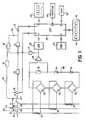
- an electrical distribution network with 3 conductors R, S, T, for supplying a loadcomprises a circuit breaker 10 capable of interrupting the circuit in the open position.
- the mechanism 12 of the circuit breaker 10is controlled by a polarized relay 14 for controlling the tripping of the circuit breaker in the event of an overload or a short circuit.
- An auxiliary contact 16, associated with the main contacts 17R, 17S, 17T, of the circuit breaker 10indicates the position of these main contacts 17R, 17S, 17T.
- Each conductor R, S, Tis associated with a current transformer 18 which delivers a signal proportional to the current flowing through the associated conductor, this signal being applied to a full-wave rectifier bridge 20.
- the outputs of the 3 rectifier bridges 20are connected in series in a circuit comprising a resistor 22, a zener diode 24 and a diode 26 to cause the terminals of the resistor 22 to display a voltage signal proportional to the maximum value of the current flowing through the conductors R, S, T and across the diode 24, a supply voltage of the electronic circuits.
- the voltage signalis applied to the input of the amplifier 28, the output of which is connected to an analog-digital converter 30.
- the output of the analog-digital converter 30is connected to an input output 1 of a microprocessor 32.
- the microprocessor 32further comprises a output 2 connected to the polarized relay 14, an input 3 receiving the signals from a clock 34, an input 4 connected to a keyboard 36 with key 44, an input 6 connected to a ROM read-only memory 38, an input / output 5 connected to a non-volatile NOVRAM memory 40, an output 7 connected to a display device 42 and an input 8 connected to the auxiliary contact 16.
- the trip deviceprovides the protection function, in particular the long delay trigger and / or the short delay trigger respectively during an overload and a fault appearing in the circuit of conductors R, S, T.
- the signal digital representative of the maximum value of the current in the conductors R, S, Tis applied to input 1 of the microprocessor 32 and compared with threshold values stored in a memory to detect any exceedance of these thresholds and generate an order of timed or instantaneous tripping, which is transmitted to relay 14 to cause the opening of the circuit breaker 10.
- the tripping devicecan of course perform other functions, in particular earth protection.
- a trigger of the kind mentionedis well known to specialists and is for example described in European patent application No. 87401714.8 of 20.7.87 published under the number EP-A-258 090, to which reference will advantageously be made.
- the inventioncan be used in any static trigger and is in no way limited to the trigger of the type described above.
- the current detection meansmay include current sensors supplying analog signals representative of the derivative of the current di / dt and the output of which is connected to integrating circuits, the output signals of the integrator circuits being transmitted to the microprocessor via an analog-digital converter.
- the static releasecan also be of the analog type.
- the circuit breaker 10comprises an envelope of the molded case type inside of which the main contacts 17R, 17S, 17T, of the three poles of the circuit breaker are arranged.
- the three poles R, S, Tare separated by walls defining internal compartments of the molded housing and each pole is associated with an arc detector 46R, 46S, 46T arranged near the main contacts 17R, 17S, 17T.
- the light collected by the arc detectors 46R, 46S, 46Tis transmitted by an optical fiber 48 to a photoelectric component 50 which emits an electrical signal proportional to the light received, this electrical signal being applied to an input of an AND circuit. 52.
- the other gate of the AND circuit 52is connected to a threshold circuit 54 connected to the output of the amplifier 28.
- the output of the AND circuit 52is connected via a diode 56 to the polarized relay 14.
- a diode 58is inserted in the link between the output 2 of the microprocessor 32 and the polarized relay 14 to avoid any interference between the trigger signals applied to the polarized relay 14, respectively by the microprocessor 32 and by the instantaneous triggering circuit of repulsion of 'bow.
- the static trip device according to the inventionoperates as follows:
- the microprocessor 32causes the possibly timed tripping of the circuit breaker 10 in the usual manner.
- the separation of the contacts 17R, 17S, 17Tcauses the emission of light, detected by the arc detectors 46R, 46S, 46T, and transmitted by the optical fiber 48 to the photoelectric component 50 which applies a signal to the AND circuit 52.
- This AND circuit 52which receives a fault signal at its other input sends to the polarized relay 14 a superabundant tripping order, the latter having already caused tripping of the circuit breaker 10. This additional order does not disturb the operation of the tripping device.
- the inhibition of the instantaneous tripping arc signalcan of course be carried out by different means, in particular by overload detectors independent of the sensors controlling the short delay and long delay tripping.
- the light conductorcan be a plastic optical fiber whose end close to the main contacts 17R, 17S, 17T is stripped over a short length to capture the light from the arc, the stripped end of the fiber constituting the detector. arc.
- the stripped end of the optical fiber 48 which constitutes the arc detectoris preferably arranged in a zone protected from pollution due to the arc, or this end is arranged to undergo a cleaning, for example mechanical cleaning each time operation of the circuit breaker by any appropriate means.
- the instantaneous arc detection trip device according to the inventioncan of course be used in different types of static trip devices, in particular of the analog type.
- the trip device according to the inventionalso provides instant protection during a fault closure as follows:
Landscapes
- Emergency Protection Circuit Devices (AREA)
- Driving Mechanisms And Operating Circuits Of Arc-Extinguishing High-Tension Switches (AREA)
Description
Translated fromFrenchL'invention est relative à un déclencheur statique d'un disjoncteur électrique à boîtier moulé ayant par pôle une paire de contacts, sollicités élastiquement au contact en position fermé du disjoncteur et susceptibles de se séparer sous l'action d'un mécanisme de commande automatique sur défaut, comprenant des capteurs qui engendrent des signaux de défaut, fonction des courants parcourant les conducteurs protégés par le disjoncteur, et un ensemble de traitement auquel sont appliqués lesdits signaux de défaut pour élaborer un ordre de déclenchement du disjoncteur, lors du dépassement d'un seuil prédéterminé, ledit ordre étant temporisé en fonction de la valeur des signaux de défaut.The invention relates to a static trip device of an electric circuit breaker with a molded case having, by pole, a pair of contacts, elastically biased in contact in the closed position of the circuit breaker and capable of separating under the action of an automatic control mechanism. on fault, comprising sensors which generate fault signals, a function of the currents flowing through the conductors protected by the circuit breaker, and a processing assembly to which said fault signals are applied to develop a tripping order for the circuit breaker, when exceeding a predetermined threshold, said order being timed as a function of the value of the fault signals.
Les contacts d'un disjoncteur électrique doivent s'ouvrir franchement pour éviter toute position intermédiaire de répulsion des contacts, ces derniers étant néanmoins insuffisamment séparés pour l'extinction de l'arc tiré entre les contacts. La persistance de l'arc entre les contacts partiellement ouverts provoque un échauffement et une destruction du disjoncteur. La répulsion des contacts intervient sous l'effet des forces électrodynamiques lorsque le courant dépasse un seuil prédéterminé de répulsion, ce seuil dépendant de la configuration du courant dans le disjoncteur ainsi que des caractéristiques de réglage du pôle.The contacts of an electric circuit breaker must open frankly to avoid any intermediate position of repulsion of the contacts, the latter being nevertheless insufficiently separated for the extinction of the arc drawn between the contacts. The persistence of the arc between the partially open contacts causes overheating and destruction of the circuit breaker. The repulsion of the contacts occurs under the effect of electrodynamic forces when the current exceeds a predetermined threshold of repulsion, this threshold depending on the configuration of the current in the circuit breaker as well as on the adjustment characteristics of the pole.
Pour être certain qu'un disjoncteur ne reste pas dans une position intermédiaire de répulsion des contacts, on fixe généralement le seuil de déclenchement sur défaut à une valeur inférieure à celle du seuil de répulsion. Il est difficile et coûteux de réaliser des disjoncteurs ayant des seuils de répulsion et de déclenchement parfaitement définis et pour pallier ces imprécisions, il est fréquent de choisir un seuil de déclenchement de 20 à 50 % inférieur au seuil de répulsion, ce qui se traduit par une perte de sélectivité importante.To be certain that a circuit breaker does not remain in an intermediate position of repulsion of the contacts, the tripping threshold on fault is generally fixed at a value lower than that of the repulsion threshold. It is difficult and costly to make circuit breakers having perfectly defined repulsion and tripping thresholds and to overcome these inaccuracies, it is frequent to choose a
La présente invention a pour but de permettre la réalisation d'un déclencheur dont le seuil de déclenchement et le seuil de répulsion sont confondus.The present invention aims to allow the production of a trigger whose trigger threshold and repulsion threshold are combined.
Un autre but de l'invention est un déclencheur assurant un déclenchement instantané lors d'une fermeture du disjoncteur sur un défaut.Another object of the invention is a trip unit ensuring instantaneous tripping when the circuit breaker closes on a fault.
Le déclencheur selon l'invention est caractérisé en ce qu'un détecteur d'arc est associé à chaque paire de contacts pour détecter la lumière émise par l'arc tiré lors d'une séparation des contacts, les signaux d'arc émis par lesdits détecteurs d'arc étant appliqués audit ensemble de traitement pour provoquer un déclenchement instantané lorsque simultanément les signaux de défaut dépassent ledit seuil prédéterminé.The trip device according to the invention is characterized in that an arc detector is associated with each pair of contacts to detect the light emitted by the arc drawn during a separation of the contacts, the arc signals emitted by said contacts arc detectors being applied to said processing assembly to cause instantaneous triggering when simultaneously the fault signals exceed said predetermined threshold.
Toute séparation des contacts, notamment par les forces électrodynamiques de répulsion, provoque la formation d'une étincelle ou d'un arc émettant une lumière facilement détectable par des capteurs optiques tels que des composants photoélectriques qui sont de préférence disposés à l'écart de la zone d'arc et reliés à cette dernière par des conducteurs de lumière telles que des fibres optiques. En disposant selon l'invention les capteurs ou détecteurs d'arc à l'intérieur du boîtier moulé, on s'affranchit d'une manière particulièrement simple des perturbations dues à la lumière extérieure. En assujettissant le déclenchement instantané du disjoncteur à la présence simultanée d'un signal d'arc et d'un signal de défaut, on évite les déclenchements intempestifs, dus aux arcs tirés entre les contacts lors de la fermeture ou de l'ouverture normales du disjoncteur. Il est facile de comprendre que la détection de la présence d'un arc et la détection d'un courant de défaut n'exigent pas de précision particulière, la lumière émise par l'arc étant surabondante et la différence entre un courant susceptible de provoquer la répulsion des contacts et le courant nominal du disjoncteur étant très importante. Selon la configuration du courant ou les caractéristiques du pôle, la répulsion électrodynamique peut intervenir sur une seule paire de contacts du disjoncteur et il est important de détecter cette répulsion en associant à chaque paire de contacts du disjoncteur, un détecteur d'arc. Dans la cas d'une fibre optique, il est possible de collecter la lumière émise par l'un quelconque des pôles du disjoncteur en faisant passer cette fibre dans les différents compartiments d'arc à proximité des paires de contacts, mais il est concevable de disposer un détecteur en un emplacement du boîtier moulé permettant de voir par des orifices pratiqués dans les cloisons internes du boîtier moulé, la lumière émise par l'une quelconque des paires de contacts. A chaque paire de contacts, peut être associée une fibre optique transmettant la lumière vers l'ensemble de traitement.Any separation of the contacts, in particular by the electrodynamic forces of repulsion, causes the formation of a spark or an arc emitting a light easily detectable by optical sensors such as photoelectric components which are preferably arranged away from the arc zone and connected to it by light conductors such as optical fibers. By having, according to the invention, the arc sensors or detectors inside the molded case, it is particularly simple to overcome disturbances due to outside light. By subjecting the instantaneous tripping of the circuit breaker to the simultaneous presence of an arc signal and a fault signal, inadvertent tripping is avoided, due to arcs drawn between the contacts during normal closing or opening of the circuit breaker. It is easy to understand that the detection of the presence of an arc and the detection of a fault current do not require any particular precision, the light emitted by the arc being overabundant and the difference between a current likely to cause the repulsion of the contacts and the rated current of the circuit breaker being very high. Depending on the current configuration or the characteristics of the pole, the electrodynamic repulsion can occur on a single pair of circuit breaker contacts and it is important to detect this repulsion by associating with each pair of circuit breaker contacts, an arc detector. In the case of an optical fiber, it is possible to collect the light emitted by any one of the poles of the circuit breaker by passing this fiber through the different arcing compartments near the pairs of contacts, but it is conceivable to having a detector at a location in the molded housing making it possible to see, through holes made in the internal partitions of the molded housing, the light emitted by any one of the pairs of contacts. An optical fiber transmitting light to the processing unit can be associated with each pair of contacts.
En utilisant la lumière pour détecter la répulsion des contacts, on est assuré d'éviter tout déclenchement avant la séparation des contacts sous l'effet de répulsion électrodynamique et inversement de provoquer le déclenchement instantané du disjoncteur dès la répulsion de l'une quelconque des paires de contacts du disjoncteur. Le déclencheur sur répulsion des contacts est avantageusement associé, ou assure en plus le déclenchement long retard et court retard usuel de protection sur surcharge ou sur défaut d'une amplitude inférieure au seuil de répulsion du disjoncteur.By using the light to detect the repulsion of the contacts, one is sure to avoid any tripping before the separation of the contacts under the effect of electrodynamic repulsion and conversely to cause the instantaneous tripping of the circuit breaker as soon as the repulsion of any of the pairs circuit breaker contacts. The trigger on contact repulsion is advantageously associated, or in addition ensures the usual long delay and short delay tripping of protection on overload or on fault of an amplitude lower than the repulsion threshold of the circuit breaker.
Le déclencheur statique selon l'invention comporte des circuits de traitement analogique et/ou numérique, le circuit de déclenchement instantané sur répulsion des contacts étant avantageusement analogique afin de disposer d'un temps de réponse très réduit. La subordination du déclenchement instantané à la présence simultanée d'un signal d'arc et d'un signal de défaut peut être réalisée par un moyen approprié, notamment par un circuit ET, recevant sur ses entrées les deux signaux d'arc et de défaut.The static trip device according to the invention comprises analog and / or digital processing circuits, the instantaneous trip circuit on contact repulsion being advantageously analog in order to have a very reduced response time. The subordination of instantaneous tripping to the simultaneous presence of an arc signal and a fault signal can be achieved by an appropriate means, in particular by an AND circuit, receiving on its inputs the two arc and fault signals .
Le déclencheur statique selon l'invention assure également la protection instantanée lors de la fermeture du disjoncteur sur défaut. Dans ce cas il est important de provoquer l'ouverture immédiate du disjoncteur, indépendamment des circuits de déclenchement court retard et long retard qui assurent une temporisation comptatible avec la sélectivité de déclenchement. Une fermeture sur défaut provoque automatiquement un arc sur les contacts qui est détecté par les détecteurs d'arc ainsi qu'une surintensité signalée par un signal de défaut, provoquant l'ouverture du disjoncteur. Le dispositif selon l'invention remplace avantageusement les contacts temporisés qui inhibent le déclencheur instantané après un certain temps.The static release according to the invention also ensures the instant protection when closing the circuit breaker on fault. In this case it is important to cause the immediate opening of the circuit breaker, independently of the short delay and long delay tripping circuits which provide a time delay compatible with tripping selectivity. Closing on fault automatically causes an arc on the contacts which is detected by the arc detectors as well as an overcurrent signaled by a fault signal, causing the opening of the circuit breaker. The device according to the invention advantageously replaces the timed contacts which inhibit the instantaneous trip device after a certain time.
D'autres avantages et caractéristiques ressortiront plus clairement de la description qui va suivre d'un mode de réalisation donné à titre d'exemple non limitatif et représenté au dessin annexé dans lequel la figure unique représente le schéma synoptique d'un déclencheur selon l'invention.Other advantages and characteristics will emerge more clearly from the description which follows of an embodiment given by way of nonlimiting example and represented in the appended drawing in which the single figure represents the block diagram of a trip device according to the invention.
Sur la figure, un réseau de distribution électrique à 3 conducteurs R, S, T, d'alimentation d'une charge (non représentée) comporte un disjoncteur 10 susceptible d'interrompre le circuit en position d'ouverture. Le mécanisme 12 du disjoncteur 10 est piloté par un relais 14 polarisé de commande de déclenchement du disjoncteur en cas de surcharge ou de court-circuit. Un contact auxiliaire 16, associé aux contacts principaux 17R, 17S, 17T, du disjoncteur 10 indique la position de ces contacts principaux 17R, 17S, 17T. A chaque conducteur R, S, T est associé un transformateur de courant 18 qui délivre un signal proportionnel au courant parcourant le conducteur associé, ce signal étant appliqué à un pont redresseur 20 à double alternance. Les sorties des 3 ponts redresseurs 20 sont connectées en série dans un circuit comprenant une résistance 22, une diode zener 24 et une diode 26 pour faire apparaître aux bornes de la résistance 22 un signal de tension proportionnel à la valeur maximale du courant parcourant les conducteurs R, S, T et aux bornes de la diode 24, une tension d'alimentation des circuits électroniques. Le signal de tension est appliqué à l'entrée de l'amplificateur 28, dont la sortie est reliée à un convertisseur analogique-numérique 30. La sortie du convertisseur analogique-numérique 30 est reliée à une entrée sortie 1 d'un microprocesseur 32. Le microprocesseur 32 comporte de plus une sortie 2 reliée au relais polarisé 14, une entrée 3 recevant les signaux d'une horloge 34, une entrée 4 reliée à un clavier 36 à touche 44, une entrée 6 reliée à une mémoire morte ROM 38, une entrée/sortie 5 reliée à une mémoire non volatile NOVRAM 40, une sortie 7 reliée à un dispositif d'affichage 42 et une entrée 8 reliée au contact auxiliaire 16.In the figure, an electrical distribution network with 3 conductors R, S, T, for supplying a load (not shown) comprises a
Le déclencheur selon la figure 1, assure la fonction de protection, notamment le déclenchement long retard et/ou le déclenchement court retard respectivement lors d'une surcharge et d'un défaut apparaissant dans le circuit des conducteurs R, S, T. Le signal numérique représentatif de la valeur maximale du courant dans les conducteurs R, S, T, est appliqué à l'entrée 1 du microprocesseur 32 et comparé à des valeurs de seuils stockées dans une mémoire pour détecter tout dépassement de ces seuils et engendrer un ordre de déclenchement temporisé ou instantané, qui est transmis au relais 14 pour provoquer l'ouverture du disjoncteur 10. Le déclencheur peut bien entendu assurer d'autres fonctions, notamment de protection de terre. Un déclencheur du genre mentionné est bien connu des spécialistes et est par exemple décrit dans la demande de brevet européen No. 87401714.8 du 20.7.87 publiée sous le N° EP-A- 258 090, à laquelle on se reportera avantageusement.The trip device according to FIG. 1, provides the protection function, in particular the long delay trigger and / or the short delay trigger respectively during an overload and a fault appearing in the circuit of conductors R, S, T. The signal digital representative of the maximum value of the current in the conductors R, S, T, is applied to
L'invention peut être utilisée dans tout déclencheur statique et n'est en aucune manière limitée au déclencheur du type décrit ci-dessus. A titre d'exemple, nullement limitatif, les moyens de détection du courant peuvent comporter des capteurs de courant fournissant des signaux analogiques représentatifs de la dérivée du courant di/dt et dont la sortie est reliée à des circuits intégrateurs, les signaux de sortie des circuits intégrateurs étant transmis au microprocesseur par l'intermédiaire d'un convertisseur analogique-numérique. Le déclencheur statique peut également être du type analogique.The invention can be used in any static trigger and is in no way limited to the trigger of the type described above. By way of example, in no way limiting, the current detection means may include current sensors supplying analog signals representative of the derivative of the current di / dt and the output of which is connected to integrating circuits, the output signals of the integrator circuits being transmitted to the microprocessor via an analog-digital converter. The static release can also be of the analog type.
Selon la présente invention le disjoncteur 10 comporte une enveloppe du type boîtier moulé à l'intérieur de laquelle sont disposés les contacts principaux 17R, 17S, 17T, des trois pôles du disjoncteur. Les trois pôles R, S, T sont séparés par des parois définissant des compartiments internes du boîtier moulé et à chaque pôle est associé un détecteur d'arc 46R, 46S, 46T disposé à proximité des contacts principaux 17R, 17S, 17T. La lumière collectée par les détecteurs d'arc 46R, 46S, 46T est transmise par une fibre optique 48 à un composant photoélectrique 50 qui émet un signal électrique proportionnel à la lumière captée, ce signal électrique étant appliqué à une entrée d'un circuit ET 52. L'autre porte du circuit ET 52 est reliée à un circuit à seuil 54 relié à la sortie de l'amplificateur 28. La sortie du circuit ET 52 est reliée par l'intermédiaire d'une diode 56 au relais polarisé 14. Une diode 58 est insérée dans la liaison entre la sortie 2 du microprocesseur 32 et le relais polarisé 14 pour éviter toute interférence entre les signaux de déclenchement appliqués au relais polarisé 14, respectivement par le microprocesseur 32 et par le circuit de déclenchement instantané de répulsion d'arc.According to the present invention, the
Le déclencheur statique selon l'invention fonctionne de la manière suivante:The static trip device according to the invention operates as follows:
Lors d'une surcharge ou d'un défaut, le microprocesseur 32 provoque le déclenchement éventuellement temporisé du disjoncteur 10 de la manière usuelle. La séparation des contacts 17R, 17S, 17T, provoque l'émission de lumière, détectée par les détecteurs d'arc 46R, 46S, 46T, et transmise par la fibre optique 48 au composant photoélectrique 50 qui applique un signal au circuit ET 52. Ce circuit ET 52 qui reçoit sur son autre entrée un signal de défaut envoie au relais polarisé 14 un ordre de déclenchement surabondant, ce dernier ayant déjà provoqué le déclenchement du disjoncteur 10. Cet ordre additionnel ne perturbe pas le fonctionnement du déclencheur.During an overload or a fault, the
Dans le cas d'un courant de court-circuit de forte intensité supérieur au seuil de répulsion des contacts 17R, 17S, 17T, ou de l'un quelconque de ces contacts, ceux-ci se séparent avec formation d'un arc détecté par les capteurs 46R, 46S, 46T. Le signal d'arc appliqué au circuit ET 52, lequel reçoit simultanément le signal de défaut transmis par l'amplificateur 28 et le circuit à seuil 54, engendre un ordre de déclenchement transmis au relais polarisé 14. Ce déclenchement intervient instantanément et provoque l'ouverture immédiate des contacts du disjoncteur 10 évitant toute position intermédiaire des contacts susceptible de provoquer un échauffement et une destruction du disjoncteur. Les détecteurs 46R, 46S, 46T disposés à l'intérieur du boîtier moulé sont à l'abri de la lumière extérieure et ne risquent pas de provoquer des déclenchements intempestifs. Ils détectent par contre les étincelles ou arcs apparaissant sur les contacts principaux 17R, 17S, 17T, lors d'une fermeture ou ouverture normale du disjoncteur 10, notamment par une commande manuelle, mais le signal d'arc est bloqué par la porte ET 52, quine reçoit pas sur son autre entrée un signal de défaut. Tout déclenchement et réouverture intempestive du disjoncteur 10 est ainsi évité et le déclenchement instantané n'intervient que lors d'une répulsion des contacts principaux 17R, 17S, 17T. Les seuils de déclenchement court retard et long retard peuvent être choisis voisins du seuil de répulsion des contacts, toute fausse manoeuvre étant exclue par le dispositif de détection d'arc selon l'invention.In the case of a high-intensity short-circuit current greater than the repulsion threshold of the
L'inhibition du signal d'arc de déclenchement instantané peut bien entendu être réalisée par des moyens différents, notamment par des détecteurs de surcharge indépendants des capteurs pilotant le déclenchement court retard et long retard. Le conducteur de lumière peut être une fibre optique en matière plastique dont l'extrémité voisine des contacts principaux 17R, 17S, 17T est dénudée sur une courte longueur pour capter la lumière de l'arc, l'extrémité dénudée de la fibre constituant le détecteur d'arc. On peut bien entendu utiliser trois fibres indépendantes, chacune associée à l'une des paires de contacts, ces trois fibres commandant le composant électronique 50 sensible à la lumière qui peut être par exemple une photodiode ou un phototransistor. L'extrémité dénudée de la fibre optique 48 qui constitue le détecteur d'arc est de préférence disposée dans une zone à l'abri de la pollution due à l'arc, ou cette extrémité est agencée pour subir un nettoyage par exemple mécanique à chaque manoeuvre du disjoncteur par tout moyen approprié.The inhibition of the instantaneous tripping arc signal can of course be carried out by different means, in particular by overload detectors independent of the sensors controlling the short delay and long delay tripping. The light conductor can be a plastic optical fiber whose end close to the
Le déclencheur instantané à détection d'arc selon l'invention peut bien entendu être utilisé dans différents types de déclencheurs statiques, notamment du type analogique.The instantaneous arc detection trip device according to the invention can of course be used in different types of static trip devices, in particular of the analog type.
Le déclencheur selon l'invention assure également la protection instantanée lors d'une fermeture sur défaut de la manière suivante:The trip device according to the invention also provides instant protection during a fault closure as follows:
Lors d'une fermeture du disjoncteur 10 sur défaut, un arc apparaît sur les contacts principaux 17R, 17S, 17T et cet arc est détecté par les détecteurs 46R, 46S, 46T qui émettent un signal d'arc appliqué à la porte ET 52. La fermeture s'opérant sur défaut, le courant de défaut est détecté par le circuit 54 qui envoie un signal de défaut à la porte ET provoquant le déclenchement instantané du disjoncteur 10. En fonctionnement normal, les détecteurs 46R, 46S, 46T n'émettent aucun signal et seuls les déclencheurs long retard et court retard assurent la protection.When the
L'invention n'est bien entendu nullement limitée au mode de mise en oeuvre plus particulièrement décrit.The invention is of course by no means limited to the mode of implementation more particularly described.
Claims (6)
Applications Claiming Priority (2)
| Application Number | Priority Date | Filing Date | Title |
|---|---|---|---|
| FR8714084 | 1987-10-09 | ||
| FR8714084AFR2621748B1 (en) | 1987-10-09 | 1987-10-09 | STATIC TRIGGER OF A MOLDED CASE CIRCUIT BREAKER |
Publications (2)
| Publication Number | Publication Date |
|---|---|
| EP0313422A1 EP0313422A1 (en) | 1989-04-26 |
| EP0313422B1true EP0313422B1 (en) | 1992-04-22 |
Family
ID=9355747
Family Applications (1)
| Application Number | Title | Priority Date | Filing Date |
|---|---|---|---|
| EP88402357AExpired - LifetimeEP0313422B1 (en) | 1987-10-09 | 1988-09-19 | Static tripping device for a circuit breaker in a cast case |
Country Status (10)
| Country | Link |
|---|---|
| US (1) | US4878144A (en) |
| EP (1) | EP0313422B1 (en) |
| JP (1) | JP2705952B2 (en) |
| CN (1) | CN1018878B (en) |
| CA (1) | CA1310100C (en) |
| DE (1) | DE3870397D1 (en) |
| ES (1) | ES2032039T3 (en) |
| FR (1) | FR2621748B1 (en) |
| SG (1) | SG134592G (en) |
| ZA (1) | ZA887426B (en) |
Cited By (70)
| Publication number | Priority date | Publication date | Assignee | Title |
|---|---|---|---|---|
| US6037555A (en) | 1999-01-05 | 2000-03-14 | General Electric Company | Rotary contact circuit breaker venting arrangement including current transformer |
| US6087913A (en) | 1998-11-20 | 2000-07-11 | General Electric Company | Circuit breaker mechanism for a rotary contact system |
| US6114641A (en) | 1998-05-29 | 2000-09-05 | General Electric Company | Rotary contact assembly for high ampere-rated circuit breakers |
| US6166344A (en) | 1999-03-23 | 2000-12-26 | General Electric Company | Circuit breaker handle block |
| US6172584B1 (en) | 1999-12-20 | 2001-01-09 | General Electric Company | Circuit breaker accessory reset system |
| US6175288B1 (en) | 1999-08-27 | 2001-01-16 | General Electric Company | Supplemental trip unit for rotary circuit interrupters |
| US6184761B1 (en) | 1999-12-20 | 2001-02-06 | General Electric Company | Circuit breaker rotary contact arrangement |
| US6188036B1 (en) | 1999-08-03 | 2001-02-13 | General Electric Company | Bottom vented circuit breaker capable of top down assembly onto equipment |
| US6204743B1 (en) | 2000-02-29 | 2001-03-20 | General Electric Company | Dual connector strap for a rotary contact circuit breaker |
| US6211757B1 (en) | 2000-03-06 | 2001-04-03 | General Electric Company | Fast acting high force trip actuator |
| US6211758B1 (en) | 2000-01-11 | 2001-04-03 | General Electric Company | Circuit breaker accessory gap control mechanism |
| US6215379B1 (en) | 1999-12-23 | 2001-04-10 | General Electric Company | Shunt for indirectly heated bimetallic strip |
| US6218917B1 (en) | 1999-07-02 | 2001-04-17 | General Electric Company | Method and arrangement for calibration of circuit breaker thermal trip unit |
| US6218919B1 (en) | 2000-03-15 | 2001-04-17 | General Electric Company | Circuit breaker latch mechanism with decreased trip time |
| US6225881B1 (en) | 1998-04-29 | 2001-05-01 | General Electric Company | Thermal magnetic circuit breaker |
| US6229413B1 (en) | 1999-10-19 | 2001-05-08 | General Electric Company | Support of stationary conductors for a circuit breaker |
| US6232570B1 (en) | 1999-09-16 | 2001-05-15 | General Electric Company | Arcing contact arrangement |
| US6232859B1 (en) | 2000-03-15 | 2001-05-15 | General Electric Company | Auxiliary switch mounting configuration for use in a molded case circuit breaker |
| US6232856B1 (en) | 1999-11-02 | 2001-05-15 | General Electric Company | Magnetic shunt assembly |
| US6239398B1 (en) | 2000-02-24 | 2001-05-29 | General Electric Company | Cassette assembly with rejection features |
| US6239677B1 (en) | 2000-02-10 | 2001-05-29 | General Electric Company | Circuit breaker thermal magnetic trip unit |
| US6239395B1 (en) | 1999-10-14 | 2001-05-29 | General Electric Company | Auxiliary position switch assembly for a circuit breaker |
| US6252365B1 (en) | 1999-08-17 | 2001-06-26 | General Electric Company | Breaker/starter with auto-configurable trip unit |
| US6262872B1 (en) | 1999-06-03 | 2001-07-17 | General Electric Company | Electronic trip unit with user-adjustable sensitivity to current spikes |
| US6262642B1 (en) | 1999-11-03 | 2001-07-17 | General Electric Company | Circuit breaker rotary contact arm arrangement |
| US6268991B1 (en) | 1999-06-25 | 2001-07-31 | General Electric Company | Method and arrangement for customizing electronic circuit interrupters |
| US6281458B1 (en) | 2000-02-24 | 2001-08-28 | General Electric Company | Circuit breaker auxiliary magnetic trip unit with pressure sensitive release |
| US6281461B1 (en) | 1999-12-27 | 2001-08-28 | General Electric Company | Circuit breaker rotor assembly having arc prevention structure |
| US6300586B1 (en) | 1999-12-09 | 2001-10-09 | General Electric Company | Arc runner retaining feature |
| US6310307B1 (en) | 1999-12-17 | 2001-10-30 | General Electric Company | Circuit breaker rotary contact arm arrangement |
| US6317018B1 (en) | 1999-10-26 | 2001-11-13 | General Electric Company | Circuit breaker mechanism |
| US6326869B1 (en) | 1999-09-23 | 2001-12-04 | General Electric Company | Clapper armature system for a circuit breaker |
| US6326868B1 (en) | 1997-07-02 | 2001-12-04 | General Electric Company | Rotary contact assembly for high ampere-rated circuit breaker |
| US6340925B1 (en) | 2000-03-01 | 2002-01-22 | General Electric Company | Circuit breaker mechanism tripping cam |
| US6346868B1 (en) | 2000-03-01 | 2002-02-12 | General Electric Company | Circuit interrupter operating mechanism |
| US6346869B1 (en) | 1999-12-28 | 2002-02-12 | General Electric Company | Rating plug for circuit breakers |
| US6362711B1 (en) | 2000-11-10 | 2002-03-26 | General Electric Company | Circuit breaker cover with screw locating feature |
| US6366188B1 (en) | 2000-03-15 | 2002-04-02 | General Electric Company | Accessory and recess identification system for circuit breakers |
| US6373010B1 (en) | 2000-03-17 | 2002-04-16 | General Electric Company | Adjustable energy storage mechanism for a circuit breaker motor operator |
| US6373357B1 (en) | 2000-05-16 | 2002-04-16 | General Electric Company | Pressure sensitive trip mechanism for a rotary breaker |
| US6379196B1 (en) | 2000-03-01 | 2002-04-30 | General Electric Company | Terminal connector for a circuit breaker |
| US6380829B1 (en) | 2000-11-21 | 2002-04-30 | General Electric Company | Motor operator interlock and method for circuit breakers |
| US6388213B1 (en) | 2000-03-17 | 2002-05-14 | General Electric Company | Locking device for molded case circuit breakers |
| US6396369B1 (en) | 1999-08-27 | 2002-05-28 | General Electric Company | Rotary contact assembly for high ampere-rated circuit breakers |
| US6400245B1 (en) | 2000-10-13 | 2002-06-04 | General Electric Company | Draw out interlock for circuit breakers |
| US6404314B1 (en) | 2000-02-29 | 2002-06-11 | General Electric Company | Adjustable trip solenoid |
| US6429659B1 (en) | 2000-03-09 | 2002-08-06 | General Electric Company | Connection tester for an electronic trip unit |
| US6429759B1 (en) | 2000-02-14 | 2002-08-06 | General Electric Company | Split and angled contacts |
| US6429760B1 (en) | 2000-10-19 | 2002-08-06 | General Electric Company | Cross bar for a conductor in a rotary breaker |
| US6448522B1 (en) | 2001-01-30 | 2002-09-10 | General Electric Company | Compact high speed motor operator for a circuit breaker |
| US6448521B1 (en) | 2000-03-01 | 2002-09-10 | General Electric Company | Blocking apparatus for circuit breaker contact structure |
| US6459059B1 (en) | 2000-03-16 | 2002-10-01 | General Electric Company | Return spring for a circuit interrupter operating mechanism |
| US6459349B1 (en) | 2000-03-06 | 2002-10-01 | General Electric Company | Circuit breaker comprising a current transformer with a partial air gap |
| US6469882B1 (en) | 2001-10-31 | 2002-10-22 | General Electric Company | Current transformer initial condition correction |
| US6472620B2 (en) | 2000-03-17 | 2002-10-29 | Ge Power Controls France Sas | Locking arrangement for circuit breaker draw-out mechanism |
| US6476698B1 (en) | 2000-03-17 | 2002-11-05 | General Electric Company | Convertible locking arrangement on breakers |
| US6476335B2 (en) | 2000-03-17 | 2002-11-05 | General Electric Company | Draw-out mechanism for molded case circuit breakers |
| US6476337B2 (en) | 2001-02-26 | 2002-11-05 | General Electric Company | Auxiliary switch actuation arrangement |
| US6479774B1 (en) | 2000-03-17 | 2002-11-12 | General Electric Company | High energy closing mechanism for circuit breakers |
| US6496347B1 (en) | 2000-03-08 | 2002-12-17 | General Electric Company | System and method for optimization of a circuit breaker mechanism |
| US6531941B1 (en) | 2000-10-19 | 2003-03-11 | General Electric Company | Clip for a conductor in a rotary breaker |
| US6559743B2 (en) | 2000-03-17 | 2003-05-06 | General Electric Company | Stored energy system for breaker operating mechanism |
| US6586693B2 (en) | 2000-03-17 | 2003-07-01 | General Electric Company | Self compensating latch arrangement |
| US6639168B1 (en) | 2000-03-17 | 2003-10-28 | General Electric Company | Energy absorbing contact arm stop |
| US6678135B2 (en) | 2001-09-12 | 2004-01-13 | General Electric Company | Module plug for an electronic trip unit |
| US6710988B1 (en) | 1999-08-17 | 2004-03-23 | General Electric Company | Small-sized industrial rated electric motor starter switch unit |
| US6747535B2 (en) | 2000-03-27 | 2004-06-08 | General Electric Company | Precision location system between actuator accessory and mechanism |
| US6804101B2 (en) | 2001-11-06 | 2004-10-12 | General Electric Company | Digital rating plug for electronic trip unit in circuit breakers |
| US6806800B1 (en) | 2000-10-19 | 2004-10-19 | General Electric Company | Assembly for mounting a motor operator on a circuit breaker |
| US6882258B2 (en) | 2001-02-27 | 2005-04-19 | General Electric Company | Mechanical bell alarm assembly for a circuit breaker |
Families Citing this family (71)
| Publication number | Priority date | Publication date | Assignee | Title |
|---|---|---|---|---|
| US5064998A (en)* | 1988-08-04 | 1991-11-12 | Whirlpool Corporation | Relay control apparatus |
| US5136458A (en)* | 1989-08-31 | 1992-08-04 | Square D Company | Microcomputer based electronic trip system for circuit breakers |
| CA1330234C (en)* | 1989-09-29 | 1994-06-14 | Timothy M. Wilkerson | Overcurrent protection relay with communications |
| FR2661776B1 (en)* | 1990-05-04 | 1996-05-10 | Merlin Gerin | INSTANT TRIGGER OF A CIRCUIT BREAKER. |
| US5309309A (en)* | 1991-08-15 | 1994-05-03 | Ford Motor Company | Semiconductor protection against high energy transients |
| ZA941138B (en)* | 1993-02-26 | 1994-08-29 | Westinghouse Electric Corp | Circuit breaker responsive to repeated in-rush currents produced by a sputtering arc fault. |
| US5430599A (en)* | 1993-03-18 | 1995-07-04 | Hydro-Quebec | System for opening/closing circuit breakers |
| US5581433A (en)* | 1994-04-22 | 1996-12-03 | Unitrode Corporation | Electronic circuit breaker |
| US5548461A (en)* | 1994-07-11 | 1996-08-20 | Mcdonnell Douglas Corporation | Arc suppressor |
| US6313641B1 (en) | 1995-03-13 | 2001-11-06 | Square D Company | Method and system for detecting arcing faults and testing such system |
| US6377427B1 (en) | 1995-03-13 | 2002-04-23 | Square D Company | Arc fault protected electrical receptacle |
| US6532424B1 (en) | 1995-03-13 | 2003-03-11 | Square D Company | Electrical fault detection circuit with dual-mode power supply |
| US5844759A (en)* | 1995-05-26 | 1998-12-01 | David C. Nemir | Electrical fault interrupter |
| US5973896A (en)* | 1995-05-26 | 1999-10-26 | David C. Nemir | Shock and arc protection device for an electrical distribution system |
| IT1286047B1 (en)* | 1996-10-25 | 1998-07-07 | Abb Research Ltd | ELECTRICITY DISTRIBUTION SYSTEM WITH AUTOMATIC PROTECTION SWITCHES AND RELATED PROCEDURE |
| FR2757321B1 (en)* | 1996-12-16 | 1999-01-15 | Gec Alsthom T & D Sa | METHOD FOR DISCRIMINATION BETWEEN AN INTERNAL ARC AND A CUT-OUT ARC DETECTED IN AN ELECTRICAL INSTALLATION UNDER METAL ENCLOSURE |
| JP3416461B2 (en)* | 1997-05-30 | 2003-06-16 | キヤノン株式会社 | Solar battery charge control device |
| US5933308A (en)* | 1997-11-19 | 1999-08-03 | Square D Company | Arcing fault protection system for a switchgear enclosure |
| AU1459399A (en)* | 1997-11-19 | 1999-06-07 | Square D Company | Arcing fault protection system for a switchgear enclosure |
| US6128169A (en)* | 1997-12-19 | 2000-10-03 | Leviton Manufacturing Co., Inc. | Arc fault detector with circuit interrupter and early arc fault detection |
| US6088205A (en)* | 1997-12-19 | 2000-07-11 | Leviton Manufacturing Co., Inc. | Arc fault detector with circuit interrupter |
| US5963406A (en)* | 1997-12-19 | 1999-10-05 | Leviton Manufacturing Co., Inc. | Arc fault detector with circuit interrupter |
| US6002561A (en)* | 1998-01-14 | 1999-12-14 | General Electric Company | Arcing fault detection module |
| US6128168A (en)* | 1998-01-14 | 2000-10-03 | General Electric Company | Circuit breaker with improved arc interruption function |
| US6621669B1 (en) | 1998-02-19 | 2003-09-16 | Square D Company | Arc fault receptacle with a feed-through connection |
| US6625550B1 (en) | 1998-02-19 | 2003-09-23 | Square D Company | Arc fault detection for aircraft |
| US6477021B1 (en) | 1998-02-19 | 2002-11-05 | Square D Company | Blocking/inhibiting operation in an arc fault detection system |
| US6782329B2 (en) | 1998-02-19 | 2004-08-24 | Square D Company | Detection of arcing faults using bifurcated wiring system |
| US7400477B2 (en) | 1998-08-24 | 2008-07-15 | Leviton Manufacturing Co., Inc. | Method of distribution of a circuit interrupting device with reset lockout and reverse wiring protection |
| US6268989B1 (en) | 1998-12-11 | 2001-07-31 | General Electric Company | Residential load center with arcing fault protection |
| US6218844B1 (en) | 1998-12-16 | 2001-04-17 | Square D Company | Method and apparatus for testing an arcing fault circuit interrupter |
| US6239962B1 (en) | 1999-02-09 | 2001-05-29 | General Electric Company | ARC fault circuit breaker |
| US6259340B1 (en) | 1999-05-10 | 2001-07-10 | General Electric Company | Circuit breaker with a dual test button mechanism |
| US6356426B1 (en) | 1999-07-19 | 2002-03-12 | General Electric Company | Residential circuit breaker with selectable current setting, load control and power line carrier signaling |
| US6229680B1 (en) | 1999-08-16 | 2001-05-08 | Eaton Corporation | Apparatus and method for optically detecting arcing faults in electric power systems in the presence of other light sources |
| US6232857B1 (en) | 1999-09-16 | 2001-05-15 | General Electric Company | Arc fault circuit breaker |
| US6466424B1 (en) | 1999-12-29 | 2002-10-15 | General Electric Company | Circuit protective device with temperature sensing |
| US6995640B2 (en) | 2000-05-16 | 2006-02-07 | General Electric Company | Pressure sensitive trip mechanism for circuit breakers |
| US6678137B1 (en) | 2000-08-04 | 2004-01-13 | General Electric Company | Temperature compensation circuit for an arc fault current interrupting circuit breaker |
| US6735534B2 (en)* | 2001-03-16 | 2004-05-11 | Abb Technology Ag | One or all phases recloser control |
| US6693438B2 (en) | 2002-02-12 | 2004-02-17 | Eaton Corporation | Self-powered apparatus and method for optically detecting arcing faults in electric power systems in the presence of other light sources |
| US6972936B2 (en)* | 2002-03-29 | 2005-12-06 | Robert Allan Morris | Pre-emptive circuit breaker with arc fault and fault lockout short circuit protection |
| US7003435B2 (en)* | 2002-10-03 | 2006-02-21 | Leviton Manufacturing Co., Inc. | Arc fault detector with circuit interrupter |
| US6972572B2 (en)* | 2003-12-22 | 2005-12-06 | Leviton Manufacturing Co., Inc. | Arc fault detector |
| US7225676B2 (en)* | 2004-05-18 | 2007-06-05 | Jennings Technology | Method and apparatus for the detection of high pressure conditions in a vacuum switching device |
| FR2875911B1 (en)* | 2004-09-28 | 2006-12-08 | Dominique Mareau | DEVICE FOR DETECTING AND MANAGING DIVISIONAL CURRENT LEAKAGE |
| US7536914B2 (en)* | 2005-07-18 | 2009-05-26 | The Johns Hopkins University | Sensor for detecting arcing faults |
| CN100461571C (en)* | 2006-08-04 | 2009-02-11 | 李孝杰 | A method of supplying power by using metal wire and optical fiber hybrid cable |
| DE102007022401A1 (en)* | 2007-05-10 | 2008-11-13 | Moeller Gmbh | Circuit breaker for arc fault protection |
| CA2711903C (en) | 2008-01-29 | 2019-01-15 | Leviton Manufacturing Co., Inc. | Self testing fault circuit interrupter apparatus and method |
| US7924537B2 (en)* | 2008-07-09 | 2011-04-12 | Leviton Manufacturing Company, Inc. | Miswiring circuit coupled to an electrical fault interrupter |
| US7791846B2 (en)* | 2008-07-30 | 2010-09-07 | General Electric Company | Arc flash detection system, apparatus and method |
| BRPI0918933A2 (en)* | 2008-09-19 | 2017-08-01 | Schweitzer Engineering Lab Inc | intelligent electronic device (ied), and method for detecting an arc event in a power system |
| CA2736009C (en) | 2008-09-19 | 2013-07-16 | Schweitzer Engineering Laboratories, Inc. | Arc flash protection with self-test |
| US8451572B2 (en)* | 2008-09-19 | 2013-05-28 | Schweitzer Engineering Laboratories Inc | Protective device with metering and oscillography |
| BRPI0918900A2 (en)* | 2008-09-19 | 2017-08-01 | Schweitzer Engineering Lab Inc | apparatus for validating an electrical arc detection unit (afdu), computer readable storage medium, and method for determining the configuration of an electrical arc detection unit (afdu) |
| MX2011002459A (en) | 2008-09-19 | 2011-06-24 | Schweitzer Engineering Lab Inc | Electro-optical radiation collector for arc flash detection. |
| US8564915B2 (en)* | 2010-09-08 | 2013-10-22 | General Electric Company | Methods, systems, and apparatus for detecting arc flash events using light and time discrimination |
| US8837103B2 (en)* | 2010-10-19 | 2014-09-16 | Utility Relay Company | Circuit breaker trip unit with digital potentiometer |
| US8373570B2 (en) | 2010-10-26 | 2013-02-12 | Cooper Technologies Company | ARC fault detection method and apparatus |
| US8599523B1 (en) | 2011-07-29 | 2013-12-03 | Leviton Manufacturing Company, Inc. | Arc fault circuit interrupter |
| US9438028B2 (en) | 2012-08-31 | 2016-09-06 | Schweitzer Engineering Laboratories, Inc. | Motor relay with integrated arc-flash detection |
| US10439733B2 (en) | 2014-01-13 | 2019-10-08 | The Johns Hopkins University | Fiber optic circuit breaker |
| US9759758B2 (en) | 2014-04-25 | 2017-09-12 | Leviton Manufacturing Co., Inc. | Ground fault detector |
| CA2980153C (en) | 2015-03-24 | 2024-05-07 | Eaton Corporation | Arc flash mitigation switch for quenching external arc faults in low voltage switchgear |
| DE102015207802A1 (en)* | 2015-04-28 | 2016-11-03 | DEHN + SÖHNE GmbH + Co. KG. | Tripping an arc fault protection system |
| US10804689B2 (en) | 2016-11-18 | 2020-10-13 | Schweitzer Engineering Laboratories, Inc. | Methods and systems for evaluating arc flash exposure hazard |
| US10928435B2 (en) | 2019-07-15 | 2021-02-23 | The Boeing Company | Electrical fault detector and method of use |
| US11139640B1 (en) | 2020-01-19 | 2021-10-05 | Daniel J Daoura | Breaker plug |
| US11837862B2 (en) | 2020-10-09 | 2023-12-05 | Schweitzer Engineering Laboratories, Inc. | Arc-flash sensor using optical fiber |
| CN119252718A (en)* | 2024-12-04 | 2025-01-03 | 温州亿威电子科技有限公司 | A circuit breaker |
Family Cites Families (9)
| Publication number | Priority date | Publication date | Assignee | Title |
|---|---|---|---|---|
| DE2644422B2 (en)* | 1976-09-30 | 1980-11-20 | Siemens Ag, 1000 Berlin Und 8000 Muenchen | Protective device for energy supply networks in underground mining |
| JPS5752318A (en)* | 1980-09-16 | 1982-03-27 | Tokyo Shibaura Electric Co | Current limiting circuit breaker |
| JPS5836112A (en)* | 1981-08-25 | 1983-03-03 | 三菱電機株式会社 | circuit break |
| FR2547122B1 (en)* | 1983-06-03 | 1985-07-05 | Merlin Gerin | SELECTIVE ELECTRONIC TRIGGER ASSOCIATED WITH A LIMITING CIRCUIT BREAKER |
| US4589052A (en)* | 1984-07-17 | 1986-05-13 | General Electric Company | Digital I2 T pickup, time bands and timing control circuits for static trip circuit breakers |
| FR2578113B1 (en)* | 1985-02-25 | 1988-04-15 | Merlin Gerin | DIGITAL STATIC TRIGGER WITH OPTIONAL FUNCTIONS FOR AN ELECTRIC CIRCUIT BREAKER |
| DE3612090A1 (en)* | 1986-04-10 | 1987-10-15 | Siemens Ag | Device for the optoelectronic detection of fault arcs |
| FR2598266B1 (en)* | 1986-04-30 | 1994-02-18 | Merlin Et Gerin | INSTANT STATIC TRIGGER FOR A LIMITING CIRCUIT BREAKER |
| FR2602618B1 (en)* | 1986-08-08 | 1995-03-31 | Merlin Gerin | SELF-MONITORED STATIC DIGITAL TRIGGER |
- 1987
- 1987-10-09FRFR8714084Apatent/FR2621748B1/ennot_activeExpired - Fee Related
- 1988
- 1988-09-19ESES198888402357Tpatent/ES2032039T3/ennot_activeExpired - Lifetime
- 1988-09-19EPEP88402357Apatent/EP0313422B1/ennot_activeExpired - Lifetime
- 1988-09-19DEDE8888402357Tpatent/DE3870397D1/ennot_activeExpired - Fee Related
- 1988-09-29USUS07/250,761patent/US4878144A/ennot_activeExpired - Lifetime
- 1988-10-04ZAZA887426Apatent/ZA887426B/enunknown
- 1988-10-04CACA000579275Apatent/CA1310100C/ennot_activeExpired - Fee Related
- 1988-10-05CNCN88105639Apatent/CN1018878B/ennot_activeExpired
- 1988-10-07JPJP63253676Apatent/JP2705952B2/ennot_activeExpired - Fee Related
- 1992
- 1992-12-30SGSG1345/92Apatent/SG134592G/enunknown
Cited By (79)
| Publication number | Priority date | Publication date | Assignee | Title |
|---|---|---|---|---|
| US6326868B1 (en) | 1997-07-02 | 2001-12-04 | General Electric Company | Rotary contact assembly for high ampere-rated circuit breaker |
| US6225881B1 (en) | 1998-04-29 | 2001-05-01 | General Electric Company | Thermal magnetic circuit breaker |
| US6114641A (en) | 1998-05-29 | 2000-09-05 | General Electric Company | Rotary contact assembly for high ampere-rated circuit breakers |
| US6259048B1 (en) | 1998-05-29 | 2001-07-10 | General Electric Company | Rotary contact assembly for high ampere-rated circuit breakers |
| US6087913A (en) | 1998-11-20 | 2000-07-11 | General Electric Company | Circuit breaker mechanism for a rotary contact system |
| US6037555A (en) | 1999-01-05 | 2000-03-14 | General Electric Company | Rotary contact circuit breaker venting arrangement including current transformer |
| US6166344A (en) | 1999-03-23 | 2000-12-26 | General Electric Company | Circuit breaker handle block |
| US6400543B2 (en) | 1999-06-03 | 2002-06-04 | General Electric Company | Electronic trip unit with user-adjustable sensitivity to current spikes |
| US6262872B1 (en) | 1999-06-03 | 2001-07-17 | General Electric Company | Electronic trip unit with user-adjustable sensitivity to current spikes |
| US6268991B1 (en) | 1999-06-25 | 2001-07-31 | General Electric Company | Method and arrangement for customizing electronic circuit interrupters |
| US6218917B1 (en) | 1999-07-02 | 2001-04-17 | General Electric Company | Method and arrangement for calibration of circuit breaker thermal trip unit |
| US6188036B1 (en) | 1999-08-03 | 2001-02-13 | General Electric Company | Bottom vented circuit breaker capable of top down assembly onto equipment |
| US6710988B1 (en) | 1999-08-17 | 2004-03-23 | General Electric Company | Small-sized industrial rated electric motor starter switch unit |
| US6252365B1 (en) | 1999-08-17 | 2001-06-26 | General Electric Company | Breaker/starter with auto-configurable trip unit |
| US6396369B1 (en) | 1999-08-27 | 2002-05-28 | General Electric Company | Rotary contact assembly for high ampere-rated circuit breakers |
| US6175288B1 (en) | 1999-08-27 | 2001-01-16 | General Electric Company | Supplemental trip unit for rotary circuit interrupters |
| US6232570B1 (en) | 1999-09-16 | 2001-05-15 | General Electric Company | Arcing contact arrangement |
| US6326869B1 (en) | 1999-09-23 | 2001-12-04 | General Electric Company | Clapper armature system for a circuit breaker |
| US6239395B1 (en) | 1999-10-14 | 2001-05-29 | General Electric Company | Auxiliary position switch assembly for a circuit breaker |
| US6229413B1 (en) | 1999-10-19 | 2001-05-08 | General Electric Company | Support of stationary conductors for a circuit breaker |
| US6317018B1 (en) | 1999-10-26 | 2001-11-13 | General Electric Company | Circuit breaker mechanism |
| US6232856B1 (en) | 1999-11-02 | 2001-05-15 | General Electric Company | Magnetic shunt assembly |
| US6262642B1 (en) | 1999-11-03 | 2001-07-17 | General Electric Company | Circuit breaker rotary contact arm arrangement |
| US6300586B1 (en) | 1999-12-09 | 2001-10-09 | General Electric Company | Arc runner retaining feature |
| US6310307B1 (en) | 1999-12-17 | 2001-10-30 | General Electric Company | Circuit breaker rotary contact arm arrangement |
| US6184761B1 (en) | 1999-12-20 | 2001-02-06 | General Electric Company | Circuit breaker rotary contact arrangement |
| US6172584B1 (en) | 1999-12-20 | 2001-01-09 | General Electric Company | Circuit breaker accessory reset system |
| US6215379B1 (en) | 1999-12-23 | 2001-04-10 | General Electric Company | Shunt for indirectly heated bimetallic strip |
| US6281461B1 (en) | 1999-12-27 | 2001-08-28 | General Electric Company | Circuit breaker rotor assembly having arc prevention structure |
| US6346869B1 (en) | 1999-12-28 | 2002-02-12 | General Electric Company | Rating plug for circuit breakers |
| US6211758B1 (en) | 2000-01-11 | 2001-04-03 | General Electric Company | Circuit breaker accessory gap control mechanism |
| US6239677B1 (en) | 2000-02-10 | 2001-05-29 | General Electric Company | Circuit breaker thermal magnetic trip unit |
| US6429759B1 (en) | 2000-02-14 | 2002-08-06 | General Electric Company | Split and angled contacts |
| US6313425B1 (en) | 2000-02-24 | 2001-11-06 | General Electric Company | Cassette assembly with rejection features |
| US6239398B1 (en) | 2000-02-24 | 2001-05-29 | General Electric Company | Cassette assembly with rejection features |
| US6281458B1 (en) | 2000-02-24 | 2001-08-28 | General Electric Company | Circuit breaker auxiliary magnetic trip unit with pressure sensitive release |
| US6724286B2 (en) | 2000-02-29 | 2004-04-20 | General Electric Company | Adjustable trip solenoid |
| US6204743B1 (en) | 2000-02-29 | 2001-03-20 | General Electric Company | Dual connector strap for a rotary contact circuit breaker |
| US6404314B1 (en) | 2000-02-29 | 2002-06-11 | General Electric Company | Adjustable trip solenoid |
| US6346868B1 (en) | 2000-03-01 | 2002-02-12 | General Electric Company | Circuit interrupter operating mechanism |
| US6466117B2 (en) | 2000-03-01 | 2002-10-15 | General Electric Company | Circuit interrupter operating mechanism |
| US6340925B1 (en) | 2000-03-01 | 2002-01-22 | General Electric Company | Circuit breaker mechanism tripping cam |
| US6448521B1 (en) | 2000-03-01 | 2002-09-10 | General Electric Company | Blocking apparatus for circuit breaker contact structure |
| US6379196B1 (en) | 2000-03-01 | 2002-04-30 | General Electric Company | Terminal connector for a circuit breaker |
| US6590482B2 (en) | 2000-03-01 | 2003-07-08 | General Electric Company | Circuit breaker mechanism tripping cam |
| US6388547B1 (en) | 2000-03-01 | 2002-05-14 | General Electric Company | Circuit interrupter operating mechanism |
| US6459349B1 (en) | 2000-03-06 | 2002-10-01 | General Electric Company | Circuit breaker comprising a current transformer with a partial air gap |
| US6211757B1 (en) | 2000-03-06 | 2001-04-03 | General Electric Company | Fast acting high force trip actuator |
| US6496347B1 (en) | 2000-03-08 | 2002-12-17 | General Electric Company | System and method for optimization of a circuit breaker mechanism |
| US6429659B1 (en) | 2000-03-09 | 2002-08-06 | General Electric Company | Connection tester for an electronic trip unit |
| US6534991B2 (en) | 2000-03-09 | 2003-03-18 | General Electric Company | Connection tester for an electronic trip unit |
| US6218919B1 (en) | 2000-03-15 | 2001-04-17 | General Electric Company | Circuit breaker latch mechanism with decreased trip time |
| US6232859B1 (en) | 2000-03-15 | 2001-05-15 | General Electric Company | Auxiliary switch mounting configuration for use in a molded case circuit breaker |
| US6366188B1 (en) | 2000-03-15 | 2002-04-02 | General Electric Company | Accessory and recess identification system for circuit breakers |
| US6459059B1 (en) | 2000-03-16 | 2002-10-01 | General Electric Company | Return spring for a circuit interrupter operating mechanism |
| US6479774B1 (en) | 2000-03-17 | 2002-11-12 | General Electric Company | High energy closing mechanism for circuit breakers |
| US6559743B2 (en) | 2000-03-17 | 2003-05-06 | General Electric Company | Stored energy system for breaker operating mechanism |
| US6472620B2 (en) | 2000-03-17 | 2002-10-29 | Ge Power Controls France Sas | Locking arrangement for circuit breaker draw-out mechanism |
| US6476698B1 (en) | 2000-03-17 | 2002-11-05 | General Electric Company | Convertible locking arrangement on breakers |
| US6476335B2 (en) | 2000-03-17 | 2002-11-05 | General Electric Company | Draw-out mechanism for molded case circuit breakers |
| US6639168B1 (en) | 2000-03-17 | 2003-10-28 | General Electric Company | Energy absorbing contact arm stop |
| US6388213B1 (en) | 2000-03-17 | 2002-05-14 | General Electric Company | Locking device for molded case circuit breakers |
| US6586693B2 (en) | 2000-03-17 | 2003-07-01 | General Electric Company | Self compensating latch arrangement |
| US6373010B1 (en) | 2000-03-17 | 2002-04-16 | General Electric Company | Adjustable energy storage mechanism for a circuit breaker motor operator |
| US6747535B2 (en) | 2000-03-27 | 2004-06-08 | General Electric Company | Precision location system between actuator accessory and mechanism |
| US6373357B1 (en) | 2000-05-16 | 2002-04-16 | General Electric Company | Pressure sensitive trip mechanism for a rotary breaker |
| US6400245B1 (en) | 2000-10-13 | 2002-06-04 | General Electric Company | Draw out interlock for circuit breakers |
| US6429760B1 (en) | 2000-10-19 | 2002-08-06 | General Electric Company | Cross bar for a conductor in a rotary breaker |
| US6531941B1 (en) | 2000-10-19 | 2003-03-11 | General Electric Company | Clip for a conductor in a rotary breaker |
| US6806800B1 (en) | 2000-10-19 | 2004-10-19 | General Electric Company | Assembly for mounting a motor operator on a circuit breaker |
| US6362711B1 (en) | 2000-11-10 | 2002-03-26 | General Electric Company | Circuit breaker cover with screw locating feature |
| US6380829B1 (en) | 2000-11-21 | 2002-04-30 | General Electric Company | Motor operator interlock and method for circuit breakers |
| US6448522B1 (en) | 2001-01-30 | 2002-09-10 | General Electric Company | Compact high speed motor operator for a circuit breaker |
| US6476337B2 (en) | 2001-02-26 | 2002-11-05 | General Electric Company | Auxiliary switch actuation arrangement |
| US6882258B2 (en) | 2001-02-27 | 2005-04-19 | General Electric Company | Mechanical bell alarm assembly for a circuit breaker |
| US6678135B2 (en) | 2001-09-12 | 2004-01-13 | General Electric Company | Module plug for an electronic trip unit |
| US7301742B2 (en) | 2001-09-12 | 2007-11-27 | General Electric Company | Method and apparatus for accessing and activating accessory functions of electronic circuit breakers |
| US6469882B1 (en) | 2001-10-31 | 2002-10-22 | General Electric Company | Current transformer initial condition correction |
| US6804101B2 (en) | 2001-11-06 | 2004-10-12 | General Electric Company | Digital rating plug for electronic trip unit in circuit breakers |
Also Published As
| Publication number | Publication date |
|---|---|
| JP2705952B2 (en) | 1998-01-28 |
| CN1018878B (en) | 1992-10-28 |
| CN1034639A (en) | 1989-08-09 |
| JPH01126129A (en) | 1989-05-18 |
| CA1310100C (en) | 1992-11-10 |
| US4878144A (en) | 1989-10-31 |
| EP0313422A1 (en) | 1989-04-26 |
| FR2621748B1 (en) | 1996-07-05 |
| SG134592G (en) | 1993-03-12 |
| FR2621748A1 (en) | 1989-04-14 |
| DE3870397D1 (en) | 1992-05-27 |
| ES2032039T3 (en) | 1993-01-01 |
| ZA887426B (en) | 1989-06-28 |
Similar Documents
| Publication | Publication Date | Title |
|---|---|---|
| EP0313422B1 (en) | Static tripping device for a circuit breaker in a cast case | |
| EP0244284B1 (en) | Static instantaneous tripping unit for a limiting circuit breaker | |
| EP0094871B1 (en) | Electronic arc detection relay | |
| EP0128084B1 (en) | Selective electronic trip device associated with a limiting circuit breaker | |
| EP0537084B1 (en) | Circuit breaker with selective locking | |
| EP1764891B1 (en) | Electronic trip device equipped with monitoring means and corresponding monitoring method | |
| EP0258091A1 (en) | Static digital selfmonitoring tripping device | |
| EP0060790B1 (en) | Circuit breakers sensitive to fault currents | |
| FR2643195A1 (en) | Process and device for protecting a circuit or electrical network with the aid of a differential-current circuit breaker | |
| EP0827250B1 (en) | Electronic trip device comprising a thermal memory | |
| EP0180487A1 (en) | Power circuit and trigger means comprising the same | |
| FR2497013A1 (en) | Automatic load shedding controller for electrical installation - uses overcurrent detectors on input supply to disconnect low priority loads if input current becomes excessive | |
| BE1009569A3 (en) | APPARATUS FOR AUTOMATIC PROTECTION AGAINST overcurrent, HAVING fontions PERSONAL AND SIGNAL FAULT OF REVISION OF THE PERMANENT MASS. | |
| EP2693585B1 (en) | System for protecting a plurality of electrical outlets against short circuits, and electrical facility comprising such a protective system | |
| EP0536011B1 (en) | Control and output protection system, especially for a programmable controller | |
| EP3832687A1 (en) | Set of electrical protection devices with two levels that are connected in series | |
| WO2002048724A1 (en) | System for detecting failure of a cable in a tree-structure network | |
| EP0851554B1 (en) | Circuit breaker containing an opening control device and electrical distribution device with such a breaker | |
| EP0274326B1 (en) | Arc detection at a set of bars of an electric panel or of a switching cabinet | |
| EP4503083A1 (en) | Electrical protection device configured to automatically determine a cause of an opening of an electrical circuit and associated method | |
| EP0755107A1 (en) | Communication circuit for fault indication and test module used therewith | |
| FR2737615A1 (en) | PROTECTION DEVICE OF AN ELECTRICAL INSTALLATION | |
| HK123793A (en) | Static tripping device for a circuit breaker in a cast case | |
| FR2725557A1 (en) | Electronic switch or circuit breaker for protecting electric cabling to electric equipment | |
| FR2515437A2 (en) | Electrical overvoltage for electrical installation - uses phototransistor to unbalance diode bridge to activate triac supplying circuit breaker trip coil |
Legal Events
| Date | Code | Title | Description |
|---|---|---|---|
| PUAI | Public reference made under article 153(3) epc to a published international application that has entered the european phase | Free format text:ORIGINAL CODE: 0009012 | |
| AK | Designated contracting states | Kind code of ref document:A1 Designated state(s):BE CH DE ES GB IT LI SE | |
| 17P | Request for examination filed | Effective date:19890925 | |
| 17Q | First examination report despatched | Effective date:19910723 | |
| GRAA | (expected) grant | Free format text:ORIGINAL CODE: 0009210 | |
| AK | Designated contracting states | Kind code of ref document:B1 Designated state(s):BE CH DE ES GB IT LI SE | |
| REF | Corresponds to: | Ref document number:3870397 Country of ref document:DE Date of ref document:19920527 | |
| ITF | It: translation for a ep patent filed | ||
| GBT | Gb: translation of ep patent filed (gb section 77(6)(a)/1977) | ||
| REG | Reference to a national code | Ref country code:ES Ref legal event code:FG2A Ref document number:2032039 Country of ref document:ES Kind code of ref document:T3 | |
| PLBE | No opposition filed within time limit | Free format text:ORIGINAL CODE: 0009261 | |
| STAA | Information on the status of an ep patent application or granted ep patent | Free format text:STATUS: NO OPPOSITION FILED WITHIN TIME LIMIT | |
| 26N | No opposition filed | ||
| EAL | Se: european patent in force in sweden | Ref document number:88402357.3 | |
| PGFP | Annual fee paid to national office [announced via postgrant information from national office to epo] | Ref country code:CH Payment date:19961003 Year of fee payment:9 | |
| PGFP | Annual fee paid to national office [announced via postgrant information from national office to epo] | Ref country code:BE Payment date:19961118 Year of fee payment:9 | |
| PGFP | Annual fee paid to national office [announced via postgrant information from national office to epo] | Ref country code:SE Payment date:19970918 Year of fee payment:10 | |
| PGFP | Annual fee paid to national office [announced via postgrant information from national office to epo] | Ref country code:ES Payment date:19970926 Year of fee payment:10 | |
| PG25 | Lapsed in a contracting state [announced via postgrant information from national office to epo] | Ref country code:LI Free format text:LAPSE BECAUSE OF NON-PAYMENT OF DUE FEES Effective date:19970930 Ref country code:CH Free format text:LAPSE BECAUSE OF NON-PAYMENT OF DUE FEES Effective date:19970930 Ref country code:BE Free format text:LAPSE BECAUSE OF NON-PAYMENT OF DUE FEES Effective date:19970930 | |
| BERE | Be: lapsed | Owner name:MERLIN GERIN Effective date:19970930 | |
| REG | Reference to a national code | Ref country code:CH Ref legal event code:PL | |
| PG25 | Lapsed in a contracting state [announced via postgrant information from national office to epo] | Ref country code:SE Free format text:LAPSE BECAUSE OF NON-PAYMENT OF DUE FEES Effective date:19980920 Ref country code:ES Free format text:LAPSE BECAUSE OF NON-PAYMENT OF DUE FEES Effective date:19980920 | |
| EUG | Se: european patent has lapsed | Ref document number:88402357.3 | |
| REG | Reference to a national code | Ref country code:GB Ref legal event code:IF02 | |
| REG | Reference to a national code | Ref country code:ES Ref legal event code:FD2A Effective date:19991013 | |
| PGFP | Annual fee paid to national office [announced via postgrant information from national office to epo] | Ref country code:GB Payment date:20050914 Year of fee payment:18 | |
| PGFP | Annual fee paid to national office [announced via postgrant information from national office to epo] | Ref country code:DE Payment date:20060913 Year of fee payment:19 | |
| PGFP | Annual fee paid to national office [announced via postgrant information from national office to epo] | Ref country code:IT Payment date:20060930 Year of fee payment:19 | |
| GBPC | Gb: european patent ceased through non-payment of renewal fee | Effective date:20060919 | |
| PG25 | Lapsed in a contracting state [announced via postgrant information from national office to epo] | Ref country code:GB Free format text:LAPSE BECAUSE OF NON-PAYMENT OF DUE FEES Effective date:20060919 | |
| PG25 | Lapsed in a contracting state [announced via postgrant information from national office to epo] | Ref country code:DE Free format text:LAPSE BECAUSE OF NON-PAYMENT OF DUE FEES Effective date:20080401 | |
| PG25 | Lapsed in a contracting state [announced via postgrant information from national office to epo] | Ref country code:IT Free format text:LAPSE BECAUSE OF NON-PAYMENT OF DUE FEES Effective date:20070919 |