EP0313098B1 - Safety belt-pretensioner - Google Patents
Safety belt-pretensionerDownload PDFInfo
- Publication number
- EP0313098B1 EP0313098B1EP88117690AEP88117690AEP0313098B1EP 0313098 B1EP0313098 B1EP 0313098B1EP 88117690 AEP88117690 AEP 88117690AEP 88117690 AEP88117690 AEP 88117690AEP 0313098 B1EP0313098 B1EP 0313098B1
- Authority
- EP
- European Patent Office
- Prior art keywords
- cage
- roller
- belt tightener
- bores
- pins
- Prior art date
- Legal status (The legal status is an assumption and is not a legal conclusion. Google has not performed a legal analysis and makes no representation as to the accuracy of the status listed.)
- Expired - Lifetime
Links
- 238000004146energy storageMethods0.000claimsdescription9
- 238000004804windingMethods0.000claimsdescription7
- 230000003068static effectEffects0.000claimsdescription2
- 230000001681protective effectEffects0.000claims4
- 230000008878couplingEffects0.000description4
- 238000010168coupling processMethods0.000description4
- 238000005859coupling reactionMethods0.000description4
- 230000001960triggered effectEffects0.000description4
- 238000005253claddingMethods0.000description3
- 238000000034methodMethods0.000description3
- 230000001419dependent effectEffects0.000description2
- 238000005096rolling processMethods0.000description2
- 230000000903blocking effectEffects0.000description1
- 238000011990functional testingMethods0.000description1
- 238000004519manufacturing processMethods0.000description1
- 230000007935neutral effectEffects0.000description1
- 239000012815thermoplastic materialSubstances0.000description1
Images


Classifications
- B—PERFORMING OPERATIONS; TRANSPORTING
- B60—VEHICLES IN GENERAL
- B60R—VEHICLES, VEHICLE FITTINGS, OR VEHICLE PARTS, NOT OTHERWISE PROVIDED FOR
- B60R22/00—Safety belts or body harnesses in vehicles
- B60R22/34—Belt retractors, e.g. reels
- B60R22/46—Reels with means to tension the belt in an emergency by forced winding up
- B60R22/4619—Transmission of tensioning power by cable, e.g. using a clutch on reel side
- F—MECHANICAL ENGINEERING; LIGHTING; HEATING; WEAPONS; BLASTING
- F16—ENGINEERING ELEMENTS AND UNITS; GENERAL MEASURES FOR PRODUCING AND MAINTAINING EFFECTIVE FUNCTIONING OF MACHINES OR INSTALLATIONS; THERMAL INSULATION IN GENERAL
- F16D—COUPLINGS FOR TRANSMITTING ROTATION; CLUTCHES; BRAKES
- F16D43/00—Automatic clutches
- F16D43/02—Automatic clutches actuated entirely mechanically
- B—PERFORMING OPERATIONS; TRANSPORTING
- B60—VEHICLES IN GENERAL
- B60R—VEHICLES, VEHICLE FITTINGS, OR VEHICLE PARTS, NOT OTHERWISE PROVIDED FOR
- B60R22/00—Safety belts or body harnesses in vehicles
- B60R22/34—Belt retractors, e.g. reels
- B60R22/46—Reels with means to tension the belt in an emergency by forced winding up
- B60R2022/468—Reels with means to tension the belt in an emergency by forced winding up characterised by clutching means between actuator and belt reel
Definitions
- the inventionrelates to a rotary belt tensioner for an automatic seatbelt machine with an energy store that can be triggered by a crash, a roller that can be actuated by the energy store and serves as a belt tensioner drive, and a cage that is arranged coaxially with the cage and that holds radially movable clamping pieces that couple the cage and the roller to one another and which come into positive engagement with the belt winding axis by a relative rotation of the roller relative to the cage.
- Back tensioners of the type described hereare used to remove the existing belt slack before the body of the occupant moves forward, and to limit the occurrence of the body to such an extent that these dangers are reliably prevented.
- a back tensioner for seat belt machinesis known with a force accumulator that can be triggered in the event of a crash, which is connected via a flexible traction means to a traction element roller that is decoupled from the belt shaft during normal operation and after the force accumulator has been triggered by means of a Coupling out of it.
- Radially in the direction of a coupling approach of the belt shaft movable coupling elementscan be coupled to the belt shaft.
- FIGS. 10-13An embodiment is described in FIGS. 10-13, in which the coupling elements are designed as roller bodies, which are located in a cage made of thermoplastic material.
- the traction rolleris provided on the inside with control tracks on which the rolling elements are guided.
- the cageis attached to the side plate of the machine using shear pins. When activated, a torque acts on the traction roller, which leads to a rotation of the roller relative to the side wall and the associated cage.
- the rolling elementsmove along the control tracks up to the frictional connection with the shaft journal. Due to the torque now also acting on the cage, the shear pins are torn off and the tightening process is initiated.
- This objectis achieved in that the cage is held in position by devices that are not destroyed when the tightening device is activated.
- the release of the cage for rotationcan either be controlled depending on the force or depending on the angle of rotation of the roller.
- the above-mentioned rotary belt tensioneris further developed according to the invention in that means for preventing rotation of the cage relative to the stationary casing housing of the belt tensioner roller are provided, which are controlled by rotation of the roller in order to position it according to a predetermined angle of rotation of the roller relative to the cage to change so that the cage is released and can rotate with the roller.
- the rotary belt tensioner mentioned at the outsetis further developed according to the invention in that spring-loaded means are provided on the cage or on the stationary cladding housing of the belt tensioner reel, which prevent rotation of the cage relative to the stationary cladding housing of the belt tensioning reel with a predetermined force and release the cage as soon as that torque acting on it exceeds this force.
- FIG. 1a conventional, radially locking seat belt machine is shown.
- a U-shaped frame plate 1there are two recesses 2 which are toothed on their upper side.
- a housing 3is attached to one side of the frame 1 and contains the conventional sensor or sensors.
- the webbing 4is wound on the spool 5.
- the coil 5is firmly connected to toothed disks 6 on both sides.
- the axis of the coil 5is mounted so that it is held in its neutral position by springs, not shown here, and can be pulled upwards against this spring force such that the teeth of the disks 6 engage in the teeth of the frame plate 1.
- the coil 5In the axial direction, the coil 5 is followed by a finely toothed shaft 7 and a coarsely toothed shaft 8 which is somewhat smaller in diameter.
- This side of the rotary tightening deviceis closed with a housing 11 and a spring cassette 12.
- a rope pulley 9 and a cage 10are mounted in the rest position in the housing 11 so that they can not be rotated relative to this, but that the fine-toothed shaft 7 can move freely.
- the coarse toothed shaft 8is firmly connected to the spring in the cassette 12.
- the rope 13(FIG. 2) is wound on the rope pulley 9, which leads to an arbitrary energy store, not shown here leads.
- the clamping wedges 14are mounted in the cage 10, so that their rear sides extend into the recesses 15 in the cable pulley 9.
- the embodiment of claim 2is described in more detail in Figures 1 and 3.
- the cage 10is provided with axially parallel bores 17 in which pins 18 are guided.
- the pins 18protrude into recesses in the housing 11 in a manner not shown here
- the end of the pinsis designed as a tip 19.
- the rope pulley 9is provided on its inside with circular sector-shaped lugs 20 which are guided in recesses 21 of the cage 10. In the rest position, the lugs 20 are located directly below the bores 17, so that the pins 18 are held in their position. If the pulley 9 now rotates relative to the cage 10, the ramps 16 press the clamping wedges 14 towards the center. If the clamping wedges 14 rest on the shaft 7, a torque is generated which acts on the cage 10. Due to this torque and its tip 19, the pins 18 strive to move in the direction of arrow C. As soon as the lugs 20 release the pins 18, they pull back into the recess 21. The cage 10 is now freely rotatable relative to the housing
- FIG. 1Another exemplary embodiment is shown in FIG.
- a further radial bore 23 and a pin 24are provided here. It is indicated by dashed lines that the bore 17 is longer than shown in Figure 3.
- the pins 18 and 24are provided with a 45 ° bevel 25 at the ends where they touch.
- the pin 24can retract into the recess 22 in the rope pulley and thus releases the pin 18. This can now retract completely into the bore 17 and release the locking of the cage 10.
- FIG. 5Another exemplary embodiment is described in FIG. 5.
- the control of the pin 18is taken over directly by the clamping wedge 14.
- the bore 26 in the clamping wedgeis aligned with the bore 17 in the cage 10. The pin 18 can then withdraw and release the cage 10.
- the control of the holding pins 18does not have to be path-dependent, but can also be force-dependent.
- An exampleis shown in Figure 7.
- the pin 18is seated in the bore 17 on a spring 29. If the clamping wedge 14 is fully engaged, a torque acts on the cage 10. If this torque is so great that the resulting force which pushes the pin 18 downward into the bore 17 against the spring 29 is greater than the spring force, then pulls the pin 18 back into the bore 17 and releases the cage 10.
- the cagecan also be connected to the housing in a rotationally fixed manner via frictional forces.
- the corresponding side of the cagecan e.g. be provided with radial grooves or a special covering with a large coefficient of friction.
- the cagecan only be rotated relative to the housing when the torque acting on it is greater than the frictional forces between the cage and the housing.
- the shaftmust be centered before the tightening process.
- the ramps 16 in the rope pulley 9are designed differently (FIG. 8).
- the ramp 16 'which is located near the top of the frame, is higher and steeper than the lower two ramps 16 ⁇ .
- the associated wedge 14 'is longer than the other wedges 14 ⁇ .
- the consequence of thisis that the upper clamping wedge covers a greater distance in the direction of the central axis than the other two clamping wedges with the same angle of rotation of the rope pulley.
- the coil 5is thereby fixed in a centered position or, if it was in the blocking position, brought into this position so that it can rotate freely during the tightening process.
- the devices according to FIGS. 1, 3 to 5 and 7are not limited to the use of pins, but also e.g. Balls can be used.
Landscapes
- Engineering & Computer Science (AREA)
- Mechanical Engineering (AREA)
- General Engineering & Computer Science (AREA)
- Automotive Seat Belt Assembly (AREA)
Description
Translated fromGermanDie Erfindung betrifft einen Rotationsgurtstrammer für einen Sicherheitsgurtautomaten mit einem durch einen Crash auslösbaren Energiespeicher, einer durch den Energiespeicher betätigbaren und als Gurtstrammerantrieb dienenden Rolle und einem koaxial zu dieser angeordneten Käfig, in dem radial bewegliche Klemmstücke gehalten sind, die den Käfig und die Rolle miteinander kuppeln und die durch eine relative Drehung der Rolle relativ zum Käfig in formschlüssigen Eingriff mit der Gurtwickelachse gelangen.The invention relates to a rotary belt tensioner for an automatic seatbelt machine with an energy store that can be triggered by a crash, a roller that can be actuated by the energy store and serves as a belt tensioner drive, and a cage that is arranged coaxially with the cage and that holds radially movable clamping pieces that couple the cage and the roller to one another and which come into positive engagement with the belt winding axis by a relative rotation of the roller relative to the cage.
Bei im Fahrzeug angeschnallten Personen ist immer eine gewisse Gurtlose vorhanden. Kommt es zu einem Unfall, so hat der Körper des Insassen den der Gurtlose entsprechenden Raum zu Vertügung, um sich ungehindert nach vorne zu bewegen. Erst dann setzt die Wirkung des Gurtes ein. Da das Blockiersystem eines Sicherheitsgurtes zusätzlich eine gewisse Trägheit aufweist, und auch das Gurtband dehnbar ist, kann es vorkommen, daß trotz angelegtem Sicherheitsgurt der Körper des Insassen so weit nach vorne bewegt wird, daß der Kopf entweder gegen Scheibe oder Lenkrad geschleudert wird.There is always a certain amount of seat belt on people wearing a seat belt. In the event of an accident, the occupant's body has the space corresponding to the seat belt to be able to move forward unhindered. Only then does the belt start to work. Since the locking system of a seat belt also has a certain inertia, and the belt strap is also stretchable, it can happen that, despite the seat belt being worn, the occupant's body is moved so far forward that the head is either thrown against the window or the steering wheel.
Rückstrammer der hier beschriebenen Art werden dazu benützt, die vorhandene Gurtlose zu beseitigen, bevor sich der Körper des Insassen nach vorne bewegt, und den Vorfall des Körpers dadurch soweit zu begrenzen, daß diese Gefahren sicher verhindert werden.Back tensioners of the type described here are used to remove the existing belt slack before the body of the occupant moves forward, and to limit the occurrence of the body to such an extent that these dangers are reliably prevented.
Aus der DE-C-31 31 637 ist ein Rückstrammer für Sicherheitsgurtautomaten mit einem im Crash-Fall auslösbaren Kraftspeicher bekannt, der über ein flexibles Zugmittel mit einer Zugmittelrolle verbunden ist, die bei Normalbetrieb von der Gurtwelle entkoppelt ist und nach Auslösen des Kraftspeichers mittels einer Kupplung aus an ihr gelagerten. radial in Richtung eines Kupplungsansatzes der Gurtweile bewegbaren Kupplungselementen mit der Gurtwelle kuppelbar ist. In den Figuren 10 - 13 ist eine Ausführungsform beschrieben, in der die Kupplungselemente als Walzkörper ausgebildet sind, die sich in einem Käfig aus thermoplastischem Kunststoff befinden. Die Zugmittelrolle ist an ihrer Innenseite mit Steuerbahnen versehen, an denen die Walzkörper geführt werden. Der Käfig ist mit Hilfe von Scheerstiften an der Seitenplatte des Automaten befestigt. Im Aktivierungsfall wirkt auf die Zugmittelrolle ein Drehmoment, das zu einer Drehung der Rolle relativ zur Seitenwand und dem damit verbundenen Käfig führt.From DE-C-31 31 637 a back tensioner for seat belt machines is known with a force accumulator that can be triggered in the event of a crash, which is connected via a flexible traction means to a traction element roller that is decoupled from the belt shaft during normal operation and after the force accumulator has been triggered by means of a Coupling out of it. Radially in the direction of a coupling approach of the belt shaft movable coupling elements can be coupled to the belt shaft. An embodiment is described in FIGS. 10-13, in which the coupling elements are designed as roller bodies, which are located in a cage made of thermoplastic material. The traction roller is provided on the inside with control tracks on which the rolling elements are guided. The cage is attached to the side plate of the machine using shear pins. When activated, a torque acts on the traction roller, which leads to a rotation of the roller relative to the side wall and the associated cage.
Die Walzkörper bewegen sich dabei entlang der Steuerbahnen bis zum Kraftschluß mit dem Wellenzapfen. Durch das nun auch auf den Käfig wirkende Drehmoment werden die Scheerstifte abgerissen, und der Strammvorgang wird eingeleitet.The rolling elements move along the control tracks up to the frictional connection with the shaft journal. Due to the torque now also acting on the cage, the shear pins are torn off and the tightening process is initiated.
Bei dem beschriebenen Rückstrammer ergiebt sich nun das Problem, daß insbesondere nach der Produktion keine Funktionsprüfung durgeführt werden kann, da bei einer solchen Prüfung die Scheerstifte abreißen und somit die gesamte Einrichtung untauglich werden würde.The problem with the back tensioner described arises that, particularly after production, no functional test can be carried out, since the shear pins would tear off during such a test and the entire device would thus become unsuitable.
Es ist Aufgabe der Erdindung, eine Gurtstrammvorrichtung zu schaffen, die diese Nachteile vermeidet und bei der die Funktionssicherheit des Systems jederzeit überprüfbar ist.It is the task of the earth bond to create a belt tensioning device which avoids these disadvantages and in which the functional reliability of the system can be checked at any time.
Diese Aufgabe wird erfindungsgemäß dadurch gelöst, daß der Käfig durch Einrichtungen in seiner Lage gehalten wird, die bei einer Aktivierung der Strammvorrichtung nicht zerstört werden. Die Freigabe des Käfigs zur Drehung läßt sich entweder kraftabhängig oder aber abhängig vom Drehwinkel der Rolle steuern.This object is achieved in that the cage is held in position by devices that are not destroyed when the tightening device is activated. The release of the cage for rotation can either be controlled depending on the force or depending on the angle of rotation of the roller.
Gemäß einer ersten Lösung wird der eingangs genannte Rotationsgurtstrammer erfindungsgemäß dadurch weitergebildet, daß Mittel zur Verhinderung einer Drehung des Käfigs relativ zum ortsfesten Verkleidungsgehäuse der Gurtstrammerrolle vorgesehen sind, die durch Drehung der Rolle gesteuert werden, um nach einem vorherbestimmten Drehwinkel der Rolle relativ zum Käfig ihre Lage so zu verändern, daß der Käfig freigegeben wird und sich mit der Rolle drehen kann.According to a first solution, the above-mentioned rotary belt tensioner is further developed according to the invention in that means for preventing rotation of the cage relative to the stationary casing housing of the belt tensioner roller are provided, which are controlled by rotation of the roller in order to position it according to a predetermined angle of rotation of the roller relative to the cage to change so that the cage is released and can rotate with the roller.
Gemäß einer zweiten Lösung wird der eingangs genannte Rotationsgurtstrammer erfindungsgemäß dadurch weitergebildet, daß federkraftbeaufschlagte Mittel am Käfig oder am ortsfesten Verkleidungsgehäuse der Gurtstrammerrolle vorgesehen sind, die mit einer vorherbestimmten Kraft eine Drehung des Käfigs relativ zum ortsfesten Verkleidungsgehäuse der Gurtstrammerrolle verhindern und den Käfig freigeben, sobald das auf ihn wirkende Drehmoment diese Kraft übersteigt.According to a second solution, the rotary belt tensioner mentioned at the outset is further developed according to the invention in that spring-loaded means are provided on the cage or on the stationary cladding housing of the belt tensioner reel, which prevent rotation of the cage relative to the stationary cladding housing of the belt tensioning reel with a predetermined force and release the cage as soon as that torque acting on it exceeds this force.
Eine alternative Lösung der Aufgabe ergibt sich durch Weiterbildung eines eingangs genannten Rotationsgurtstrammers dadurch, daß der Käfig durch Reibschluß zum ortsfesten Verkleidungsgehäuse der Gurtstrammerrolle so lange in seiner Stellung gehalten wird, bis das auf ihn einwirkende Drehmoment die Haftreibung übersteigt.An alternative solution to the problem arises from further development of a rotary belt tensioner mentioned at the outset in that the cage is held in position by frictional engagement with the stationary cladding housing of the belt tensioner roller until the torque acting on it exceeds the static friction.
Schließlich besteht eine Lösung der vorgenannten Aufgabe darin, daß der eingangs genannte Rotationsgurtstrammer, dessen Welle angehoben wird, um in die blockierte Stellung zu gelangen, dadurch weitergebildet ist, daß die beweglichen Klemmstücke verschiedene Längen aufweisen und die Rolle mit Rampen unterschiedlicher Schräge versehen ist, an denen die Klemmstücke geführt sind.Finally, a solution to the above problem is that the above-mentioned rotary belt tensioner, the shaft is raised to get into the blocked position, is further developed in that the movable clamping pieces have different lengths and the roller is provided with ramps of different incline, on which the clamping pieces are guided.
Weitere bevorzugte Ausführungsbeispiele ergeben sich aus den an die unabhängigen Ansprüche anschließenden Unteransprüche.Further preferred exemplary embodiments result from the subclaims following the independent claims.
Im folgenden wird die Erfindung anhand von Zeichnungen näher erläutert.
Es zeigt:
- Figur 1
- eine Explosionszeichnung eines erfindungsgemäßen Rotationsstrammers
Figur 2- eine Vorderansicht des Gegenstandes aus Figur 1 - ohne Gehäusedeckel und Federkassette
- Figur 3-5, 7
- aufgebrochene Darstellungen von Seilrolle und Käfig in verschiedenen Ausführungsbeispielen
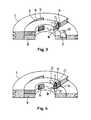
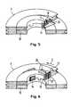
Figur 6- ein weiteres Ausführungsbeispiel in anderer Ansicht
- Figur 8
- einen Schnitt durch Seilrolle und Käfig mit einer erfindungsgemäßen Zentriervorrichtung
It shows:
- Figure 1
- an exploded view of a rotary tensioner according to the invention
- Figure 2
- a front view of the object of Figure 1 - without housing cover and spring cassette
- Figure 3-5, 7
- broken representations of pulley and cage in different embodiments
- Figure 6
- another embodiment in a different view
- Figure 8
- a section through pulley and cage with a centering device according to the invention
In Figur 1 ist ein herkömmlicher, radial sperrender Sicherheitsgurtautomat gezeigt. In einem U-förmig gebogenen Rahmenblech 1 befinden sich zwei Ausnehmungen 2, die an ihrer Oberseite gezahnt ausgebildet sind. An die eine Seite des Rahmens 1 ist ein Gehäuse 3 angebracht, das den oder die üblichen Sensoren enthält. Das Gurtband 4 ist auf der Spule 5 aufgewickelt. Die Spule 5 ist an beiden Seiten fest mit gezahnten Scheiben 6 verbunden. Die Achse der Spule 5 ist so gelagert, daß sie von hier nicht gezeigten Federn in ihrer Neutralstellung gehalten wird und gegen diese Federkraft so nach oben gezogen werden kann, daß die Zahnung der Scheiben 6 in die Zahnung des Rahmenbleches 1 eingreift. In axialer Richtung schließt sich an die Spule 5 noch eine feingezahnte Welle 7 und eine im Durchmesser etwas kleinere, grobgezahnte Welle 8 an. Diese Seite der Rotationsstrammvorrichtung wird mit einem Gehäuse 11 und einer Federkassette 12 verschlossen. Eine Seilrolle 9 und ein Käfig 10 sind in der Ruhestellung so in dem Gehäuse 11 montiert, daß sie sich gegenüber diesem nicht verdrehen lassen, daß sich aber die feingezahnte Welle 7 frei bewegen kann. Die grobgezahnte Welle 8 ist fest mit der Feder in der Kassette 12 verbunden. Auf der Seilrolle 9 ist das Seil 13 (Fig. 2) aufgewickelt, das zu einem hier nicht dargestellten beliebigen Energiespeicher führt. Im Käfig 10 sind die Klemmkeile 14 gelagert, so daß ihre Rückseiten sich in die Ausnehmungen 15 der Seilrolle 9 erstrecken.In Figure 1, a conventional, radially locking seat belt machine is shown. In a U-shaped frame plate 1 there are two
Wird nun bei einem Unfall der Energiespeicher ausgelöst, so wirkt auf das Seil eine Kraft in Richtung des Pfeiles A (Fig. 2) und die Seilrolle 9 beginnt sich in Richtung des Pfeiles B zu drehen. Der Käfig 10 wird dabei durch später beschriebene Einrichtungen in seiner Ruhestellung drehfest zum Gehäuse 11 gehalten. Die Klemmkeile 14 gleiten dabei an den schrägen Rampen 16 entlang und werden dadurch zur Mitte gedrückt. Sobald sie sich in Formschluß mit der feingezahnten Welle 7 befinden, wird der Käfig 10 aus seiner drehfesten Arretierung freigegeben. Es sind nun die Spule 5, die Seilrolle 9 und der Käfig 10 in Drehrichtung des Pfeiles B fest miteinander verbunden. Bei weiterer Krafteinwirkung auf das Seil 13 in Pfeilrichtung A dreht sich nun auch die Spule 5 und wickelt den Gurt 4 auf.If the energy storage device is triggered in the event of an accident, a force acts on the rope in the direction of arrow A (FIG. 2) and the
Das Ausführungsbeispiel nach Anspruch 2 ist in Figur 1 und 3 näher beschrieben. Der Käfig 10 ist mit achsparallelen Bohrungen 17 versehen, in denen Stifte 18 geführt sind. Die Stifte 18 ragen auf hier nicht dargestellte Weise in Ausnehmungen des Gehäuses 11. Dieses Ende der Stifte ist als Spitze 19 ausgebildet. Die Seilrolle 9 ist an ihrer Innenseite mit kreissektorförmigen Ansätzen 20 versehen, die in Ausnehmungen 21 des Käfigs 10 geführt sind. In der Ruhestellung befinden sich die Ansätze 20 direkt unter den Bohrungen 17, so daß die Stifte 18 in ihrer Stellung gehalten werden. Dreht sich nun die Seilrolle 9 gegenüber dem Käfig 10, so drücken die Rampen 16 die Klemmkeile 14 zur Mitte hin. Liegen die Klemmkeile 14 an der Welle 7 an, so entsteht ein Drehmoment, das auf den Käfig 10 wirkt. Bedingt durch dieses Drehmoment und ihre Spitze 19 sind die Stifte 18 bestrebt, sich in Richtung des Pfeiles C zu bewegen. Sobald daher die Ansätze 20 die Stifte 18 freigeben, ziehen sich diese in die Ausnehmung 21 zurück. Der Käfig 10 ist nun gegenüber dem Gehäuse 11 frei drehbar.The embodiment of
In der Figur 4 ist ein weiteres Ausführungsbeispiel dargestellt. Hier ist zusätzlich zum Stift 18 und der axialen Bohrung 17 eine weitere radiale Bohrung 23 und ein Stift 24 vorgesehen. Es ist gestrichelt angedeutet, daß die Bohrung 17 länger ist als in Figur 3 dargestellt. Die Stifte 18 und 24 sind an den Enden, an denen sie sich berühren, mit einer 45°-Schräge 25 versehen.Another exemplary embodiment is shown in FIG. In addition to the
Sind bei einer Drehung der Seilrolle 9 die Klemmkeile 14 voll eingesteuert, so kann sich der Stift 24 in die Ausnehmung 22 in der Seilrolle zurückziehen und gibt somit den Stift 18 frei. Dieser kann sich nun vollkommen in die Bohrung 17 zurückziehen und die Arretierung des Käfigs 10 lösen.If the clamping
Ein weiteres Ausführungsbeispiel ist in Figur 5 beschrieben. Hier wird die Steuerung des Stiftes 18 direkt vom Klemmkeil 14 übernommen. Wenn der Klemmkeil voll eingesteuert ist, fluchtet die Bohrung 26 im Klemmkeil mit der Bohrung 17 im Käfig 10. Der Stift 18 kann sich dann zurückziehen und den Käfig 10 freigeben.Another exemplary embodiment is described in FIG. 5. Here the control of the
In der Figur 6 sind Seilrolle 9 und Käfig 10 so dargestellt, daß die Seite, die dem Aufrollautomaten zugewandt ist, nach oben zeigt. An der Rolle 9 ist ein Ansatz 27 mit einer Führungsrille 28 angeformt. Der Stift 18′ ist so geformt, daß er in der Rille geführt wird. Die Bohrung 17′ ist durch den Käfig 10 durchgehend. Der Ansatz 27 ist in Pfeilrichtung D ansteigend ausgebildet, so daß bei einer Drehung der Seilrolle 9 der Stift 18′ angehoben wird. Es besteht die Möglichkeit, den Ansatz 27 gerade auszubilden, so daß die Führung 28 immer den gleichen Abstand vom Käfig 10 hat. Die Seilrolle 9 muß dann durch eine nicht näher dargestellte Vorrichtung bei ihrer Drehung axial verschoben werden, so daß sich ihr Abstand zum Gehäuse 11 (Fig 1) vergrößert.In Figure 6
Die Steuerung der Haltestifte 18 muß jedoch nicht wegabhängig, sondern kann auch kraftabhängig erfolgen. Ein Beispiel ist in Figur 7 gezeigt.
Hier sitzt der Stift 18 in der Bohrung 17 auf einer Feder 29 auf. Ist der Klemmkeil 14 voll eingesteuert, wirkt ein Drehmoment auf den Käfig 10. Wird dieses Drehmoment so groß, daß die resultierende Kraft, die den Stift 18 entgegen der Feder 29 nach unten in die Bohrung 17 drückt, größer als die Federkraft, so zieht sich der Stift 18 in die Bohrung 17 zurück und gibt den Käfig 10 frei.However, the control of the holding pins 18 does not have to be path-dependent, but can also be force-dependent. An example is shown in Figure 7.
Here the
Auch läßt sich der Käfig über Reibungskräfte drehfest mit dem Gehäuse verbinden. Hierzu kann die entsprechende Seite des Käfigs z.B. mit radialen Rillen oder einem speziellen Belag mit großem Reibungskoeffizienten versehen sein. Auch hier läßt sich der Käfig gegenüber dem Gehäuse erst dann drehen, wenn das auf ihn wirkende Drehmoment größer als die Reibungskräfte zwischen Käfig und Gehäuse ist.The cage can also be connected to the housing in a rotationally fixed manner via frictional forces. For this, the corresponding side of the cage can e.g. be provided with radial grooves or a special covering with a large coefficient of friction. Here, too, the cage can only be rotated relative to the housing when the torque acting on it is greater than the frictional forces between the cage and the housing.
Soll die erfindungsgemäße Vorrichtung bei einem Sicherheitsgurtautomaten mit radial sperrender Hubwelle verwendet werden, wie er in Fig. 1 dargestellt ist, muß die Welle vor dem Strammvorgang zentriert werden. Hierzu sind die Rampen 16 in der Seilrolle 9 unterschiedlich ausgebildet (Fig. 8). Die Rampe 16′, die sich oben in der Nähe der Rahmenverzahnung befindet, ist höher und steiler ausgebildet als die unteren beiden Rampen 16˝.Should the device according to the invention in a seat belt machine are used with a radially locking stroke shaft, as shown in Fig. 1, the shaft must be centered before the tightening process. For this purpose, the
Auch der dazugehörige Klemmkeil 14′ ist länger als die übrigen Klemmkeile 14˝. Dies hat zur Folge, daß der obere Klemmkeil bei gleichem Drehwinkel der Seilrolle einen größeren Weg in Richtung Mittelachse zurücklegt als die beiden anderen Klemmkeile. Die Spule 5 wird dadurch in einer zentrierten Lage fixiert oder, falls sie sich in Blockierstellung befand, in diese Lage gebracht, so daß sie sich während des Strammvorganges ungehindert drehen kann.The associated wedge 14 'is longer than the
Abschließend soll noch erwähnt werden, daß die Vorrichtungen nach den Fig. 1, 3 bis 5 und 7 nicht auf die Verwendung von Stiften beschränkt ist, sondern ebenso z.B. Kugeln zur Anwendung kommen können.Finally, it should be mentioned that the devices according to FIGS. 1, 3 to 5 and 7 are not limited to the use of pins, but also e.g. Balls can be used.
Claims (15)
- Rotary belt tightener for a safety belt device, with an energy storage means releasable by a crash, with a roller (9) actuatable by the energy storage means and serving as a belt tightener drive, and a cage (10) arranged coaxially thereto, in which radially movable clamping elements (14) are carried intercoupling the cage (10) and the roller (9) and positively interlocking with the belt winding axis (7) by a relative rotation of the roller (9) relative to the cage (10),
characterized in
that means for preventing a rotation of the cage (10) relative to the stationary protective housing (11) of the belt tightener roller are provided which are controlled by rotation of the roller (9) to change their position in accordance with a predetermined angle of rotation of the roller (9) relative to the cage (10) in such a manner that the cage (10) is released and is rotatable together with the roller (9). - Rotary belt tightener according to claim 1, characterized in that pins (18) are guided in bores (17) of the cage (10), said bores (17) being parallel to the axis, and held in their locking position by circular sector-shaped shoulders (20) of the roller (9) extending into the cage (10) and covering a part of the bores (17) until the shoulders release the bores (17) completely and the pins (18) are received by them.
- Rotary belt tightener according to claim 1, characterized in that first pins (18) are guided in bores (17) of the cage (10), said bores (17) being parallel to the axis, and that second pins (24), which are guided in radial bores (23) of the cage (10), hold the first pins (18) in their locking position until the cutouts in the roller (9) align with the radial bores (23) of the cage (10).
- Rotary belt tightener according to claim 3, characterized in that the first (18) and second (24) pins are provided with a 45° slope (25) at their respective ends of contact.
- Rotary belt tightener according to claim 1, characterized in that pins (18) are guided in bores (17) of the cage (10), said bores (17) being parallel to the axis, and held in their locking position by the movable clamping elements (14) until the clamping elements (14) are in their position and the pins (18) are completely received in the bores (26) of the clamping elements.
- Rotary belt tightener according to anyone of claims 1 through 5, characterized in that the pins (18) have a tapered form at their end engaging the housing.
- Rotary belt tightener according to claim 1, characterized in that pins guided in bores (17) of the cage (10), said bores (17) being parallel to the axis, are controlled by means of a crank which is connected with the roller (9).
- Rotary belt tightener according to claim 7, characterized in that the crank is provided with a bevelling.
- Rotary belt tightener according to claim 7, characterized in that the crank is formed in parallel to the front surface of the cage (10) and that the roller (9) is displaced in axial direction relative to the cage (10) on rotation by means of a forced control.
- Rotary belt tightener for a safety belt device with an energy storage means releasable by a crash, with a roller (9) actuatable by the energy storage means and serving as belt tightener drive, and a cage (10) coaxially arranged thereto, in which radially movable clamping elements (14) are carried intercoupling the cage (10) and the roller (9) and interlocking with the belt winding axis (7) by a relative rotation of the roller (9) relative to the cage (10), characterized in that spring-tensioned means are provided at the cage (10) or at the stationary protective housing (11) of the belt tightener roller, which prevent a rotation of the cage (10) relative to the stationary protective housing (11), of the belt tightener roller with a predetermined force and release the cage (10) as soon as the torque acting thereupon exceeds said force.
- Rotary belt tightener according to claim 2, 3, 5 or 10, characterized in that balls are used instead of the pins.
- Rotary belt tightener for a safety belt device with an energy storage means releasable by a crash, a roller (9) actuatable by the energy storage means and serving as a belt tightener drive, and a cage (10) arranged coaxially thereto, in which radially movable clamping elements (14) are carried intercoupling the cage (10) and the roller (9) and positively interlocking with the belt winding axis (7) by a relative rotation of the roller (9) relative to the cage (10),
characterized in
that the cage (10) is held by friction in its position to the stationary protective housing (11) of the belt tightener roller until the torque acting thereupon exceeds the static friction. - Rotary belt tightener for a safety belt device with an energy storage means releasable by a crash, a roller (9) actuatable by the energy storage means and serving as belt tightener drive, and a cage (10) coaxially arranged thereto, in which the radially movable clamping elements (14) are held intercoupling the cage (10) and the roller (9) and positively interlocking with the belt winding axis (7) by a relative rotation of the roller (9) relative to the cage (10), the shaft of which is lifted to reach the locked position,
characterized in
that the movable clamping elements (14) have different lengths and that the roller (9) is provided with ramps (16', 16'') of a different bevelling, at which the clamping elements (14', 14'') are guided. - Rotary belt tightener according to claim 13, characterized in that the winding axis (7) is provided with radial ribs in the section of contact of the clamping elements (14).
- Rotary belt tightener according to claim 13 or 14, characterized in that the clamping elements (14) are designed at their inner side such that in case of a crash a positive locking with the radial ribs of the winding axis (7) occurs.
Applications Claiming Priority (2)
| Application Number | Priority Date | Filing Date | Title |
|---|---|---|---|
| DE3735947 | 1987-10-23 | ||
| DE3735947 | 1987-10-23 |
Publications (2)
| Publication Number | Publication Date |
|---|---|
| EP0313098A1 EP0313098A1 (en) | 1989-04-26 |
| EP0313098B1true EP0313098B1 (en) | 1992-06-17 |
Family
ID=6338963
Family Applications (1)
| Application Number | Title | Priority Date | Filing Date |
|---|---|---|---|
| EP88117690AExpired - LifetimeEP0313098B1 (en) | 1987-10-23 | 1988-10-24 | Safety belt-pretensioner |
Country Status (2)
| Country | Link |
|---|---|
| EP (1) | EP0313098B1 (en) |
| DE (1) | DE3872157D1 (en) |
Families Citing this family (5)
| Publication number | Priority date | Publication date | Assignee | Title |
|---|---|---|---|---|
| DE4127957C2 (en)* | 1991-08-23 | 2001-03-01 | Breed Automotive Tech | Coupling for transmitting the back tensioning movement acting on a pull rope to a belt reel of a seat belt automat |
| DE4327134A1 (en)* | 1993-08-12 | 1995-02-16 | Icsrd Rueckhaltesysteme Fuer F | Coupling for transmitting the back tensioning movement acting on a pull rope to a belt reel of a seat belt retractor |
| JPH11247906A (en) | 1998-03-04 | 1999-09-14 | Tokai Rika Co Ltd | Clutch system and webbing winding device |
| DE69918669T2 (en)* | 1999-05-05 | 2004-12-09 | Kabushiki Kaisha Tokai-Rika-Denki-Seisakusho, Niwa | Webbing winding device |
| DE102016118469B4 (en)* | 2016-09-29 | 2025-05-22 | Zf Automotive Germany Gmbh | Belt tensioners |
Family Cites Families (3)
| Publication number | Priority date | Publication date | Assignee | Title |
|---|---|---|---|---|
| DE3131637C2 (en)* | 1980-10-06 | 1986-10-02 | TRW Repa GmbH, 7077 Alfdorf | Back tensioner for seat belt machines |
| JPS61161161U (en)* | 1985-03-29 | 1986-10-06 | ||
| DE3534048A1 (en)* | 1985-09-24 | 1987-04-16 | Trw Repa Gmbh | SAFETY BELT REEL WITH REVERSE DEVICE |
- 1988
- 1988-10-24DEDE8888117690Tpatent/DE3872157D1/ennot_activeExpired - Fee Related
- 1988-10-24EPEP88117690Apatent/EP0313098B1/ennot_activeExpired - Lifetime
Also Published As
| Publication number | Publication date |
|---|---|
| EP0313098A1 (en) | 1989-04-26 |
| DE3872157D1 (en) | 1992-07-23 |
Similar Documents
| Publication | Publication Date | Title |
|---|---|---|
| DE2606293C3 (en) | Device for retracting and rolling up a seat belt | |
| DE2254003C2 (en) | Seat belt retractor with strain relief | |
| DE69608445T2 (en) | SAFETY BELT REEL | |
| DE19541449C2 (en) | Seat belt locking device | |
| DE3330938A1 (en) | PULL-IN DEVICE FOR SAFETY BELTS WITH INTEGRATED BELT LOCK AND PROGRAM CLAMP | |
| DE3407378A1 (en) | SAFETY BELT REEL WITH TIGHTENING DEVICE | |
| DE3017097A1 (en) | SELF-LOCKING BELT REEL FOR MOTOR VEHICLE SAFETY BELTS | |
| DE69935503T2 (en) | Sliding mechanism for a safety scooter | |
| DE69520311T2 (en) | Hoist | |
| DE3227094C2 (en) | Passive vehicle occupant restraint system | |
| EP0231227B1 (en) | Coupling system for the coil shaft of a reel-type safety-belt with restraining device | |
| DE3049564C2 (en) | ||
| DE3009701C2 (en) | ||
| EP0313098B1 (en) | Safety belt-pretensioner | |
| EP0152909B1 (en) | Automatic retraction device for a vehicle safety belt | |
| EP1391357B1 (en) | Seat belt device | |
| EP1285827B1 (en) | Seat belt retractor for a vehicle seat belt | |
| DE10352026A1 (en) | Winder for motor vehicle safety belt has clutch between reel connecting disc and locking disc with pawl | |
| DE102004022401B4 (en) | Belt retractor with pre-tensioner drive | |
| DE2616906A1 (en) | SELF-LOCKING SEAT BELT REWINDING DEVICE | |
| EP0635407B1 (en) | Vehicle safety belt device with pretensioner | |
| EP1685010B1 (en) | Seat-belt tensioner with a belt coupling which can be actively disconnected | |
| DE3328874C2 (en) | ||
| DE69917884T2 (en) | seatbelt | |
| DE2405460C3 (en) | Seat belt retractor |
Legal Events
| Date | Code | Title | Description |
|---|---|---|---|
| PUAI | Public reference made under article 153(3) epc to a published international application that has entered the european phase | Free format text:ORIGINAL CODE: 0009012 | |
| AK | Designated contracting states | Kind code of ref document:A1 Designated state(s):DE ES FR GB IT SE | |
| 17P | Request for examination filed | Effective date:19890524 | |
| 17Q | First examination report despatched | Effective date:19910430 | |
| GRAA | (expected) grant | Free format text:ORIGINAL CODE: 0009210 | |
| AK | Designated contracting states | Kind code of ref document:B1 Designated state(s):DE ES FR GB IT SE | |
| PG25 | Lapsed in a contracting state [announced via postgrant information from national office to epo] | Ref country code:IT Free format text:LAPSE BECAUSE OF FAILURE TO SUBMIT A TRANSLATION OF THE DESCRIPTION OR TO PAY THE FEE WITHIN THE PRE;WARNING: LAPSES OF ITALIAN PATENTS WITH EFFECTIVE DATE BEFORE 2007 MAY HAVE OCCURRED AT ANY TIME BEFORE 2007. THE CORRECT EFFECTIVE DATE MAY BE DIFFERENT FROM THE ONE RECORDED.SCRIBED TIME-LIMIT Effective date:19920617 Ref country code:ES Free format text:THE PATENT HAS BEEN ANNULLED BY A DECISION OF A NATIONAL AUTHORITY Effective date:19920617 Ref country code:FR Effective date:19920617 Ref country code:GB Effective date:19920617 Ref country code:SE Effective date:19920617 | |
| REF | Corresponds to: | Ref document number:3872157 Country of ref document:DE Date of ref document:19920723 | |
| EN | Fr: translation not filed | ||
| GBV | Gb: ep patent (uk) treated as always having been void in accordance with gb section 77(7)/1977 [no translation filed] | ||
| PLBE | No opposition filed within time limit | Free format text:ORIGINAL CODE: 0009261 | |
| STAA | Information on the status of an ep patent application or granted ep patent | Free format text:STATUS: NO OPPOSITION FILED WITHIN TIME LIMIT | |
| 26N | No opposition filed | ||
| PGFP | Annual fee paid to national office [announced via postgrant information from national office to epo] | Ref country code:DE Payment date:19931028 Year of fee payment:6 | |
| PG25 | Lapsed in a contracting state [announced via postgrant information from national office to epo] | Ref country code:DE Effective date:19950701 |