EP0312425B1 - Trailing arm suspension for the rear wheel of a motor vehicle - Google Patents
Trailing arm suspension for the rear wheel of a motor vehicleDownload PDFInfo
- Publication number
- EP0312425B1 EP0312425B1EP19880402490EP88402490AEP0312425B1EP 0312425 B1EP0312425 B1EP 0312425B1EP 19880402490EP19880402490EP 19880402490EP 88402490 AEP88402490 AEP 88402490AEP 0312425 B1EP0312425 B1EP 0312425B1
- Authority
- EP
- European Patent Office
- Prior art keywords
- axis
- rigid part
- pivotal connection
- support
- elastic
- Prior art date
- Legal status (The legal status is an assumption and is not a legal conclusion. Google has not performed a legal analysis and makes no representation as to the accuracy of the status listed.)
- Expired - Lifetime
Links
- 239000000725suspensionSubstances0.000titledescription6
- 229920001971elastomerPolymers0.000claimsdescription5
- 239000000806elastomerSubstances0.000claimsdescription5
- 230000001747exhibiting effectEffects0.000claims1
- 239000002184metalSubstances0.000description3
- 238000006073displacement reactionMethods0.000description2
- 230000010355oscillationEffects0.000description2
- 230000001627detrimental effectEffects0.000description1
- 230000002349favourable effectEffects0.000description1
- 230000003071parasitic effectEffects0.000description1
- 239000007787solidSubstances0.000description1
- 230000003313weakening effectEffects0.000description1
Images
Classifications
- B—PERFORMING OPERATIONS; TRANSPORTING
- B60—VEHICLES IN GENERAL
- B60G—VEHICLE SUSPENSION ARRANGEMENTS
- B60G7/00—Pivoted suspension arms; Accessories thereof
- B60G7/02—Attaching arms to sprung part of vehicle
- B—PERFORMING OPERATIONS; TRANSPORTING
- B60—VEHICLES IN GENERAL
- B60G—VEHICLE SUSPENSION ARRANGEMENTS
- B60G3/00—Resilient suspensions for a single wheel
- B60G3/02—Resilient suspensions for a single wheel with a single pivoted arm
- B60G3/12—Resilient suspensions for a single wheel with a single pivoted arm the arm being essentially parallel to the longitudinal axis of the vehicle
- B60G3/14—Resilient suspensions for a single wheel with a single pivoted arm the arm being essentially parallel to the longitudinal axis of the vehicle the arm being rigid
- B60G3/145—Resilient suspensions for a single wheel with a single pivoted arm the arm being essentially parallel to the longitudinal axis of the vehicle the arm being rigid the arm forming the axle housing
- B—PERFORMING OPERATIONS; TRANSPORTING
- B60—VEHICLES IN GENERAL
- B60G—VEHICLE SUSPENSION ARRANGEMENTS
- B60G2200/00—Indexing codes relating to suspension types
- B60G2200/10—Independent suspensions
- B60G2200/13—Independent suspensions with longitudinal arms only
- B60G2200/132—Independent suspensions with longitudinal arms only with a single trailing arm
- B60G2200/1322—Independent suspensions with longitudinal arms only with a single trailing arm with a wishbone or triangular arm
- B—PERFORMING OPERATIONS; TRANSPORTING
- B60—VEHICLES IN GENERAL
- B60G—VEHICLE SUSPENSION ARRANGEMENTS
- B60G2200/00—Indexing codes relating to suspension types
- B60G2200/40—Indexing codes relating to the wheels in the suspensions
- B60G2200/445—Self-steered wheels
- B—PERFORMING OPERATIONS; TRANSPORTING
- B60—VEHICLES IN GENERAL
- B60G—VEHICLE SUSPENSION ARRANGEMENTS
- B60G2200/00—Indexing codes relating to suspension types
- B60G2200/40—Indexing codes relating to the wheels in the suspensions
- B60G2200/462—Toe-in/out
- B—PERFORMING OPERATIONS; TRANSPORTING
- B60—VEHICLES IN GENERAL
- B60G—VEHICLE SUSPENSION ARRANGEMENTS
- B60G2204/00—Indexing codes related to suspensions per se or to auxiliary parts
- B60G2204/10—Mounting of suspension elements
- B60G2204/14—Mounting of suspension arms
- B60G2204/143—Mounting of suspension arms on the vehicle body or chassis
- B60G2204/1434—Mounting of suspension arms on the vehicle body or chassis in twist-beam axles arrangement
- B—PERFORMING OPERATIONS; TRANSPORTING
- B60—VEHICLES IN GENERAL
- B60G—VEHICLE SUSPENSION ARRANGEMENTS
- B60G2204/00—Indexing codes related to suspensions per se or to auxiliary parts
- B60G2204/40—Auxiliary suspension parts; Adjustment of suspensions
- B60G2204/41—Elastic mounts, e.g. bushings
- B—PERFORMING OPERATIONS; TRANSPORTING
- B60—VEHICLES IN GENERAL
- B60G—VEHICLE SUSPENSION ARRANGEMENTS
- B60G2204/00—Indexing codes related to suspensions per se or to auxiliary parts
- B60G2204/40—Auxiliary suspension parts; Adjustment of suspensions
- B60G2204/41—Elastic mounts, e.g. bushings
- B60G2204/4104—Bushings having modified rigidity in particular directions
- B—PERFORMING OPERATIONS; TRANSPORTING
- B60—VEHICLES IN GENERAL
- B60G—VEHICLE SUSPENSION ARRANGEMENTS
- B60G2204/00—Indexing codes related to suspensions per se or to auxiliary parts
- B60G2204/40—Auxiliary suspension parts; Adjustment of suspensions
- B60G2204/45—Stops limiting travel
Definitions
- the present inventionrelates to a device for articulating a rear wheel support, such as a trailing swing arm, on a structure of a motor vehicle.
- the inventionrelates to an elastic articulation intended to allow the oscillating movement of the rear suspension drawn arm for which the axis of oscillation is perpendicular or slightly oblique with respect to the median plane of the vehicle and located in front of the rear axle .
- the objective of the inventionis therefore to propose an articulation structure making it possible to limit, or even reverse the tendency to open in this type of suspension.
- British patent N ° 984,858discloses an articulation device intended to compensate for the radial deflection of the articulations, responsible for the above opening angle and according to which the two articulations are angularly offset relative to the axis. arm swing. In this way, when a transverse force is exerted on the rear wheel, the outer rings of the joints tend to slide along the axis of each joint. It follows a rotation of the arm in plan in the opposite direction to that caused by the radial deflection of the joints and therefore likely to compensate for the latter.
- the angular offset between the axis of the joints and the axis of oscillation of the arm introduced duringtravel a conical angle, internal to the joint and proportional to the value of the offset, therefore to the desired correction.
- the jointTo absorb this conical angle, the joint must include a more flexible elastomer sleeve (for example thicker radially) which also makes it notably less rigid radially.
- the loss of rigidity of this articulationincreases in the same proportions the deflection during the action of a transverse force and is therefore detrimental to the aim sought, namely to limit the tendency to open this known suspension.
- the object of the present inventionis to produce an elastic articulation for a trailing swing arm which does not have the above drawbacks.
- the articulation device of a rear wheel supportsuch as a trailing swing arm, on a structure of a motor vehicle, which support pivots about an axis substantially transverse to the median longitudinal plane of the vehicle by two elastic articulations spaced axially from one another, one of the articulations being coaxial with the pivot axis of the support
- the second articulationcomprises a rigid part, pivotally mounted on a fixed axis coaxial with the pivot axis of said support and disposed in a through bore of the rigid part which is fitted in a recess of the support with the interposition of an elastic body between the rigid part and the support, which elastic body has great flexibility in one direction substantially horizontal of an axis of the rigid part, inclined relative to the axis pivoting of the support and low flexibility perpendicular to this direction.
- the second articulationis further from the rear wheel than the first articulation and the axis of the rigid part is inclined towards the front of the vehicle with respect to the aforementioned pivot axis on the side of the first joint.
- the elastic bodyis in the form of a sleeve, for example made of elastomer, fitted on a cylindrical outer surface of the rigid part whose axis intersects the pivot axis at a point forming the center of the cylindrical bearing and the fixed axis.
- the above-mentioned elastic sleeveconsists of at least two portions superposed radially and separated by a cylindrical frame.
- the rigid partis pivotally mounted on the aforementioned axis by means of an elastic sleeve having low radial flexibility and comprising a radial extension interposed axially between the rigid part and a fixed part of the vehicle structure.
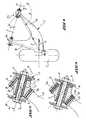
- the reference 1designates a rear wheel support 2 constituted in this case by a swinging arm of the pulled type mounted pivoting about an axis 3 transverse or slightly oblique to the median longitudinal plane of the vehicle (not shown) by two elastic joints A1, A2 spaced axially from each other and each fixed to a structure of the motor vehicle such as the chassis thereof.
- the articulation A1being coaxial with the axis 3, the articulation A2 comprises a rigid part 4 comprising a through or through bore 5 through which is arranged coaxially an axis 6, constituted for example by a solid bolt a fixing yoke 7 itself secured to the chassis of the vehicle.
- the axis of the bolt 6is coaxial with the pivot axis 3 of the arm 1.
- the rigid part 4is pivotally mounted on the axis of the bolt 6 by means of an elastic sleeve 8, for example made of elastomer, and an internal metal sleeve 9 integral with the sleeve 8 inside of it and held between the flanges of the fixing yoke 7, the sleeves 8 and 9 being mounted concentric with the axis of the bolt 6 in the bore 5.
- the sleeve 8, of a relatively small radial thickness and a relatively long large, stiff high radialand preferably comprises a radial extension 10 interposed axially between the rigid part 4 and one of the flanges 11 of the yoke 7.
- the rigid part 4is fitted into a recess or circular opening 12 of the branch 13 of the arm 1 by means of an elastic sleeve 14, for example made of elastomer, fixed by force fitting on a cylindrical surface 15 of the part 4 and an outer metal sleeve 16 superimposed redial with the sleeve 14 and integral with the latter, the sleeve 16 being fixed in the recess 12 by force fitting.
- the sleeves 14 and 16are concentric with the axis 17 of the rigid part 4 or axis of the cylindrical seat 15.
- the axis 17 of the cylindrical seat 15is inclined or offset with respect to the pivot axis 3 of a angle ⁇ and intersects the pivot axis at a point 0 constituting the geometric center common to the cylindrical bearing surface 15 and to the axis of the bolt 6.
- the articulation A2is more distant from the longitudinal median plane of the wheel 2 than the joint A1 and the axis 17 of the cylindrical seat 15 is inclined at the angle ⁇ towards the front of the vehicle with respect to the pivot axis 3 on the side of the joint A1.
- the elastic sleeve 14, of large diameter relative to the elastic sleeve 8has a low axial stiffness or a high axial flexibility in the substantially horizontal direction of the axis 17 of the cylindrical seat 15 and moreover has a high radial stiffness or a low radial flexibility perpendicular to this direction.
- the elastic sleeve 8allows the arm 1 to oscillate without a conical angle, unlike the articulation device of the British patent described above and the sleeve 14, due to its inclination ⁇ relative to the axis 3, forces the rigid part 4 and the metal sleeve 16 to turn as a block with arm 1 during its oscillating movements.
- the force F applied to the arm 1will cause the displacement of the rigid part 4 relative to the arm 1 along the axis 17.
- This displacementcan be amplified by the extension 10 which makes it possible to block any parasitic translation along the pivot axis 3 and reducing the axial stiffness of the sleeve 14 without weakening its radial stiffness. This can be obtained for example by increasing the radial thickness, that is to say, as shown in FIG. 3, by making the sleeve 14 in at least two portions 14a, 14b superposed radially and separated one from the other by a cylindrical frame 19.
- the external articulation A1is also caused to move axially and will preferably have a characteristic of high radial stiffness, combined with a characteristic of low axial stiffness, so as to favor the movement above allowing the creation of '' a pinch angle of the wheel 2 when a transverse force exists predetermined applied to the arm 1 when the vehicle is moving, for example when cornering.
Landscapes
- Engineering & Computer Science (AREA)
- Mechanical Engineering (AREA)
- Vehicle Body Suspensions (AREA)
- Springs (AREA)
Description
Translated fromFrenchLa présente invention concerne un dispositif d'articulation d'un support de roue arrière, tel qu'un bras oscillant tiré, sur une structure d'un véhicule automobile.The present invention relates to a device for articulating a rear wheel support, such as a trailing swing arm, on a structure of a motor vehicle.
Plus particulièrement l'invention est relative à une articulation élastique destinée à permettre le débattement oscillant du bras tiré de suspension arrière pour lequel l'axe d'oscillation est perpendiculaire ou légèrement oblique par rapport au plan médian du véhicule et situé devant l'essieu arrière.More particularly, the invention relates to an elastic articulation intended to allow the oscillating movement of the rear suspension drawn arm for which the axis of oscillation is perpendicular or slightly oblique with respect to the median plane of the vehicle and located in front of the rear axle .
On sait que la roue arrière guidée par un tel bras tend, sous l'influence d'une force transversale, par exemple en virage, à prendre un angle d'ouverture par suite de la déflexion des articulations du bras. Une telle ouverture n'est pas favorable à un bon comportement routier du véhicule.It is known that the rear wheel guided by such an arm tends, under the influence of a transverse force, for example when cornering, to take an opening angle as a result of the deflection of the articulations of the arm. Such an opening is not favorable for good road handling of the vehicle.
L'objectif de l'invention est donc de proposer une structure d'articulation permettant de limiter, voire même d'inverser la tendance à l'ouverture dans ce type de suspension.The objective of the invention is therefore to propose an articulation structure making it possible to limit, or even reverse the tendency to open in this type of suspension.
On connaît par le brevet britannique N° 984 858 un dispositif d'articulation destiné à compenser la déflexion radiale des articulations, responsable de l'angle d'ouverture ci-dessus et selon lequel les deux articulations sont décalées angulairement par rapport à l'axe d'oscillation du bras. De cette façon, lorsqu'une force transversale s'exerce sur la roue arrière, les bagues extérieures des articulations tendent à coulisser suivant l'axe de chaque articulation. Il s'ensuit une rotation du bras en plan dans le sens inverse de celui provoqué par la déflexion radiale des articulations et donc de nature à compenser cette dernière.British patent N ° 984,858 discloses an articulation device intended to compensate for the radial deflection of the articulations, responsible for the above opening angle and according to which the two articulations are angularly offset relative to the axis. arm swing. In this way, when a transverse force is exerted on the rear wheel, the outer rings of the joints tend to slide along the axis of each joint. It follows a rotation of the arm in plan in the opposite direction to that caused by the radial deflection of the joints and therefore likely to compensate for the latter.
Cependant, le décalage angulaire entre l'axe des articulations et l'axe d'oscillation du bras introduit lors du débattement un angle conique, interne à l'articulation et proportionnel à la valeur du décalage, donc à la correction souhaitée. Pour absorber cet angle conique, l'articulation doit comporter un manchon en élastomère plus souple (par exemple plus épais radialement) ce qui la rend aussi notablement moins rigide radialement. La perte de rigidité de cette articulation augmente dans les mêmes proportions la déflexion lors de l'action d'une force transversale et est donc nuisible au but recherché à savoir limiter la tendance à l'ouverture de cette suspension connue.However, the angular offset between the axis of the joints and the axis of oscillation of the arm introduced during travel a conical angle, internal to the joint and proportional to the value of the offset, therefore to the desired correction. To absorb this conical angle, the joint must include a more flexible elastomer sleeve (for example thicker radially) which also makes it notably less rigid radially. The loss of rigidity of this articulation increases in the same proportions the deflection during the action of a transverse force and is therefore detrimental to the aim sought, namely to limit the tendency to open this known suspension.
La présente invention a pour but de réaliser une articulation élastique pour bras oscillant tiré ne présentant pas les inconvénients ci-dessus.The object of the present invention is to produce an elastic articulation for a trailing swing arm which does not have the above drawbacks.
Pour cela, le dispositif d'articulation d'un support de roue arrière, tel qu'un bras oscillant tiré, sur une structure d'un véhicule automobile, lequel support pivote autour d'un axe sensiblement transversal au plan longitudinal médian du véhicule par deux articulations élastiques espacées axialement l'une de l'autre, l'une des articulations étant coaxiale à l'axe de pivotement du support, est caractérisé en ce que la seconde articulation comprend une pièce rigide, montée pivotante sur un axe fixe coaxial à l'axe de pivotement dudit support et disposé dans un alésage traversant de la pièce rigide qui est emmanchée dans un évidement du support avec interposition d'un corps élastique entre la pièce rigide et le support, lequel corps élastique présente une grande flexibilité dans une direction sensiblement horizontale d'un axe de la pièce rigide, inclinée par rapport à l'axe de pivotement du support et une faible flexibilité perpendiculairement à cette direction.For this, the articulation device of a rear wheel support, such as a trailing swing arm, on a structure of a motor vehicle, which support pivots about an axis substantially transverse to the median longitudinal plane of the vehicle by two elastic articulations spaced axially from one another, one of the articulations being coaxial with the pivot axis of the support, is characterized in that the second articulation comprises a rigid part, pivotally mounted on a fixed axis coaxial with the pivot axis of said support and disposed in a through bore of the rigid part which is fitted in a recess of the support with the interposition of an elastic body between the rigid part and the support, which elastic body has great flexibility in one direction substantially horizontal of an axis of the rigid part, inclined relative to the axis pivoting of the support and low flexibility perpendicular to this direction.
Selon une caractéristique de l'invention, la seconde articulation est plus éloignée de la roue arrière que la première articulation et l'axe de la pièce rigide est incliné vers l'avant du véhicule par rapport à l'axe de pivotement précité du côté de la première articulation.According to a characteristic of the invention, the second articulation is further from the rear wheel than the first articulation and the axis of the rigid part is inclined towards the front of the vehicle with respect to the aforementioned pivot axis on the side of the first joint.
Selon une autre caractéristique de l'invention, le corps élastique est en forme de manchon, par exemple en élastomère, emmanché sur une portée extérieure cylindrique de la pièce rigide dont l'axe intersecte l'axe de pivotement en un point formant le centre de la portée cylindrique et de l'axe fixe.According to another characteristic of the invention, the elastic body is in the form of a sleeve, for example made of elastomer, fitted on a cylindrical outer surface of the rigid part whose axis intersects the pivot axis at a point forming the center of the cylindrical bearing and the fixed axis.
Selon encore une autre caractéristique de l'invention, le manchon élastique précité est constitué d'au moins deux portions superposées radialement et séparées par une armature cylindrique.According to yet another characteristic of the invention, the above-mentioned elastic sleeve consists of at least two portions superposed radially and separated by a cylindrical frame.
Selon toujours une autre caractéristique de l'invention, la pièce rigide est montée pivotante sur l'axe précité par l'intermédiaire d'un manchon élastique présentant une faible flexibilité radiale et comportant une extension radiale interposée axialement entre la pièce rigide et une partie fixe de la structure du véhicule.Still according to another characteristic of the invention, the rigid part is pivotally mounted on the aforementioned axis by means of an elastic sleeve having low radial flexibility and comprising a radial extension interposed axially between the rigid part and a fixed part of the vehicle structure.
L'invention sera mieux comprise et d'autres buts, caractéristiques, détails et avantages de celle-ci apparaîtront plus clairement au cours de la description explicative qui va suivre faite en référence aux dessins schématiques annexés donnés uniquement à titre d'exemple illustrant deux modes de réalisation de l'invention et dans lesquels :
- La figure 1 est une vue de dessus d'un bras oscillant tiré de suspension d'une roue arrière d'un véhicule automobile ;
- la figure 2 et une vue en coupe de l'une des articulations élastiques du bras tiré conforme à l'invention ; et
- La figure 3 représente un deuxième mode de réalisation de l'articulation élastique.
- Figure 1 is a top view of a swing arm taken from the suspension of a rear wheel of a motor vehicle;
- Figure 2 and a sectional view of one of the elastic joints of the pulled arm according to the invention; and
- Figure 3 shows a second embodiment of the elastic joint.
En se reportant aux figures 1 et 2, la référence 1 désigne un support de roue arrière 2 constitué dans le cas présent par un bras oscillant du type tiré monté pivotant autour d'un axe 3 transversal ou légèrement oblique par rapport au plan longitudinal médian du véhicule (non représenté) par deux articulations élastiques A1, A2 espacées axialement l'une de l'autre et fixées chacune à une structure du véhicule automobile telle que le châssis de celui-ci.Referring to Figures 1 and 2, the
Selon l'invention, l'articulation A1 étant coaxiale à l'axe 3, l'articulation A2 comprend une pièce rigide 4 comportant un alésage débouchant ou traversant 5 à travers lequel est disposé coaxialement un axe 6, constitué par exemple par un boulon solidaire d'une chape de fixation 7 elle-même solidaire du châssis du véhicule. L'axe du boulon 6 est coaxial à l'axe de pivotement 3 du bras 1.According to the invention, the articulation A1 being coaxial with the axis 3, the articulation A2 comprises a rigid part 4 comprising a through or through bore 5 through which is arranged coaxially an axis 6, constituted for example by a solid bolt a fixing yoke 7 itself secured to the chassis of the vehicle. The axis of the bolt 6 is coaxial with the pivot axis 3 of the
La pièce rigide 4 est montée pivotante sur l'axe du boulon 6 par l'intermédiaire d'un manchon élastique 8, par exemple en élastomère, et d'un manchon métallique intérieur 9 solidaire du manchon 8 à l'intérieur de celui-ci et maintenu entre les flasques de la chape de fixation 7, les manchons 8 et 9 étant montés concentriquement à l'axe du boulon 6 dans l'alésage 5. Le manchon 8, d'une épaisseur radiale relativement faible et d'une longueur relativement grande, présente une raideur radiale élevée et comporte, de préférence, une extension radiale 10 interposée axialement entre la pièce rigide 4 et l'un des flasques 11 de la chape 7.The rigid part 4 is pivotally mounted on the axis of the bolt 6 by means of an elastic sleeve 8, for example made of elastomer, and an internal metal sleeve 9 integral with the sleeve 8 inside of it and held between the flanges of the fixing yoke 7, the sleeves 8 and 9 being mounted concentric with the axis of the bolt 6 in the bore 5. The sleeve 8, of a relatively small radial thickness and a relatively long large, stiff high radial and preferably comprises a
La pièce rigide 4 est emmanchée dans un évidement ou ouverture circulaire 12 de la branche 13 du bras 1 par l'intermédiaire d'un manchon élastique 14, par exemple en élastomère, fixé par emmanchement à force sur une portée cylindrique 15 de la pièce 4 et d'un manchon métallique extérieur 16 superposé redialement au manchon 14 et solidaire de celui-ci, le manchon 16 étant fixé dans l'évidement 12 par emmanchement à force. Les manchons 14 et 16 sont concentriques à l'axe 17 de la pièce rigide 4 ou axe de la portée cylindrique 15. L'axe 17 de la portée cylindrique 15 est incliné ou décalé par rapport à l'axe de pivotement 3 d'un angle α et intersecte l'axe de pivotement en un point 0 constituant le centre géométrique commun à la portée cylindrique 15 et à l'axe du boulon 6. L'articulation A2 est plus éloignée du plan médian longitudinal de la roue 2 que l'articulation A1 et l'axe 17 de la portée cylindrique 15 est incliné suivant l'angle α vers l'avant du véhicule par rapport à l'axe de pivotement 3 du côté de l'articulation A1.The rigid part 4 is fitted into a recess or
Le manchon élastique 14, de grand diamètre par rapport au manchon élastique 8, a une raideur axiale faible ou une flexibilité axiale élevée dans la direction sensiblement horizontale de l'axe 17 de la portée cylindrique 15 et présente de plus une raideur radiale élevée ou une flexibilité radiale faible perpendiculairement à cette direction.The elastic sleeve 14, of large diameter relative to the elastic sleeve 8, has a low axial stiffness or a high axial flexibility in the substantially horizontal direction of the
Le manchon élastique 8 permet l'oscillation du bras 1 sans angle conique contrairement au dispositif d'articulation du brevet britannique décrit précédemment et le manchon 14, du fait de son inclinaison α par rapport à l'axe 3, oblige la pièce rigide 4 et le manchon métallique 16 à tourner en bloc avec le bras 1 lors des mouvements d'oscillation de celui-ci.The elastic sleeve 8 allows the
Lorsqu'une force F transversale au plan médian longitudinal de la roue 2 est appliquée au bras 1, celle-ci se décompose vectoriellement dans la direction des deux articulations A1 et A2 suivant respectivement une composante de force Fi déplaçant dans la direction D de l'axe 17 l'extrémité intérieure de la branche 13 du bras 1 si l'angle β défini entre l'axe 17 et la direction de la force Fi est supérieure à 90° et une composante de force Fe qui tire sur l'extrémité extérieure de la branche 18 du bras 1 et agit normalement à l'axe 3 de l'articulation A1. L'ensemble constitué par le bras 1 et la roue 2 va donc tourner dans le sens du pincement, comme cela est souhaité.When a force F transverse to the longitudinal median plane of the wheel 2 is applied to the
On comprend que la force F appliquée au bras 1 va provoquer le déplacement de la pièce rigide 4 par rapport au bras 1 suivant l'axe 17. Ce déplacement peut être amplifié par l'extension 10 qui permet de bloquer toute translation parasite le long de l'axe de pivotement 3 et en diminuant la raideur axiale du manchon 14 sans affaiblir sa raideur radiale. Ceci peut être obtenu par exemple en augmentant l'épaisseur radiale, c'est-à-dire, comme représenté en figure 3, en réalisant le manchon 14 en au moins deux portions 14a, 14b superposées radialement et séparées l'une de l'autre par une armature cylindrique 19.It is understood that the force F applied to the
L'articulation extérieure A1, de structure classique, est amenée également à se déplacer axialement et possédera de préférence une caractéristique de raideur radiale élevée, combinée avec une caractéristique de raideur axiale faible, de façon à favoriser le mouvement ci-dessus permettant la création d'un angle de pincement de la roue 2 lors de l'existence d'une force transversale prédéterminée appliquée au bras 1 lorsque le véhicule se déplace par exemple en virage.The external articulation A1, of conventional structure, is also caused to move axially and will preferably have a characteristic of high radial stiffness, combined with a characteristic of low axial stiffness, so as to favor the movement above allowing the creation of '' a pinch angle of the wheel 2 when a transverse force exists predetermined applied to the
Claims (6)
Applications Claiming Priority (2)
| Application Number | Priority Date | Filing Date | Title |
|---|---|---|---|
| FR8714129AFR2621534B1 (en) | 1987-10-13 | 1987-10-13 | SWING ARM PULLING SUSPENSION FOR REAR WHEEL OF A MOTOR VEHICLE |
| FR8714129 | 1987-10-13 |
Publications (2)
| Publication Number | Publication Date |
|---|---|
| EP0312425A1 EP0312425A1 (en) | 1989-04-19 |
| EP0312425B1true EP0312425B1 (en) | 1992-02-19 |
Family
ID=9355779
Family Applications (1)
| Application Number | Title | Priority Date | Filing Date |
|---|---|---|---|
| EP19880402490Expired - LifetimeEP0312425B1 (en) | 1987-10-13 | 1988-09-30 | Trailing arm suspension for the rear wheel of a motor vehicle |
Country Status (3)
| Country | Link |
|---|---|
| EP (1) | EP0312425B1 (en) |
| DE (1) | DE3868480D1 (en) |
| FR (1) | FR2621534B1 (en) |
Families Citing this family (2)
| Publication number | Priority date | Publication date | Assignee | Title |
|---|---|---|---|---|
| US5791679A (en)* | 1996-08-16 | 1998-08-11 | The Pullman Company | Torque rod configuration |
| DE10304567A1 (en) | 2003-02-05 | 2004-08-19 | Audi Ag | Wheel suspension for motor vehicles |
Family Cites Families (3)
| Publication number | Priority date | Publication date | Assignee | Title |
|---|---|---|---|---|
| US4046403A (en)* | 1975-02-17 | 1977-09-06 | Mitsubishi Jidosha Kogyo Kabushiki Kaisha | Strut type independent suspension system for automobiles |
| JPS54172415U (en)* | 1978-05-24 | 1979-12-05 | ||
| EP0070025A3 (en)* | 1981-07-14 | 1983-09-28 | Nissan Motor Co., Ltd. | Trailing arm suspension for an automotive vehicle |
- 1987
- 1987-10-13FRFR8714129Apatent/FR2621534B1/ennot_activeExpired - Fee Related
- 1988
- 1988-09-30DEDE8888402490Tpatent/DE3868480D1/ennot_activeExpired - Fee Related
- 1988-09-30EPEP19880402490patent/EP0312425B1/ennot_activeExpired - Lifetime
Also Published As
| Publication number | Publication date |
|---|---|
| EP0312425A1 (en) | 1989-04-19 |
| DE3868480D1 (en) | 1992-03-26 |
| FR2621534B1 (en) | 1990-02-09 |
| FR2621534A1 (en) | 1989-04-14 |
Similar Documents
| Publication | Publication Date | Title |
|---|---|---|
| EP0352184B1 (en) | Upper device for a pivotal connection of a spring-damper unit and the frame of a motor car | |
| EP1305175B1 (en) | Elastic articulation with variable radial rigidity | |
| EP0279135B1 (en) | Front wheel suspension and pivot assembly for a motor vehicle | |
| FR2526376A1 (en) | INDEPENDENT SUSPENSION OF AUTOMOTIVE VEHICLE | |
| FR2584658A1 (en) | REAR WHEEL SUSPENSION OF MOTOR VEHICLE | |
| EP0389363B1 (en) | Motor vehicle rear wheel set | |
| FR2541943A1 (en) | WHEEL SUSPENSION FOR MOTOR VEHICLES | |
| EP1265763B1 (en) | Vehicle axle crosspiece with anti-roll articulations and vehicle axle comprising same | |
| EP0489638B1 (en) | Suspension device particularly for steered wheel of automotive vehicle | |
| EP0312425B1 (en) | Trailing arm suspension for the rear wheel of a motor vehicle | |
| EP0486337B1 (en) | Improvements on front axles of automotive vehicles | |
| EP0538116A1 (en) | Suspension particularly with trailing arms for a motor vehicle, with a system for damping longitudinal shocks | |
| FR2750925A1 (en) | Horizontal suspension unit for vehicle wheels | |
| FR2693955A1 (en) | Suspension link for vehicle multi-link suspension - has ball-joint ends with screwed rod adjustable for length between chassis and wheel hub carrier | |
| FR2645802A1 (en) | Motor vehicle rear suspension assembly | |
| EP0292371B1 (en) | Set of steerable motor vehicle wheels with telescopic suspension struts having an inclined spring | |
| EP0131518B1 (en) | Elastic joint and its application to "macpherson"-type suspensions | |
| FR2748699A1 (en) | Vehicle driving wheel suspension | |
| EP1169210A1 (en) | Vehicle with variable guided pendular motion | |
| FR2825763A1 (en) | Arm with ball joint for vehicle rear suspension system has head fitting inside concave cup inside elastomer vibration damping and protective sleeve | |
| EP0569275B1 (en) | Resilient joint with axial displacement in a fixed manner and suspension with such a joint | |
| FR2788473A1 (en) | Automobile rear axle with separate helicoidal spring and absorber with support connecting cross arms via flexible couplings | |
| EP1211106A2 (en) | Motor vehicle suspension | |
| FR2701674A1 (en) | Suspension with a torsion bar and which filters out vibrations for a wheel, particularly a rear wheel, of a motor vehicle | |
| FR2812840A1 (en) | INDEPENDENT WHEEL SUSPENSION, PARTICULARLY FOR FRONT WHEEL SUSPENSION FOR MOTOR VEHICLES |
Legal Events
| Date | Code | Title | Description |
|---|---|---|---|
| PUAI | Public reference made under article 153(3) epc to a published international application that has entered the european phase | Free format text:ORIGINAL CODE: 0009012 | |
| AK | Designated contracting states | Kind code of ref document:A1 Designated state(s):DE GB IT | |
| 17P | Request for examination filed | Effective date:19890522 | |
| 17Q | First examination report despatched | Effective date:19910606 | |
| GRAA | (expected) grant | Free format text:ORIGINAL CODE: 0009210 | |
| AK | Designated contracting states | Kind code of ref document:B1 Designated state(s):DE GB IT | |
| REF | Corresponds to: | Ref document number:3868480 Country of ref document:DE Date of ref document:19920326 | |
| ITF | It: translation for a ep patent filed | ||
| GBT | Gb: translation of ep patent filed (gb section 77(6)(a)/1977) | ||
| PGFP | Annual fee paid to national office [announced via postgrant information from national office to epo] | Ref country code:GB Payment date:19920918 Year of fee payment:5 | |
| PGFP | Annual fee paid to national office [announced via postgrant information from national office to epo] | Ref country code:DE Payment date:19920928 Year of fee payment:5 | |
| PLBE | No opposition filed within time limit | Free format text:ORIGINAL CODE: 0009261 | |
| STAA | Information on the status of an ep patent application or granted ep patent | Free format text:STATUS: NO OPPOSITION FILED WITHIN TIME LIMIT | |
| 26N | No opposition filed | ||
| PG25 | Lapsed in a contracting state [announced via postgrant information from national office to epo] | Ref country code:GB Effective date:19930930 | |
| GBPC | Gb: european patent ceased through non-payment of renewal fee | Effective date:19930930 | |
| PG25 | Lapsed in a contracting state [announced via postgrant information from national office to epo] | Ref country code:DE Effective date:19940601 | |
| PG25 | Lapsed in a contracting state [announced via postgrant information from national office to epo] | Ref country code:IT Free format text:LAPSE BECAUSE OF NON-PAYMENT OF DUE FEES;WARNING: LAPSES OF ITALIAN PATENTS WITH EFFECTIVE DATE BEFORE 2007 MAY HAVE OCCURRED AT ANY TIME BEFORE 2007. THE CORRECT EFFECTIVE DATE MAY BE DIFFERENT FROM THE ONE RECORDED. Effective date:20050930 |