EP0308390B1 - Valve stem packing containment for high pressure, high temperature - Google Patents
Valve stem packing containment for high pressure, high temperatureDownload PDFInfo
- Publication number
- EP0308390B1 EP0308390B1EP88870149AEP88870149AEP0308390B1EP 0308390 B1EP0308390 B1EP 0308390B1EP 88870149 AEP88870149 AEP 88870149AEP 88870149 AEP88870149 AEP 88870149AEP 0308390 B1EP0308390 B1EP 0308390B1
- Authority
- EP
- European Patent Office
- Prior art keywords
- packing
- valve
- wiper
- ring
- valve stem
- Prior art date
- Legal status (The legal status is an assumption and is not a legal conclusion. Google has not performed a legal analysis and makes no representation as to the accuracy of the status listed.)
- Expired
Links
Images


Classifications
- F—MECHANICAL ENGINEERING; LIGHTING; HEATING; WEAPONS; BLASTING
- F16—ENGINEERING ELEMENTS AND UNITS; GENERAL MEASURES FOR PRODUCING AND MAINTAINING EFFECTIVE FUNCTIONING OF MACHINES OR INSTALLATIONS; THERMAL INSULATION IN GENERAL
- F16J—PISTONS; CYLINDERS; SEALINGS
- F16J15/00—Sealings
- F16J15/16—Sealings between relatively-moving surfaces
- F16J15/18—Sealings between relatively-moving surfaces with stuffing-boxes for elastic or plastic packings
- F16J15/182—Sealings between relatively-moving surfaces with stuffing-boxes for elastic or plastic packings with lubricating, cooling or draining means
- F16J15/183—Sealings between relatively-moving surfaces with stuffing-boxes for elastic or plastic packings with lubricating, cooling or draining means using a lantern ring
- F—MECHANICAL ENGINEERING; LIGHTING; HEATING; WEAPONS; BLASTING
- F16—ENGINEERING ELEMENTS AND UNITS; GENERAL MEASURES FOR PRODUCING AND MAINTAINING EFFECTIVE FUNCTIONING OF MACHINES OR INSTALLATIONS; THERMAL INSULATION IN GENERAL
- F16J—PISTONS; CYLINDERS; SEALINGS
- F16J15/00—Sealings
- F16J15/16—Sealings between relatively-moving surfaces
- F16J15/166—Sealings between relatively-moving surfaces with means to prevent the extrusion of the packing
- F—MECHANICAL ENGINEERING; LIGHTING; HEATING; WEAPONS; BLASTING
- F16—ENGINEERING ELEMENTS AND UNITS; GENERAL MEASURES FOR PRODUCING AND MAINTAINING EFFECTIVE FUNCTIONING OF MACHINES OR INSTALLATIONS; THERMAL INSULATION IN GENERAL
- F16K—VALVES; TAPS; COCKS; ACTUATING-FLOATS; DEVICES FOR VENTING OR AERATING
- F16K41/00—Spindle sealings
- F16K41/02—Spindle sealings with stuffing-box ; Sealing rings
Definitions
- This inventionrelates to valve structures used in controlling the flow of fluids, and in particular to an improved valve stem packing containment for sliding stem valves useful in high pressure and high temperature environments.
- fluid valve structure applicationsoccur in environments where the pressure is less than about 6 895 kPa (1000 psi) and the temperature of the fluid is less than about 200° Fahrenheit (94° Celsius).
- certain applications of fluid valvesrequire use in high pressure and high temperature environments.
- valves operating in such pressure and temperature extremesuse graphite packing material rather than TFE (tetrafluorethylene) packing material due to the limiting usage of TFE at the elevated temperatures and pressure.
- the use of graphite packingleads to increased valve stem friction as the valve stem strokes through the packing thereby severely limiting valve operation and leading to increased wear on the packing material.
- US-A-4 364 542discloses a fluid valve according to the preamble of Claim 1.
- This known fluid valve arrangementis said to perform effectively to withstand temperatures up to 250°F, when fluoroplastic or elastomeric materials are used.
- a more suitable materialis a graphite material.
- DE-A 2 412 698is related to valve spindle seals comprising special material selection and layering of the individual packing rings. Damaging heat is kept away from external O-rings.
- GB-A 1 393 063also discloses a particular pressure seal arrangement for use in feeding and pumping systems, more particularly a pressure barrier seal in high pressure pumping and intensifier systems.
- the said arrangementis equipped with a lantern ring arranged between two packings and in fluid communication with a sealing or pressurizing fluid system.
- valve stem packing containmentfor use in high pressure, high temperature conditions which can provide reliable service with a minimum of friction between the sliding valve stem and the packing material and with a minimum of service required. It is also desired that a valve stem packing containment be provided which can extend the useful valve life even in non-elevated pressure and temperature conditions.
- an improved valve stem packing containmentfor use in sliding valves and which is particularly useful in high pressure and high temperature conditions.
- the improved valve for use in high pressure and high temperature conditions around 49 644 kPa (7200 psi) and 232°Cis described in the claims.
- wiper rings formed of a composition materialsuch as a type known in the industry as used for general purpose gasketing provides an effective means of not only inhibiting the extrusion of packing material but also maintaining any such extruded material within the packing bore.
- the present inventionutilizes wiper rings according to the characterising portion of Claim 1.
- V-type TFE packingis utilized with wiper rings on either side of the packing.
- the wiper rings in their preferred formare composed of high temperature organic and/or inorganic fibers with an elastomeric binder. This configuration was maintained within the packing bore by an upper packing follower and a lower packing box ring. The undesired extrusion of packing material on the inside diameter is effectively inhibited. It is preferred that the packing box ring and the packing follower include a close tolerance portion with respect to the packing bore in order to effectively inhibit extrusions on the packing material outside diameter.
- Either single or double packing type configurationsmay be utilized as desired.
- standard O-ring type configurationsmay be substituted. It may be noted that the present invention is useful to inhibit packing extrusion even under less demanding pressure and temperature conditions. Accordingly, the aforementioned upper and lower wiper rings may be utilized in valve structures operating in such less demanding pressure and temperature conditions to similarly inhibit packing extrusion and thereby prolong valve packing life.
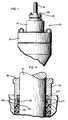
- FIG. 1in which there is illustrated a fluid valve 10 which includes a valve body 12 having a valve bonnet 14 through which is extended a valve stem 16. Packing nuts 18 are threadably mounted on packing studs 20 so as to adjust the loading on packing within the bonnet and around the valve stem.
- a packing 22surrounds valve stem 16 and is formed of a series of rings of the type commonly referred to as V-type packing. As shown in Figure 2,
- V-type packing 22is formed of TFE (tetrafluorethylene - a synthetic resin polymer) and therefore packing 22 is known in the trade as "V-type TFE packing". Packing suitably formed of other material, or of other synthetic resin polymers, may be utilized.
- Each wiper ring 24is located at each end of packing 22.
- Each wiper ringis formed of a composition material and has an inner diameter substantially the same size as the valve stem diameter.
- a most useful composition materialhas been found to be one of high temperature organic and/or inorganic fibers with a nitrile elastomeric binder such that the hardness rating is about 90 plus or minus 5 Shore "B" Durometer.
- the materialshould contain no asbestos or cellulose fiber.
- wiper rings 24are formed of such a composition material and when the wiper ring inner diameter is substantially the same as the valve stem diameter, that the extrusion of material from packing 22 during normal valve operation is inhibited. Without the described wiper rings, significant extrusion of the TFE packing material was experienced under pressures of around 49 644 kPa (7200 psi) and at elevated temperatures of about 450° Fahrenheit (232° Celsius). This undesired extrusion significantly reduces the valve life in that the packing and the valve stem then needs to be replaced quite frequently. On the other hand, in tests using the TFE packing at the elevated pressures and temperatures as before recited, it was found that the use of the composition wiper rings effectively inhibited packing material extrusion during normal sliding valve operation. Therefore sealing integrity of the valve stem packing is maintained.
- the wiper ringstend to maintain any slightly extruded surface material from the packing to be contained within the packing area or at least within the packing containment structure.
- the wiper rings wiping action and containmentis enabled by the use of a sufficiently hard wiper ring material as previously described and by the wiper ring inner diameter substantially matching the valve stem inner diameter. It is preferred that the wiper ring inner diameter have a slight interference fit with the valve stem to insure desired wiper ring operation of the present invention. The desired wiper ring and valve stem operation can be achieved even if the wiper ring is a few thousandths of an inch larger than the valve stem.
- a lantern ring 26is placed around the valve stem and between the two packing sets. As in the conventional use of lantern rings in valves, lantern ring 26 further is adapted in packing bore 28 to enable communication from the valve exterior via access hole 30 and connecting channels 32. This permits lubricating fluid to be inserted into the packing bore and adjacent valve stem 16, and to permit testing for any leakage around the valve stem.
- lantern ring 26includes perimeter portions 34 which are sized to provide a close tolerance, i.e. 0.002 to about 0.005 inch (0.051 to 0.127 mm) diameter tolerance, between the outside diameter of perimeter portion 34 and the diameter of packing bore 28. It has been found that by providing such close tolerance portions 34 that this inhibits any extrusions of material from the packing outer diameter or at least significantly reduces any such packing material extrusion.
- packing follower 36at the upper end of valve stem 16, and a packing box ring 38 at the lower end thereof.
- packing follower 36includes a perimeter portion 40 having a close tolerance between the outside of perimeter portion 40 and the packing bore.
- packing box ring 38includes a perimeter portion 42 with a similar close tolerance.
- Suitable loading of the packing on stem 16is provided by adjusting packing nuts 18 on packing studs 20.
- Conventional guide rings 44 of graphite materialare provided in the packing follower, lantern ring and packing box ring -- all of which may be suitably formed of stainless steel.
- FIG. 3there is illustrated an embodiment of the invention incorporating a single V-type TFE packing.
- a single wiper ring 50is formed as previously described in connection with wipers 24, except the thickness of wiper ring 50 is about twice that of each single wiper ring 24.
- two smaller wipersmay be used in place of the illustrated single layer wiper.
- a packing follower 36 and guide ring 44are located on the valve stem above upper wiper ring 50 and packing 22.
- a coil spring 52suitably formed of, for example, stainless steel is located around the valve stem below packing 22 and lower wiper ring 50.
- a metal washer 54is placed at each end of the coil spring to provide a firm spring base and prevent deformation of the composition material wiper ring.
- Packing box ring 38 and guide ring 44complete the packing containment structure.
- Figure 4illustrates an O-ring wiper 60 held around the valve stem by a retainer 62 at the upper and lower ends of packing 22.
- the O-ringscan be formed of a hard rubber or hard elastomeric resin material and with an inner diameter substantially the same as the valve stem diameter to inhibit packing material extrusion during normal valve operation.
- the O-ring retainerscan be formed with close tolerance perimeter portions 64 as previously described to inhibit extrusion of the packing outer diameter.
Landscapes
- Engineering & Computer Science (AREA)
- General Engineering & Computer Science (AREA)
- Mechanical Engineering (AREA)
- Details Of Valves (AREA)
- Sealing Devices (AREA)
- Sealing With Elastic Sealing Lips (AREA)
Description
- This invention relates to valve structures used in controlling the flow of fluids, and in particular to an improved valve stem packing containment for sliding stem valves useful in high pressure and high temperature environments.
- Normally, fluid valve structure applications occur in environments where the pressure is less than about 6 895 kPa (1000 psi) and the temperature of the fluid is less than about 200° Fahrenheit (94° Celsius). However, certain applications of fluid valves require use in high pressure and high temperature environments. As an example, in the control of boiler feed water in power generating plants there is a requirement for fluid valves operating in pressures around 49 644 kPa (7200 psi) and in temperature ranges of around 450° Fahrenheit (232° Celsius). Normally, valves operating in such pressure and temperature extremes use graphite packing material rather than TFE (tetrafluorethylene) packing material due to the limiting usage of TFE at the elevated temperatures and pressure. The use of graphite packing leads to increased valve stem friction as the valve stem strokes through the packing thereby severely limiting valve operation and leading to increased wear on the packing material.
- However, prior attempts to utilize TFE packing at the elevated pressure and temperature ranges was normally not recommended nor found feasible. In such attempts, it was found that the TFE packing material extruded due to the severe pressures and sliding movement of the valve stem which tended to remove the material from the packing in long strands of string-like extrusions. Eventually, the continued removal and extruding of material from the packing led to a loss of sealing ability for the packing and thereby requiring early replacement of the packing material and possibly the valve stem itself.
- US-A-4 364 542 discloses a fluid valve according to the preamble of Claim 1. This known fluid valve arrangement is said to perform effectively to withstand temperatures up to 250°F, when fluoroplastic or elastomeric materials are used. However, for operating temperatures up to 250°F, a more suitable material is a graphite material.
- DE-A 2 412 698 is related to valve spindle seals comprising special material selection and layering of the individual packing rings. Damaging heat is kept away from external O-rings.
- GB-A 1 393 063 also discloses a particular pressure seal arrangement for use in feeding and pumping systems, more particularly a pressure barrier seal in high pressure pumping and intensifier systems. The said arrangement is equipped with a lantern ring arranged between two packings and in fluid communication with a sealing or pressurizing fluid system.
- Accordingly, it is desired to provide an improved valve stem packing containment for use in high pressure, high temperature conditions which can provide reliable service with a minimum of friction between the sliding valve stem and the packing material and with a minimum of service required. It is also desired that a valve stem packing containment be provided which can extend the useful valve life even in non-elevated pressure and temperature conditions.
- In accordance with the principles of the present invention, there is provided an improved valve stem packing containment for use in sliding valves and which is particularly useful in high pressure and high temperature conditions. The improved valve for use in high pressure and high temperature conditions around 49 644 kPa (7200 psi) and 232°C is described in the claims. In accordance with one aspect of the present invention, it has been found that wiper rings formed of a composition material such as a type known in the industry as used for general purpose gasketing provides an effective means of not only inhibiting the extrusion of packing material but also maintaining any such extruded material within the packing bore.
- As compared to the known prior art packing configurations, the present invention utilizes wiper rings according to the characterising portion of Claim 1.
- In a constructed embodiment of the invention utilizing a double packing configuration with a pair of 1/16th inch (1.59 mm) thick wiper rings on each side of a TFE packing set, standard industry cycling tests were performed in which the valve was operated under changing high pressure and high temperature conditions. Under test conditions simulating about a year of valve usage, no measured amount of leakage was detected.
- In a preferred embodiment of the invention, V-type TFE packing is utilized with wiper rings on either side of the packing. The wiper rings in their preferred form are composed of high temperature organic and/or inorganic fibers with an elastomeric binder. This configuration was maintained within the packing bore by an upper packing follower and a lower packing box ring. The undesired extrusion of packing material on the inside diameter is effectively inhibited. It is preferred that the packing box ring and the packing follower include a close tolerance portion with respect to the packing bore in order to effectively inhibit extrusions on the packing material outside diameter.
- Either single or double packing type configurations may be utilized as desired. In addition, instead of the preferred thin flat type wiper rings, standard O-ring type configurations may be substituted. It may be noted that the present invention is useful to inhibit packing extrusion even under less demanding pressure and temperature conditions. Accordingly, the aforementioned upper and lower wiper rings may be utilized in valve structures operating in such less demanding pressure and temperature conditions to similarly inhibit packing extrusion and thereby prolong valve packing life.
- The features of this invention which are believed to be novel are set forth with particularity in the appended claims. The invention may be best understood by reference to the following description taken in conjunction with the accompanying drawings, in which like reference numerals identify like elements in the several figures and in which:
- Figure 1 is a fragmented elevational view illustrating a fluid valve structure incorporating the present invention;
- Figure 2 is a fragmented cross-sectional view illustrating the double packing configuration and including the wiper rings in accordance with one aspect of the present invention;
- Figure 3 is a fragmented sectional view illustrating a single packing configuration in accordance with another aspect of the present invention; and figure 4 is a fragmented sectional view illustrating the use of an O-ring as an alternative embodiment of the present invention.
- Reference may be made to Figure 1 in which there is illustrated a
fluid valve 10 which includes avalve body 12 having avalve bonnet 14 through which is extended avalve stem 16.Packing nuts 18 are threadably mounted onpacking studs 20 so as to adjust the loading on packing within the bonnet and around the valve stem. - Referring now to Figure 2, there is illustrated a preferred embodiment of a double packing configuration. A packing 22
surrounds valve stem 16 and is formed of a series of rings of the type commonly referred to as V-type packing. As shown in Figure 2, - there is an upper and lower packing set. Each set contains five V-rings including a top female ring 22a; three
identical middle rings 22b; and a bottommale ring 22c. V-type packing 22 is formed of TFE (tetrafluorethylene - a synthetic resin polymer) and therefore packing 22 is known in the trade as "V-type TFE packing". Packing suitably formed of other material, or of other synthetic resin polymers, may be utilized. - Two
wiper rings 24 are located at each end of packing 22. Each wiper ring is formed of a composition material and has an inner diameter substantially the same size as the valve stem diameter. A most useful composition material has been found to be one of high temperature organic and/or inorganic fibers with a nitrile elastomeric binder such that the hardness rating is about 90 plus or minus 5 Shore "B" Durometer. Preferably the material should contain no asbestos or cellulose fiber. - It has been found when
wiper rings 24 are formed of such a composition material and when the wiper ring inner diameter is substantially the same as the valve stem diameter, that the extrusion of material from packing 22 during normal valve operation is inhibited. Without the described wiper rings, significant extrusion of the TFE packing material was experienced under pressures of around 49 644 kPa (7200 psi) and at elevated temperatures of about 450° Fahrenheit (232° Celsius). This undesired extrusion significantly reduces the valve life in that the packing and the valve stem then needs to be replaced quite frequently. On the other hand, in tests using the TFE packing at the elevated pressures and temperatures as before recited, it was found that the use of the composition wiper rings effectively inhibited packing material extrusion during normal sliding valve operation. Therefore sealing integrity of the valve stem packing is maintained. - It is believed that extrusion of the packing material during valve operation is inhibited by the wiping action of
wiper rings 24 on the valve stem, thereby tending to prevent long strands of string-like TFE material from forming or from continuing to form as the valve stem is driven through the packing. Secondly, it is believed the wiper rings tend to maintain any slightly extruded surface material from the packing to be contained within the packing area or at least within the packing containment structure. The wiper rings wiping action and containment is enabled by the use of a sufficiently hard wiper ring material as previously described and by the wiper ring inner diameter substantially matching the valve stem inner diameter. It is preferred that the wiper ring inner diameter have a slight interference fit with the valve stem to insure desired wiper ring operation of the present invention. The desired wiper ring and valve stem operation can be achieved even if the wiper ring is a few thousandths of an inch larger than the valve stem. - A
lantern ring 26 is placed around the valve stem and between the two packing sets. As in the conventional use of lantern rings in valves,lantern ring 26 further is adapted in packing bore 28 to enable communication from the valve exterior viaaccess hole 30 and connectingchannels 32. This permits lubricating fluid to be inserted into the packing bore andadjacent valve stem 16, and to permit testing for any leakage around the valve stem. In the present situation,lantern ring 26 includesperimeter portions 34 which are sized to provide a close tolerance, i.e. 0.002 to about 0.005 inch (0.051 to 0.127 mm) diameter tolerance, between the outside diameter ofperimeter portion 34 and the diameter of packing bore 28. It has been found that by providing suchclose tolerance portions 34 that this inhibits any extrusions of material from the packing outer diameter or at least significantly reduces any such packing material extrusion. - The packing is maintained under suitable loading in the packing bore by means of a packing
follower 36 at the upper end ofvalve stem 16, and apacking box ring 38 at the lower end thereof. As in the case of the lantern ring, packingfollower 36 includes aperimeter portion 40 having a close tolerance between the outside ofperimeter portion 40 and the packing bore. Similarly,packing box ring 38 includes aperimeter portion 42 with a similar close tolerance. Suitable loading of the packing onstem 16 is provided by adjusting packingnuts 18 on packingstuds 20. Conventional guide rings 44 of graphite material are provided in the packing follower, lantern ring and packing box ring -- all of which may be suitably formed of stainless steel. - Referring to Figure 3, there is illustrated an embodiment of the invention incorporating a single V-type TFE packing. In this instance, a
single wiper ring 50 is formed as previously described in connection withwipers 24, except the thickness ofwiper ring 50 is about twice that of eachsingle wiper ring 24. Alternatively, two smaller wipers may be used in place of the illustrated single layer wiper. A packingfollower 36 andguide ring 44 are located on the valve stem aboveupper wiper ring 50 and packing 22. Acoil spring 52 suitably formed of, for example, stainless steel is located around the valve stem below packing 22 andlower wiper ring 50. Ametal washer 54 is placed at each end of the coil spring to provide a firm spring base and prevent deformation of the composition material wiper ring.Packing box ring 38 andguide ring 44 complete the packing containment structure. - Rather than single or double flat wiper rings of composition material, other shapes and other material may be used so long as extrusion of packing material is inhibited. As an example, Figure 4 illustrates an O-
ring wiper 60 held around the valve stem by aretainer 62 at the upper and lower ends of packing 22. The O-rings can be formed of a hard rubber or hard elastomeric resin material and with an inner diameter substantially the same as the valve stem diameter to inhibit packing material extrusion during normal valve operation. Also, the O-ring retainers can be formed with closetolerance perimeter portions 64 as previously described to inhibit extrusion of the packing outer diameter. - Whereas the invention has been described in connection with a sliding stem control valve, it is to be understood that the principles can be applied to any situation employing a reciprocating member with a packing seal, such as a pump, air or hydraulic cylinder, etc.
- The foregoing detailed description has been given for clearness of understanding only, and no unnecessary limitations should be understood therefrom, as modifications will be obvious to those skilled in the art.
Claims (6)
characterized in that said wiper ring being formed of high temperature organic or inorganic fiber material with a nitrile elastomeric binder and having a hardness sufficient to enable the wiper rings wiping action and containment, so that the valve can be used in high pressure and high temperature conditions around 49644 kPa (7200 psi) and 232°C.
Applications Claiming Priority (2)
| Application Number | Priority Date | Filing Date | Title |
|---|---|---|---|
| US07/097,617US4886241A (en) | 1987-09-16 | 1987-09-16 | Valve stem packing containment for high pressure, high temperature |
| US97617 | 1987-09-16 |
Publications (2)
| Publication Number | Publication Date |
|---|---|
| EP0308390A1 EP0308390A1 (en) | 1989-03-22 |
| EP0308390B1true EP0308390B1 (en) | 1992-06-17 |
Family
ID=22264306
Family Applications (1)
| Application Number | Title | Priority Date | Filing Date |
|---|---|---|---|
| EP88870149AExpiredEP0308390B1 (en) | 1987-09-16 | 1988-09-15 | Valve stem packing containment for high pressure, high temperature |
Country Status (6)
| Country | Link |
|---|---|
| US (1) | US4886241A (en) |
| EP (1) | EP0308390B1 (en) |
| JP (1) | JPS6474374A (en) |
| AU (1) | AU605628B2 (en) |
| CA (1) | CA1315765C (en) |
| DE (1) | DE3872128T2 (en) |
Cited By (2)
| Publication number | Priority date | Publication date | Assignee | Title |
|---|---|---|---|---|
| US20140183392A1 (en)* | 2012-12-31 | 2014-07-03 | Vetco Gray Inc. | Gate valve arrangement including multi-valve stem and seat assemblies |
| US9989157B2 (en) | 2011-12-21 | 2018-06-05 | Vetco Gray, LLC | Valve vented redundant stem seal system |
Families Citing this family (105)
| Publication number | Priority date | Publication date | Assignee | Title |
|---|---|---|---|---|
| DE3834610A1 (en)* | 1988-10-11 | 1990-04-12 | Loegel Jun | PUMP UNIT |
| GB8903585D0 (en)* | 1989-02-16 | 1989-04-05 | Kent Introl Ltd | Improvements relating to seals |
| DE3932599A1 (en)* | 1989-09-29 | 1991-04-18 | Ruhr Oel Gmbh | SEALING SYSTEM WITH MODIFIED FILLING BUSH |
| US5238252A (en)* | 1990-01-18 | 1993-08-24 | Eisenwerk Heinrich Schilling Gmbh & Co. | Shut-off fittings with a sealing device |
| DE4001233A1 (en)* | 1990-01-18 | 1991-08-01 | Ruhrkohle Ag | SHUT-OFF ARMATURE |
| US4981174A (en)* | 1990-02-14 | 1991-01-01 | White Orvel O | Leakproof stuffing box with external lubrication for polish rod |
| US5058487A (en)* | 1990-05-01 | 1991-10-22 | Litton Industrial Automation Systems, Inc. | Cylinder with radially movable rod |
| US5056758A (en)* | 1990-05-11 | 1991-10-15 | Bramblet John W | Valve stem packing structure |
| US5230498A (en)* | 1990-10-09 | 1993-07-27 | Fisher Controls International, Inc. | Live load packing system |
| US5131666A (en)* | 1990-10-12 | 1992-07-21 | Fisher Controls International, Inc. | Zero clearance anti-extrusion rings for containment of ptfe packing |
| US5056757A (en)* | 1990-10-12 | 1991-10-15 | Fisher Controls International, Inc. | Packing containment for live loaded fugitive emission seals |
| KR950005880B1 (en)* | 1990-12-21 | 1995-06-02 | 피셔 콜트롤스 인터내쇼날 인코포레이티드 | Improved Graphite Packing |
| WO1992013225A1 (en)* | 1991-01-24 | 1992-08-06 | E.I. Du Pont De Nemours And Company | Perfluoroelastomer valve packing |
| WO1992013224A1 (en)* | 1991-01-24 | 1992-08-06 | E.I. Du Pont De Nemours And Company | High temperature perfluoroelastomere valve packing |
| US5549276A (en)* | 1991-01-24 | 1996-08-27 | E. I. Du Pont De Nemours And Company | Valve with perfluoroelastomer packing |
| US5205317A (en)* | 1991-09-12 | 1993-04-27 | Delta Industrial Valves, Inc. | Valve assembly |
| US5178180A (en)* | 1991-09-12 | 1993-01-12 | Parris Wannis C | Valve assembly |
| US5201532A (en)* | 1991-12-12 | 1993-04-13 | Mark Controls Corporation | Flexible non-planar graphite sealing ring |
| US5190264A (en)* | 1992-03-03 | 1993-03-02 | Dresser Industries, Inc. | Adjustable valve packing arrangement |
| US5297805A (en)* | 1992-10-01 | 1994-03-29 | J.M. Clipper Corp. | Sealing ring |
| US5326074A (en)* | 1992-11-06 | 1994-07-05 | Xomox Corporation | Enhanced sealing arrangement for a rotary valve shaft |
| US5295659A (en)* | 1993-07-26 | 1994-03-22 | Dynamic Air, Inc. | Shaft seal for butterfly valve |
| IT1272517B (en)* | 1993-08-13 | 1997-06-23 | Nuovopignone Ind Macchine E Fo | IMPROVEMENTS IN A COMBINED REGULATION VALVE PARTICULARLY SUITABLE FOR THERMOELECTRIC POWER STATIONS |
| US5346136A (en)* | 1993-10-12 | 1994-09-13 | Dover Resources, Inc. | Fuel injection valve |
| US5503406A (en)* | 1993-11-26 | 1996-04-02 | Neles-Jamesbury | Assembly for live loading or valve packings |
| US5657785A (en)* | 1995-12-06 | 1997-08-19 | Atlantic Richfield Company | Method of replacing valve packing |
| US6062570A (en)* | 1996-02-16 | 2000-05-16 | Barber-Colman | Stem sealing system for broad temperature ranges |
| DE19620694C2 (en)* | 1996-05-22 | 2001-02-15 | Xomox Int Gmbh | Valve arrangement |
| US5732731A (en)* | 1996-09-24 | 1998-03-31 | Fmc Corporation | Secondary seal bypass valve for gate valves |
| US5860633A (en)* | 1996-10-28 | 1999-01-19 | Murphy; Ryan E. | Valve seal |
| US5791629A (en)* | 1996-10-31 | 1998-08-11 | Fisher Controls International, Inc. | Bushing-less stem guided control valve |
| DE29903320U1 (en)* | 1999-02-25 | 1999-07-15 | Xomox International GmbH & Co, 88131 Lindau | Fitting |
| GB9918627D0 (en) | 1999-08-07 | 1999-10-13 | Glaxo Group Ltd | Valve |
| GB0004949D0 (en) | 2000-03-02 | 2000-04-19 | Needham David M | Fluid flow proportioning device |
| WO2001079735A1 (en) | 2000-04-13 | 2001-10-25 | Xomox International Gmbh & Co. | Stuffing box for a valve |
| DE20016361U1 (en) | 2000-04-13 | 2001-02-08 | Xomox International GmbH & Co, 88131 Lindau | Valve |
| US6443423B1 (en)* | 2000-07-24 | 2002-09-03 | General Valve, Inc. | Load-profile compensating stuffing-box packing system for valves having stems of uniform cross-section |
| US6561517B2 (en)* | 2001-07-16 | 2003-05-13 | Stealth International, Inc. | Packing device for rotary valves |
| US6796324B2 (en)* | 2001-11-28 | 2004-09-28 | Fisher Controls International, Llc | Fugitive emission collection device |
| DE10162305A1 (en)* | 2001-12-19 | 2003-07-17 | Honeywell Ag | Valve for liquid media |
| JP2003314695A (en)* | 2002-04-18 | 2003-11-06 | Mitsubishi Heavy Ind Ltd | High temperature resisting seal structure, valve having high temperature resisting seal structure, and side thruster for airframe |
| DE10319753A1 (en)* | 2003-04-30 | 2004-11-25 | Carl Freudenberg Kg | sealing arrangement |
| US7118114B2 (en) | 2003-05-15 | 2006-10-10 | Woodward Governor Company | Dynamic sealing arrangement for movable shaft |
| DE10342751B4 (en)* | 2003-09-16 | 2005-08-18 | Samson Ag | sealing arrangement |
| US20050082766A1 (en)* | 2003-10-15 | 2005-04-21 | Fisher Controls International | Low adhesion additive |
| US20050151107A1 (en)* | 2003-12-29 | 2005-07-14 | Jianchao Shu | Fluid control system and stem joint |
| DK1819956T3 (en)* | 2004-11-05 | 2013-01-14 | Petrolvalves Usa | Metal valve spindle seal and sealing system |
| US20060232019A1 (en)* | 2005-04-19 | 2006-10-19 | Garrison Hubert F | Encapsulated back-up system for use with seal system |
| US7219878B1 (en)* | 2005-10-31 | 2007-05-22 | Control Components, Inc. | Live loaded packing for valve |
| US7426936B2 (en) | 2005-11-29 | 2008-09-23 | Woodward Governor Company | Fully independent, redundant fluid energized sealing solution with secondary containment |
| CA2579111C (en)* | 2006-02-17 | 2012-02-07 | Innicor Subsurface Technologies Inc. | Spring/seal element |
| EP2045489B1 (en)* | 2006-07-12 | 2012-10-24 | Kitz Corporation | Shaft seal packing and shaft seal structure for valve |
| US7963502B2 (en)* | 2006-08-25 | 2011-06-21 | Fisher Controls International Llc | Low friction live-loaded packing |
| US7988127B2 (en)* | 2006-12-29 | 2011-08-02 | Gregory J Parra | Valve with self-expanding seals |
| US7883073B2 (en)* | 2008-01-15 | 2011-02-08 | Emerson Process Management Power And Water Solutions, Inc. | Methods and apparatus for adjusting a spring load in an actuator |
| US7931078B2 (en)* | 2008-02-22 | 2011-04-26 | Scope Production Developments Ltd. | Stuffing box apparatus |
| US8727311B2 (en)* | 2008-09-05 | 2014-05-20 | Vat Holding Ag | Vacuum valve with gas-tight shaft penetration |
| US8146885B2 (en) | 2008-10-08 | 2012-04-03 | Emerson Process Management Regulator Technologies, Inc. | Field removable bonnet assemblies for use with valves |
| US8794638B2 (en)* | 2009-02-27 | 2014-08-05 | Halliburton Energy Services, Inc. | Sealing array for high temperature applications |
| US8136792B2 (en)* | 2009-06-19 | 2012-03-20 | Equistar Chemicals, L.P. | Double containment valve system |
| EP2598779A4 (en)* | 2010-07-30 | 2017-05-24 | Swagelok Company | Anti-extrusion packing support |
| NO334295B1 (en)* | 2011-05-09 | 2014-01-27 | Aker Subsea As | Valve usable as a production valve |
| US9022348B2 (en) | 2011-09-01 | 2015-05-05 | Jianchao Shu | Triple offset butterfly valve and rotary for severe services |
| US9512926B2 (en)* | 2011-10-27 | 2016-12-06 | Aegis Flow Technologies, L.L.C. | Butterfly valve and stem sealing assembly |
| DE102012111467B4 (en) | 2011-11-30 | 2019-07-18 | Hanon Systems | Ball valve with external sealing arrangement, in particular for use in motor vehicle refrigerant circuits |
| AU2012391813B2 (en)* | 2012-10-01 | 2016-10-13 | Halliburton Energy Services, Inc. | Well tools having energized seals |
| US9239114B2 (en)* | 2012-11-05 | 2016-01-19 | Parker-Hannifin Corporation | Compressable sealing ring assembly |
| US9558220B2 (en) | 2013-03-04 | 2017-01-31 | Fisher-Rosemount Systems, Inc. | Big data in process control systems |
| US10909137B2 (en) | 2014-10-06 | 2021-02-02 | Fisher-Rosemount Systems, Inc. | Streaming data for analytics in process control systems |
| US10649424B2 (en) | 2013-03-04 | 2020-05-12 | Fisher-Rosemount Systems, Inc. | Distributed industrial performance monitoring and analytics |
| US10649449B2 (en) | 2013-03-04 | 2020-05-12 | Fisher-Rosemount Systems, Inc. | Distributed industrial performance monitoring and analytics |
| US10386827B2 (en) | 2013-03-04 | 2019-08-20 | Fisher-Rosemount Systems, Inc. | Distributed industrial performance monitoring and analytics platform |
| US9665088B2 (en) | 2014-01-31 | 2017-05-30 | Fisher-Rosemount Systems, Inc. | Managing big data in process control systems |
| US10678225B2 (en) | 2013-03-04 | 2020-06-09 | Fisher-Rosemount Systems, Inc. | Data analytic services for distributed industrial performance monitoring |
| US10223327B2 (en) | 2013-03-14 | 2019-03-05 | Fisher-Rosemount Systems, Inc. | Collecting and delivering data to a big data machine in a process control system |
| US10282676B2 (en) | 2014-10-06 | 2019-05-07 | Fisher-Rosemount Systems, Inc. | Automatic signal processing-based learning in a process plant |
| US10866952B2 (en) | 2013-03-04 | 2020-12-15 | Fisher-Rosemount Systems, Inc. | Source-independent queries in distributed industrial system |
| CN104048060B (en) | 2013-03-14 | 2018-02-16 | 费希尔控制国际公司 | A kind of graphite metal valve seal assembly for high-temperature control valve |
| CN203892591U (en) | 2013-03-14 | 2014-10-22 | 费希尔控制国际公司 | Slide bar control valve and compound sealing assembly for high temperature control valve |
| US10031490B2 (en) | 2013-03-15 | 2018-07-24 | Fisher-Rosemount Systems, Inc. | Mobile analysis of physical phenomena in a process plant |
| DE112014001381T5 (en) | 2013-03-15 | 2016-03-03 | Fisher-Rosemount Systems, Inc. Emerson Process Management | Data Modeling Studio |
| US9512934B2 (en)* | 2013-06-18 | 2016-12-06 | Fisher Controls International Llc | Seal assemblies for use with fluid valves |
| US9400061B2 (en) | 2013-07-29 | 2016-07-26 | Fisher Controls International Llc | Fluid valve apparatus having enclosed seals |
| US10168691B2 (en) | 2014-10-06 | 2019-01-01 | Fisher-Rosemount Systems, Inc. | Data pipeline for process control system analytics |
| DE102015217752A1 (en)* | 2015-09-16 | 2017-03-16 | Siemens Aktiengesellschaft | Guide device for a valve stem and valve with the guide device |
| EP3967876B1 (en) | 2016-02-05 | 2024-01-17 | Graco Minnesota Inc. | Fluid pump leakage diversion |
| US10503483B2 (en) | 2016-02-12 | 2019-12-10 | Fisher-Rosemount Systems, Inc. | Rule builder in a process control network |
| JP6783117B2 (en)* | 2016-10-31 | 2020-11-11 | アズビル株式会社 | Control valve |
| US10533666B2 (en)* | 2017-01-12 | 2020-01-14 | The Boeing Company | Sealing structures and valve assemblies including the sealing structures |
| DE202017105035U1 (en)* | 2017-08-22 | 2018-11-23 | Samson Ag | Control valve |
| US10837556B2 (en)* | 2017-09-20 | 2020-11-17 | Fardner Denver Petroleum Pumps Llc | Packing for a well service pump |
| USD895777S1 (en) | 2017-09-20 | 2020-09-08 | Gardner Denver Petroleum Pumps Llc | Header ring |
| US10746320B2 (en)* | 2017-11-09 | 2020-08-18 | Fisher Controls International Llc | Methods and apparatus to install valve packing components |
| US10378656B2 (en)* | 2017-11-10 | 2019-08-13 | Mueller International, Llc | Valve with active seal and shaft blowout prevention device |
| CN110939779A (en)* | 2018-09-25 | 2020-03-31 | 江苏三益石油装备有限公司 | A valve packing sealing device |
| CN109253308A (en)* | 2018-11-29 | 2019-01-22 | 凯斯特阀门集团有限公司 | It is a kind of for improving the filling-material structure for having the sealing performance of valve rod valve |
| US11499644B2 (en) | 2020-08-25 | 2022-11-15 | Emerson Automation Solutions Final Control US LP | Sealing assembly for a knife gate valve |
| CN112283440B (en)* | 2020-10-20 | 2022-03-08 | 吴忠仪表有限责任公司 | Straight-stroke material loss-free high-temperature normal-pressure packing sealing structure |
| US11686394B2 (en) | 2021-01-28 | 2023-06-27 | Mueller International, Llc | Bonded seat valve |
| US11300213B1 (en) | 2021-02-19 | 2022-04-12 | Emerson Automation Solutions Final Control US LP | Floating yoke connection |
| RU2771412C1 (en)* | 2021-03-18 | 2022-05-04 | Владимир Викторович Михайлов | Sealing apparatus (variants) |
| US11976729B2 (en) | 2021-03-23 | 2024-05-07 | Smc Corporation | Shaft sealing structure |
| JP7505455B2 (en)* | 2021-06-30 | 2024-06-25 | トヨタ自動車株式会社 | Tank Retention Device |
| JP7505454B2 (en) | 2021-06-30 | 2024-06-25 | トヨタ自動車株式会社 | Tank Retention Device |
| US12234926B1 (en)* | 2023-08-10 | 2025-02-25 | Fisher Controls International Llc | Packing system of a valve assembly |
Family Cites Families (23)
| Publication number | Priority date | Publication date | Assignee | Title |
|---|---|---|---|---|
| GB805253A (en)* | 1955-11-25 | 1958-12-03 | Trist & Co Ltd Ronald | Improvements relating to packing rings |
| US2973978A (en)* | 1957-08-21 | 1961-03-07 | North American Aviation Inc | Bimaterial back-up ring |
| US3106407A (en)* | 1961-05-02 | 1963-10-08 | Virdean R Mattingly | Packing ring with anti-extrusion end rings |
| US3397893A (en)* | 1966-08-03 | 1968-08-20 | Int Harvester Co | Cylinder construction |
| US3834715A (en)* | 1972-04-26 | 1974-09-10 | Dart Ind Inc | Pressure seal assembly |
| US3907307A (en)* | 1972-11-01 | 1975-09-23 | Exxon Production Research Co | Packing assembly |
| SE367689B (en)* | 1972-12-29 | 1974-06-04 | Tour Agenturer Ab | |
| DE2412698A1 (en)* | 1974-03-16 | 1975-09-25 | Uhde Gmbh Friedrich | PACKING BOX FOR HIGH PRESSURE VALVES |
| US4061157A (en)* | 1976-01-27 | 1977-12-06 | International Telephone And Telegraph Corporation | Reciprocating valve having stem cleaning means |
| JPS5626128Y2 (en)* | 1976-12-07 | 1981-06-20 | ||
| US4177998A (en)* | 1978-08-25 | 1979-12-11 | Acf Industries, Incorporated | Packing gland assembly |
| US4234197A (en)* | 1979-01-19 | 1980-11-18 | Baker International Corporation | Conduit sealing system |
| US4283062A (en)* | 1979-12-26 | 1981-08-11 | Cincinnati Milacron Inc. | Hydraulic injection molding machine stuffing box |
| US4364542A (en)* | 1981-06-18 | 1982-12-21 | Acf Industries, Incorporated | Packing gland assembly |
| NL8203028A (en)* | 1981-07-31 | 1983-02-16 | Smith International | SEALING DEVICE. |
| US4475712A (en)* | 1982-01-07 | 1984-10-09 | Xomox Corporation | Fluid valve and method of making same |
| US4433847A (en)* | 1982-03-25 | 1984-02-28 | Baker Oil Tools, Inc. | Conduit sealing system |
| US4440404A (en)* | 1982-08-09 | 1984-04-03 | Halliburton Company | Packing arrangement |
| US4476772A (en)* | 1982-11-04 | 1984-10-16 | Corbett Elevator Manufacturing Co., Inc. | Caging seal for hydraulic elevator or the like |
| DE3405351C2 (en)* | 1984-02-15 | 1986-06-12 | Bran & Lübbe GmbH, 2000 Norderstedt | High pressure seal |
| US4512586A (en)* | 1984-05-18 | 1985-04-23 | Smith Russell G | Seal with preformed V-shaped packing rings and method |
| US4552369A (en)* | 1984-12-24 | 1985-11-12 | Gray Tool Company | Stem sealing for high pressure valve |
| US4570942A (en)* | 1985-04-22 | 1986-02-18 | Joy Manufacturing Company | Dual diameter valve stem packing |
- 1987
- 1987-09-16USUS07/097,617patent/US4886241A/ennot_activeExpired - Lifetime
- 1988
- 1988-09-05JPJP63220563Apatent/JPS6474374A/enactivePending
- 1988-09-15CACA000577483Apatent/CA1315765C/ennot_activeExpired - Fee Related
- 1988-09-15EPEP88870149Apatent/EP0308390B1/ennot_activeExpired
- 1988-09-15DEDE8888870149Tpatent/DE3872128T2/ennot_activeExpired - Fee Related
- 1988-09-15AUAU22286/88Apatent/AU605628B2/ennot_activeCeased
Cited By (3)
| Publication number | Priority date | Publication date | Assignee | Title |
|---|---|---|---|---|
| US9989157B2 (en) | 2011-12-21 | 2018-06-05 | Vetco Gray, LLC | Valve vented redundant stem seal system |
| US20140183392A1 (en)* | 2012-12-31 | 2014-07-03 | Vetco Gray Inc. | Gate valve arrangement including multi-valve stem and seat assemblies |
| US9759334B2 (en)* | 2012-12-31 | 2017-09-12 | Vetco Gray Inc. | Gate valve arrangement including multi-valve stem and seat assemblies |
Also Published As
| Publication number | Publication date |
|---|---|
| EP0308390A1 (en) | 1989-03-22 |
| DE3872128D1 (en) | 1992-07-23 |
| US4886241A (en) | 1989-12-12 |
| DE3872128T2 (en) | 1993-02-04 |
| AU605628B2 (en) | 1991-01-17 |
| AU2228688A (en) | 1989-03-16 |
| JPS6474374A (en) | 1989-03-20 |
| CA1315765C (en) | 1993-04-06 |
Similar Documents
| Publication | Publication Date | Title |
|---|---|---|
| EP0308390B1 (en) | Valve stem packing containment for high pressure, high temperature | |
| EP0483096B1 (en) | Packing containment for live loaded fugitive emission seals | |
| EP0046774B1 (en) | Stuffing box packing system | |
| US6007070A (en) | Pressure actuated packing assembly | |
| CA2053355C (en) | Zero clearance anti-extrusion rings for containment of ptfe packing | |
| US4451047A (en) | Seal | |
| US4306728A (en) | Sliding surface packing | |
| CA2045314C (en) | Packing for piston and valve machine and a machine applying same | |
| US4576385A (en) | Fluid packing assembly with alternating diverse seal ring elements | |
| AU649485B2 (en) | Live load packing system | |
| JP3229890B2 (en) | Packing equipment | |
| US6910692B2 (en) | Composite elastomeric seal for sealing fluid lines | |
| EP0150591A1 (en) | A sealed fluid swivel joint | |
| US20100219592A1 (en) | Sealing Array for High Temperature Applications | |
| WO1990010808A1 (en) | Seal for a hydraulic ram | |
| GB2089476A (en) | Gate Valve Stem Seals | |
| GB2132726A (en) | Swivel joint | |
| GB2103310A (en) | Seal | |
| NO173407B (en) | SEALING SYSTEM WITH PACKAGE BOX IN CONTROL OR CLOSE LIGHT | |
| US3339932A (en) | Sealing apparatus | |
| US4524981A (en) | Annular seal with V-cut | |
| GB1601674A (en) | Sliding seal for pistons and piston rods | |
| US7770899B1 (en) | Pressure actuated seal carrier | |
| SU1460495A1 (en) | Movable joint seal | |
| SU1760221A1 (en) | Power cylinder piston seal |
Legal Events
| Date | Code | Title | Description |
|---|---|---|---|
| PUAI | Public reference made under article 153(3) epc to a published international application that has entered the european phase | Free format text:ORIGINAL CODE: 0009012 | |
| AK | Designated contracting states | Kind code of ref document:A1 Designated state(s):DE FR GB IT | |
| 17P | Request for examination filed | Effective date:19890812 | |
| 17Q | First examination report despatched | Effective date:19900702 | |
| GRAA | (expected) grant | Free format text:ORIGINAL CODE: 0009210 | |
| AK | Designated contracting states | Kind code of ref document:B1 Designated state(s):DE FR GB IT | |
| REF | Corresponds to: | Ref document number:3872128 Country of ref document:DE Date of ref document:19920723 | |
| ITF | It: translation for a ep patent filed | ||
| ET | Fr: translation filed | ||
| PLBE | No opposition filed within time limit | Free format text:ORIGINAL CODE: 0009261 | |
| STAA | Information on the status of an ep patent application or granted ep patent | Free format text:STATUS: NO OPPOSITION FILED WITHIN TIME LIMIT | |
| 26N | No opposition filed | ||
| PGFP | Annual fee paid to national office [announced via postgrant information from national office to epo] | Ref country code:GB Payment date:19970908 Year of fee payment:10 | |
| PGFP | Annual fee paid to national office [announced via postgrant information from national office to epo] | Ref country code:FR Payment date:19970909 Year of fee payment:10 | |
| PGFP | Annual fee paid to national office [announced via postgrant information from national office to epo] | Ref country code:DE Payment date:19970919 Year of fee payment:10 | |
| PG25 | Lapsed in a contracting state [announced via postgrant information from national office to epo] | Ref country code:GB Free format text:LAPSE BECAUSE OF NON-PAYMENT OF DUE FEES Effective date:19980915 | |
| GBPC | Gb: european patent ceased through non-payment of renewal fee | Effective date:19980915 | |
| PG25 | Lapsed in a contracting state [announced via postgrant information from national office to epo] | Ref country code:FR Free format text:LAPSE BECAUSE OF NON-PAYMENT OF DUE FEES Effective date:19990531 | |
| PG25 | Lapsed in a contracting state [announced via postgrant information from national office to epo] | Ref country code:DE Free format text:LAPSE BECAUSE OF NON-PAYMENT OF DUE FEES Effective date:19990701 | |
| REG | Reference to a national code | Ref country code:FR Ref legal event code:ST | |
| PG25 | Lapsed in a contracting state [announced via postgrant information from national office to epo] | Ref country code:IT Free format text:LAPSE BECAUSE OF NON-PAYMENT OF DUE FEES;WARNING: LAPSES OF ITALIAN PATENTS WITH EFFECTIVE DATE BEFORE 2007 MAY HAVE OCCURRED AT ANY TIME BEFORE 2007. THE CORRECT EFFECTIVE DATE MAY BE DIFFERENT FROM THE ONE RECORDED. Effective date:20050915 |