EP0301359A1 - Device providing geometric coordination of object data produced by two different analysis channels - Google Patents
Device providing geometric coordination of object data produced by two different analysis channelsDownload PDFInfo
- Publication number
- EP0301359A1 EP0301359A1EP88111544AEP88111544AEP0301359A1EP 0301359 A1EP0301359 A1EP 0301359A1EP 88111544 AEP88111544 AEP 88111544AEP 88111544 AEP88111544 AEP 88111544AEP 0301359 A1EP0301359 A1EP 0301359A1
- Authority
- EP
- European Patent Office
- Prior art keywords
- plate
- markings
- patient
- carrier
- ring
- Prior art date
- Legal status (The legal status is an assumption and is not a legal conclusion. Google has not performed a legal analysis and makes no representation as to the accuracy of the status listed.)
- Ceased
Links
Images
Classifications
- A—HUMAN NECESSITIES
- A61—MEDICAL OR VETERINARY SCIENCE; HYGIENE
- A61B—DIAGNOSIS; SURGERY; IDENTIFICATION
- A61B6/00—Apparatus or devices for radiation diagnosis; Apparatus or devices for radiation diagnosis combined with radiation therapy equipment
- A61B6/50—Apparatus or devices for radiation diagnosis; Apparatus or devices for radiation diagnosis combined with radiation therapy equipment specially adapted for specific body parts; specially adapted for specific clinical applications
- A61B6/501—Apparatus or devices for radiation diagnosis; Apparatus or devices for radiation diagnosis combined with radiation therapy equipment specially adapted for specific body parts; specially adapted for specific clinical applications for diagnosis of the head, e.g. neuroimaging or craniography
- A—HUMAN NECESSITIES
- A61—MEDICAL OR VETERINARY SCIENCE; HYGIENE
- A61B—DIAGNOSIS; SURGERY; IDENTIFICATION
- A61B5/00—Measuring for diagnostic purposes; Identification of persons
- A61B5/05—Detecting, measuring or recording for diagnosis by means of electric currents or magnetic fields; Measuring using microwaves or radio waves
- A61B5/055—Detecting, measuring or recording for diagnosis by means of electric currents or magnetic fields; Measuring using microwaves or radio waves involving electronic [EMR] or nuclear [NMR] magnetic resonance, e.g. magnetic resonance imaging
- A—HUMAN NECESSITIES
- A61—MEDICAL OR VETERINARY SCIENCE; HYGIENE
- A61B—DIAGNOSIS; SURGERY; IDENTIFICATION
- A61B5/00—Measuring for diagnostic purposes; Identification of persons
- A61B5/24—Detecting, measuring or recording bioelectric or biomagnetic signals of the body or parts thereof
- A61B5/242—Detecting biomagnetic fields, e.g. magnetic fields produced by bioelectric currents
- A—HUMAN NECESSITIES
- A61—MEDICAL OR VETERINARY SCIENCE; HYGIENE
- A61B—DIAGNOSIS; SURGERY; IDENTIFICATION
- A61B5/00—Measuring for diagnostic purposes; Identification of persons
- A61B5/70—Means for positioning the patient in relation to the detecting, measuring or recording means
- A—HUMAN NECESSITIES
- A61—MEDICAL OR VETERINARY SCIENCE; HYGIENE
- A61B—DIAGNOSIS; SURGERY; IDENTIFICATION
- A61B6/00—Apparatus or devices for radiation diagnosis; Apparatus or devices for radiation diagnosis combined with radiation therapy equipment
- A61B6/08—Auxiliary means for directing the radiation beam to a particular spot, e.g. using light beams
Definitions
- the inventionrelates to a device for assigning geometric information about an examination object, which are obtained in a sectional image device, to measuring points, which are obtained from the same examination object in a measuring device for biomagnetic signals.
- biomagnetic signalsare becoming increasingly important for medical diagnostics (cf. journal “Bild dermaschine", issue 8, 1986, pages 76-83).
- SQUID systemsextremely weak biomagnetic signals can be measured, for example those of the so-called evoked magnetic fields of the human brain, which are of the order of only 10 ⁇ 14 T.
- the test personis accommodated in a magnetically shielded measuring room and his head is scanned without contact using the SQUID system or magnetometer.
- the data obtained with the aid of SQUID technologyare then evaluated using a computer on the basis of a predetermined mathematical model. Additional patient data are required, in particular on the geometry, for example on the structure, size and extent of the brain.
- Such further patient datacan be provided by further examinations, in particular ultrasound, computer tomography (CT) or magnetic resonance (MR) recordings.
- CTcomputer tomography
- MRmagnetic resonance
- the questionis: Which correlation exists between the individual measuring points of the MEG measurement and the contour of the brain, which is determined in a sectional image method and displayed in a sectional image? To put it more generally, the question is: What geometrical assignment of information about an examination object, which was obtained in a sectional imaging device, to measurement points, which were obtained from the same examination object in a measuring device for biomagnetic signals?
- the inventionis based on the object of specifying a device which helps to answer the mentioned question of assignment.
- the rigid supportcan in principle have any structure.
- itcan be designed as a flat plate.
- Thiscan be made of plastic, for example.
- the flat plastic plateis only a simple way of realizing it. Many other shapes are conceivable, for example an angled plate.
- such a deviceis used in such a way that the patient bites on the bite plate and undergoes the sectional examination. Then the bite plate is firmly connected to the measuring apparatus for the biomagnetic signals; the patient bites the bite plate again and a corresponding biomagnetic measurement is carried out in this position.
- the data or information obtained in both proceduresare firmly correlated with one another.
- the measurement with this deviceis carried out according to the above procedures.
- the named bodycan either be a square plate, a cross or a circular disc.
- the deviceWhile in the first-mentioned basic embodiment only the patient's dentition serves as a head fixed point, in the second-mentioned basic embodiment more than one fixed point is required, for example on the patient's head; to During the measurement, the device is brought into a defined position via the changeable pointers mentioned.
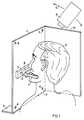
- a combination of bite plate 2 and rigid support 4, which is provided with markings 6 and 6 ',is used as the coordination device. This combination is used to fix the head 8 of a test subject or patient equally in two examination devices.
- a measuring device 10for biomagnetic signals and a medical sectional imaging device (not shown), for example both for an MEG measurement in a predetermined relationship between the carrier 4 and the MEG measuring apparatus and for an MR measurement in the magnetic field of an MR measuring device.
- the bite plate 2is a negative impression of the subject's teeth in a rapidly hardening mass, such as is used for example by the dentist. If the subject bites on the bite plate 2, a rigid coupling between head 8 and bite plate 2 is ensured.
- the bite plate 2can be inserted or inserted into a connection 14 on the carrier 4 via a holder 12. This connection 14 ensures a detachable but rigid attachment between the bite plate 2 and the carrier 4.
- the connection 14can, as shown, be designed in the form of an edge-reinforced insertion opening 15 or a frame placed on the inner surface.
- the connection 14can be made reproducibly adjustable so that it can be adapted to a comfortable position of the patient.
- the carrier 4can in particular be designed as a flat plate made of plastic, for example 20 cm by 20 cm. In the embodiment shown, it also has an angled side plate 4a, here set at 90 °, on which the patient's head 8 rests with his ear.
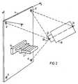
- This combination 2, 4 and possibly 4aboth a defined positioning of the head 8 during the measurement of biomagnetic signals and an assignment of the position of the relevant measuring device 10, e.g. a SQUID gradiometer which can be rotated along a double arrow 16, for the purpose of the sectional image, e.g. head geometry apparent from the MR image.
- the elongated holder 12is integrated into the impression compound already during the manufacture of the bite plate 2, so that a rigid unit is created.
- the bite plate 2can be reproduced via the holder 12, ie repeatedly with high spatial accuracy, with the aid of the connection 14 on the plastic plate 4 can be attached.
- the bite plate 2is only produced once for each test subject, which means little effort, and can then be used as often as desired.
- the head 8is very well fixed since the fixation over the jaw bone and the skull bone is rigid. The positioning between the bite plate 2 and the plastic plate 4 is easily reproducible with a firm bite.
- the sectional view of the head 8, e.g. MR imagingis done with bite plate 2 and plastic plate 4 and, if necessary, 4a. A fixation in the MR device is not necessary.
- the position of the head 8 relative to the plastic plate 4can subsequently be recorded in the MR image, because the plastic plate 4 is indeed with a number of fixed points or markings 6 and 6 ', e.g. with water-filled holes, which can be found in the MR image.
- the reproducibility of the positioningcan be checked very precisely and easily with two or three MR images.
- the plastic plate 4can be fixed relative to the measuring apparatus 10 without any problems by means of the means. Then the exact position, for example relative to the gradiometer array, can be measured within the measuring apparatus 10. Even with a relatively arbitrary attachment of the plate 4 to the measuring apparatus 10, as assumed in FIG. 2, the determination of the position of the head 8 relative to the gradiometer array is reduced to four distance measurements that can be carried out simply and precisely. This is indicated in Fig. 2 by dashed lines. The mutual position and orientation of the plastic plate 4 and the dewar axis 20 of the gradiometer measuring apparatus 10 must be determined by these measurements.
- a gradiometerSQUID array, dewar, holder, etc.
- the plastic plate 4In many cases, a few fixed positions of the plastic plate 4 will be sufficient for the MEG measurement. The position of the plastic plate 4 only needs to be measured once if the relative position of the dewar relative to the head 8 can be adjusted by the movement of the dewar holder. The dewar position and dewar direction 20 are then read on the dewar holder (not shown).
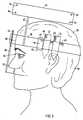
- a differently designed coordination devicecomprises a ring 30 which is rigidly wrapped around the head 28 of a patient.
- An adjusting device 32serves to adjust the ring 30 for the purpose of adaptation to the head diameter; it can be designed like a belt buckle.
- the pointers 34, 35, 36are placed at three prominent points (fixed points) of the head 28, such as in the present example at the center of the two ear canals and the gap between the incisors of the upper jaw.
- the tip of the nose 52, the nasion 54 and / or the inion 56can also be used as fixed points. There is thus a fixed assignment between the fixed points of the head 28 and the reproducibly set pointers 34, 35, 36. That is, the position of the pointers 34, 35, 36 is noted and used in the other measuring methods.
- a geometric body 62is attached to the ring 30 via an adapter 60.
- This body 62is fixed to the ring 30 via the adapter 60, i.e. rigidly connected. It is recognizably shaped for a given slice diagnosis method, i.e. it has e.g. the shape of a plate, a cross or a circular disk, and / or it is provided with spaced markings 64. During MR examinations, the markings 64 can again be filled with holes in a geometrically simple configuration, e.g. in the square. The markings 64 define the position and orientation of the body 62 in space, and thus those of the band 30 and the head 28.
- the rigid ring 30is preferably a non-magnetic band which is wrapped around the patient's head 28.
- the adapter 60is used to attach other bodies 62 to other patients.
- FIGS. 1, 2 and 3can be used wherever a patient is examined using a number of methods, in particular in the case of non-contact methods, and where subsequent therapy measures or operations are particularly accurate with regard to Positioning is required.
Landscapes
- Health & Medical Sciences (AREA)
- Life Sciences & Earth Sciences (AREA)
- Medical Informatics (AREA)
- Engineering & Computer Science (AREA)
- Physics & Mathematics (AREA)
- Heart & Thoracic Surgery (AREA)
- Veterinary Medicine (AREA)
- Public Health (AREA)
- General Health & Medical Sciences (AREA)
- Pathology (AREA)
- Animal Behavior & Ethology (AREA)
- Biomedical Technology (AREA)
- Biophysics (AREA)
- Molecular Biology (AREA)
- Surgery (AREA)
- Nuclear Medicine, Radiotherapy & Molecular Imaging (AREA)
- Radiology & Medical Imaging (AREA)
- High Energy & Nuclear Physics (AREA)
- Optics & Photonics (AREA)
- Neurology (AREA)
- Neurosurgery (AREA)
- Dentistry (AREA)
- Oral & Maxillofacial Surgery (AREA)
- Measuring Magnetic Variables (AREA)
- Magnetic Resonance Imaging Apparatus (AREA)
Abstract
Translated fromGerman
Description
Translated fromGermanDie Erfindung bezieht sich auf eine Vorrichtung zur Zuordnung von geometrischen Informationen über einen Untersuchungsgegenstand, die in einem Schnittbildgerät gewonnen werden, zu Meßpunkten, die von demselben Untersuchungsgegenstand in einer Meßeinrichtung für biomagnetische Signale gewonnen werden.The invention relates to a device for assigning geometric information about an examination object, which are obtained in a sectional image device, to measuring points, which are obtained from the same examination object in a measuring device for biomagnetic signals.
Die Messung biomagnetischer Signale gewinnt für die medizinische Diagnostik immer größere Bedeutung (vgl. Zeitschrift "Bild der Wissenschaft", Heft 8, 1986, Seiten 76-83). Mit Hilfe von sog. SQUID-Systemen lassen sich äußerst schwache biomagnetische Signale meßtechnisch erfassen, z.B. die der sog. evozierten Magnetfelder des menschlichen Gehirns, die in der Größenordnung von nur 10⁻¹⁴ T liegen. Der Proband ist bei einer solchen Messung in einem magnetisch abgeschirmten Meßraum untergebracht, und sein Kopf wird mit dem SQUID-System oder -Magnetometer berührungslos abgetastet. Die mit Hilfe der SQUID-Technologie gewonnenen Daten werden sodann mit Hilfe eines Computers unter Zugrundelegung eines vorgegebenen mathematischen Modells ausgewertet. Dabei werden weitere Patientendaten benötigt, insbesondere über die Geometrie, beispielsweise über die Struktur, Größe und Ausdehnung des Gehirns. Diese weiteren Patientendaten können durch weitere Untersuchungen, insbesondere Ultraschall-, Computer-Tomographie (CT)- oder magnetische Resonanz (MR)-Aufnahmen, bereitgestellt werden. Hierbei stellt sich das Problem der Koordination der biomagnetischen Meßergebnisse mit den Ergebnissen der anderen bildgebenden Verfahren, also z.B. der betreffenden Ultraschall-, CT- oder MR-Technologie.The measurement of biomagnetic signals is becoming increasingly important for medical diagnostics (cf. journal "Bild der Wissenschaft", issue 8, 1986, pages 76-83). With the help of so-called SQUID systems, extremely weak biomagnetic signals can be measured, for example those of the so-called evoked magnetic fields of the human brain, which are of the order of only 10⁻¹⁴ T. During such a measurement, the test person is accommodated in a magnetically shielded measuring room and his head is scanned without contact using the SQUID system or magnetometer. The data obtained with the aid of SQUID technology are then evaluated using a computer on the basis of a predetermined mathematical model. Additional patient data are required, in particular on the geometry, for example on the structure, size and extent of the brain. These further patient data can be provided by further examinations, in particular ultrasound, computer tomography (CT) or magnetic resonance (MR) recordings. This poses the problem of coordinating the biomagnetic measurement results with the results of the other imaging methods, for example the ultrasound, CT or MR technology in question.
Das angesprochene Problem der Koordination oder Zuordnung läßt sich am Beispiel einer Magneto-Enzephalographie-Messung (MEG) und eines Kernspin-Tomographie-Bildes (MR) noch verdeutlichen, wenn es in Teilprobleme aufgelöst wird:
- a) Bestimmung der Lage und Orientierung des Kopfes des Patienten relativ zum flächenhaften Detektor-Array bei der MEG-Messung;
- b) Fixierung des Kopfes während der MEG-Messung; und
- c) Bestimmung der Lage und Orientierung des Kopfes im MR-Bild relativ zur Lage und Orientierung des Kopfes bei der MEG-Messung, oder umgekehrt.
- a) determining the position and orientation of the patient's head relative to the area detector array in the MEG measurement;
- b) fixation of the head during the MEG measurement; and
- c) Determining the position and orientation of the head in the MR image relative to the position and orientation of the head in the MEG measurement, or vice versa.
Erst wenn die angesprochenen Teilprobleme a) bis c) zufriedenstellend gelöst sind, kann jedem der mit dem SQUID-Gradiometer ermittelten Meßpunkte des Kopfes ein Punkt im MR-Bild eindeutig zugeordnet werden. Allgemeiner formuliert lautet die Fragestellung: Welche Zuordnung existiert zwischen den einzelnen Meßpunkten der MEG-Messung und der Kontur des Gehirns, die in einem Schnittbildverfahren ermittelt und in einem Schnittbild dargestellt wird? Noch allgemeiner formuliert lautet die Fragestellung: Welche geometrische Zuordnung von Informationen über einen Untersuchungsgegenstand, die in einem Schnittbildgerät gewonnen wurden, existiert zu Meßpunkten, die von demselben Untersuchungsgegenstand in einer Meßeinrichtung für biomagnetische Signale gewonnen wurden?Only when the sub-problems a) to c) mentioned have been satisfactorily resolved can a point in the MR image be uniquely assigned to each of the measuring points of the head determined using the SQUID gradiometer. To put it more generally, the question is: Which correlation exists between the individual measuring points of the MEG measurement and the contour of the brain, which is determined in a sectional image method and displayed in a sectional image? To put it more generally, the question is: What geometrical assignment of information about an examination object, which was obtained in a sectional imaging device, to measurement points, which were obtained from the same examination object in a measuring device for biomagnetic signals?
Der Erfindung liegt die Aufgabe zugrunde, eine Vorrichtung anzugeben, die die angesprochene Fragestellung der Zuordnung zu beantworten hilft.The invention is based on the object of specifying a device which helps to answer the mentioned question of assignment.
Die oben unter a) angesprochene Teilaufgabe allein für sich ist nach einer Broschüre "Probe Position Indicator" der Fa. Biomagnetic Technologies, Inc., San Diego, Kalifornien, USA, vom Juli 1986 wie folgt gelöst: Kleine Spulen werden an definierten Punkten des Kopfes (z.B. Nasion, Inion, Ohrkanal) befestigt. Das Magnetfeld eines die Spulen durchfließenden Stroms wird gemessen, und daraus wird als inverse Lösung der Maxwell-Gleichungen die Position der Spulen und somit der definierten Punkte am Kopf errechnet. Eine Koordination zwischen zwei Meßeinrichtungen wird durch die bekannte Lösung nicht bewirkt.The subtask mentioned above under a) alone is based on a brochure "Probe Position Indicator" from Biomagnetic Technologies, Inc., San Diego, California, USA, from July 1986 solved as follows: Small coils are attached to defined points of the head (e.g. nasion, inion, ear canal). The magnetic field of a current flowing through the coils is measured, and from this the position of the coils and thus the defined points on the head is calculated as an inverse solution of the Maxwell equations. Coordination between two measuring devices is not brought about by the known solution.
Das unter Punkt b) angesprochene Teilproblem der Fixierung des Kopfes während der MEG-Messung kann nach der Dissertation "The inverse problem in EEG and MEG with application to visual evoked responses" von Cornelis Johannes Stok, Rijksuniversiteit Leiden, Niederlande, 1986, insbes. Seite 46 und Fig. 3.4, durch ein Mundstück oder eine Beißplatte gelöst werden. Diese Beißplatte dient jedoch nur dazu, den Patienten oder den Probanden in einer vorgegebenen Position in bezug auf das SQUID-Gradiometer zu halten. Eine Koordination wird also auch hier nicht herbeigeführt.The sub-problem of fixation of the head during the MEG measurement mentioned under point b) can, according to the dissertation "The inverse problem in EEG and MEG with application to visual evoked responses" by Cornelis Johannes Stok, Rijksuniversiteit Leiden, Netherlands, 1986, in
Die genannte Aufgabe wird nach einer ersten grundlegenden Ausführungsform erfindungsgemäß gelöst durch
- a) eine Beißplatte, deren Kontur dem Gebiß des Patienten entspricht, und
- b) einen starren Träger, der mit der Beißplatte verbindbar oder verbunden und der mit Markierungen versehen ist.
- a) a bite plate, the contour of which corresponds to the patient's teeth, and
- b) a rigid support which is connectable or connected to the bite plate and which is provided with markings.
Der starre Träger kann prinzipiell einen beliebigen Aufbau haben. Beispielsweise kann er als eine ebene Platte ausgebildet sein. Diese kann beispielsweise aus Kunststoff bestehen. Die ebene Kunststoffplatte ist jedoch nur eine einfache Realisierungsmöglichkeit. Viele andere Formen sind denkbar, beispielsweise eine abgewinkelte Platte. Auch ist es möglich, eine starre Kopplung der Beißplatte mit einem halbkreisförmigen Bügel vorzusehen, der jeweils an den beiden Ohrkanälen des Patienten endet. Durch einen solchen Bügel kann eine Gewichtsentlastung am Kopf des Patienten bewirkt werden.The rigid support can in principle have any structure. For example, it can be designed as a flat plate. This can be made of plastic, for example. However, the flat plastic plate is only a simple way of realizing it. Many other shapes are conceivable, for example an angled plate. It is also possible to provide a rigid coupling of the bite plate with a semicircular bracket, each on the patient's two ear canals ends. Such a bracket can relieve the weight on the patient's head.
Bei der Messung wird mit einer solchen Vorrichtung so vorgegangen, daß der Patient auf die Beißplatte beißt und sich der Schnittbilduntersuchung unterzieht. Danach wird die Beißplatte mit der Meßapparatur für die biomagnetischen Signale fest verbunden; der Patient beißt wieder auf die Beißplatte, und eine entsprechende biomagnetische Messung wird in dieser Position durchgeführt. Die in beiden Prozeduren erhaltenen Daten oder Informationen sind fest miteinander korreliert.During the measurement, such a device is used in such a way that the patient bites on the bite plate and undergoes the sectional examination. Then the bite plate is firmly connected to the measuring apparatus for the biomagnetic signals; the patient bites the bite plate again and a corresponding biomagnetic measurement is carried out in this position. The data or information obtained in both procedures are firmly correlated with one another.
Nach einer zweiten grundlegenden Ausführungsform wird die genannte Aufgabe erfindungsgemäß gelöst durch
- a) einen starren Ring, der um den Patienten schlingbar ist,
- b) eine Anzahl in der Länge veränderbarer Zeiger, die jeweils mit einer Skala versehen und am Ring angebracht sind, und
- c) einen mit dem Ring verbundenen Körper, der für ein vorgegebenes Diagnoseverfahren erkennbar geformt oder markiert ist derart, daß seine Lage und Orientierung im Raum definiert sind.
- a) a rigid ring which can be looped around the patient,
- (b) a number of length - adjustable hands, each with a scale and attached to the ring, and
- c) a body connected to the ring, which is recognizably shaped or marked for a given diagnostic procedure in such a way that its position and orientation in space are defined.
Bei der Messung mit dieser Vorrichtung wird entsprechend obigen Prozeduren vorgegangen.The measurement with this device is carried out according to the above procedures.
Der genannte Körper kann entweder eine eckige Platte, ein Kreuz oder eine Kreisscheibe sein.The named body can either be a square plate, a cross or a circular disc.
Während bei der erstgenannten grundlegenden Ausführungsform nur das Gebiß des Patienten als Kopf-Fixpunkt dient, ist bei der zweitgenannten grundlegenden Ausführungsform mehr als ein Fixpunkt, beispielsweise am Kopf des Patienten, erforderlich; zu diesem wird bei der Messung die Vorrichtung über die genannten veränderbaren Zeiger in eine definierte Position gebracht.While in the first-mentioned basic embodiment only the patient's dentition serves as a head fixed point, in the second-mentioned basic embodiment more than one fixed point is required, for example on the patient's head; to During the measurement, the device is brought into a defined position via the changeable pointers mentioned.
Weitere vorteilhafte Ausgestaltungen sind in den Unteransprüchen gekennzeichnet.Further advantageous refinements are characterized in the subclaims.
Ausführungsbeispiele der Erfindung werden im folgenden anhand von drei Figuren näher erläutert. Es zeigen:
- Fig. 1 eine Koordinations-Vorrichtung mit Beißplatte und starrem Träger in Form einer (abgewinkelten) Kunststoff-Platte;
- Fig. 2 die geometrischen Verhältnisse der Kunststoff-Platte in Bezug auf Bauteile einer Meßeinrichtung für biomagnetische Signale; und
- Fig. 3 eine Koordinations-Vorrichtung mit einem starren Ring und einer Anzahl längenveränderlicher Zeiger.
- Figure 1 is a coordination device with bite plate and rigid support in the form of an (angled) plastic plate.
- Figure 2 shows the geometric relationships of the plastic plate in relation to components of a measuring device for biomagnetic signals. and
- Fig. 3 shows a coordination device with a rigid ring and a number of variable-length pointers.
Nach Fig. 1 und 2 wird als Koordinations-Vorrichtung eine Kombination von Beißplatte 2 und starrem Träger 4, der mit Markierungen 6 und 6′ versehen ist, verwendet. Diese Kombination wird zur Fixierung des Kopfes 8 eines Probanden oder Patienten gleichermaßen in zwei Untersuchungsgeräten verwendet.1 and 2, a combination of bite plate 2 and rigid support 4, which is provided with
Sie wird verwendet einmal in Verbindung mit einer Meßeinrichtung 10 für biomagnetische Signale und einem medizinischen Schnittbildgerät (nicht gezeigt), beispielsweise sowohl bei einer MEG-Messung in vorgegebener Relation zwischen dem Träger 4 und der MEG-Meßapparatur als auch bei einer MR-Messung im Magnetfeld eines MR-Meßgerätes.It is used once in connection with a
Die Beißplatte 2 ist ein Negativ-Abdruck des Gebisses des Probanden in einer schnell aushärtenden Masse, wie sie beispielsweise beim Zahnarzt verwendet wird. Beißt der Proband auf die Beißplatte 2, ist eine starre Kopplung zwischen Kopf 8 und Beißplatte 2 gewährleistet. Die Beißplatte 2 ist über einen Halter 12 in eine Verbindung 14 an dem Träger 4 einführbar-oder einsteckbar. Diese Verbindung 14 gewährleistet eine lösbare, aber starre Befestigung zwischen Beißplatte 2 und Träger 4. Die Verbindung 14 kann dazu, wie gezeigt, in Form einer randseitig verstärkten Einführöffnung 15 oder eines auf der Innenfläche aufgesetzten Rahmens ausgebildet sein. Die Verbindung 14 kann reproduzierbar einstellbar ausgeführt sein, so daß sie an eine jeweils bequeme Position des Patienten angepaßt werden kann.The bite plate 2 is a negative impression of the subject's teeth in a rapidly hardening mass, such as is used for example by the dentist. If the subject bites on the bite plate 2, a rigid coupling between head 8 and bite plate 2 is ensured. The bite plate 2 can be inserted or inserted into a
Der Träger 4 kann insbesondere als eine ebene Platte aus Kunststoff, die beispielsweise 20 cm mal 20 cm groß ist, ausgeführt sein. In der dargestellten Ausgestaltung besitzt sie noch eine winklig, hier unter 90° angesetzte Seitenplatte 4a, auf der der Kopf 8 des Patienten mit seinem Ohr ruht. Mit dieser Kombination 2, 4 und ggf. 4a kann sowohl eine definierte Positionierung des Kopfes 8 während der Messung biomagnetischer Signale als auch eine Zuordnung der Position der betreffenden Meßeinrichtung 10, z.B. eines entlang eines Doppelpfeiles 16 drehbaren SQUID-Gradiometers, zur aus dem Schnittbild, z.B. aus dem MR-Bild ersichtlichen Kopfgeometrie erreicht werden. Dazu ist der Träger 4 mit Befestigungsmitteln 17, z.B. in Form von Einsteckstiften oder Klammern, versehen, die eine Befestigung am raumfesten Stativ (nicht gezeigt) der Meßeinrichtung 10 ermöglichen.The carrier 4 can in particular be designed as a flat plate made of plastic, for example 20 cm by 20 cm. In the embodiment shown, it also has an angled
Bereits bei der Herstellung der Beißplatte 2 ist der länglich ausgestaltete Halter 12 in die Abdruckmasse integriert, so daß eine starre Einheit entsteht. Auf diese Weise kann die Beißplatte 2 über den Halter 12 reproduzierbar, d.h. wiederholt mit hoher Ortsgenauigkeit, mit Hilfe der Verbindung 14 auf die Kunststoff platte 4 aufgesteckt werden. Die Beißplatte 2 wird für jeden Probanden nur einmal hergestellt, was wenig Aufwand bedeutet, und ist dann beliebig oft verwendbar. Der Kopf 8 ist sehr gut fixiert, da die Fixierung über den Kieferknochen und den Schädelknochen starr ist. Die Positionierung zwischen Beißplatte 2 und Kunststoffplatte 4 ist bei festem Biß gut reproduzierbar.The elongated holder 12 is integrated into the impression compound already during the manufacture of the bite plate 2, so that a rigid unit is created. In this way, the bite plate 2 can be reproduced via the holder 12, ie repeatedly with high spatial accuracy, with the aid of the
Die Schnittbild-Aufnahme des Kopfes 8, also z.B. die MR-Aufnahme, erfolgt mit Beißplatte 2 und Kunststoff-Platte 4 und ggf. 4a. Eine Fixierung im MR-Gerät ist nicht notwendig. Die Lage des Kopfes 8 relativ zur Kunststoff-Platte 4 kann nachträglich im MR-Bild erfaßt werden, denn die Kunststoff-Platte 4 ist ja mit einer Anzahl Fixpunkten oder Markierungen 6 und 6', z.B. mit wassergefüllten Löchern versehen, die im MR-Bild wiederzufinden sind. Die Reproduzierbarkeit der Positionierung kann sehr genau und einfach mit zwei oder drei MR-Aufnahmen geprüft werden.The sectional view of the head 8, e.g. MR imaging is done with bite plate 2 and plastic plate 4 and, if necessary, 4a. A fixation in the MR device is not necessary. The position of the head 8 relative to the plastic plate 4 can subsequently be recorded in the MR image, because the plastic plate 4 is indeed with a number of fixed points or
Aus Fig. 2 geht hervor, daß bei der Messung biomagnetischer Signale mit Gradiometer (SQUID-Array, Dewar, Halterung, etc.) die Kunststoff-Platte 4 mittels der Mittel problemlos relativ zur Meßapparatur 10 fixiert werden kann. Dann kann die exakte Position, z.B. relativ zum Gradiometer-Array, innerhalb der Meßapparatur 10 gemessen werden. Auch bei einer relativ willkürlichen Befestigung der Platte 4 an der Meßapparatur 10, wie in Fig. 2 angenommen, ist die Bestimmung der Lage des Kopfes 8 relativ zum Gradiometer-Array auf vier einfach und exakt durchzuführende Entfernungsmessungen reduziert. Dies ist in Fig. 2 durch gestrichelte Linien angedeutet. Es muß durch diese Messungen die gegenseitige Lage und Orientierung der Kunststoff-Platte 4 und der Dewarachse 20 der Gradiometer-Meßapparatur 10 bestimmt werden. Wie ersichtlich, genügt dazu die Messung der Entfernung von drei beabstandeten Markierungen 6′ auf der Kunststoff-Platte 4 relativ zu einer einzigen Markierung 22 auf dem Dewar und von zwei Markierungen 22, 24 auf dem Dewar relativ zu einer Markierung 6′ auf der Kunststoff-Platte 4. Die mathematischen Relationen hierfür ergeben sich aus fundamentalen geometrischen Grundlagen.2 shows that when measuring biomagnetic signals with a gradiometer (SQUID array, dewar, holder, etc.) the plastic plate 4 can be fixed relative to the measuring
In vielen Fällen wird man mit einigen wenigen festen Positionen der Kunststoff-Platte 4 bei der MEG-Messung auskommen. Die Lage der Kunststoff-Platte 4 braucht nur einmal ausgemessen zu werden, wenn die relative Lage des Dewars zum Kopf 8 durch die Bewegung der Dewarhalterung eingestellt werden kann. Dewar-Lage und Dewar-Richtung 20 werden dann an der Dewarhalterung (nicht gezeigt) abgelesen.In many cases, a few fixed positions of the plastic plate 4 will be sufficient for the MEG measurement. The position of the plastic plate 4 only needs to be measured once if the relative position of the dewar relative to the head 8 can be adjusted by the movement of the dewar holder. The dewar position and
Nach Fig. 3 umfaßt eine anders konzipierte Koordinations-Vorrichtung einen Ring 30, der starr um den Kopf 28 eines Patienten geschlungen ist. Eine Verstelleinrichtung 32 dient zur Verstellung des Rings 30 zwecks Anpassung an den Kopfdurchmesser; sie kann wie eine Gürtelschnalle gestaltet sein. An dem Ring 30 befinden sich drei Zeiger 34, 35, 36, von denen nur die Zeiger 34 und 36 direkt sichtbar sind. Diese Zeiger 34, 35, 36 sind jeweils in der Länge veränderbar und jeweils mit einer Skala 44, 45, 46 versehen. Weitere Skalen für die zirkulare Einstellung sind mit 48, 49 bzw. 50 bezeichnet. Die Zeiger 34, 35, 36 werden an drei markante Punkte (Fixpunkte) des Kopfes 28 angelegt, wie z.B. im vorliegenden Beispiel an die Mitte der beiden Ohrkanäle und die Spaltmitte zwischen den Schneidezähnen des Oberkiefers. Alternativ können auch die Nasenspitze 52, das Nasion 54 und/oder das Inion 56 als Fixpunkte verwendet werden. Zwischen den Fixpunkten des Kopfes 28 und den reproduzierbar eingestellten Zeigern 34, 35, 36 besteht somit eine feste Zuordnung. D.h., die Stellung der Zeiger 34, 35, 36 wird notiert und bei den anderen Meßverfahren verwendet.3, a differently designed coordination device comprises a
An dem Ring 30 ist über einen Adapter 60 ein geometrischer Körper 62 angebracht. Dieser Körper 62 ist mit dem Ring 30 über den Adapter 60 fest, d.h. starr verbunden. Er ist für ein vorgegebenes Schnittbild-Diagnose-Verfahren erkennbar geformt, besitzt also z.B. die Form einer Platte, eines Kreuzes oder einer Kreisscheibe, und/oder er ist mit beabstandeten Markierungen 64 versehen. Bei MR-Untersuchungen können die Markierungen 64 wieder flüssigkeitsgefüllte Löcher in geometrisch einfacher Konfiguration, z.B. im Viereck, sein. Die Markierungen 64 definieren Lage und Orientierung des Körpers 62 im Raum, damit auch diejenigen des Bandes 30 und des Kopfes 28. Der starre Ring 30 ist bevorzugt ein nichtmagnetisches Band, das um den Kopf 28 des Patienten geschlungen ist. Der Adapter 60 dient dazu, bei anderen Patienten andere Körper 62 aufzustecken.A
Bei Untersuchungen am Thorax des Patienten wird ein entsprechender Ring um den Thorax gelegt. Die an diesem angebrachten Zeiger werden an die Mamillen und an das obere und das untere Ende des Sternums angelegt. Natürlich können auch hier andere Fixpunkte gewählt werden.When examining the patient's chest, an appropriate ring is placed around the chest. The pointers attached to this are placed on the mamillae and on the upper and lower ends of the sternum. Of course, other fixed points can also be selected here.
Als Diagnoseverfahren zur Herstellung des gewünschten Schnittbildes kommen neben dem obengenannten Verfahren der Kernspin-Tomographie auch die Computer-Tomographie, SPECT, PET und Ultraschall als Bildlieferverfahren für die geometrisch richtige Zuordnung von Signalen in der biomagnetischen Diagnostik in Betracht.In addition to the above-mentioned method of nuclear spin tomography, computer tomography, SPECT, PET and ultrasound can also be considered as diagnostic methods for producing the desired sectional image as image delivery methods for the geometrically correct assignment of signals in biomagnetic diagnostics.
Die in den Figuren 1, 2 und 3 dargestellten Vorrichtungen zur Zuordnung oder Koordination können überall dort zum Einsatz kommen, wo ein Patient mit mehreren Verfahren untersucht wird, insbesondere bei berührungslos arbeitenden Verfahren, und wo bei anschließenden Therapiemaßnahmen oder Operationen eine besonders hohe Genauigkeit bezüglich der Positionierung erforderlich ist.The devices for assignment or coordination shown in FIGS. 1, 2 and 3 can be used wherever a patient is examined using a number of methods, in particular in the case of non-contact methods, and where subsequent therapy measures or operations are particularly accurate with regard to Positioning is required.
Claims (21)
Translated fromGermangekennzeichnet durch
marked by
einen Halter (12), der an der Beißplatte (2) befestigt und der mit dem Träger (4) verbindbar oder verbunden ist.12. The device according to one of claims 1 to 11,characterized by
a holder (12) which is attached to the bite plate (2) and which is connectable or connected to the carrier (4).
gekennzeichnet durch
marked by
Applications Claiming Priority (2)
| Application Number | Priority Date | Filing Date | Title |
|---|---|---|---|
| DE3725325 | 1987-07-30 | ||
| DE3725325 | 1987-07-30 |
Publications (1)
| Publication Number | Publication Date |
|---|---|
| EP0301359A1true EP0301359A1 (en) | 1989-02-01 |
Family
ID=6332745
Family Applications (1)
| Application Number | Title | Priority Date | Filing Date |
|---|---|---|---|
| EP88111544ACeasedEP0301359A1 (en) | 1987-07-30 | 1988-07-18 | Device providing geometric coordination of object data produced by two different analysis channels |
Country Status (3)
| Country | Link |
|---|---|
| US (1) | US4971060A (en) |
| EP (1) | EP0301359A1 (en) |
| JP (1) | JPH061694Y2 (en) |
Cited By (6)
| Publication number | Priority date | Publication date | Assignee | Title |
|---|---|---|---|---|
| EP0365840A1 (en)* | 1988-09-26 | 1990-05-02 | Kunio Kawamura | Method of producing a jaw bone anchored type head positioner |
| WO1990013257A1 (en)* | 1989-05-10 | 1990-11-15 | Fixster Instruments Ab | A device and method for repeatable positioning of a reference element on a human head |
| WO1992004862A1 (en)* | 1990-09-18 | 1992-04-02 | Siemens Aktiengesellschaft | Process and device for the anatomically locally correct allocation of the excitation centres of biomagnetic signals |
| FR2687918A1 (en)* | 1992-02-28 | 1993-09-03 | Beverly | DEVICE FOR CREATING A SOLIDAR THREE-DIMENSIONAL MARK OF THE HEAD OF A PATIENT, SUITABLE FOR RADIOTHERAPY. |
| DE4432890B4 (en)* | 1994-09-15 | 2004-02-19 | Brainlab Ag | Device for detecting the position of irradiation target points |
| DE102022201697A1 (en) | 2022-02-18 | 2023-08-24 | Robert Bosch Gesellschaft mit beschränkter Haftung | Sensor unit and method for detecting brainwave induced magnetic fields |
Families Citing this family (27)
| Publication number | Priority date | Publication date | Assignee | Title |
|---|---|---|---|---|
| US5299253A (en)* | 1992-04-10 | 1994-03-29 | Akzo N.V. | Alignment system to overlay abdominal computer aided tomography and magnetic resonance anatomy with single photon emission tomography |
| US5313944A (en)* | 1992-09-21 | 1994-05-24 | Biomagnetic Technologies, Inc. | Measurement of internal body structure during biomagnetometry |
| US5444754A (en)* | 1993-10-13 | 1995-08-22 | Instrumentarium Corp. | Method for localizing cross-sectional dental X-ray images |
| US5549616A (en)* | 1993-11-02 | 1996-08-27 | Loma Linda University Medical Center | Vacuum-assisted stereotactic fixation system with patient-activated switch |
| US5464411A (en)* | 1993-11-02 | 1995-11-07 | Loma Linda University Medical Center | Vacuum-assisted fixation apparatus |
| US5431162A (en)* | 1993-11-22 | 1995-07-11 | Axialtome Australia Pty. Ltd. | Positioning method and apparatus for x-ray tomography |
| JP2611188B2 (en)* | 1994-11-30 | 1997-05-21 | 工業技術院長 | Biological measurement reference point setting method and apparatus |
| US5588430A (en)* | 1995-02-14 | 1996-12-31 | University Of Florida Research Foundation, Inc. | Repeat fixation for frameless stereotactic procedure |
| JP3881696B2 (en)* | 1995-12-21 | 2007-02-14 | シーメンス コーポレイト リサーチ インコーポレイテツド | X-ray geometry calibration |
| US5835563A (en)* | 1995-12-21 | 1998-11-10 | Siemens Corporate Research, Inc. | Calibration apparatus for X-ray geometry |
| DE19715202B4 (en)* | 1997-04-11 | 2006-02-02 | Brainlab Ag | Referencing device with a mouthpiece |
| US5836878A (en)* | 1997-08-11 | 1998-11-17 | Wisconsin Alumni Research Foundation | Head restraint method and apparatus for use in MRI |
| DE69738156T2 (en)* | 1997-09-27 | 2008-06-12 | Brainlab Ag | Method and device for taking a three-dimensional image of a body part |
| US5921927A (en)* | 1997-11-12 | 1999-07-13 | Axialtome Australia Pty. Ltd. | Positioning method and apparatus for X-ray tomography |
| EP1217949B1 (en) | 1999-10-08 | 2008-12-10 | Gendex Corporation | Positioning apparatus for transversal dental x-ray tomography |
| US6945251B2 (en) | 2001-02-09 | 2005-09-20 | Woodburn Iii Robert T | Apparatus for the stabilization of head position |
| US20050004472A1 (en)* | 2002-08-17 | 2005-01-06 | Greg Pratt | Medical socket contour scanning system |
| CA2533680C (en) | 2003-08-12 | 2014-09-16 | Loma Linda University Medical Center | Modular patient support system |
| US7162322B2 (en)* | 2003-11-28 | 2007-01-09 | The Ohio Willow Wood Company | Custom prosthetic liner manufacturing system and method |
| US7515690B2 (en)* | 2006-05-05 | 2009-04-07 | Mackey J Kevin | Radiological scanning orientation indicator |
| WO2009105703A1 (en) | 2008-02-22 | 2009-08-27 | Loma Linda University Medical Center | Systems and methods for characterizing spatial distortion in 3d imaging systems |
| US20090285356A1 (en)* | 2008-05-16 | 2009-11-19 | Sirona Dental Systems Gmbh | System and method for patient positioning in cone-beam tomography |
| CA2717662A1 (en)* | 2009-10-15 | 2011-04-15 | Hybex Holdings Inc. | Non-invasive dental based animal fiducial array |
| US8235594B2 (en)* | 2009-11-02 | 2012-08-07 | Carn Ronald M | Alignment fixture for X-ray images |
| US9265629B2 (en) | 2011-04-01 | 2016-02-23 | The Ohio Willow Wood Company | Fabric covered polymeric prosthetic liner |
| CN103181775B (en)* | 2011-12-31 | 2016-12-07 | Ge医疗系统环球技术有限公司 | For detecting the method and system of patient body's cursor position |
| US11051737B2 (en)* | 2017-05-19 | 2021-07-06 | Ricoh Company, Ltd. | Biomagnetic measurement method, biomagnetic measuring device, and biomagnetic measuring system |
Citations (5)
| Publication number | Priority date | Publication date | Assignee | Title |
|---|---|---|---|---|
| DE517356C (en)* | 1928-06-12 | 1931-02-02 | Alfred Rona Dr | Device to facilitate the correct adjustment of the main ray during intraoral X-ray imaging of teeth |
| US3577160A (en)* | 1968-01-10 | 1971-05-04 | James E White | X-ray gauging apparatus with x-ray opaque markers in the x-ray path to indicate alignment of x-ray tube, subject and film |
| EP0018276A1 (en)* | 1979-04-23 | 1980-10-29 | Thomson-Csf | Measuring device for anatomic details on tomographies |
| US4319136A (en)* | 1979-11-09 | 1982-03-09 | Jinkins J Randolph | Computerized tomography radiograph data transfer cap |
| EP0193650A1 (en)* | 1985-01-25 | 1986-09-10 | Hanspeter Dr. Delnon | Apparatus for orthoradial panoramic tomography |
Family Cites Families (8)
| Publication number | Priority date | Publication date | Assignee | Title |
|---|---|---|---|---|
| SU745505A1 (en)* | 1977-09-28 | 1980-07-05 | Научно-Исследовательский Институт Экспериментальной Медицины Амн Ссср | Method of guiding stereotaxic tool on target point |
| IT1119226B (en)* | 1979-10-17 | 1986-03-03 | Giulio Preti | PERFECTLY CRANOSTAT PARTICULARLY FOR THE AMBULATORY RADIOGRAPHY OF THE ARTICULATION TEMPORO MANDIBOLARE |
| US4501009A (en)* | 1981-08-17 | 1985-02-19 | New York University | Apparatus for stereotactic surgery |
| US4618978A (en)* | 1983-10-21 | 1986-10-21 | Cosman Eric R | Means for localizing target coordinates in a body relative to a guidance system reference frame in any arbitrary plane as viewed by a tomographic image through the body |
| DE3566737D1 (en)* | 1984-06-21 | 1989-01-12 | Oxford Res Syst | Method and apparatus for obtaining localised nmr spectra |
| DE3530234A1 (en)* | 1985-08-23 | 1987-02-26 | Siemens Ag | DENTAL X-RAY DIAGNOSTIC DEVICE |
| US4736751A (en)* | 1986-12-16 | 1988-04-12 | Eeg Systems Laboratory | Brain wave source network location scanning method and system |
| US4793355A (en)* | 1987-04-17 | 1988-12-27 | Biomagnetic Technologies, Inc. | Apparatus for process for making biomagnetic measurements |
- 1988
- 1988-07-18EPEP88111544Apatent/EP0301359A1/ennot_activeCeased
- 1988-07-27JPJP1988100589Upatent/JPH061694Y2/ennot_activeExpired - Lifetime
- 1988-07-28USUS07/227,305patent/US4971060A/ennot_activeExpired - Fee Related
Patent Citations (5)
| Publication number | Priority date | Publication date | Assignee | Title |
|---|---|---|---|---|
| DE517356C (en)* | 1928-06-12 | 1931-02-02 | Alfred Rona Dr | Device to facilitate the correct adjustment of the main ray during intraoral X-ray imaging of teeth |
| US3577160A (en)* | 1968-01-10 | 1971-05-04 | James E White | X-ray gauging apparatus with x-ray opaque markers in the x-ray path to indicate alignment of x-ray tube, subject and film |
| EP0018276A1 (en)* | 1979-04-23 | 1980-10-29 | Thomson-Csf | Measuring device for anatomic details on tomographies |
| US4319136A (en)* | 1979-11-09 | 1982-03-09 | Jinkins J Randolph | Computerized tomography radiograph data transfer cap |
| EP0193650A1 (en)* | 1985-01-25 | 1986-09-10 | Hanspeter Dr. Delnon | Apparatus for orthoradial panoramic tomography |
Non-Patent Citations (1)
| Title |
|---|
| IEEE TRANSACTIONS ON BIOMEDICAL ENGINEERING, Band BME-32, Nr. 6, Juni 1985, Seiten 455-458, IEEE, New York, US; W.J.J. KOUIJZER et al.: "Neuromagnetic fields evoked by a patterned on-offset stimulus"* |
Cited By (8)
| Publication number | Priority date | Publication date | Assignee | Title |
|---|---|---|---|---|
| EP0365840A1 (en)* | 1988-09-26 | 1990-05-02 | Kunio Kawamura | Method of producing a jaw bone anchored type head positioner |
| US5219288A (en)* | 1988-09-26 | 1993-06-15 | Kunio Kawamura | Jaw bone anchored type positioner |
| WO1990013257A1 (en)* | 1989-05-10 | 1990-11-15 | Fixster Instruments Ab | A device and method for repeatable positioning of a reference element on a human head |
| AU630703B2 (en)* | 1989-05-10 | 1992-11-05 | Fixster Instruments Ab | A device and method for repeatable positioning of a reference element on a human head |
| WO1992004862A1 (en)* | 1990-09-18 | 1992-04-02 | Siemens Aktiengesellschaft | Process and device for the anatomically locally correct allocation of the excitation centres of biomagnetic signals |
| FR2687918A1 (en)* | 1992-02-28 | 1993-09-03 | Beverly | DEVICE FOR CREATING A SOLIDAR THREE-DIMENSIONAL MARK OF THE HEAD OF A PATIENT, SUITABLE FOR RADIOTHERAPY. |
| DE4432890B4 (en)* | 1994-09-15 | 2004-02-19 | Brainlab Ag | Device for detecting the position of irradiation target points |
| DE102022201697A1 (en) | 2022-02-18 | 2023-08-24 | Robert Bosch Gesellschaft mit beschränkter Haftung | Sensor unit and method for detecting brainwave induced magnetic fields |
Also Published As
| Publication number | Publication date |
|---|---|
| JPH061694Y2 (en) | 1994-01-19 |
| JPH0193008U (en) | 1989-06-19 |
| US4971060A (en) | 1990-11-20 |
Similar Documents
| Publication | Publication Date | Title |
|---|---|---|
| EP0301359A1 (en) | Device providing geometric coordination of object data produced by two different analysis channels | |
| EP1273320B1 (en) | Apparatus for transcranial magnetic stimulation | |
| US4228799A (en) | Method of guiding a stereotaxic instrument at an intracerebral space target point | |
| DE69434240T2 (en) | MAGNETIC DETERMINATION OF LOCATION AND ORIENTATION | |
| DE69427211T2 (en) | Apparatus for carrying out magnetic resonance processes | |
| DE69109234T2 (en) | Sensor position indicator measuring coils used in magnetoencephalographic examinations and means for attaching them to the head. | |
| DE69733604T2 (en) | MOVABLE RECEIVING AND TRANSMISSION PANS FOR A LOCAL DETERMINATION SYSTEM | |
| DE19527245A1 (en) | Device for endoscopic or gastroscopic examinations | |
| DE19633200A1 (en) | Method for measuring biomagnetism | |
| DE3838011A1 (en) | METHOD AND DEVICE FOR GENERATING IMAGES OF THE ANATOMY | |
| DE112005000700T5 (en) | An instrument and method for measuring a three-dimensional motion in a living body | |
| EP0668741B1 (en) | Process and device for acceptance and regular testing of filmless dental radiographic equipment | |
| DE9107798U1 (en) | Metal detector for locating a metallic foreign body that has penetrated or been implanted in a human or animal body | |
| DE60310078T2 (en) | METHOD FOR IMAGING THE RELATIVE MOVEMENT OF SKELETAL SEGMENTS | |
| DE69831292T2 (en) | DEVICE FOR IMAGE-SUPPORTED THORAX THERAPY | |
| DE3822185A1 (en) | MAGNETIC RESONANCE IMAGING DEVICE | |
| DE19905239A1 (en) | Positioning unit for magnetic resonance tomography installations simultaneously serves patient's support, and functions in combination with automatically controllable positioning system of medicinal instruments | |
| AT405126B (en) | COORDINATE GUIDE SYSTEM AND REFERENCE POSITIONING SYSTEM | |
| WO2007110289A1 (en) | Method, device and use of a fibre-optic flexion sensor for determining a shape of at least one part of a spinal column | |
| EP3489704A1 (en) | Local mrt coil for a dental mri measuring | |
| DE19908903C2 (en) | Localization unit for imaging and positioning devices, their use and adapter module | |
| EP1270043B1 (en) | Method and device for transcranial magnetic stimulation and cortical cartography | |
| DE102020205432A1 (en) | Device, system and method for performing a magnetic resonance measurement of a set of teeth | |
| DE3030897A1 (en) | Hand muscle contraction measurement appts. - has miniature force transducer attached to positioner and thumb ring with wrist and palm immobilised belts | |
| EP3332705A1 (en) | Method for detecting a dental object |
Legal Events
| Date | Code | Title | Description |
|---|---|---|---|
| PUAI | Public reference made under article 153(3) epc to a published international application that has entered the european phase | Free format text:ORIGINAL CODE: 0009012 | |
| AK | Designated contracting states | Kind code of ref document:A1 Designated state(s):DE FR IT NL | |
| 17P | Request for examination filed | Effective date:19890221 | |
| 17Q | First examination report despatched | Effective date:19920722 | |
| STAA | Information on the status of an ep patent application or granted ep patent | Free format text:STATUS: THE APPLICATION HAS BEEN REFUSED | |
| 18R | Application refused | Effective date:19930822 |