EP0301158B1 - Oil pump - Google Patents
Oil pumpDownload PDFInfo
- Publication number
- EP0301158B1 EP0301158B1EP88101957AEP88101957AEP0301158B1EP 0301158 B1EP0301158 B1EP 0301158B1EP 88101957 AEP88101957 AEP 88101957AEP 88101957 AEP88101957 AEP 88101957AEP 0301158 B1EP0301158 B1EP 0301158B1
- Authority
- EP
- European Patent Office
- Prior art keywords
- teeth
- outer rotor
- external teeth
- internal
- rotor
- Prior art date
- Legal status (The legal status is an assumption and is not a legal conclusion. Google has not performed a legal analysis and makes no representation as to the accuracy of the status listed.)
- Expired - Lifetime
Links
Images


Classifications
- F—MECHANICAL ENGINEERING; LIGHTING; HEATING; WEAPONS; BLASTING
- F04—POSITIVE - DISPLACEMENT MACHINES FOR LIQUIDS; PUMPS FOR LIQUIDS OR ELASTIC FLUIDS
- F04C—ROTARY-PISTON, OR OSCILLATING-PISTON, POSITIVE-DISPLACEMENT MACHINES FOR LIQUIDS; ROTARY-PISTON, OR OSCILLATING-PISTON, POSITIVE-DISPLACEMENT PUMPS
- F04C2/00—Rotary-piston machines or pumps
- F04C2/08—Rotary-piston machines or pumps of intermeshing-engagement type, i.e. with engagement of co-operating members similar to that of toothed gearing
- F04C2/10—Rotary-piston machines or pumps of intermeshing-engagement type, i.e. with engagement of co-operating members similar to that of toothed gearing of internal-axis type with the outer member having more teeth or tooth-equivalents, e.g. rollers, than the inner member
- F—MECHANICAL ENGINEERING; LIGHTING; HEATING; WEAPONS; BLASTING
- F04—POSITIVE - DISPLACEMENT MACHINES FOR LIQUIDS; PUMPS FOR LIQUIDS OR ELASTIC FLUIDS
- F04C—ROTARY-PISTON, OR OSCILLATING-PISTON, POSITIVE-DISPLACEMENT MACHINES FOR LIQUIDS; ROTARY-PISTON, OR OSCILLATING-PISTON, POSITIVE-DISPLACEMENT PUMPS
- F04C2/00—Rotary-piston machines or pumps
- F04C2/08—Rotary-piston machines or pumps of intermeshing-engagement type, i.e. with engagement of co-operating members similar to that of toothed gearing
- F04C2/082—Details specially related to intermeshing engagement type machines or pumps
- F04C2/084—Toothed wheels
- F—MECHANICAL ENGINEERING; LIGHTING; HEATING; WEAPONS; BLASTING
- F04—POSITIVE - DISPLACEMENT MACHINES FOR LIQUIDS; PUMPS FOR LIQUIDS OR ELASTIC FLUIDS
- F04C—ROTARY-PISTON, OR OSCILLATING-PISTON, POSITIVE-DISPLACEMENT MACHINES FOR LIQUIDS; ROTARY-PISTON, OR OSCILLATING-PISTON, POSITIVE-DISPLACEMENT PUMPS
- F04C2/00—Rotary-piston machines or pumps
- F04C2/08—Rotary-piston machines or pumps of intermeshing-engagement type, i.e. with engagement of co-operating members similar to that of toothed gearing
- F04C2/10—Rotary-piston machines or pumps of intermeshing-engagement type, i.e. with engagement of co-operating members similar to that of toothed gearing of internal-axis type with the outer member having more teeth or tooth-equivalents, e.g. rollers, than the inner member
- F04C2/102—Rotary-piston machines or pumps of intermeshing-engagement type, i.e. with engagement of co-operating members similar to that of toothed gearing of internal-axis type with the outer member having more teeth or tooth-equivalents, e.g. rollers, than the inner member the two members rotating simultaneously around their respective axes
Definitions
- the present inventionrelates generally to automotive lubrication system and more specifically to an oil pump which is suitable for use therein.
- Fig. 1shows a prior art trochoid type oil pump of the nature disclosed in Utility Model Publication JUM-A-59-88288.
- a pump casing 1is formed with crescent shaped induction and discharge openings 2 and 3 respectively.
- An inner rotor 5is mounted on an eccentric drive shaft 4 for synchronous rotation therewith and disposed within a ring shaped outer rotor 6.
- the inner rotoris formed with 4 "external” teeth 7 while the outer rotor is formed with 5 “internal” teeth 8.
- a prime moversuch as an internal combustion engine
- the inner and outer rotorsrotate in unison.
- the inner rotor 4moves within the outer rotor 6 in a manner to define spaces 9 into which oil from the induction opening 2 can enter and be retained in as they pass of the same.
- the spaces 9are sequently moved towards the discharge opening 3 and the oil which is inducted is subequently compressed and squeezed out therethrough.
- a third prior art arrangementis known from reference GB-A-1 316 934 and is disclosed in the preamble of claim 1. Both the internal and the external teeth have asymmetric cross-sections.
- GB-A-233 423which relates to a rotary pump or compressor.
- This compressorcomprises an inner and an outer gear, having engaging surfaces of the teeth of each gear formed on continuous and complete epicycloidal and hypocycloidal curves joined together at their respective pitch lines. These gears are eccentrically assembled.
- a trochoid type gear pump arrangementwhich features an outer rotor formed with internal teeth and an inner rotor formed with external teeth which can be receivable in the external ones.
- the profiles of one or both of the internal and external teethare rendered asymmetric and arranged to engage only in the region of an intake opening formed in the casing in which the two rotors are housed.
- the present inventiontakes the form of a pump which features a casing, the casing having an inlet opening and a discharge opening; an outer rotor rotatably disposed in a recess formed in the casing, the inner rotor being fomed with a plurality of internal teeth, the inner teeth being each defined by a shaped convex recess formed in the inner periphery of the outer rotor, the internal teeth having a leading edge and trailing edge, the leading edge preceeding the trailing edge in the direction of rotation; an inner rotor disposed within the outer rotor, the inner rotor being formed with a plurality of external teeth, the external teeth being defined by shaped convex projections which extend from the outer periphery of the inner rotor, the external teeth having a leading edge and a trailing edge, the internal teeth being receivable in the internal teeth so that the leading edge of the external teeth are engageable with the leading edge of the internal teeth in the region of the inlet opening; and means defining
- a fluid pumpcomprises a casing, the casing having an inlet opening and a discharge opening, an outer rotor rotatably disposed in a recess formed in the casing, the outer rotor being formed with a plurality of internal teeth having a leading edge and trailing edge, the leading edge preceeding the trailing edge in the direction of rotation, the outer rotor being rotatable about a first axis, an inner rotor disposed within the outer rotor, the inner rotor being formed with a plurality of external teeth having a leading edge and a trailing edge, the external teeth being receivable in the internal teeth so that the leading edge of the external teeth are engageable with the leading edge of the internal teeth in the region of the inlet opening, the inner rotor being rotatable about a second axis which is offset from the first axis, and means defining an asymmetry in at least one of the trailing edges of the internal and external teeth.
- a fuild pumpcomprises a casing, the casing having an inlet opening and a discharge opening, an outer rotor rotatably disposed in a recess formed in the casing, the outer rotor being formed with a plurality of internal teeth having a leading edge and trailing edge, the leading edge preceeding the trailing edge in the direction of rotation, the outer rotor being rotatable about a first axis, an inner rotor disposed within the outer rotor, the inner rotor being formed with a plurality of external teeth having a leading edge and a trailing edge, the inner rotor being rotable about a second axis which is so oriented that the external teeth being receivable in the internal teeth so that the leading edge of the external teeth are engageable with the leading edge of the internal teeth in the region of the inlet opening, and means defining an asymmetry in at least one of the trailing edges of the internal and external teeth.
- Figs. 3 and 4 of the drawingsshow a first embodiment of the present invention.
- a pump casing 11is formed with a circular chamber 11a which is closed by a cover 12.
- An eccentric drive shaft 13is disposed through a bore formed in the casing 11 and arranged to extend into the circular chamber 11a.
- the casing 11is further formed with essentially diametrically located induction and discharge openings 14 and 15. These openings respectively communicate with induction and discharge ports 16 and 17 via cavities 14a and 15a.
- Inner and outer rotors 18 and 19are operatively disposed in the circular chamber 11a so as to be rotatable therein.
- the inner rotor 18is fixed to the drive shaft 13 for synchronous rotation therewith.
- the outer rotor 19is arranged to rotate about an axis P1 and the inner rotor 19 is arranged to rotate about an axis P2 which is offset from P1 by an amount "e" (see Fig. 4).
- the inner rotor 18is formed with nine "external” teeth 20 in its outer periphery, while outer rotor 19 is formed with 10 "internal” teeth 21 about its inner periphery.
- the inner and outer rotors 18 and 19are arranged to mesh with one another to define 20 individual working spaces or chambers 25 therebetween.
- the so called “internal" teeth 21 of the outer rotor 19are defined by shaped recesses formed in the inner periphery of the outer rotor 19, and as shown in Fig. 2, are each arranged so that a tooth profile center line X divides each tooth into what shall be referred to as a trailing edge 22 and a top land portion 21a and a leading edge 23 portion.
- the leading edge 23is defined from the center line in the direction of rotation while the trailing edge is defined from the center line in the direction opposite that of rotation.
- Lines Y1 and Y2are drawn so as to have their origins coincident with the axis P1 and pass through points which lie on the central portions of convex portions 24 which are located on either side of a tooth. Lines Y1 and Y2 define on included angle " ⁇ " therebetween.
- the curvature "a" of the trailing edge 22is such that the first portion 22a thereof has a radius of curvature R1 the origin of which lies on line Y1, while the second portion 22b has a radius of curvature R 2 the origin of which lies on the center line X.
- the top land section 21a of the toothfollows from the center line X and blends with a convex portion having a curvature "b".
- curvature "b"has a radius of curvature R3 the origin of which lies on line Y2.
- angle " ⁇ "is determined in accordance with the number of the "internal” teeth 21 formed on the inner rotor. Further, the shape of the "external” teeth is determined in accordance with the development of the "internal” ones.
- R1 or R2can be selected in accordance with the following equation: 2e ⁇ R1 or R3 ⁇ r 2 a + r 2 m - 2ra x rm ⁇ cos ⁇ /2 (ra ⁇ cos ⁇ /2 - rm) in which ra is a radius of the base circle and rm is a radius of the pitch circle.
- R1 and R3are set equal to each other. However, they can differ from each other as long as the radius rm does not vary.
- R2is free to be selected as long as the curvatures defined by R1 and R3 are connected to each other via the curvature defined by R2.
- leading edge or surface 23 having the radius R3acts as a contact surface and engages the corresponding leading surface 20b of the external teeth 20 and that, at any one time, only a limited number of surfaces are in actual engagement.
- the above described arrangementis such that when the drive shaft 13 is rotated in the clockwise direction, the inner rotor 18 is forced to rotate in unison.
- the leading surfaces 20b of the external teeth 20contact the corresponding leading edges 23 of the internal teeth 21 and induces the outer rotor 19 to rotate in the same direction.
- smooth collision free engagement between the teeth on the inner and outer rotors 18, 19occurs in the region of the intake opening 14 and a contact ratio of more than 1 is developed. Accordingly, chattering noise and the like is not generated when the outer rotor 19 undergoes slight changes in rotational speed.
- lubricantenters into the chambers 25 defined between the inner and outer rotors and carried around to the exhaust opening side.
- the top land sections 20cengage the tops of the convex sections 24.
- the leading edge of the external teeth 20is positioned away from the leading edge of the internal teeth 21 in the region of the discharge opening 15.
- the external teethbegin to deeply enter the internal ones and reduce the volume of the chambers 25.
- the leading edges 20b of the external teethbegin to engage the leading edges of the internal teeth, and the volume of the chambers 25 reduces toward zero.
- This operationallows the oil in the chambers to be smoothly displaced and prevents any undesirable retention of oil therein from occurring. Further, as the number of surfaces in actual engagement at any one moment are limited and no collisions between teeth occur with this arrangement, the pump caring vibration which leads to the generation of resonance noise is adequately reduced.
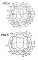
- Fig. 5shows a second embodiment of the present invention.
- the inner and outer teeth profilesare formed so that the leading and trailing edges thereof are basically symmetrical in shape similar to the prior art.
- the external teethare modified by removing part of the trailing surface.
- a flat 20dis ground or otherwise formed on the trailing edge of each tooth.
Landscapes
- Engineering & Computer Science (AREA)
- Mechanical Engineering (AREA)
- General Engineering & Computer Science (AREA)
- Rotary Pumps (AREA)
Description
- The present invention relates generally to automotive lubrication system and more specifically to an oil pump which is suitable for use therein.
- Fig. 1 shows a prior art trochoid type oil pump of the nature disclosed in Utility Model Publication JUM-A-59-88288. In this arrangement a pump casing 1 is formed with crescent shaped induction and
discharge openings inner rotor 5 is mounted on aneccentric drive shaft 4 for synchronous rotation therewith and disposed within a ring shapedouter rotor 6. - In this arrangement the inner rotor is formed with 4 "external"
teeth 7 while the outer rotor is formed with 5 "internal"teeth 8. With this arrangement when thedrive shaft 4 is rotated by a non-illustrated connection with a prime mover such as an internal combustion engine, the inner and outer rotors rotate in unison. Theinner rotor 4 moves within theouter rotor 6 in a manner to definespaces 9 into which oil from theinduction opening 2 can enter and be retained in as they pass of the same. As the rotation of the rotors continues thespaces 9 are sequently moved towards thedischarge opening 3 and the oil which is inducted is subequently compressed and squeezed out therethrough. - However, this arrangement has suffered from the drawback that during the rotation of the teeth of the inner and outer rotors come into mutual contact with one and other and especially in the region of the
discharge opening 3.
Further, as each of thespaces 9 are isolated from one another some of the oil enclosed therein tends to get trapped, and as the pulsation of the pump is extremely large, resonance noise tends to be generated. - In a second prior art arrangement of the nature disclosed in JP-A-57-79290 the oil pump has been constructed so that the teeth on the inner and outer rotors have asymmetrical profiles and wherein the contact ratio is less than 1. However, with this arrangement the curvature of the profile, that is to say, the radius of curvature of the faces and the top land portions of the teeth are extremely limited, and machining of the same requires a large number of intricate operations and precision machining. Even then the contact ratio of the internal and external teeth is less than one, and, in response to minor changes in rotation of the outer rotor, the generation of relatively loud chattering noise is induced.
- A third prior art arrangement is known from reference GB-A-1 316 934 and is disclosed in the preamble of claim 1. Both the internal and the external teeth have asymmetric cross-sections.
- other prior art is disclosed in GB-A-233 423, which relates to a rotary pump or compressor. This compressor comprises an inner and an outer gear, having engaging surfaces of the teeth of each gear formed on continuous and complete epicycloidal and hypocycloidal curves joined together at their respective pitch lines. These gears are eccentrically assembled.
- It is an object of the present invention to provide a gear pump for use in automotive lubrication systems or the like which exhibits smooth low vibration operation and which is readily fabricated.
- This object is achieved by the features of claim 1, especially by the features of its characterizing part.
- In brief, the above object is achieved by a trochoid type gear pump arrangement which features an outer rotor formed with internal teeth and an inner rotor formed with external teeth which can be receivable in the external ones. The profiles of one or both of the internal and external teeth are rendered asymmetric and arranged to engage only in the region of an intake opening formed in the casing in which the two rotors are housed.
- More specifically, the present invention takes the form of a pump which features a casing, the casing having an inlet opening and a discharge opening; an outer rotor rotatably disposed in a recess formed in the casing, the inner rotor being fomed with a plurality of internal teeth, the inner teeth being each defined by a shaped convex recess formed in the inner periphery of the outer rotor, the internal teeth having a leading edge and trailing edge, the leading edge preceeding the trailing edge in the direction of rotation; an inner rotor disposed within the outer rotor, the inner rotor being formed with a plurality of external teeth, the external teeth being defined by shaped convex projections which extend from the outer periphery of the inner rotor, the external teeth having a leading edge and a trailing edge, the internal teeth being receivable in the internal teeth so that the leading edge of the external teeth are engageable with the leading edge of the internal teeth in the region of the inlet opening; and means defining an asymmetry in at least one of the trailing edges of the internal and external teeth.
- According to another aspect of the invention, a fluid pump comprises a casing, the casing having an inlet opening and a discharge opening, an outer rotor rotatably disposed in a recess formed in the casing, the outer rotor being formed with a plurality of internal teeth having a leading edge and trailing edge, the leading edge preceeding the trailing edge in the direction of rotation, the outer rotor being rotatable about a first axis, an inner rotor disposed within the outer rotor, the inner rotor being formed with a plurality of external teeth having a leading edge and a trailing edge, the external teeth being receivable in the internal teeth so that the leading edge of the external teeth are engageable with the leading edge of the internal teeth in the region of the inlet opening, the inner rotor being rotatable about a second axis which is offset from the first axis, and means defining an asymmetry in at least one of the trailing edges of the internal and external teeth.
- According to a further aspect of the invention, a fuild pump comprises a casing, the casing having an inlet opening and a discharge opening, an outer rotor rotatably disposed in a recess formed in the casing, the outer rotor being formed with a plurality of internal teeth having a leading edge and trailing edge, the leading edge preceeding the trailing edge in the direction of rotation, the outer rotor being rotatable about a first axis, an inner rotor disposed within the outer rotor, the inner rotor being formed with a plurality of external teeth having a leading edge and a trailing edge, the inner rotor being rotable about a second axis which is so oriented that the external teeth being receivable in the internal teeth so that the leading edge of the external teeth are engageable with the leading edge of the internal teeth in the region of the inlet opening, and means defining an asymmetry in at least one of the trailing edges of the internal and external teeth.
- The present invention will be understood more fully from the detailed description given herebelow and from the accompanying drawings of the preferred embodiment of the invention, which, however, should not be taken to limit the invention to the specific embodiment but are for explanation and understanding only.
- In the drawings:
- Fig. 1 is a front sectional elevation of the first prior art arrangement discussed in the opening paragraphs of the instant disclosure;
- Fig. 2 is a diagram showing details of the tooth profile which characterizes the present invention;
- Fig. 3 is a side sectional elevation of a first embodiment of the present invention;
- Fig. 4 is a front elevation as seen along along line II - II of Fig. 3;
- Fig. 5 is a front elevation similar to that shown in Fig. 4 which shows a second embodiment of the present invention.
- Figs. 3 and 4 of the drawings show a first embodiment of the present invention. In this arrangement a pump casing 11 is formed with a circular chamber 11a which is closed by a
cover 12. Aneccentric drive shaft 13 is disposed through a bore formed in the casing 11 and arranged to extend into the circular chamber 11a. - The casing 11 is further formed with essentially diametrically located induction and
discharge openings discharge ports cavities 14a and 15a. - Inner and
outer rotors inner rotor 18 is fixed to thedrive shaft 13 for synchronous rotation therewith. - The
outer rotor 19 is arranged to rotate about an axis P1 and theinner rotor 19 is arranged to rotate about an axis P2 which is offset from P1 by an amount "e" (see Fig. 4). Theinner rotor 18 is formed with nine "external"teeth 20 in its outer periphery, whileouter rotor 19 is formed with 10 "internal"teeth 21 about its inner periphery. - The inner and
outer rotors chambers 25 therebetween. - The so called "internal"
teeth 21 of theouter rotor 19 are defined by shaped recesses formed in the inner periphery of theouter rotor 19, and as shown in Fig. 2, are each arranged so that a tooth profile center line X divides each tooth into what shall be referred to as a trailingedge 22 and atop land portion 21a and aleading edge 23 portion. In this instance the leadingedge 23 is defined from the center line in the direction of rotation while the trailing edge is defined from the center line in the direction opposite that of rotation. - Lines Y1 and Y2 are drawn so as to have their origins coincident with the axis P1 and pass through points which lie on the central portions of
convex portions 24 which are located on either side of a tooth. Lines Y1 and Y2 define on included angle "ϑ" therebetween. - The curvature "a" of the trailing
edge 22 is such that the first portion 22a thereof has a radius of curvature R1 the origin of which lies on line Y1, while thesecond portion 22b has a radius ofcurvature R 2 the origin of which lies on the center line X. - The
top land section 21a of the tooth follows from the center line X and blends with a convex portion having a curvature "b". In this instance curvature "b" has a radius of curvature R3 the origin of which lies on line Y2. - As will be understood angle "ϑ" is determined in accordance with the number of the "internal"
teeth 21 formed on the inner rotor. Further, the shape of the "external" teeth is determined in accordance with the development of the "internal" ones. - The aforementioned R1 or R2 can be selected in accordance with the following equation:
2e ≦ R1 or R3 < r

- 2ra x rm · cos ϑ/2 (ra · cos ϑ/2 - rm)
in which ra is a radius of the base circle and rm is a radius of the pitch circle. Normally, R1 and R3 are set equal to each other. However, they can differ from each other as long as the radius rm does not vary. In addition, R2 is free to be selected as long as the curvatures defined by R1 and R3 are connected to each other via the curvature defined by R2. - It will be noted that only the leading edge or
surface 23 having the radius R3 acts as a contact surface and engages the corresponding leadingsurface 20b of theexternal teeth 20 and that, at any one time, only a limited number of surfaces are in actual engagement. - In operation, the above described arrangement is such that when the
drive shaft 13 is rotated in the clockwise direction, theinner rotor 18 is forced to rotate in unison. In the region of theintake opening 14, the leadingsurfaces 20b of theexternal teeth 20 contact the corresponding leadingedges 23 of theinternal teeth 21 and induces theouter rotor 19 to rotate in the same direction. Under these conditions smooth collision free engagement between the teeth on the inner andouter rotors intake opening 14 and a contact ratio of more than 1 is developed. Accordingly, chattering noise and the like is not generated when theouter rotor 19 undergoes slight changes in rotational speed. - Simultaneously, in the induction opening zone, lubricant enters into the
chambers 25 defined between the inner and outer rotors and carried around to the exhaust opening side. As shown in Fig. 4, as eachchamber 25 approaches the wideupstream end 15b of thedischarge opening 15, thetop land sections 20c engage the tops of theconvex sections 24. The leading edge of theexternal teeth 20 is positioned away from the leading edge of theinternal teeth 21 in the region of thedischarge opening 15. Following this, as thechambers 25 approach the narrowdownstream end 15a of the discharge opening, the external teeth begin to deeply enter the internal ones and reduce the volume of thechambers 25. At this time the leadingedges 20b of the external teeth begin to engage the leading edges of the internal teeth, and the volume of thechambers 25 reduces toward zero. - This operation allows the oil in the chambers to be smoothly displaced and prevents any undesirable retention of oil therein from occurring.
Further, as the number of surfaces in actual engagement at any one moment are limited and no collisions between teeth occur with this arrangement, the pump caring vibration which leads to the generation of resonance noise is adequately reduced. - Moreover, as the curvature of the leading and trailing edges of the teeth can be selected relatively freely the production of the above described arrangment is readily produced.
- Fig. 5 shows a second embodiment of the present invention. In this arrangement the inner and outer teeth profiles are formed so that the leading and trailing edges thereof are basically symmetrical in shape similar to the prior art. However, in this embodiment the external teeth are modified by removing part of the trailing surface. In this instance a flat 20d is ground or otherwise formed on the trailing edge of each tooth. Alternatively, as a variation of the second embodiment it is possible to form flats on the corresponding surfaces of the internal teeth in lieu of, or in addition to, the external ones if so desired.
- The operation and effect of this embodiment is essentially similar to the first one.
- While the present invention has been disclosed in terms of the preferred embodiment in order to facilitate better understanding of the invention, it should be appreciated that the invention can be embodied in various ways without departing from the invention set out in the appended claims.


Claims (7)
- A fluid pump comprising:
a casing (12) having an inlet opening (14) and a discharge opening (15),
an outer rotor (19) rotatably disposed in a recess (11a) formed in said casing (12), said outer rotor (19) being formed with a plurality of internal teeth (21) having a leading edge (23) and a trailing edge (22), said leading edge (23) preceding said trailing edge (22) in the direction of rotation, said outer rotor (19) being rotatable about a first axis (P1), and
an inner rotor (18) disposed within said outer rotor (19), said inner rotor (18) being formed with a plurality of external teeth (20) having a leading edge (20b) and a trailing edge, said external teeth (20) being receivable in said internal teeth, said inner rotor (18) being rotatable about a second axis (P2) which is offset (e) from said first axis (P1),
characterized in that
one of said internal and external teeth (21, 20) has an asymmetrical cross-section, so as to allow said internal teeth (21) to engage said external teeth (20) in the region of said inlet opening (14) while allowing said internal teeth (21) to be separated from said external teeth (20) in the region of said discharge opening (15) for establishing fluid communication between chambers (25) defined between adjacent external teeth (20) in the region of said discharge opening (15). - A pump as claimed in claim 1, characterized in that said internal teeth (21) of said outer rotor (19) and said external teeth (20) of said inner rotor (18) are formed in convex-shaped configuration.
- A fluid pump as claimed in claim 1 or 2,
characterized in that
each of said internal teeth (21) is defined by a shaped convex recess formed in the inner periphery (24) of said outer rotor (19), and each of said external teeth (20) is defined by shaped convex projections which extend from the outer periphery of said inner rotor (18). - A pump as claimed in any one of claims 1 to 3,
characterized in that
the trailing edge (22) of each of the internal teeth (21) is profiled so as to have a first convexly curved portion (22a) which has a first radius (R1) of curvature, and a second concavely curved portion (22b) which merges with the first convex one, the second concavely curved portion (22b) having a second radius (R2) of curvature, the origin of the first radius (R1) of curvature falling on a first imaginary line, said first imaginary line (y1) having an origin coincident with said first axis (P1) and which passes through a point on the inner periphery (24) of said outer rotor (19) which defines the beginning of the profile of said inner tooth (21), said second radius (R2) of curvature having an origin which lies on a second imaginary line (X), said second imaginary line (X) having an origin which is coincident with said first axis (P1) and which passes through essentially the mid point of said inner tooth (21); and
the leading edge (23) of each of said internal teeth (21) includes a top land portion (21a) and a third convexly curved portion, said third convexly curved portion having a third radius (R3) of curvature, said third radius (R3) of curvature having an origin which lies on a third imaginary line (y2) which has an origin coincident with said first axis (P1) and which passes through a point on the inner periphery (24) of said outer rotor (19) which defines the end of the profile of said internal tooth (21). - A pump as claimed in claim 4, characterized in that the external teeth (20) of said inner rotor (18) are profiled in a manner which corresponds to that of the inner teeth (21) formed on the inner periphery (24) of said outer rotor (19).
- A pump as claimed in any one of claims 1 to 3, characterized in that said leading and trailing edges (23, 22) of said internal teeth (21) have essentially symmetrical shapes and wherein said asymmetry defining means is defined by a section (21d) of said trailing edge (22) which is removed and an essentially flat surface is defined.
- A pump as claimed in any one of claims 1 to 3, characterized in that said leading and trailing edges of said external teeth (20) have, essentially symmetrical shapes and wherein said asymmetry defining means is defined by a section (20d) of said trailing edge which is removed and an essentially flat surface is defined.
Applications Claiming Priority (2)
| Application Number | Priority Date | Filing Date | Title |
|---|---|---|---|
| JP62187279AJPH0756268B2 (en) | 1987-07-27 | 1987-07-27 | Oil pump |
| JP187279/87 | 1987-07-27 |
Publications (3)
| Publication Number | Publication Date |
|---|---|
| EP0301158A2 EP0301158A2 (en) | 1989-02-01 |
| EP0301158A3 EP0301158A3 (en) | 1989-08-09 |
| EP0301158B1true EP0301158B1 (en) | 1992-10-21 |
Family
ID=16203215
Family Applications (1)
| Application Number | Title | Priority Date | Filing Date |
|---|---|---|---|
| EP88101957AExpired - LifetimeEP0301158B1 (en) | 1987-07-27 | 1988-02-10 | Oil pump |
Country Status (5)
| Country | Link |
|---|---|
| US (1) | US5114325A (en) |
| EP (1) | EP0301158B1 (en) |
| JP (1) | JPH0756268B2 (en) |
| KR (1) | KR940001213B1 (en) |
| DE (1) | DE3875417T2 (en) |
Families Citing this family (20)
| Publication number | Priority date | Publication date | Assignee | Title |
|---|---|---|---|---|
| GB9010686D0 (en)* | 1990-05-12 | 1990-07-04 | Concentric Pumps Ltd | Gerotor pumps |
| US5797732A (en)* | 1993-12-28 | 1998-08-25 | Unisia Jecs Corporation | Variable capacity pump having a pressure responsive relief valve arrangement |
| JPH07324683A (en)* | 1994-05-31 | 1995-12-12 | Unisia Jecs Corp | Oil pump |
| EP0736691B1 (en)* | 1995-04-04 | 1999-11-03 | Societe Techspace Aero | Internal gear pump with radial supply conduits |
| US5944499A (en)* | 1996-05-27 | 1999-08-31 | Unisia Jecs Corporation | Rotor-type pump having a communication passage interconnecting working-fluid chambers |
| US6123533A (en)* | 1997-04-22 | 2000-09-26 | Dana Corporation | Cavitation-free gear pump |
| DE19727887C2 (en)* | 1997-07-01 | 1999-04-15 | Danfoss As | Hydraulic machine |
| US6644947B2 (en) | 2002-03-14 | 2003-11-11 | Tuthill Corporation | Wave tooth gears using identical non-circular conjugating pitch curves |
| PT1540184E (en)* | 2002-06-03 | 2015-08-20 | M & M Technologies Inc | Gear pump |
| FR2844312B1 (en)* | 2002-09-05 | 2006-04-28 | Centre Nat Rech Scient | ROTATING MACHINE WITH CAPSULISM |
| JP4169724B2 (en)* | 2003-07-17 | 2008-10-22 | 株式会社山田製作所 | Trochoid oil pump |
| EP1927752B1 (en) | 2005-09-22 | 2018-09-12 | Aisin Seiki Kabushiki Kaisha | Oil pump rotor |
| CN101627209B (en)* | 2007-03-09 | 2011-11-23 | 爱信精机株式会社 | oil pump rotor |
| US8137085B2 (en)* | 2008-12-18 | 2012-03-20 | Hamilton Sundstrand Corporation | Gear pump with slots in teeth to reduce cavitation |
| US8087913B2 (en)* | 2008-12-22 | 2012-01-03 | Hamilton Sundstrand Corporation | Gear pump with unequal gear teeth on drive and driven gear |
| JP2012219978A (en)* | 2011-04-13 | 2012-11-12 | Asmo Co Ltd | Speed reducer and gear pump |
| US8888474B2 (en)* | 2011-09-08 | 2014-11-18 | Baker Hughes Incorporated | Downhole motors and pumps with asymmetric lobes |
| JP6027343B2 (en)* | 2012-06-01 | 2016-11-16 | 株式会社山田製作所 | Oil pump rotor |
| JP6011297B2 (en)* | 2012-12-11 | 2016-10-19 | 株式会社ジェイテクト | Inscribed gear pump |
| RU2587513C1 (en)* | 2015-05-26 | 2016-06-20 | Михаил Валерьевич Шардаков | Screw hydraulic machine with inclined profile of stator teeth |
Family Cites Families (14)
| Publication number | Priority date | Publication date | Assignee | Title |
|---|---|---|---|---|
| GB233423A (en)* | 1924-02-07 | 1925-05-07 | Hill Compressor & Pump Co Inc | Improvements in or relating to rotary pumps or the like |
| US2434135A (en)* | 1942-12-02 | 1948-01-06 | Eaton Mfg Co | Gear pump structure |
| US2389728A (en)* | 1943-10-14 | 1945-11-27 | Myron F Hill | Elliptical contour for rotor teeth |
| US2696170A (en)* | 1951-10-04 | 1954-12-07 | Hill Myron Francis | Circulating pump |
| US2830542A (en)* | 1953-06-22 | 1958-04-15 | Gen Motors Corp | Fluid pump |
| DE1426751A1 (en)* | 1965-03-04 | 1968-11-21 | Danfoss As | Rotary piston machine |
| US3536426A (en)* | 1968-04-03 | 1970-10-27 | Novelty Tool Co Inc | Gear pump having eccentrically arranged internal and external gears |
| GB1316934A (en)* | 1969-09-19 | 1973-05-16 | Hobourn Eaton Mfg Co Ltd | Rotary pumps and motors of the type incorporating inner and outer lobed members |
| DD115184A1 (en)* | 1974-12-04 | 1975-09-12 | ||
| JPS5248805A (en)* | 1975-10-16 | 1977-04-19 | Komatsu Ltd | Inner contacting fear pump+ motor |
| DE2644531C2 (en)* | 1976-10-01 | 1986-06-12 | Fürstlich Hohenzollernsche Hüttenverwaltung Laucherthal, 7480 Sigmaringen | Hydrostatic gear machine with a pair of trochoid gears |
| DE3026222A1 (en)* | 1980-07-10 | 1982-02-04 | Siegfried Alexander Dipl.-Ing. 7960 Aulendorf Eisenmann | GEAR RING PUMP |
| GB2085969B (en)* | 1980-10-17 | 1984-04-26 | Hobourn Eaton Ltd | Rotary positive-displacement pumps |
| JPS618484A (en)* | 1984-06-22 | 1986-01-16 | Mitsubishi Metal Corp | Internal gear pump |
- 1987
- 1987-07-27JPJP62187279Apatent/JPH0756268B2/ennot_activeExpired - Lifetime
- 1988
- 1988-02-10EPEP88101957Apatent/EP0301158B1/ennot_activeExpired - Lifetime
- 1988-02-10KRKR1019880001243Apatent/KR940001213B1/ennot_activeExpired - Lifetime
- 1988-02-10DEDE8888101957Tpatent/DE3875417T2/ennot_activeExpired - Lifetime
- 1990
- 1990-07-02USUS07/547,590patent/US5114325A/ennot_activeExpired - Lifetime
Also Published As
| Publication number | Publication date |
|---|---|
| EP0301158A2 (en) | 1989-02-01 |
| KR940001213B1 (en) | 1994-02-17 |
| JPH0756268B2 (en) | 1995-06-14 |
| JPS6432083A (en) | 1989-02-02 |
| DE3875417T2 (en) | 1993-03-04 |
| KR890002599A (en) | 1989-04-11 |
| DE3875417D1 (en) | 1992-11-26 |
| US5114325A (en) | 1992-05-19 |
| EP0301158A3 (en) | 1989-08-09 |
Similar Documents
| Publication | Publication Date | Title |
|---|---|---|
| EP0301158B1 (en) | Oil pump | |
| US4801255A (en) | Internal axis single-rotation machine with intermeshing internal and external rotors | |
| EP1662144B1 (en) | Internal gear pump and inner rotor of the pump | |
| CA2611761C (en) | Gear pump with improved inlet port | |
| KR101263037B1 (en) | Crescent gear pump with novel rotor set | |
| EP1927752B1 (en) | Oil pump rotor | |
| US4768934A (en) | Port arrangement for rotary positive displacement blower | |
| EP0079156B1 (en) | Oil pump | |
| US4767296A (en) | Trochoidal toothed oil pump with thin discharge channel communicating with discharge chamber | |
| JPS60153486A (en) | Helical rotor type rotating positive-displacement type machine and rotor thereof | |
| EP2852763B1 (en) | Reduced noise screw machines | |
| US5096398A (en) | Pulse tuned optimized positive displacement porting | |
| EP1921316B1 (en) | Internal gear pump | |
| EP1340914B1 (en) | Internal gear oil pump | |
| US5685704A (en) | Rotary gear pump having asymmetrical convex tooth profiles | |
| JPS61138893A (en) | Trochoidal oil pump | |
| US5658138A (en) | Rotary pump having inner and outer components having abutments and recesses | |
| EP0627041B1 (en) | Screw rotors type machine | |
| JP2805769B2 (en) | Oil pump | |
| JPS6347916B2 (en) | ||
| JP3627119B2 (en) | Multiple gear pump | |
| JPS63117184A (en) | rotary pump |
Legal Events
| Date | Code | Title | Description |
|---|---|---|---|
| PUAI | Public reference made under article 153(3) epc to a published international application that has entered the european phase | Free format text:ORIGINAL CODE: 0009012 | |
| AK | Designated contracting states | Kind code of ref document:A2 Designated state(s):DE FR GB | |
| PUAL | Search report despatched | Free format text:ORIGINAL CODE: 0009013 | |
| AK | Designated contracting states | Kind code of ref document:A3 Designated state(s):DE FR GB | |
| 17P | Request for examination filed | Effective date:19900207 | |
| 17Q | First examination report despatched | Effective date:19901112 | |
| RAP1 | Party data changed (applicant data changed or rights of an application transferred) | Owner name:ATSUGI UNISIA CORPORATION | |
| GRAA | (expected) grant | Free format text:ORIGINAL CODE: 0009210 | |
| AK | Designated contracting states | Kind code of ref document:B1 Designated state(s):DE FR GB | |
| REF | Corresponds to: | Ref document number:3875417 Country of ref document:DE Date of ref document:19921126 | |
| ET | Fr: translation filed | ||
| PLBE | No opposition filed within time limit | Free format text:ORIGINAL CODE: 0009261 | |
| STAA | Information on the status of an ep patent application or granted ep patent | Free format text:STATUS: NO OPPOSITION FILED WITHIN TIME LIMIT | |
| 26N | No opposition filed | ||
| PGFP | Annual fee paid to national office [announced via postgrant information from national office to epo] | Ref country code:GB Payment date:20000121 Year of fee payment:13 | |
| PG25 | Lapsed in a contracting state [announced via postgrant information from national office to epo] | Ref country code:GB Free format text:LAPSE BECAUSE OF NON-PAYMENT OF DUE FEES Effective date:20010210 | |
| GBPC | Gb: european patent ceased through non-payment of renewal fee | Effective date:20010210 | |
| PGFP | Annual fee paid to national office [announced via postgrant information from national office to epo] | Ref country code:FR Payment date:20060220 Year of fee payment:19 | |
| REG | Reference to a national code | Ref country code:FR Ref legal event code:TP Ref country code:FR Ref legal event code:CD | |
| PGFP | Annual fee paid to national office [announced via postgrant information from national office to epo] | Ref country code:DE Payment date:20070208 Year of fee payment:20 | |
| REG | Reference to a national code | Ref country code:FR Ref legal event code:ST Effective date:20071030 | |
| PG25 | Lapsed in a contracting state [announced via postgrant information from national office to epo] | Ref country code:FR Free format text:LAPSE BECAUSE OF NON-PAYMENT OF DUE FEES Effective date:20070228 |