EP0299394B1 - Gas combustion apparatus - Google Patents
Gas combustion apparatusDownload PDFInfo
- Publication number
- EP0299394B1 EP0299394B1EP88111008AEP88111008AEP0299394B1EP 0299394 B1EP0299394 B1EP 0299394B1EP 88111008 AEP88111008 AEP 88111008AEP 88111008 AEP88111008 AEP 88111008AEP 0299394 B1EP0299394 B1EP 0299394B1
- Authority
- EP
- European Patent Office
- Prior art keywords
- burner
- gas
- blowing
- air
- accordance
- Prior art date
- Legal status (The legal status is an assumption and is not a legal conclusion. Google has not performed a legal analysis and makes no representation as to the accuracy of the status listed.)
- Expired - Lifetime
Links
- 238000002485combustion reactionMethods0.000titleclaimsdescription27
- 238000007664blowingMethods0.000claimsdescription58
- 238000010438heat treatmentMethods0.000claimsdescription40
- 238000010304firingMethods0.000claimsdescription12
- 230000000694effectsEffects0.000claimsdescription8
- 238000000638solvent extractionMethods0.000claimsdescription3
- 239000000446fuelSubstances0.000claimsdescription2
- 230000001276controlling effectEffects0.000claims3
- 230000001105regulatory effectEffects0.000claims1
- 239000007789gasSubstances0.000description32
- 238000010411cookingMethods0.000description6
- 238000010276constructionMethods0.000description4
- 239000000567combustion gasSubstances0.000description3
- XLYOFNOQVPJJNP-UHFFFAOYSA-NwaterSubstancesOXLYOFNOQVPJJNP-UHFFFAOYSA-N0.000description3
- 238000010586diagramMethods0.000description2
- 238000000034methodMethods0.000description2
- 230000000630rising effectEffects0.000description2
- 239000000919ceramicSubstances0.000description1
- 230000001419dependent effectEffects0.000description1
- 239000002184metalSubstances0.000description1
- 230000005855radiationEffects0.000description1
- 238000003466weldingMethods0.000description1
Images


Classifications
- F—MECHANICAL ENGINEERING; LIGHTING; HEATING; WEAPONS; BLASTING
- F24—HEATING; RANGES; VENTILATING
- F24C—DOMESTIC STOVES OR RANGES ; DETAILS OF DOMESTIC STOVES OR RANGES, OF GENERAL APPLICATION
- F24C3/00—Stoves or ranges for gaseous fuels
- F24C3/08—Arrangement or mounting of burners
- F—MECHANICAL ENGINEERING; LIGHTING; HEATING; WEAPONS; BLASTING
- F24—HEATING; RANGES; VENTILATING
- F24C—DOMESTIC STOVES OR RANGES ; DETAILS OF DOMESTIC STOVES OR RANGES, OF GENERAL APPLICATION
- F24C3/00—Stoves or ranges for gaseous fuels
- F24C3/08—Arrangement or mounting of burners
- F24C3/085—Arrangement or mounting of burners on ranges
- F24C3/087—Arrangement or mounting of burners on ranges in baking ovens
- F—MECHANICAL ENGINEERING; LIGHTING; HEATING; WEAPONS; BLASTING
- F24—HEATING; RANGES; VENTILATING
- F24C—DOMESTIC STOVES OR RANGES ; DETAILS OF DOMESTIC STOVES OR RANGES, OF GENERAL APPLICATION
- F24C15/00—Details
- F24C15/32—Arrangements of ducts for hot gases, e.g. in or around baking ovens
- F24C15/322—Arrangements of ducts for hot gases, e.g. in or around baking ovens with forced circulation
Definitions
- the inventionrelates to a gas combustion apparatus in a heating chamber comprising a gas burner having substantially horizontal flame ports, and a blowing apparatus for blowing air along the gas flames in order to lengthen it.
- the inventionfurther relates to a gas heating cooker comprising a heating chamber including such a gas combustion apparatus.
- a combustion apparatusin which a blowing apparatus is provided in order to lengthen the flames of a burner. By such a measure, the heat distribution of such a combustion apparatus is more even.
- This known combustion apparatususes a plurality of separate gas burner units and a blowing apparatus which are individually mounted within an elongated baking oven or baking line.
- the gas combustion apparatusis characterized by a bulkhead for partitioning the integral member into the burner member and the blowing member.
- a blowing apparatus 11is provided at the lower portion of a lower burner 8.
- the blowing apparatus 11blows, through the rotation of a fan blade 15' by a fan motor 15 of a blower 14, onto a pipe 13 having numerous air exhaust ports 12 near the lower burner 8 as shown in Fig. 2.
- the hot air of the lower burner 8is carried to the desired far position by the air current blowing off in the horizontal direction from the blowing apparatus 11. Also, the lower vector component is put into the blowing air current to make it possible to carry the hot air much farther.
- blowing apparatus 11were provided at the upper portion of the lower burner 8, combustion gas would be pushed so that it may come to the central portion of the heating chamber.
- the combustion gasis pulled so that it may be brought to the central portion.
- the thermal distribution in a toasting net 6 portionbecomes approximately uniform as shown in Fig. 10 even above or below the lower burner 8.
- the blowing apparatus 11is mounted on the lower portion of the lower burner 8, the temperature of a stock saucer 9 is prevented from rising. Oil falling down from food 5 to be cooked is not evaporated even if the saucer is not filled with water and the oil is not burned. Conventionally, water 10 filled in the saucer causes vapor to dampen the food 5 and to deteriorate the taste.
- the temperature riseis less, with the same effect being provided. Also, when the blowing apparatus 11 is mounted in the upper portion of the lower burner 8, the rising air current of the combustion gas is efficiently controlled, so that the hot current may be positively controlled with less blow amount.
- a burner unit 16 having the lower burner 8 and the blowing apparatus 11 integrally combinedis shown in detail in Fig. 5, Fig. 6, Fig. 8(a), (b), (c). It is composed of a burner member 17 having numerous flame ports 81 arranged in one row or a plurality of rows, a blowing member having numerous air exhaust ports 111 arranged in one row or a plurality of rows, and a bulkhead 19 for partitioning off between the burner member 17 and the blowing member 18.
- a tubular portion which is formed into an approximate H-shape with the burner member 17 and the bulkhead 19, with the burner member 17, the blowing member 18, the bulkhead 19 being formed in an approximate H-shape,is turned into a burner tube 82 into which fuel and primary air flows.
- a gas feed portion 83 having a gas entrance from one way and a mixing tube portion with the primary air sucked with the gasis provided at both the ends of the burner tube 82, a fire transfer flame-port portion 84 is provided at the center, and a heating flame-port portion 85 is provided on both the sides.
- the fire transfer flame portion 84 and the heating flame-port portion 85make the continuous combustion flame.
- a tubular portion which has been formed into an approximate U-shape with the blowing member 18 and the bulkhead 19is turned into an air tube 112 with air being flown therein.
- An air entrance 113which is coupled to the blowing machine 14, a branch portion 114 onto both the sides and an exhaust portion 115 having an air exhaust port 111 on both the sides are provided at the center of the air tube 112.
- a burner member 17, a blowing member 18, a bulkhead 19are integrally engaged by caulking or welding.
- the burner tube 82 and the air tube 112are cut off by the bulkhead 19 respectively into an independent passage.
- a wind direction controlling member 20(not shown in Fig. 5) which is mounted on a blowing member 18 is adapted to regulate the wind direction with respect to the flame of the lower burner 8 so that the hot current may positively reach farther.
- the upper burner 7has a U-shaped opening 72 and a gas entrance 73, which become the combustion face, in the burner lower portion 71.
- the flame ports 75 with the combustion plate 74 composed of metal gauze, ceramic perforated plate or the like being mounted thereonare formed to cover the opening 72.
- the burner upper plate 76has a burner tube 78 mutually communicated with the gas entrance 77 and the combustion plate 74.
- the burner lower plate 71is integrally fixed to the burner upper plate 76, a mixing tube 79 is formed of gas entrances 73, 77, with combustion plate 74 and the burner tube 78 forming the flame port 75 to make the continuous combustion face.
- the front portion of the heating chamber 4may be opened, closed by a door 21, with the rear upper portion of the heating chamber 4 becoming the exhaust port 22.
- Fig. 7is a system diagram showing the construction of a gas heating cooker in one embodiment of the present invention.
- the heat flame-port portion 85 of the lower burner 8 and the flame ports 81 of the fire transfer flame-port portion 84forms the continuous combustion face, furthermore the flame ports 75 form the continuous combustion face as in the upper burner 7, so that a pair of right and left burners of the upper and lower burners 7, 8 are constructed so that the fire may be transferred.
- a firing burner 23is confronted with the combustion face of the upper burner 7 and the lower burner 8 for ignition.
- a firing detector 24 to detect the existence of the ignition and an ignition plug 25are engaged with the firing burner 23.
- a blowing machine 14is connected with the air entrance 113 of the blowing apparatus 11, an electromagnetic valve adapted to open or close the gas is provided on the upper, lower and the firing burners 7, 8, 23.
- the gasis fed from the gas tube 27 through electromagnetic valves 261, 262, 263 corresponding to the respective burner from the main electromagnetic valve 26.
- An operation portion 28is adapted to select in advance and set the heating operation by the upper and lower burners 7, 8.
- the gasis inputted from the operation portion 28, the firing detector 24 by the controlling portion 29. It is outputted through the respective electromagnetic valves 26, 261, 262 and 263.
- a controlling portion 29controls the gas heating cooker.
- Reference character 30refers to a power supply.
- Fig. 10 and 11show the temperature distribution of the toasting net 6 portion by the duty control of the above-described (1). 15 seconds on condition of the blowing machine 14, and 5 seconds off condition are alternately repeated.
- One-dot chain line (A) of the drawingshows the temperature distribution of the off condition in the blow machine, with two-dot chain line (B) being the on condition in the blowing machine 14. They are averaged, showing the temperature distribution of the solid line (C) as the result, so that the uniform thermal distribution is provided.
- a heat shielding plate 31which is shown in Fig. 1, Fig. 3, Fig. 7 is detachably mounted under the toasting net 6 of the heating chamber 4. It is used in the oven for cooking, while it is removed for grill cooking, so that the cooking versatility is widened.
- the upper burner 7 and the lower burner 8are ignited.
- Air flowwhich has horizontal or lower vector components is jetted along the flame directed from the air jetting ports 111 of the blowing apparatus 11 into the horizontal direction of the lower burner 8, so that hot current reaches so far as the lower central portion of the toasting net 6 to heat the entire face with uniform thermal distribution.
- simultaneous heatingis effected from both the upper and lower surfaces forces of the food 5 by the radiation heat from the combustion of the upper burner 7, so that fast and even cooking property is ensured even in a superwide heating chamber 4.
- the wind directionis controlled by the wind direction control member 20 near the blowing apparatus 11, the blow amount of the blowing apparatus 11 is controlled to sequentially move the strong heating portion, thus resulting in uniformed thermal distribution in the superwidened heating chamber 4, which improves much better cooking effect.
- the firemay be positively moved, so that the heating operation may be effected by a burner selected by the operation portion 28, with no risk of raw gas to leak out.
Landscapes
- Engineering & Computer Science (AREA)
- Chemical & Material Sciences (AREA)
- Combustion & Propulsion (AREA)
- Mechanical Engineering (AREA)
- General Engineering & Computer Science (AREA)
- Baking, Grill, Roasting (AREA)
- Gas Burners (AREA)
Description
- The invention relates to a gas combustion apparatus in a heating chamber comprising a gas burner having substantially horizontal flame ports, and a blowing apparatus for blowing air along the gas flames in order to lengthen it. The invention further relates to a gas heating cooker comprising a heating chamber including such a gas combustion apparatus.
- From EP-A-200 626, a combustion apparatus is known in which a blowing apparatus is provided in order to lengthen the flames of a burner. By such a measure, the heat distribution of such a combustion apparatus is more even. This known combustion apparatus uses a plurality of separate gas burner units and a blowing apparatus which are individually mounted within an elongated baking oven or baking line.
- It is an object of the present invention to provide a gas combustion apparatus having a gas burner and a blowing apparatus for blowing air along the gas flames in order to lengthen it, which is of compact construction in order to facilitate its use in a gas heating cooker.
- According to the invention the gas combustion apparatus is characterized by a bulkhead for partitioning the integral member into the burner member and the blowing member.
- Preferable embodiments of the invention are defined in the appended dependent claims.
- The present invention will become clear from the following description taken in conjunction with the preferred embodiments thereof with reference to the accompanying drawings, in which:
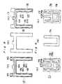
- Fig. 1 is a front-face section view of a heating chamber of a gas heating cooker with a gas combustion apparatus;
- Fig. 2 is a perspective view of a blowing apparatus thereof;
- Fig. 3 is a front-face sectional view of a heating chamber of a gas heating cooker with a combustion apparatus according to the present invention;
- Fig. 4 is a side sectional view of Fig. 3;
- Fig. 5 is a perspective view of a burner unit integrated with a lower burner and a blowing apparatus of the embodiment of Fig. 3;
- Fig. 6 is a partial sectional view in portion A of the burner unit of Fig. 5;
- Fig. 7 is a system diagram showing the construction of a gas heating cooker in the embodiment of Fig. 3;
- Fig. 8 is a plan view of the (a) burner member, (b) bulkhead, (c) blowing member of the exploded lower burner to be used in the gas heating member of the present invention shown in Fig. 3, and the exploded burner unit of the blowing apparatus;
- Fig. 9 is a plan view of the (a) burner lower plate, (b) combustion plate, (c) burner upper plate of the exploded upper burner shown in Fig. 3;
- Fig. 10 is a graph showing the temperature distribution of the toasting net portion; and
- Fig. 11 is a graph showing the temperature distribution of a toasting net portion using a blowing apparatus with the duty control being effected likewise.
- Before the description of the present invention proceeds, it is to be noted that like parts are designated by like reference numerals throughout the accompanying drawings.
- In the gas heating cooker of Fig. 1, a blowing
apparatus 11 is provided at the lower portion of alower burner 8. The blowingapparatus 11 blows, through the rotation of a fan blade 15' by afan motor 15 of ablower 14, onto apipe 13 having numerousair exhaust ports 12 near thelower burner 8 as shown in Fig. 2. The hot air of thelower burner 8 is carried to the desired far position by the air current blowing off in the horizontal direction from the blowingapparatus 11. Also, the lower vector component is put into the blowing air current to make it possible to carry the hot air much farther. - If the blowing
apparatus 11 were provided at the upper portion of thelower burner 8, combustion gas would be pushed so that it may come to the central portion of the heating chamber. When the blowingapparatus 11 is provided at the lower portion of thelower burner 8, the combustion gas is pulled so that it may be brought to the central portion. The thermal distribution in a toasting net 6 portion becomes approximately uniform as shown in Fig. 10 even above or below thelower burner 8. However, when the blowingapparatus 11 is mounted on the lower portion of thelower burner 8, the temperature of astock saucer 9 is prevented from rising. Oil falling down fromfood 5 to be cooked is not evaporated even if the saucer is not filled with water and the oil is not burned. Conventionally,water 10 filled in the saucer causes vapor to dampen thefood 5 and to deteriorate the taste. If thestock saucer 9 is filled withwater 10, the temperature rise is less, with the same effect being provided. Also, when the blowingapparatus 11 is mounted in the upper portion of thelower burner 8, the rising air current of the combustion gas is efficiently controlled, so that the hot current may be positively controlled with less blow amount. - A gas heating cooker of the present invention will now be described with reference to Fig. 3 through Fig. 9.
- The difference in Fig. 3 and Fig. 4 with respect cooker of Fig. 1 is that the
lower burner 8 is integrally combined with the blowingapparatus 11, withflame ports upper burner 7, thelower burner 8 being connected to provide a continuous combustion face. - A
burner unit 16 having thelower burner 8 and the blowingapparatus 11 integrally combined is shown in detail in Fig. 5, Fig. 6, Fig. 8(a), (b), (c). It is composed of aburner member 17 havingnumerous flame ports 81 arranged in one row or a plurality of rows, a blowing member having numerousair exhaust ports 111 arranged in one row or a plurality of rows, and abulkhead 19 for partitioning off between theburner member 17 and the blowingmember 18. A tubular portion which is formed into an approximate H-shape with theburner member 17 and thebulkhead 19, with theburner member 17, the blowingmember 18, thebulkhead 19 being formed in an approximate H-shape, is turned into aburner tube 82 into which fuel and primary air flows. Agas feed portion 83 having a gas entrance from one way and a mixing tube portion with the primary air sucked with the gas is provided at both the ends of theburner tube 82, a fire transfer flame-port portion 84 is provided at the center, and a heating flame-port portion 85 is provided on both the sides. The firetransfer flame portion 84 and the heating flame-port portion 85 make the continuous combustion flame. Also, a tubular portion which has been formed into an approximate U-shape with the blowingmember 18 and thebulkhead 19 is turned into anair tube 112 with air being flown therein. Anair entrance 113 which is coupled to the blowingmachine 14, abranch portion 114 onto both the sides and anexhaust portion 115 having anair exhaust port 111 on both the sides are provided at the center of theair tube 112. Aburner member 17, a blowingmember 18, abulkhead 19 are integrally engaged by caulking or welding. Theburner tube 82 and theair tube 112 are cut off by thebulkhead 19 respectively into an independent passage. A wind direction controlling member 20 (not shown in Fig. 5) which is mounted on a blowingmember 18 is adapted to regulate the wind direction with respect to the flame of thelower burner 8 so that the hot current may positively reach farther. - Also, the similar effect is provided even at the upper portion and the lower portion when the blowing
apparatus 11 of theburner unit 16 is provided near thelower burner 8 as described. - As shown in Fig. 9 (a), (b), (c), the
upper burner 7 has aU-shaped opening 72 and agas entrance 73, which become the combustion face, in the burnerlower portion 71. Theflame ports 75 with thecombustion plate 74 composed of metal gauze, ceramic perforated plate or the like being mounted thereon are formed to cover theopening 72. The burnerupper plate 76 has aburner tube 78 mutually communicated with thegas entrance 77 and thecombustion plate 74. The burnerlower plate 71 is integrally fixed to the burnerupper plate 76, amixing tube 79 is formed ofgas entrances combustion plate 74 and theburner tube 78 forming theflame port 75 to make the continuous combustion face. - The front portion of the
heating chamber 4 may be opened, closed by adoor 21, with the rear upper portion of theheating chamber 4 becoming theexhaust port 22. - Fig. 7 is a system diagram showing the construction of a gas heating cooker in one embodiment of the present invention. As described hereinabove, in a
burner unit 16 integrally provided with thelower burner 8 and the blowingapparatus 11 as described hereinabove, the heat flame-port portion 85 of thelower burner 8 and theflame ports 81 of the fire transfer flame-port portion 84 forms the continuous combustion face, furthermore theflame ports 75 form the continuous combustion face as in theupper burner 7, so that a pair of right and left burners of the upper andlower burners firing burner 23 is confronted with the combustion face of theupper burner 7 and thelower burner 8 for ignition. Afiring detector 24 to detect the existence of the ignition and anignition plug 25 are engaged with thefiring burner 23. - A blowing
machine 14 is connected with theair entrance 113 of the blowingapparatus 11, an electromagnetic valve adapted to open or close the gas is provided on the upper, lower and thefiring burners gas tube 27 throughelectromagnetic valves electromagnetic valve 26. - An
operation portion 28 is adapted to select in advance and set the heating operation by the upper andlower burners operation portion 28, thefiring detector 24 by the controllingportion 29. It is outputted through the respectiveelectromagnetic valves portion 29 controls the gas heating cooker.Reference character 30 refers to a power supply. - When the size, shape, amount and so on of the food to be cooked 5 are varied, and further the applying operation is effected in the
wide heating chamber 4, control of the blow amount of the blowingapparatus 11 and much more effect are provided so that uniform heating for better thermal distribution is provided. The gas burner is operated as follows. - (1) Effect the duty control by the on/off of the blowing
machine 14 with the heating of the central portion being increased during the blowing time, and the strong heating portion is moved from right to left, so that uniform heating is provided. In addition, methods of obtaining the similar effect to that of (1) are as follows. - (2) Control for effecting the blowing operation from one way of the blowing
apparatus 11 so as to effect the alternate operation. - (3) Control for pulsating the blow amount from maximum to minimum.
- (4) Control for adjusting the wind-direction angle of the wind
direction control member 20. Better cooking results are provided even in any control method of the above description. - Fig. 10 and 11 show the temperature distribution of the toasting net 6 portion by the duty control of the above-described (1). 15 seconds on condition of the blowing
machine machine 14. They are averaged, showing the temperature distribution of the solid line (C) as the result, so that the uniform thermal distribution is provided. - A
heat shielding plate 31 which is shown in Fig. 1, Fig. 3, Fig. 7 is detachably mounted under the toastingnet 6 of theheating chamber 4. It is used in the oven for cooking, while it is removed for grill cooking, so that the cooking versatility is widened. - In the construction, the
upper burner 7 and thelower burner 8 are ignited. Air flow which has horizontal or lower vector components is jetted along the flame directed from theair jetting ports 111 of the blowingapparatus 11 into the horizontal direction of thelower burner 8, so that hot current reaches so far as the lower central portion of the toasting net 6 to heat the entire face with uniform thermal distribution. At this time, simultaneous heating is effected from both the upper and lower surfaces forces of thefood 5 by the radiation heat from the combustion of theupper burner 7, so that fast and even cooking property is ensured even in asuperwide heating chamber 4. - The wind direction is controlled by the wind
direction control member 20 near the blowingapparatus 11, the blow amount of the blowingapparatus 11 is controlled to sequentially move the strong heating portion, thus resulting in uniformed thermal distribution in thesuperwidened heating chamber 4, which improves much better cooking effect. - As a
firing burner 23 provided with a firingdetector 24 is confronted with theupper burner 7 and thelower burner 8 with a pair of right and left burners being formed of the continuous combustion face, the fire may be positively moved, so that the heating operation may be effected by a burner selected by theoperation portion 28, with no risk of raw gas to leak out.
Claims (11)
- A gas combustion apparatus in a heating chamber (4) comprising a gas burner (8) having in use subtstantially horizontal flame ports (81), and a blowing apparatus (11) for blowing air along the gas flames in order to lengthen it, whereby the gas burner (8) and the blowing apparatus (11) are formed as an integral unit (16) of a burner member (17) having numerous combustion flame ports (81) arranged in one row or in a plurality of rows, a blowing member (18) having numerous air jetting ports (111) arranged in one row or in a plurality of rows characterized by a bulkhead (19) for partitioning the integral unit (16) into the burner member (17) and the blowing member (18).
- Apparatus according to claim 1,
characterized in that a tubular portion formed by the burner member (17) and the bulkhead (19) is turned into a burner tube (82) through which premixed gas between fuel and primary air flows, and that a tubular portion formed by the bulkhead (19) and blowing member (18) is turned into an air tube (112). - Apparatus in accordance with claim 2,
characterized in that two burner tubes (82) are provided oppositely to each other at a distance and each comprising a gas supply portion (83) and a heating flame-port portion (85) connected with each other, both burner tubes being connected with each other by a fire transfer flame-port portion (84); and the air tube (112) of the blowing member (18) has a branch portion (114) having an air entrance (113) connected with a blowing machine (14) and air jetting portions (115) provided opposite on both sides. - Apparatus in accordance with any of claims 1 to 3,
characterized by a plurality of air jetting ports (111), a wind direction controlling member (20) near the blowing member (18) for regulating the wind direction. - Apparatus in accordance with any of claims 1 to 4,
wherein the air jetting ports (111) of the blowing member (18) are provided under the burner member (17). - Apparatus in accordance with any of claims 1 to 4,
wherein the air jetting ports (111) of the blowing member (18) are disposed above the burner member (17). - Apparatus in accordance with claim 5,
wherein the air blow-off direction of the blowing member (18) has a downward vector component. - A gas heating cooker comprising a heating chamber (4), a gas combustion apparatus according to any preceding claim as a lower gas burner (8), a toasting net (6) having the food (5) to be cooked at a vertically intermediate portion of the heating chamber (4) so as to effect the toasting operation, an upper gas burner (7) provided above the toasting net (6), and the lower gas burner (8) being provided below the toasting net (6).
- Gas heating cooker according to claim 8,
characterized by a firing burner (23) which is confronted with the combustion face of the upper gas burner (7) and the lower gas burner (8) to ignite, a firing detector (24) which is confronted with the firing burner (23) to detect the existence of the ignition, electromagnetic gas valves (261, 262, 263) for turning on/off the gas to be fed to the upper gas burner (7), the lower gas burner (8) and the firing burner (23), an operation board (28) for controlling the heating by the upper gas burner (7) and the lower gas burner (8), a control portion (29) controlled by the operating board (28), the firing detector (24) and controlling electromagnetic gas valves (261, 262, 263) and the blowing machine (14). - Gas heating cooker in accordance with claim 9,
wherein the blowing apparatus is switched on and off with a certain duty cycle in accordance with the output of the control portion (29). - Gas heating cooker in accordance with any of claims 8 to 10,
characterized by a detachable heat shielding plate (31) which can be selectively placed between the toasting net (6) and the lower gas burner (8) for selecting between the functions of an oven and a grill.
Applications Claiming Priority (4)
| Application Number | Priority Date | Filing Date | Title |
|---|---|---|---|
| JP174101/87 | 1987-07-13 | ||
| JP62174101AJP2506791B2 (en) | 1987-07-13 | 1987-07-13 | Gas cooker |
| JP63097080AJPH0718538B2 (en) | 1988-04-20 | 1988-04-20 | Burner equipment |
| JP97080/88 | 1988-04-20 |
Publications (2)
| Publication Number | Publication Date |
|---|---|
| EP0299394A1 EP0299394A1 (en) | 1989-01-18 |
| EP0299394B1true EP0299394B1 (en) | 1992-06-17 |
Family
ID=26438282
Family Applications (1)
| Application Number | Title | Priority Date | Filing Date |
|---|---|---|---|
| EP88111008AExpired - LifetimeEP0299394B1 (en) | 1987-07-13 | 1988-07-09 | Gas combustion apparatus |
Country Status (5)
| Country | Link |
|---|---|
| US (1) | US4901705A (en) |
| EP (1) | EP0299394B1 (en) |
| KR (1) | KR930000929B1 (en) |
| CA (1) | CA1302816C (en) |
| DE (1) | DE3872075T2 (en) |
Families Citing this family (16)
| Publication number | Priority date | Publication date | Assignee | Title |
|---|---|---|---|---|
| US5261388A (en)* | 1992-05-05 | 1993-11-16 | Wright Ivan M | Cooking grill |
| CA2088190C (en)* | 1992-11-05 | 2000-01-11 | Ira Nevin | Pizza oven |
| US5711663A (en)* | 1994-08-14 | 1998-01-27 | Sunbeam Porducts, Inc. | Burner |
| DE20201184U1 (en) | 2002-01-25 | 2002-04-04 | RATIONAL AG, 86899 Landsberg | Burner system with several heat generating devices and cooking device with such a burner system |
| US20060199129A1 (en)* | 2005-03-01 | 2006-09-07 | Foremost Groups, Inc. | Decorative torch for use with pressurized fuel source |
| DE602007010507D1 (en)* | 2006-09-26 | 2010-12-23 | Char Broil Llc | COOKING DEVICE WITH CONKAVEM RADIATOR |
| EP2238388A4 (en)* | 2008-01-18 | 2013-01-09 | Garland Commercial Ind Llc | OPEN LOOP GAS BURNER |
| US20110186038A1 (en)* | 2008-08-01 | 2011-08-04 | Lg Electronics Inc. | Burner And Gas Oven Including The Same |
| KR101073238B1 (en)* | 2009-04-17 | 2011-10-12 | 엘지전자 주식회사 | Burner and cooking appliance |
| KR101620101B1 (en)* | 2009-05-11 | 2016-05-12 | 엘지전자 주식회사 | A cooker |
| EP2333418A1 (en)* | 2009-12-14 | 2011-06-15 | Miele & Cie. KG | Oven and gas burner device, in particular for an oven |
| GB2486489A (en)* | 2010-12-16 | 2012-06-20 | Clay Oven Co Ltd | Grill |
| US20140196713A1 (en)* | 2013-01-15 | 2014-07-17 | General Electric Company | Gas burner assembly for an oven appliance |
| ITBO20130548A1 (en)* | 2013-10-03 | 2015-04-04 | Italforni Pesaro S R L | GAS OVEN |
| US10018363B1 (en)* | 2016-12-23 | 2018-07-10 | Jade Range LLC | Hearth oven |
| US12048394B2 (en) | 2020-09-16 | 2024-07-30 | Haig Levon Gulian | Grill |
Family Cites Families (9)
| Publication number | Priority date | Publication date | Assignee | Title |
|---|---|---|---|---|
| US973498A (en)* | 1909-12-29 | 1910-10-25 | Trenkamp Stove & Mfg Company | Gas-burner. |
| US2607405A (en)* | 1950-10-20 | 1952-08-19 | Surface Combustion Corp | Gas burner having removable port-forming grid |
| US2794497A (en)* | 1955-02-01 | 1957-06-04 | Homer D Dufault | Gas burner |
| US3077826A (en)* | 1959-07-20 | 1963-02-19 | John P Sikorn | Oven |
| US3090373A (en)* | 1960-03-24 | 1963-05-21 | Welbit Corp | Gas fired cooking range |
| US3312271A (en)* | 1964-03-06 | 1967-04-04 | Roper Corp Geo D | Outside pilot arrangement |
| US3340794A (en)* | 1966-03-18 | 1967-09-12 | Giuliano Anthony Philip | Cooking device |
| US3682156A (en)* | 1970-05-14 | 1972-08-08 | Richard L Perl | Gas oven |
| US4615895A (en)* | 1985-04-18 | 1986-10-07 | Nabisco Brands, Inc. | Forced air/gas burner and baking oven incorporating same |
- 1988
- 1988-07-09DEDE8888111008Tpatent/DE3872075T2/ennot_activeExpired - Fee Related
- 1988-07-09EPEP88111008Apatent/EP0299394B1/ennot_activeExpired - Lifetime
- 1988-07-11KRKR1019880008574Apatent/KR930000929B1/ennot_activeExpired - Lifetime
- 1988-07-12CACA000571737Apatent/CA1302816C/ennot_activeExpired - Lifetime
- 1988-07-13USUS07/218,295patent/US4901705A/ennot_activeExpired - Lifetime
Also Published As
| Publication number | Publication date |
|---|---|
| US4901705A (en) | 1990-02-20 |
| EP0299394A1 (en) | 1989-01-18 |
| KR930000929B1 (en) | 1993-02-11 |
| CA1302816C (en) | 1992-06-09 |
| DE3872075T2 (en) | 1993-02-11 |
| DE3872075D1 (en) | 1992-07-23 |
| KR890002613A (en) | 1989-04-11 |
Similar Documents
| Publication | Publication Date | Title |
|---|---|---|
| EP0299394B1 (en) | Gas combustion apparatus | |
| US5909533A (en) | Electric cooking oven with infrared gas broiler | |
| US4403597A (en) | Heat transfer device | |
| US6776151B2 (en) | Positive air flow apparatus for infrared gas broiler | |
| CA1047914A (en) | Gas-fired smooth top range | |
| US5617776A (en) | Induced draft gas fired fryer | |
| EP4000481A1 (en) | Longitudinal burn pot assembly and improved air flow system | |
| US6029653A (en) | Induced draft heat exchanger with serpentine baffles | |
| MXPA00003725A (en) | Venting system for gas oven. | |
| US4648381A (en) | Gas cooking oven | |
| NL1014044C2 (en) | Oven heated by gas burner. | |
| CN1240910A (en) | Electric cooking oven with infrared gas broiler | |
| JPH0774687B2 (en) | Gas combustion device and gas heating cooker | |
| JPH02203114A (en) | Burning device | |
| KR920003238Y1 (en) | Heating apparatus | |
| JP2757516B2 (en) | Gas cooker | |
| KR920008200B1 (en) | Roasting | |
| KR200257613Y1 (en) | Flame hole structure of oven burner for gas oven range | |
| JP2000217718A (en) | Double-sided grill | |
| HUP9904352A2 (en) | Burner shields | |
| JPH01269814A (en) | Burner | |
| JPH04347113A (en) | Gas cooker | |
| MXPA99003263A (en) | Electric cooking oven with infrared gas broiler | |
| HK1028275A (en) | Electric cooking oven with an ultra-red gas grilling device | |
| KR19990026403U (en) | Burner structure of gas cooker |
Legal Events
| Date | Code | Title | Description |
|---|---|---|---|
| PUAI | Public reference made under article 153(3) epc to a published international application that has entered the european phase | Free format text:ORIGINAL CODE: 0009012 | |
| 17P | Request for examination filed | Effective date:19880709 | |
| AK | Designated contracting states | Kind code of ref document:A1 Designated state(s):DE FR GB IT | |
| 17Q | First examination report despatched | Effective date:19900403 | |
| GRAA | (expected) grant | Free format text:ORIGINAL CODE: 0009210 | |
| AK | Designated contracting states | Kind code of ref document:B1 Designated state(s):DE FR GB IT | |
| ITF | It: translation for a ep patent filed | ||
| REF | Corresponds to: | Ref document number:3872075 Country of ref document:DE Date of ref document:19920723 | |
| ET | Fr: translation filed | ||
| PLBE | No opposition filed within time limit | Free format text:ORIGINAL CODE: 0009261 | |
| STAA | Information on the status of an ep patent application or granted ep patent | Free format text:STATUS: NO OPPOSITION FILED WITHIN TIME LIMIT | |
| 26N | No opposition filed | ||
| PGFP | Annual fee paid to national office [announced via postgrant information from national office to epo] | Ref country code:GB Payment date:19950628 Year of fee payment:8 | |
| PGFP | Annual fee paid to national office [announced via postgrant information from national office to epo] | Ref country code:DE Payment date:19950710 Year of fee payment:8 | |
| PGFP | Annual fee paid to national office [announced via postgrant information from national office to epo] | Ref country code:FR Payment date:19950711 Year of fee payment:8 | |
| PG25 | Lapsed in a contracting state [announced via postgrant information from national office to epo] | Ref country code:GB Effective date:19960709 | |
| GBPC | Gb: european patent ceased through non-payment of renewal fee | Effective date:19960709 | |
| PG25 | Lapsed in a contracting state [announced via postgrant information from national office to epo] | Ref country code:FR Effective date:19970328 | |
| PG25 | Lapsed in a contracting state [announced via postgrant information from national office to epo] | Ref country code:DE Effective date:19970402 | |
| REG | Reference to a national code | Ref country code:FR Ref legal event code:ST | |
| PG25 | Lapsed in a contracting state [announced via postgrant information from national office to epo] | Ref country code:IT Free format text:LAPSE BECAUSE OF NON-PAYMENT OF DUE FEES;WARNING: LAPSES OF ITALIAN PATENTS WITH EFFECTIVE DATE BEFORE 2007 MAY HAVE OCCURRED AT ANY TIME BEFORE 2007. THE CORRECT EFFECTIVE DATE MAY BE DIFFERENT FROM THE ONE RECORDED. Effective date:20050709 |