EP0299383A2 - Method of reading identification code sheets - Google Patents
Method of reading identification code sheetsDownload PDFInfo
- Publication number
- EP0299383A2 EP0299383A2EP88110945AEP88110945AEP0299383A2EP 0299383 A2EP0299383 A2EP 0299383A2EP 88110945 AEP88110945 AEP 88110945AEP 88110945 AEP88110945 AEP 88110945AEP 0299383 A2EP0299383 A2EP 0299383A2
- Authority
- EP
- European Patent Office
- Prior art keywords
- identification code
- sub
- areas
- representation
- reading
- Prior art date
- Legal status (The legal status is an assumption and is not a legal conclusion. Google has not performed a legal analysis and makes no representation as to the accuracy of the status listed.)
- Granted
Links
Images


Classifications
- G—PHYSICS
- G06—COMPUTING OR CALCULATING; COUNTING
- G06K—GRAPHICAL DATA READING; PRESENTATION OF DATA; RECORD CARRIERS; HANDLING RECORD CARRIERS
- G06K19/00—Record carriers for use with machines and with at least a part designed to carry digital markings
- G06K19/06—Record carriers for use with machines and with at least a part designed to carry digital markings characterised by the kind of the digital marking, e.g. shape, nature, code
- G06K19/06009—Record carriers for use with machines and with at least a part designed to carry digital markings characterised by the kind of the digital marking, e.g. shape, nature, code with optically detectable marking
- G06K19/06037—Record carriers for use with machines and with at least a part designed to carry digital markings characterised by the kind of the digital marking, e.g. shape, nature, code with optically detectable marking multi-dimensional coding
- G—PHYSICS
- G06—COMPUTING OR CALCULATING; COUNTING
- G06K—GRAPHICAL DATA READING; PRESENTATION OF DATA; RECORD CARRIERS; HANDLING RECORD CARRIERS
- G06K19/00—Record carriers for use with machines and with at least a part designed to carry digital markings
- G06K19/06—Record carriers for use with machines and with at least a part designed to carry digital markings characterised by the kind of the digital marking, e.g. shape, nature, code
- G06K2019/06215—Aspects not covered by other subgroups
- G06K2019/06253—Aspects not covered by other subgroups for a specific application
- G—PHYSICS
- G06—COMPUTING OR CALCULATING; COUNTING
- G06K—GRAPHICAL DATA READING; PRESENTATION OF DATA; RECORD CARRIERS; HANDLING RECORD CARRIERS
- G06K19/00—Record carriers for use with machines and with at least a part designed to carry digital markings
- G06K19/06—Record carriers for use with machines and with at least a part designed to carry digital markings characterised by the kind of the digital marking, e.g. shape, nature, code
- G06K2019/06215—Aspects not covered by other subgroups
- G06K2019/06262—Aspects not covered by other subgroups with target- or other orientation-indicating feature
Definitions
- the inventionrelates, in general, to an identification code sheet and a method of its reading and, more particularly, to an identification code sheet representing a merchandise code, a character string and a document etc. capable of identifying a numerical character, symbol, an alphabet, a Kana-Kanzi character etc., and to a method of its reading enabling reading of the content of identification code from said sheet.
- said bar codeis set up by a plurality of fine and thick bars spaced regularly and combined to represent a numerical character etc.
- a sheet of bar code set up by a combination of a plurality of fine and thick bars spaced regularlyis characteristically accompanied by such drawbacks as a need of high level technics of printing on the sheet and of printing very costly and requiring unnecessarily high level of accuracy for preparation.
- Another sheet of token code type for binary representation in terms of the locations of punched holeis accompanied by such drawbacks as a need of punching process and a low speed of reading relative to an optical and a magnetic types.
- bar codesare to be identified as to binary codes on the principle of finding both a finess/thickness and a location of the code bars, thus often resulting in a high likelihood of inducing reading errors; these types of codes are mostly to represent, in general, the numerical characters and rarely can handle even the reading covering the alphabets. For this reason, the realization of these conventional means has not so far been achieved to cover a Kanzi-code under JIS (Japanese Industrial Standard) rule.
- Primary object of the inventionis a provision of an identification code sheet and a method of its reading, wherein a representation area is defined by both a X-axis and a Y-axis for representation of an identification code, and in said representation area are provided and sub-areas in which said identification code is recorded by means of binary signals.
- a representation area defined by both the X-axis and the Y-axisis represented on an identification code sheet, and needed signal codes are recorded in sub-areas of said representation area, thus providing an identification code.
- an exact reading of signal codescan be attained, without any limitation to the available direction of reading, by virtue of an existence of the representation area, when the identification code is read by means of a senser to read identification codes.
- Another object of the inventionis a provision of an identification sheet and a method of its reading, wherein said representation area is divided into at least sixteen or more sub-areas, and in each of which said identification code set up by signal codes in terms of binary signals is recorded.
- a large number of data of 2 factorialscan be recorded, and any representation in terms of Kana-Kanzi, Thai, Arabic and Chinese letters etc. as well as numerical characters, symbols and alphbets may be provided and read. And representation on a sheet of an ordinary quality can be made and read at a very high level of accuracy and speed, without need for use of a paper of special quality, availing only a printing means represented by such printer of general purpose type designed for a microcomputer etc.
- Another object of the inventionis a provision of an identification code sheet and a method of its reading, wherein sixteen or more sub-areas in said representation area are grouped into four or more assemblies, in which said identification code of 24 or more signal codes is recorded.
- recording and readingcan be had in a large versatility, depending on a proper method applied to the selection of the assemblies, thus ensuring an enlargement of an available recording capacity and an ease with which an improved versatility of grouping into the assemblies and added applicability of converting to cipher as well.
- Still further object of the inventionis a provision of an identification code sheet and a method of its reading, wherein an auxiliary representation area is provided next to the periphery of said representation area and an auxiliary mark for identification of reading a direction of recorded identification code on said auxiliary representation area is recorded.
- This type of embodimentenables a finding of a representation area's leading end position, trailing end position and vertical and lateral directions of reading made by a sensor to read identification codes and simplifies the pasting of an identification code sheet and to carry out an interpretation at an improved accuracy and higher speed.
- Still further object of the inventionis a provision of an identification code sheet and a method of its reading, wherein separation marks are provided between said sub-areas in said representation area in order to be readily interpreted for discrimination.
- sub-areascan be assuredly found by virtue of separation marks to ensure a stabilized interpretation of an identification code, even when there are present an error in printing and an irregularity of the surface of pasting etc.
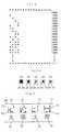
- FIG.1is shown an embodiment of the invention in form of a strip of identification code sheet 10.
- Said identification code sheet 10is a strip of code sheet 12 which may be of either paper or plastic film and the likes.
- an representation area 14on the face of the identification code sheet 12.
- Said representation area 14bears the representation area 20 definded by a X-axis 16 and a Y-axis 18 in form orthogonal coordinates, wherein a signal codes 22 is printed to represent identification codes 21 in said representation area 20.
- Said representation area 20is sub-divided into sixteen sub-areas 24, in each of which a signal code 22 in terms of binary signal codes of 0 or 1 is to be printed; said area 20 may be of various shapes as illustrated in Fig.2.
- Fig.2(a)gives an illustration of the embodiment where a series of signal codes 22 is arranged in a straight line, with length ratio of X-axis 16 to Y-axis 18 of 16:1.
- Fig.2 (b)shows another embodiment where a series of signal codes 22 is arranged in double straight lines, with X-Y axis length ratio of 4:1.
- Fig.2 (c)represents a similar embodiment, with X-Y length ratio of 1:1.
- Figs.2 (d) and (e)give further another embodiment, with X-Y length ratio, contrary to the same of Figs. 2 (a) and (b) of 4:1 and 16:1 respectively, to form a longitudinal elongated shape of sheet.
- the shape of the identification code sheetmay be changed properly to meet a particular need case by case as may be found necessary.
- the sub-areas 24 in the reprensetation area 20are designed, as illustrated in Fig.3, to provide a record of the identification code 21, according to 216 binary codes as represented by 0000, 1000, 2000, ⁇ ⁇ FFFF as illustrated in Fig.4, by arranging P1, P2, P3 ⁇ P16 in a horizontal row and in an appropriate order and addressing them and subsequently making record, in P1, P2, P3 ⁇ P16, of a binary signal of either 0 or 1 as may be found necessary.
- Said binary signal 26 used to print in the individual sub-areas 24may have various shapes as shown in Fig.5.
- Fig.5 (a)is given an example of mark filling up almost totally a sub-area 24 of a rectangular form
- Figs.5 (b), (c), (d) and (e)show other marks of round, star,triangle and four-dot combination form, with a blank left in the periphery of said sub-area 24.
- a suitable printing means of an ordinary typemay be applied, and presently commercially available microcomputor and handy computor or 11- or 24-dot type may also be used for the purpose mentioned.
- name of merchandize, name of section in charge, office address, name of person, telephon number and any other similar character string, message and statement of advertisementmay be converted through the microcomputer, according to JIS rule of coding (or the corresponding similar rule of other countries) and a single representation area 20 of one of 216 signal codes 22 for every character.
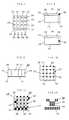
- identification code 21it is preferable to have prior representation of the identification code 21 in terms of a character 28 of Kana-Kanzi, English or some other languages as may be found necessary at a location next to the bottom portion or the likes of the representation area 20 for individual signal codes 22, as illustrated in Fig.6, to facilitate a visual confirmation.
- Thisenables one identification code to be expressed as a single character just equivalent to a single identification code thus providing a clean representation in parallel as shown in Fig.6.
- Fig.7represents another embodiment of the invention, where a signal code 22 of binary type of the sub-area 24 precedingly mentioned is subdivided in such a manner that, as illustrated, P1 ⁇ P4, P5 ⁇ P8, P9 ⁇ P12 and P13 ⁇ P16 are divided into Q1, Q2, Q3, and Q4 groups resprectively, every groups having four elements. Said four groups are then recorded in terms of four assemblies 30, according to this embodiment.
- the method of sub-division of said sixteen sub-areas 24 into total four groups and sequence of arrangement of the signal codes 22 represented in the assemblies 30may be selected as may be found necessary: for example, they may be (P1, P6, P11, P16/ P5, P10, P15, P4 / P9, P14, P3, P8 / P2, P7, P12, P13),(P1, P5, P9, P13,/ P14, P15, P16, P12/ P8, P4, P3, P2 / P6, P10, P11, P7),(P1, P2, P6, P5 / P3, P4, P8, P7 / P11, P12, P16, P15 / P9, P10, P14, P13) etc. and some other types of combination as may be found appropriately.
- a representation area 20is established an auxiliary representation area 36 defined by the extensions 32 and 34 of the X-axis and the Y-axis, as shown is in Fig.8 (a) and (b), represententing an extension of the X-axis 16 and the Y-axis 18, and in a proper location in the said auxiliary area 36, for example the periphery of representation area 20, such as an area diagonal to point of intersection between the X-axis 16 and the Y-axis 18 as illustrated in Fig.8 (a), in order to facilitate the recording an auxiliary mark 38 of a binary signal, as illustrated in Fig.8(b), in the periphery of the representation area 20.
- Said mark 38needs not be limited to the rectangular shape as illustrated in Fig.8 and may have some other shapes, such as round, star, plus, and minus symbols etc., as may be found necessary.
- identification of the reading direction by a senseris made much more ease and interpretation thereby more exact.
- Conventional inventionsare said to involve, in the case of bar code, a failure of reading where reading angle deviates 45° or more away from the standard.
- the embodiment according to the inventionensures stabilized interpretation at a high level of the accuracy, regardless of a directional deviation of pasting of the identification code sheet on the merchandise and the same of reading.
- Fig.9represents another embodiment of the invention, wherein the representation area 20 is sub-divided by horizontal sub-area separation lines 40 and vertical sub-area separation lines 42, with their separation marks 44 prited at regular intervals.
- sub-areas in representation areamay be readily filled up, using a suitable pencil or the likes, to make marks of solid or round etc., and entry of the identification code at the site of operation etc., where the pasting of the identification code sheet and correction of entry having been made can be done with extreme ease, and legiblity may be improved.
- Fig.10is further another embodiment of the invention, according to which the portions of intersection of horizontal sub-area sparation lines 40 with vertical sub-area separation lines 42 in the representation area 20 shown in Fig.9 are identified with separation marks 44 as illustrated.
- a scope of the sub-areacan be known by reading of said separation marks put at every intersection, which, in turn, ensure simplification and speed-up of the separation.
- Fig.11 and Fig.12are practical examples of the embodiment, respectively.
- Fig.11are printed, on the identification code sheet 10, representation areas 20 in form of crossed bars, and signal codes 22 and separation marks 44 in rectangular solid blacks, and in Fig.12 are printed out the dots according to the allotment as illustrated, by means of the microcomputer's printer. Any representation most suitable for a printing means may be made according to the embodiments represented by Fig.11 and Fig. 12.
- the identification code sheethas only to be able to be checked to see the presence of a binary signal code for individual sub-areas of representation areas. This means an applicability of paper of ordinary quality to the make of the said sheet and no need for use of a special paper of unusual cost designed for special application, unlike the case with conventinal type bar code. According to the embodiment of the invention, no problem will be encountered in using the identification code sheet, because of reading a binary signal code in the representation area, defined by both the X-axis, and the Y-axis, although the size of code may vary case by case.
- the identification code sheet mentioned abovemay be applied also to the papers for name card, card, plastic film and the carton's sheet etc. besides the ordinary paper.
- the representation area and the identification codeshould preferably be represented by printing or with magnetic ink, but conventional technics of conventional punch-type signals are in no case excluded from an application to meet the similar need.
- Fig.15, Fig.16 and Fig.17concern an example of the method of reading the identification code sheet 10 according to the invention.
- a reading senser 52such as a bar code reader to read the representation area 20 and signal codes 24 for signal input, followed by subsequent internal processing, result thereof being displayed on an output means 54 of CRT or a printer having been connected as described later.
- said computer 50comprises a means 56 of determining representation areas, a means 58 of determining sub-areas, a means 60 of determining assemblies, a means 62 of detecting presence of binary signals, a means 64 of converting binary codes and a means 66 of converting codes for output means, the circuit thereof being set up by IC, LSI and the likes, respectively.
- Said means 56 of determining representation areasis set up, as illustrated in Fig.16, by a means 68 of determining the X-axis, a means 70 of determining the Y-axis and a means 72 of correcting a direction of X-axis in order to enable the detection of the representation area 20 of the identification code sheet 10 affected by input from the senser 52 to read the identification code, through an interface 74 for reading the data and a means 76 of setting memories.
- Said means 58 of determining sub-areasserves to divide the data having been input according to setting by a means 78 of setting memories or the means 56 of determining representation areas, at a required interval and into a required number of the sections in the direction of both the X-axis, and the Y-axis, and where separation marks 44 are present, to detect the marks 44 being followed by calculation for gaps between the marks and the X-Y axis to enable the division of the representation area 20 into the sub-areas 24 of a number as may be required.
- Said means 60 of determining the assembliesserves to group said sub-areas 24 into the assemblies 30 as required through a means 59 of detecting separation marks and determining sub-areas or the likes, according to setting by the means 78 of setting the memories and combining with address having been stored in a predetermined number of groups of sub-area 24.
- Said means 62 of detecting presence of binary signalsis useful to find presence of binary signal marks 26 when the input proportional to predetermined area of said marks 26 having been input by graphic processing of sub-areas 24 is in a scope as required (for example, in case of an embodiment represented by Fig.12, a total sum corresponding to four to nine dots) and absence of the same when not.
- Said means 64 of converting binary codesserves to determine an identification signal code through interpretation of presence of binary signal marks 26 of individual sub-areas 24, in order to transmit the same to the means 66 of converting code for the output unit.
- 82stands for an interface for the output to the printer and CRT.
- said interpretationis made, in pursuant to a flow chart shown in Fig.17, one by one, to see the X-axis 16, the Y-axis 18 and the auxiliary mark or the marks 38 etc. of the identification code sheet 10 read by said senser 52 through the means 56 of determining the representation areas, thus providing memories in suitable memory areas, in terms of bit image for a transmission of data of one or more as may be found necessary.
- Data having been so transmittedis then graphically processed for a rotation and a movement, depending on a means 72 of correcting a direction of the X-axis, and then allocation of both the sub-areas 24 and the assemblies 30 precedingly mentioned is made by said means 58 of determining sub-areas said means 60 of determining the assemblies respectively, in order to convert binary codes for preparation of a determined format to provide successive transmission to the output unit 54 of CRT or a printer.
- Calculation of extensions of both the X-axis and the Y-axis and auxiliary marksmade availing a graphic analysis, offers a fast determination of a direction of both the X-axis and the Y-axis, enabling graphic reversal or the likes as may be required.
- the embodiment mentionedinvolves a reading of an identification codes of the identification code sheet by properly moving a reading senser such as a bar senser: equivalent reading may be had by use of a surface senser to find a two dimensional size of A4, B5 and B6 etc., for which indvidual representation areas may be determined according a direction of both said X-axis and said Y-axis and location of said auxiliary mark or marks as precedingly mentioned, and a direction of character strings may also be determined, depending on the location and the number of said auxiliary marks.
- a reading sensersuch as a bar senser
- equivalent readingmay be had by use of a surface senser to find a two dimensional size of A4, B5 and B6 etc., for which indvidual representation areas may be determined according a direction of both said X-axis and said Y-axis and location of said auxiliary mark or marks as precedingly mentioned, and a direction of character strings may also be determined, depending on the location and the number of said auxiliary marks.
- readingmay proceed rightwards according to an arrow, and in another case where two auxiliary marks 38 are printed, reading may proceed leftwards according to another arrow, as shown in Figs.18 (a), and (b).
- readingmay proceed downwards according to an arrow, and in further still another case where double auxiliary marks 38 are printed, the reading then proceed upwards according to an arrow, as shown in Figs. 18 (c) and (d).
- the location and the numbers of the auxiliary marksmay also be used as a signal for determining a combination of the sub-areas composing an assembly.
- a disposition of gaps 86, both vertical and horizontal, to between said sub-areas 24 in the representation area 20enables a clear distinction of said sub-areas 24 from both the X-axis 16 and the Y-axis 18 and operation of said representation area 20 at an improved level of accuracy, even if binary signal marks 26 of black solid dot have been put both horizontally and vertically, in all the sub-areas 24 arranged, the marks 44 and said binary signal marks 26 then being discontinuous, thus demonstrating a substantial preferability for accurate operation.
- Fig.19 (a)represents an embodiment of the invention where gaps 86 are located next to both the X-axis 16 and Y-axis 18 mentioned as illustrated in Fig.19(b), and said gaps 86 may be located in between the sub-areas 24 and further be used for instruction of direction of reading a character string or for the same of combination of the sub-areas setting up an assembly, by use of gaps as a signal in place of an auxiliary mark or marks, through a proper change of the location and numbers of said gaps 86.
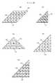
- binary codesmay be printed, in a single representation area, for a plurality of Kana-Kanzi letters, by interposing a split for every 2 n sub-areas as shown in Fig.19 (c).
- the X-axis and the Y-axisare arranged in mutual orthgonality, but they may be disposed intersected at a suitable angle as exampled in Figs.20 (a), (b), (c) and (d), and moreover they may have any shapes other than a rectangle.
Landscapes
- Physics & Mathematics (AREA)
- General Physics & Mathematics (AREA)
- Engineering & Computer Science (AREA)
- Theoretical Computer Science (AREA)
- Inspection Of Paper Currency And Valuable Securities (AREA)
- Record Information Processing For Printing (AREA)
- Credit Cards Or The Like (AREA)
- Character Discrimination (AREA)
Abstract
Description
- The invention relates, in general, to an identification code sheet and a method of its reading and, more particularly, to an identification code sheet representing a merchandise code, a character string and a document etc. capable of identifying a numerical character, symbol, an alphabet, a Kana-Kanzi character etc., and to a method of its reading enabling reading of the content of identification code from said sheet.
- Of identification code sheets involved in an identification, there are known a bar code and a token code designed to represent a numerical character and/or a symbol.
- As well known, said bar code is set up by a plurality of fine and thick bars spaced regularly and combined to represent a numerical character etc. According to the prior art, a sheet of bar code set up by a combination of a plurality of fine and thick bars spaced regularly is characteristically accompanied by such drawbacks as a need of high level technics of printing on the sheet and of printing very costly and requiring unnecessarily high level of accuracy for preparation.
- Another sheet of token code type for binary representation in terms of the locations of punched hole is accompanied by such drawbacks as a need of punching process and a low speed of reading relative to an optical and a magnetic types.
- Other drawbacks inherent to the said types of sheet are presently a limited capability of representing only a numerical character and a part of a character string, and a need of re-making whenever an urgent change of the code content is needed to be made by the operators by code printer or a punch installed elsewhere away from the site of operation, meaning a substantial difficulties encountered alsoin the data maintenace, especially for a large scale POS (Point of Sales system).
- There is also another known art represented by reading means to handle an identification code represented by a bar code system, according to U.S. Patent Application No. 316,936 (Japanese Patent Publication No. 21980 of 1978).
- According to said prior arts, bar codes are to be identified as to binary codes on the principle of finding both a finess/thickness and a location of the code bars, thus often resulting in a high likelihood of inducing reading errors; these types of codes are mostly to represent, in general, the numerical characters and rarely can handle even the reading covering the alphabets. For this reason, the realization of these conventional means has not so far been achieved to cover a Kanzi-code under JIS (Japanese Industrial Standard) rule. According to the said conventional art, there is also an absolute need for an exact reading of a finess/thickness and a location of the bars setting up bar codes, which means a likelihood of reading errors to occur, depending on misprints of the code bars, elongation/shrinkage of the bar code papers, irregularity of the surfaces on which the bar code papers are to be pasted and a change in the reading angle of a senser relative to the bar code paper.
- More recently a new method of code-making is being developed, by which O to F is represented by coding properly "" character. It should, however, be noted that "
 " character involves, in coding thereof, such unsolved problems as a need for addition thereto of a direction of reading and specification of the same, because of the symmetrical composition of said character in both horizontal and vertical directions.
- Primary object of the invention is a provision of an identification code sheet and a method of its reading, wherein a representation area is defined by both a X-axis and a Y-axis for representation of an identification code, and in said representation area are provided and sub-areas in which said identification code is recorded by means of binary signals. According to the embodiment of the invention, a representation area defined by both the X-axis and the Y-axis is represented on an identification code sheet, and needed signal codes are recorded in sub-areas of said representation area, thus providing an identification code. In this manner, an exact reading of signal codes can be attained, without any limitation to the available direction of reading, by virtue of an existence of the representation area, when the identification code is read by means of a senser to read identification codes.
- Another object of the invention is a provision of an identification sheet and a method of its reading, wherein said representation area is divided into at least sixteen or more sub-areas, and in each of which said identification code set up by signal codes in terms of binary signals is recorded. According to the embodiment of the invention, a large number of data of 2 factorials can be recorded, and any representation in terms of Kana-Kanzi, Thai, Arabic and Chinese letters etc. as well as numerical characters, symbols and alphbets may be provided and read. And representation on a sheet of an ordinary quality can be made and read at a very high level of accuracy and speed, without need for use of a paper of special quality, availing only a printing means represented by such printer of general purpose type designed for a microcomputer etc.
- Further another object of the invention is a provision of an identification code sheet and a method of its reading, wherein sixteen or more sub-areas in said representation area are grouped into four or more assemblies, in which said identification code of 2⁴ or more signal codes is recorded. According to the embodiment of the invention, recording and reading can be had in a large versatility, depending on a proper method applied to the selection of the assemblies, thus ensuring an enlargement of an available recording capacity and an ease with which an improved versatility of grouping into the assemblies and added applicability of converting to cipher as well.
- Still further object of the invention is a provision of an identification code sheet and a method of its reading, wherein an auxiliary representation area is provided next to the periphery of said representation area and an auxiliary mark for identification of reading a direction of recorded identification code on said auxiliary representation area is recorded. This type of embodiment enables a finding of a representation area's leading end position, trailing end position and vertical and lateral directions of reading made by a sensor to read identification codes and simplifies the pasting of an identification code sheet and to carry out an interpretation at an improved accuracy and higher speed.
- Still further object of the invention is a provision of an identification code sheet and a method of its reading, wherein separation marks are provided between said sub-areas in said representation area in order to be readily interpreted for discrimination. According to the embodiment, sub-areas can be assuredly found by virtue of separation marks to ensure a stabilized interpretation of an identification code, even when there are present an error in printing and an irregularity of the surface of pasting etc.
- Further objects and advantages of the present invention will be apparent from the following description, reference being made to the accompanying drawings wherein preferred embodiments of the present invention are clearly shown.
- Fig.1 is a plan view of an identification code sheet representing an embodiment of the invention, with partial cut-away;
- Figs.2 (a), (b), (c), (d) and (e) are plan views showing variations of the embodiments of the invention, related to a representation area in the code sheet described above;
- Fig.3 is a view illustrating sub-area and the assemblies of the invention, related to the representation area described above;
- Fig.4 is a view illustrating a pattern of coding showing the number and the location of the sub-area where binary code marks exist relative to binary codes;
- Figs.5 (a), (b), (c), (d) and (e) are detail views showing a concept of the embodied binary signal mark respectively of the invention;
- Fig.6 is a plan view of an identification code sheet comprising the characters mentioned, with partial cut-away;
- Fig.7 shows a concept of assemblies representing grouped sub-areas,
- Figs.8 (a) and (b) are illustrations of a representation area having an auxiliary mark according to another embodiment for the identification code sheet;
- Fig.9 shows a concept of a respresentation area having separation lines according to another embodiment;
- Fig.10 is an illustration of representation area comprising separation marks, according to a still further embodiment of the invention;
- Fig.11 and Fig.12 show diagrams wherein the binary code marks are included;
- Fig.13 and Fig.14 give the patterns enabling establishment of both the sub-areas and assemblies of the representing area;
- Fig.15 and Fig.16 show a block diagram illustrating a method of reading an identification code sheet according to the invention;
- Fig. 17 is a flow chart showing a method of reading the identification code sheet according to the invention;
- Figs.18 (a), (b), (c) and (d) show concepts of an arrangement of the auxiliary mark or marks of another embodiment of the representation area according to the invention;
- Figs.19 (a), (b) and (c) give concepts of further another embodiment of the representation area having gaps according to the invention; and
- Figs.20 (a), (b), (c) and (d) show various embodiments where the X-axis and the Y-axis are arranged skew relative to each other, representing still further another embodiment of the invention.
- There follows the detailed description of the preferred embodiments of the invention relative to the accompanying drawings, wherein the numerals in the different views identify identical parts.
- In Fig.1, is shown an embodiment of the invention in form of a strip of
identification code sheet 10. Saididentification code sheet 10 is a strip ofcode sheet 12 which may be of either paper or plastic film and the likes. In the center zone of said strip is printed anrepresentation area 14 on the face of theidentification code sheet 12.Said representation area 14 bears therepresentation area 20 definded by aX-axis 16 and a Y-axis 18 in form orthogonal coordinates, wherein asignal codes 22 is printed to representidentification codes 21 in saidrepresentation area 20. Said representation area 20 is sub-divided into sixteen sub-areas 24, in each of which asignal code 22 in terms of binary signal codes of 0 or 1 is to be printed; saidarea 20 may be of various shapes as illustrated in Fig.2. Fig.2(a) gives an illustration of the embodiment where a series ofsignal codes 22 is arranged in a straight line, with length ratio ofX-axis 16 to Y-axis 18 of 16:1.- Fig.2 (b) shows another embodiment where a series of
signal codes 22 is arranged in double straight lines, with X-Y axis length ratio of 4:1. Fig.2 (c) represents a similar embodiment, with X-Y length ratio of 1:1. Figs.2 (d) and (e) give further another embodiment, with X-Y length ratio, contrary to the same of Figs. 2 (a) and (b) of 4:1 and 16:1 respectively, to form a longitudinal elongated shape of sheet. The shape of the identification code sheet may be changed properly to meet a particular need case by case as may be found necessary. - The sub-areas 24 in the
reprensetation area 20 are designed, as illustrated in Fig.3, to provide a record of theidentification code 21, according to 2¹⁶ binary codes as represented by 0000, 1000, 2000, ·· · FFFF as illustrated in Fig.4, by arranging P₁, P₂, P₃ ··· P₁₆ in a horizontal row and in an appropriate order and addressing them and subsequently making record, in P₁, P₂, P₃ ··· P₁₆, of a binary signal of either 0 or 1 as may be found necessary. Saidbinary signal 26 used to print in the individual sub-areas 24 may have various shapes as shown in Fig.5. In Fig.5 (a) is given an example of mark filling up almost totally asub-area 24 of a rectangular form, while Figs.5 (b), (c), (d) and (e) show other marks of round, star,triangle and four-dot combination form, with a blank left in the periphery of saidsub-area 24. - To representation of the
representation area 20 and/or thesignal code 22 on theidentification sheet 10 mentioned precedingly, a suitable printing means of an ordinary type may be applied, and presently commercially available microcomputor and handy computor or 11- or 24-dot type may also be used for the purpose mentioned. For printing, name of merchandize, name of section in charge, office address, name of person, telephon number and any other similar character string, message and statement of advertisement may be converted through the microcomputer, according to JIS rule of coding (or the corresponding similar rule of other countries) and asingle representation area 20 of one of 2¹⁶signal codes 22 for every character. For this, it is preferable to have prior representation of theidentification code 21 in terms of acharacter 28 of Kana-Kanzi, English or some other languages as may be found necessary at a location next to the bottom portion or the likes of therepresentation area 20 forindividual signal codes 22, as illustrated in Fig.6, to facilitate a visual confirmation. This enables one identification code to be expressed as a single character just equivalent to a single identification code thus providing a clean representation in parallel as shown in Fig.6. - Fig.7 represents another embodiment of the invention, where a
signal code 22 of binary type of the sub-area 24 precedingly mentioned is subdivided in such a manner that, as illustrated, P₁ ∼ P₄, P₅ ∼ P₈, P₉ ∼ P₁₂ and P₁₃ ∼ P₁₆ are divided into Q₁, Q₂, Q₃, and Q₄ groups resprectively, every groups having four elements. Said four groups are then recorded in terms of fourassemblies 30, according to this embodiment. The method of sub-division of said sixteen sub-areas 24 into total four groups and sequence of arrangement of thesignal codes 22 represented in theassemblies 30 may be selected as may be found necessary: for example, they may be (P₁, P₆, P₁₁, P₁₆/ P₅, P₁₀, P₁₅, P₄ / P₉, P₁₄, P₃, P₈ / P₂, P₇, P₁₂, P₁₃),(P₁, P₅, P₉, P₁₃,/ P₁₄, P₁₅, P₁₆, P₁₂/ P₈, P₄, P₃, P₂ / P₆, P₁₀, P₁₁, P₇),(P₁, P₂, P₆, P₅ / P₃, P₄, P₈, P₇ / P₁₁, P₁₂, P₁₆, P₁₅ / P₉, P₁₀, P₁₄, P₁₃) etc. and some other types of combination as may be found appropriately. - The selection of individual addresses of sixteen sub-areas 24 or P₁, P₂, ···, P₁₆ and the same of another sub-areas 24 to be choiced for individual groups Q₁, Q₂, Q₃, and Q₄ of the
assemblies 30 permits a easier addition of cost information to the code of merchandise and ciphered expression of various cards and passwords etc., by changing properly through a microcomputer. - It is also to be noted that, in a
representation area 20, is established anauxiliary representation area 36 defined by theextensions X-axis 16 and the Y-axis 18, and in a proper location in the saidauxiliary area 36, for example the periphery ofrepresentation area 20, such as an area diagonal to point of intersection between the X-axis 16 and the Y-axis 18 as illustrated in Fig.8 (a), in order to facilitate the recording anauxiliary mark 38 of a binary signal, as illustrated in Fig.8(b), in the periphery of therepresentation area 20. Saidmark 38 needs not be limited to the rectangular shape as illustrated in Fig.8 and may have some other shapes, such as round, star, plus, and minus symbols etc., as may be found necessary. - According to the embodiment stated above, identification of the reading direction by a senser is made much more ease and interpretation thereby more exact. Conventional inventions are said to involve, in the case of bar code, a failure of reading where reading angle deviates 45° or more away from the standard. Unlike this, the embodiment according to the invention ensures stabilized interpretation at a high level of the accuracy, regardless of a directional deviation of pasting of the identification code sheet on the merchandise and the same of reading.
- Fig.9 represents another embodiment of the invention, wherein the
representation area 20 is sub-divided by horizontalsub-area separation lines 40 and verticalsub-area separation lines 42, with theirseparation marks 44 prited at regular intervals. - According to the embodiment mentioned above, sub-areas in representation area may be readily filled up, using a suitable pencil or the likes, to make marks of solid or round etc., and entry of the identification code at the site of operation etc., where the pasting of the identification code sheet and correction of entry having been made can be done with extreme ease, and legiblity may be improved.
- Fig.10 is further another embodiment of the invention, according to which the portions of intersection of horizontal
sub-area sparation lines 40 with verticalsub-area separation lines 42 in therepresentation area 20 shown in Fig.9 are identified with separation marks 44 as illustrated. - According to the embodiment represented by Fig.10, a scope of the sub-area can be known by reading of said separation marks put at every intersection, which, in turn, ensure simplification and speed-up of the separation.
- Fig.11 and Fig.12 are practical examples of the embodiment, respectively. In Fig.11 are printed, on the
identification code sheet 10,representation areas 20 in form of crossed bars, and signalcodes 22 and separation marks 44 in rectangular solid blacks, and in Fig.12 are printed out the dots according to the allotment as illustrated, by means of the microcomputer's printer. Any representation most suitable for a printing means may be made according to the embodiments represented by Fig.11 and Fig. 12. - For the foregoing embodiments, descriptions having been made relate only to sixteen
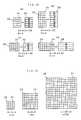
sub-areas 24 of therepresentation area 20. Non the less, they are applicable, as may be found necessary, also to the sub-areas of twenty or thirty-two etc. which are multiples of four as represented in Figs.13 (a) and (b), or saidsub-areas 24 of five, six, seven ··· etc. for everyassemblies 30 as illustrated in Figs.13 (c) and (d). - It is also achievable, with embodiments stated above, to provide the numbers of sub-areas as integer multiples of sixteen and the sames of the assemblies as integer multiples of four (or sames of groups as integer multiples of four). Assuming that the number of the sub-areas is 2n and n is equal to five, or the same of the sub-areas is 2⁵ =32, the characters can then be expressed, for a single identification code, in terms of combinations of 0000, ····· VVVV, or 2³² = 4.292968 x 10⁹ which means a substantial rise in the coverage of the applicable number of the different characters. Furthermore, with n = 6, 7, ···, the coverage of the applicable numbers of the characters different by a single identification code then becomes 22n which means a drastic expantion of the coverage mentioned in exponential function.
- It is also achievable, with the said embodiment applied and the number of the assemblies expressed by 2n-m, to expand exponential-functionally the number of the assemblies by raising m, according to a rise of n. For the embodiments described, sub-areas are divided into four groups, with n = 4 and m = 2. With n = 5, for m = 2 (2²=4), m =3 (2³ =8), division into eight groups, besides four groups, may also be had. Where the number of sub- areas is sixty four, with n = 6, division into sixteen groups may also be made, with m =4 (2⁴ =16), besides mentioned eight and/or sixteen groups, according to the embodiment represented by Fig.14.
- According to the identification code which the invention concerns, encoding may be had to cover the characters as many as 2¹⁶=65536, even with a low n number of only four, but presently JIS rule Kana-Kanzi codes cover only a small amount of the order of about 7,700 characters, so that it may be reasonably claimed that the embodiments mentioned have an sufficient enough capacity of encoding the speech symbols of Thai, Arabic, Chinese characters etc. and even the same of speech synthesis which have not yet been encoded, for the purpose of register and representation.
- For the embodiments described, the identification code sheet has only to be able to be checked to see the presence of a binary signal code for individual sub-areas of representation areas. This means an applicability of paper of ordinary quality to the make of the said sheet and no need for use of a special paper of unusual cost designed for special application, unlike the case with conventinal type bar code. According to the embodiment of the invention, no problem will be encountered in using the identification code sheet, because of reading a binary signal code in the representation area, defined by both the X-axis, and the Y-axis, although the size of code may vary case by case.
- The identification code sheet mentioned above may be applied also to the papers for name card, card, plastic film and the carton's sheet etc. besides the ordinary paper.
- The embodiment stated precedingly involves the representation area and/or signal codes to be printed visibly on a paper, a film and a carbon's sheet etc., sometimes with transparent magnetic ink used. Printing made overlapping a prior printing of ordinary type enables the identification code readable as if reading were made for a plain print.
- As noted, the representation area and the identification code should preferably be represented by printing or with magnetic ink, but conventional technics of conventional punch-type signals are in no case excluded from an application to meet the similar need.
- Fig.15, Fig.16 and Fig.17 concern an example of the method of reading the
identification code sheet 10 according to the invention. - To a
microcomputer 50, as shown in Fig.15 and Fig.16, is connected a readingsenser 52 such as a bar code reader to read therepresentation area 20 andsignal codes 24 for signal input, followed by subsequent internal processing, result thereof being displayed on an output means 54 of CRT or a printer having been connected as described later. As illustrated, saidcomputer 50 comprises ameans 56 of determining representation areas, ameans 58 of determining sub-areas, ameans 60 of determining assemblies, ameans 62 of detecting presence of binary signals, ameans 64 of converting binary codes and ameans 66 of converting codes for output means, the circuit thereof being set up by IC, LSI and the likes, respectively. - Said means 56 of determining representation areas is set up, as illustrated in Fig.16, by a
means 68 of determining the X-axis, ameans 70 of determining the Y-axis and ameans 72 of correcting a direction of X-axis in order to enable the detection of therepresentation area 20 of theidentification code sheet 10 affected by input from thesenser 52 to read the identification code, through aninterface 74 for reading the data and ameans 76 of setting memories. - Said means 58 of determining sub-areas serves to divide the data having been input according to setting by a
means 78 of setting memories or themeans 56 of determining representation areas, at a required interval and into a required number of the sections in the direction of both the X-axis, and the Y-axis, and where separation marks 44 are present, to detect themarks 44 being followed by calculation for gaps between the marks and the X-Y axis to enable the division of therepresentation area 20 into the sub-areas 24 of a number as may be required. - Said means 60 of determining the assemblies serves to group said sub-areas 24 into the
assemblies 30 as required through ameans 59 of detecting separation marks and determining sub-areas or the likes, according to setting by themeans 78 of setting the memories and combining with address having been stored in a predetermined number of groups ofsub-area 24. - Said means 62 of detecting presence of binary signals is useful to find presence of binary signal marks 26 when the input proportional to predetermined area of said
marks 26 having been input by graphic processing ofsub-areas 24 is in a scope as required (for example, in case of an embodiment represented by Fig.12, a total sum corresponding to four to nine dots) and absence of the same when not. - Said means 64 of converting binary codes serves to determine an identification signal code through interpretation of presence of binary signal marks 26 of individual sub-areas 24, in order to transmit the same to the
means 66 of converting code for the output unit. 82 stands for an interface for the output to the printer and CRT. - According to a manner described above, said interpretation is made, in pursuant to a flow chart shown in Fig.17, one by one, to see the
X-axis 16, the Y-axis 18 and the auxiliary mark or themarks 38 etc. of theidentification code sheet 10 read by saidsenser 52 through themeans 56 of determining the representation areas, thus providing memories in suitable memory areas, in terms of bit image for a transmission of data of one or more as may be found necessary. Data having been so transmitted is then graphically processed for a rotation and a movement, depending on ameans 72 of correcting a direction of the X-axis, and then allocation of both the sub-areas 24 and theassemblies 30 precedingly mentioned is made by said means 58 of determining sub-areas said means 60 of determining the assemblies respectively, in order to convert binary codes for preparation of a determined format to provide successive transmission to theoutput unit 54 of CRT or a printer. Calculation of extensions of both the X-axis and the Y-axis and auxiliary marks, made availing a graphic analysis, offers a fast determination of a direction of both the X-axis and the Y-axis, enabling graphic reversal or the likes as may be required. - The embodiment mentioned involves a reading of an identification codes of the identification code sheet by properly moving a reading senser such as a bar senser: equivalent reading may be had by use of a surface senser to find a two dimensional size of A4, B5 and B6 etc., for which indvidual representation areas may be determined according a direction of both said X-axis and said Y-axis and location of said auxiliary mark or marks as precedingly mentioned, and a direction of character strings may also be determined, depending on the location and the number of said auxiliary marks. For example, in case where, in the pheriphery of the Y-
axis 18 of therepresentation area 20, is provided a singleauxiliary mark 38, reading may proceed rightwards according to an arrow, and in another case where twoauxiliary marks 38 are printed, reading may proceed leftwards according to another arrow, as shown in Figs.18 (a), and (b). And is still another case where, depending on theX-axis 16 ofrepresentation area 20, is printed the singleauxiliary work 38, reading may proceed downwards according to an arrow, and in further still another case where doubleauxiliary marks 38 are printed, the reading then proceed upwards according to an arrow, as shown in Figs. 18 (c) and (d). - The location and the numbers of the auxiliary marks may also be used as a signal for determining a combination of the sub-areas composing an assembly.
- Furthermore, as illustrated in Figs.19 (a) and (b), a disposition of
gaps 86, both vertical and horizontal, to between said sub-areas 24 in therepresentation area 20 enables a clear distinction of said sub-areas 24 from both the X-axis 16 and the Y-axis 18 and operation of saidrepresentation area 20 at an improved level of accuracy, even if binary signal marks 26 of black solid dot have been put both horizontally and vertically, in all the sub-areas 24 arranged, themarks 44 and said binary signal marks 26 then being discontinuous, thus demonstrating a substantial preferability for accurate operation. - It should, however, be noted that it is possible to cause discrimination of a straight line of a series of said binary signal marks 26 from both axes X and Y, by interposing
gaps 86 of blank area between the X-axis 16 and the sub-area 24 next thereto and between the Y-axis 18 and said sub-areas 24 next thereto, and that an intermitent disposition of saidgaps 86 of blank area as illustrated in Fig.19 ensures both good result of finding, at an increased accuracy and simplicity in interpretation of the representation area at an improved ease. - Fig.19 (a) represents an embodiment of the invention where
gaps 86 are located next to both the X-axis 16 and Y-axis 18 mentioned as illustrated in Fig.19(b), and saidgaps 86 may be located in between the sub-areas 24 and further be used for instruction of direction of reading a character string or for the same of combination of the sub-areas setting up an assembly, by use of gaps as a signal in place of an auxiliary mark or marks, through a proper change of the location and numbers of saidgaps 86. Further, binary codes may be printed, in a single representation area, for a plurality of Kana-Kanzi letters, by interposing a split for every 2n sub-areas as shown in Fig.19 (c). - In the embodiments described, the X-axis and the Y-axis are arranged in mutual orthgonality, but they may be disposed intersected at a suitable angle as exampled in Figs.20 (a), (b), (c) and (d), and moreover they may have any shapes other than a rectangle.
- All the embodiments described precedingly concern a processing in form of a single task to perform a computer proccessing, but may also ensure a higher speed of input of a senser output to memory areas, the operation and the output in a multitask system.
- Various embodiments have been described precedingly merely to aid the understanding of the invention, and variations may be made by one skilled in the art without departing from the spirit and the essential features of the invention, being not limited to the specific embodiments mentioned.


Claims (10)
Applications Claiming Priority (4)
| Application Number | Priority Date | Filing Date | Title |
|---|---|---|---|
| JP173352/87 | 1987-07-11 | ||
| JP62173352AJPS6486289A (en) | 1987-07-11 | 1987-07-11 | Identifying code paper |
| JP232983/87 | 1987-09-17 | ||
| JP62232983AJPH0821054B2 (en) | 1987-09-17 | 1987-09-17 | Identification code reader |
Publications (3)
| Publication Number | Publication Date |
|---|---|
| EP0299383A2true EP0299383A2 (en) | 1989-01-18 |
| EP0299383A3 EP0299383A3 (en) | 1991-03-20 |
| EP0299383B1 EP0299383B1 (en) | 1994-11-23 |
Family
ID=26495361
Family Applications (1)
| Application Number | Title | Priority Date | Filing Date |
|---|---|---|---|
| EP88110945AExpired - LifetimeEP0299383B1 (en) | 1987-07-11 | 1988-07-08 | Method of reading identification code sheets |
Country Status (4)
| Country | Link |
|---|---|
| US (1) | US5128526A (en) |
| EP (1) | EP0299383B1 (en) |
| AT (1) | ATE114376T1 (en) |
| DE (1) | DE3852153T2 (en) |
Cited By (7)
| Publication number | Priority date | Publication date | Assignee | Title |
|---|---|---|---|---|
| EP0438841A1 (en)* | 1987-11-25 | 1991-07-31 | Veritec Incorporated | Identification symbol, system and method |
| WO1992000576A1 (en)* | 1990-07-02 | 1992-01-09 | United Parcel Service Of America, Inc. | Low resolution target acquisition |
| EP0547858A3 (en)* | 1991-12-16 | 1993-09-01 | Canon Kabushiki Kaisha | Data format for recording digital data and method |
| FR2705480A1 (en)* | 1993-05-21 | 1994-11-25 | Cherloc | Document carrying an image or text and provided with an indexing frame, and associated document analysis system. |
| US5408543A (en)* | 1989-08-02 | 1995-04-18 | Teiryo Sangyo Co., Ltd. | Digital data reader of digital data recording sheet |
| WO1997026619A1 (en)* | 1996-01-15 | 1997-07-24 | Philip Richardson | Data encoding and decoding systems |
| EP0706149A3 (en)* | 1994-10-06 | 1999-10-06 | Olympus Optical Co., Ltd. | Code data processing apparatus |
Families Citing this family (36)
| Publication number | Priority date | Publication date | Assignee | Title |
|---|---|---|---|---|
| US5979768A (en)* | 1988-01-14 | 1999-11-09 | Intermec I.P. Corp. | Enhanced bar code resolution through relative movement of sensor and object |
| US4939354A (en)* | 1988-05-05 | 1990-07-03 | Datacode International, Inc. | Dynamically variable machine readable binary code and method for reading and producing thereof |
| US6688523B1 (en) | 1988-08-31 | 2004-02-10 | Intermec Ip Corp. | System for reading optical indicia |
| US6889903B1 (en) | 1988-08-31 | 2005-05-10 | Intermec Ip Corp. | Method and apparatus for optically reading information |
| US6681994B1 (en) | 1988-08-31 | 2004-01-27 | Intermec Ip Corp. | Method and apparatus for optically reading information |
| US5262623A (en)* | 1991-09-04 | 1993-11-16 | Omniplanar, Inc. | Method and apparatus for distinguishing a preferred bar code or the like |
| US5477012A (en)* | 1992-04-03 | 1995-12-19 | Sekendur; Oral F. | Optical position determination |
| JPH05290197A (en)* | 1992-04-06 | 1993-11-05 | Teiriyou Sangyo Kk | Method for deciphering two-dimensional code symbol mark |
| US6024289A (en)* | 1998-01-22 | 2000-02-15 | Intermec Ip Corporation | Method and apparatus for encoding and decoding single byte characters in double byte character set of machine-readable symbologies, such as bar code symbologies |
| US6321986B1 (en) | 1993-11-05 | 2001-11-27 | Intermec Ip Corporation | Robust machine-readable symbology and method and apparatus for printing and reading same |
| US6012638A (en)* | 1993-11-05 | 2000-01-11 | Intermec Ip Corporation | Machine-readable symbology and method and apparatus for printing and reading same |
| US6422476B1 (en) | 1993-11-05 | 2002-07-23 | Intermec Ip Corp. | Method, apparatus and character set for encoding and decoding data characters in data carriers, such as RFID tags |
| US6149059A (en) | 1993-11-05 | 2000-11-21 | Intermec Ip Corporation | Bar code symbology capable of encoding bytes, words, 16-bit characters, etc. and method and apparatus for printing and reading same |
| US5811781A (en)* | 1993-11-05 | 1998-09-22 | Intermec Corporation | Bar code symbology capable of encoding 16-bit characters, and method and apparatus for printing and reading same |
| US5481101A (en)* | 1993-12-10 | 1996-01-02 | Teiryo Sangyo Co., Ltd. | Two dimensional code data reading apparatus and method |
| US5905250A (en)* | 1993-12-27 | 1999-05-18 | Olympus Optical Co., Ltd. | Audio information recording/reproducing system |
| GB9408626D0 (en)* | 1994-04-29 | 1994-06-22 | Electronic Automation Ltd | Machine readable binary code |
| US5652412A (en)* | 1994-07-11 | 1997-07-29 | Sia Technology Corp. | Pen and paper information recording system |
| GB9507098D0 (en)* | 1995-04-06 | 1995-05-31 | Rolls Royce Plc | Process and apparatus for reading a dot matrix code marking of an article |
| JPH0981711A (en)* | 1995-09-20 | 1997-03-28 | Olympus Optical Co Ltd | Information recording medium, information reproduction system, and information recording the system |
| US6371375B1 (en) | 1995-09-25 | 2002-04-16 | Intermec Ip Corp. | Method and apparatus for associating data with a wireless memory device |
| DE69535640T2 (en)* | 1995-12-18 | 2008-10-09 | Anoto Ab | DETERMINING THE ABSOLUTE OPTICAL POSITION |
| US6533182B1 (en)* | 1999-09-21 | 2003-03-18 | Omron Corporation | Two-dimensional dot code and reader thereof |
| SE517445C2 (en)* | 1999-10-01 | 2002-06-04 | Anoto Ab | Position determination on a surface provided with a position coding pattern |
| US7048198B2 (en)* | 2004-04-22 | 2006-05-23 | Microsoft Corporation | Coded pattern for an optical device and a prepared surface |
| US7412089B2 (en)* | 2005-05-23 | 2008-08-12 | Nextcode Corporation | Efficient finder patterns and methods for application to 2D machine vision problems |
| JP3830956B1 (en)* | 2005-09-14 | 2006-10-11 | 健治 吉田 | Information output device |
| US8048510B2 (en) | 2005-09-21 | 2011-11-01 | Whirlpool Corporation | Liner with electrical pathways |
| WO2007035863A2 (en) | 2005-09-21 | 2007-03-29 | Intermec Ip Corp. | Radio frequency identification tags based on coalition formation |
| EP1826705A1 (en) | 2006-02-25 | 2007-08-29 | F.Hoffmann-La Roche Ag | Analytical consumables and arrangement for reading information |
| US8789756B2 (en)* | 2006-02-25 | 2014-07-29 | Roche Diagnostics Operations, Inc. | Test element coding apparatuses, systems and methods |
| US8120461B2 (en) | 2006-04-03 | 2012-02-21 | Intermec Ip Corp. | Automatic data collection device, method and article |
| US8002173B2 (en)* | 2006-07-11 | 2011-08-23 | Intermec Ip Corp. | Automatic data collection device, method and article |
| US7546955B2 (en)* | 2007-03-16 | 2009-06-16 | Intermec Ip Corp. | Systems, devices, and methods for reading machine-readable characters and human-readable characters |
| US20110014094A1 (en)* | 2009-07-20 | 2011-01-20 | Samsung Electronics Co., Ltd. | Disk type microfluidic device and blood testing apparatus using the same |
| TWI588753B (en)* | 2015-06-24 | 2017-06-21 | 松翰科技股份有限公司 | Medium carrying dot code information array |
Family Cites Families (26)
| Publication number | Priority date | Publication date | Assignee | Title |
|---|---|---|---|---|
| US2820907A (en)* | 1951-07-27 | 1958-01-21 | Silverman Daniel | Microfilm apparatus |
| US3632995A (en)* | 1968-05-09 | 1972-01-04 | Howard W Wilson | Coded article |
| US3573436A (en)* | 1968-10-08 | 1971-04-06 | Pitney Bowes Alpex | Method and apparatus for reading tickets, and ticket for use therewith |
| US3835297A (en)* | 1970-02-05 | 1974-09-10 | Inoue Michiro | Microfilm provided with color codes and device for recording and reproducing such codes |
| US3898434A (en)* | 1974-02-11 | 1975-08-05 | Control Point Inc | Machine readable coded member |
| CH594935A5 (en)* | 1975-12-23 | 1978-01-31 | Landis & Gyr Ag | |
| JPS5295121A (en)* | 1976-02-06 | 1977-08-10 | Hitachi Ltd | Code plate |
| US4213040A (en)* | 1978-07-07 | 1980-07-15 | News Log International, Incorporated | Digital microfiche and apparatus for accurately positioning the microfiche |
| US4300123A (en)* | 1979-01-02 | 1981-11-10 | Westinghouse Electric Corp. | Optical reading system |
| US4263504A (en)* | 1979-08-01 | 1981-04-21 | Ncr Corporation | High density matrix code |
| EP0027594B1 (en)* | 1979-10-23 | 1984-05-09 | Scantron GmbH & Co. Elektronische Lesegeräte KG | Method and device for the identification of objects |
| US4275381A (en)* | 1980-01-02 | 1981-06-23 | Siegal Richard G | Operator readable and machine readable character recognition system |
| US4476382A (en)* | 1980-10-21 | 1984-10-09 | Intex Inc. | Encoding scheme for articles |
| US4430563A (en)* | 1982-04-30 | 1984-02-07 | Minnesota Mining And Manufacturing Company | Data processing form |
| US4814594A (en)* | 1982-11-22 | 1989-03-21 | Drexler Technology Corporation | Updatable micrographic pocket data card |
| US4786792A (en)* | 1983-10-12 | 1988-11-22 | Drexler Technology Corporation | Transmissively read quad density optical data system |
| US4782221A (en)* | 1985-04-01 | 1988-11-01 | Cauzin Systems, Incorporated | Printed data strip including bit-encoded information and scanner control |
| US4776464A (en)* | 1985-06-17 | 1988-10-11 | Bae Automated Systems, Inc. | Automated article handling system and process |
| CH669275A5 (en)* | 1985-08-21 | 1989-02-28 | Landis & Gyr Ag | METHOD AND DEVICE FOR EVALUATING AND DELETING VALUE MARKINGS ON VALUE DOCUMENTS. |
| US4754127A (en)* | 1985-11-15 | 1988-06-28 | Cauzin Systems, Incorporated | Method and apparatus for transforming digitally encoded data into printed data strips |
| US4818852A (en)* | 1986-01-24 | 1989-04-04 | Drexler Technology Corporation | Method for forming data cards with registered images |
| US4886957A (en)* | 1986-05-15 | 1989-12-12 | Cauzin Systems, Incorporated | Card reader for receiving a card bearing an imprinted data strip, self positioning the card in a pre-determined position and scanning the imprinted data strip in two directions |
| US4748679A (en)* | 1986-07-25 | 1988-05-31 | Light Signatures, Inc. | Weighted-pixel characteristic sensing system |
| US4822986A (en)* | 1987-04-17 | 1989-04-18 | Recognition Equipment Incorporated | Method of detecting and reading postal bar codes |
| US4924078A (en)* | 1987-11-25 | 1990-05-08 | Sant Anselmo Carl | Identification symbol, system and method |
| US4939354A (en)* | 1988-05-05 | 1990-07-03 | Datacode International, Inc. | Dynamically variable machine readable binary code and method for reading and producing thereof |
- 1988
- 1988-07-08EPEP88110945Apatent/EP0299383B1/ennot_activeExpired - Lifetime
- 1988-07-08ATAT88110945Tpatent/ATE114376T1/enactive
- 1988-07-08DEDE3852153Tpatent/DE3852153T2/ennot_activeExpired - Fee Related
- 1990
- 1990-11-02USUS07/608,366patent/US5128526A/ennot_activeExpired - Lifetime
Cited By (10)
| Publication number | Priority date | Publication date | Assignee | Title |
|---|---|---|---|---|
| EP0438841A1 (en)* | 1987-11-25 | 1991-07-31 | Veritec Incorporated | Identification symbol, system and method |
| US5408543A (en)* | 1989-08-02 | 1995-04-18 | Teiryo Sangyo Co., Ltd. | Digital data reader of digital data recording sheet |
| US5410620A (en)* | 1989-08-02 | 1995-04-25 | Teiryo Sangyo Co., Ltd. | Digital data reader of digital data recording sheet |
| WO1992000576A1 (en)* | 1990-07-02 | 1992-01-09 | United Parcel Service Of America, Inc. | Low resolution target acquisition |
| US5241166A (en)* | 1990-07-02 | 1993-08-31 | Chandler Donald G | Low resolution target acquisition |
| EP0547858A3 (en)* | 1991-12-16 | 1993-09-01 | Canon Kabushiki Kaisha | Data format for recording digital data and method |
| FR2705480A1 (en)* | 1993-05-21 | 1994-11-25 | Cherloc | Document carrying an image or text and provided with an indexing frame, and associated document analysis system. |
| EP0627720A1 (en)* | 1993-05-21 | 1994-12-07 | Cherloc | Document with an image or a text thereon provided with an indexing rasterand associated document analysing system |
| EP0706149A3 (en)* | 1994-10-06 | 1999-10-06 | Olympus Optical Co., Ltd. | Code data processing apparatus |
| WO1997026619A1 (en)* | 1996-01-15 | 1997-07-24 | Philip Richardson | Data encoding and decoding systems |
Also Published As
| Publication number | Publication date |
|---|---|
| US5128526A (en) | 1992-07-07 |
| EP0299383B1 (en) | 1994-11-23 |
| EP0299383A3 (en) | 1991-03-20 |
| DE3852153D1 (en) | 1995-01-05 |
| ATE114376T1 (en) | 1994-12-15 |
| DE3852153T2 (en) | 1995-05-11 |
Similar Documents
| Publication | Publication Date | Title |
|---|---|---|
| EP0299383A2 (en) | Method of reading identification code sheets | |
| US5204515A (en) | Method of reading identification code sheets using borders to determine scan angle | |
| US5408543A (en) | Digital data reader of digital data recording sheet | |
| EP0011388B1 (en) | System and method for processing documents | |
| US3996557A (en) | Character recognition system and method | |
| US3870865A (en) | Method and apparatus for optical reading of recorded data | |
| US5140645A (en) | Computer compatible character for reliable reading by photoreader | |
| EP0085749B1 (en) | Machine readable record | |
| US4926035A (en) | Optically readable code and method for communication | |
| US3991300A (en) | Bar code label | |
| EP0331758B1 (en) | Data code on a code sheet and apparatus of recognizing the code | |
| CA2035891C (en) | Digital data reader of digital data recording sheet | |
| US7555145B2 (en) | Multi-level optical mark reading that uses an unambiguous symbology of marks to fill into response bubbles | |
| JP2855422B2 (en) | Optical reading code paper | |
| EP0299066B1 (en) | Four-point correspondence type individual information mark sheet | |
| JPH09171536A (en) | Method and apparatus for two-dimensional data recording and reading of digital data recording paper. | |
| JPS5840789B2 (en) | Input position detection method | |
| JPS5920081A (en) | Automatic reading method of numeral | |
| JPH0713985A (en) | Identification code recording / reading device | |
| JP2539744B2 (en) | Optical reading code and information transmission method | |
| JP2539745B2 (en) | Optically readable binary code | |
| JPH07102755B2 (en) | Individual information mark sheet | |
| JPH0991395A (en) | Identification code paper | |
| JPH0814838B2 (en) | Binary number display method and its reading device | |
| JPH0713986A (en) | Identification code paper and identification code recording / reading device |
Legal Events
| Date | Code | Title | Description |
|---|---|---|---|
| PUAI | Public reference made under article 153(3) epc to a published international application that has entered the european phase | Free format text:ORIGINAL CODE: 0009012 | |
| AK | Designated contracting states | Kind code of ref document:A2 Designated state(s):AT BE CH DE FR GB IT LI LU NL SE | |
| PUAL | Search report despatched | Free format text:ORIGINAL CODE: 0009013 | |
| AK | Designated contracting states | Kind code of ref document:A3 Designated state(s):AT BE CH DE FR GB IT LI LU NL SE | |
| 17P | Request for examination filed | Effective date:19910829 | |
| 17Q | First examination report despatched | Effective date:19920615 | |
| RAP1 | Party data changed (applicant data changed or rights of an application transferred) | Owner name:YOSHIDA, HIROKAZU | |
| RIN1 | Information on inventor provided before grant (corrected) | Inventor name:YOSHIDA, HIROKAZU | |
| GRAA | (expected) grant | Free format text:ORIGINAL CODE: 0009210 | |
| AK | Designated contracting states | Kind code of ref document:B1 Designated state(s):AT BE CH DE FR GB IT LI LU NL SE | |
| REF | Corresponds to: | Ref document number:114376 Country of ref document:AT Date of ref document:19941215 Kind code of ref document:T | |
| REF | Corresponds to: | Ref document number:3852153 Country of ref document:DE Date of ref document:19950105 | |
| ET | Fr: translation filed | ||
| EAL | Se: european patent in force in sweden | Ref document number:88110945.8 | |
| ITF | It: translation for a ep patent filed | ||
| PLBE | No opposition filed within time limit | Free format text:ORIGINAL CODE: 0009261 | |
| STAA | Information on the status of an ep patent application or granted ep patent | Free format text:STATUS: NO OPPOSITION FILED WITHIN TIME LIMIT | |
| 26N | No opposition filed | ||
| REG | Reference to a national code | Ref country code:GB Ref legal event code:746 Effective date:19980709 | |
| PGFP | Annual fee paid to national office [announced via postgrant information from national office to epo] | Ref country code:SE Payment date:19990727 Year of fee payment:12 | |
| PGFP | Annual fee paid to national office [announced via postgrant information from national office to epo] | Ref country code:NL Payment date:19990730 Year of fee payment:12 Ref country code:CH Payment date:19990730 Year of fee payment:12 Ref country code:AT Payment date:19990730 Year of fee payment:12 | |
| PGFP | Annual fee paid to national office [announced via postgrant information from national office to epo] | Ref country code:LU Payment date:19990803 Year of fee payment:12 | |
| PGFP | Annual fee paid to national office [announced via postgrant information from national office to epo] | Ref country code:BE Payment date:19990819 Year of fee payment:12 | |
| PG25 | Lapsed in a contracting state [announced via postgrant information from national office to epo] | Ref country code:LU Free format text:LAPSE BECAUSE OF NON-PAYMENT OF DUE FEES Effective date:20000708 Ref country code:AT Free format text:LAPSE BECAUSE OF NON-PAYMENT OF DUE FEES Effective date:20000708 | |
| PG25 | Lapsed in a contracting state [announced via postgrant information from national office to epo] | Ref country code:SE Free format text:LAPSE BECAUSE OF NON-PAYMENT OF DUE FEES Effective date:20000709 | |
| PG25 | Lapsed in a contracting state [announced via postgrant information from national office to epo] | Ref country code:LI Free format text:LAPSE BECAUSE OF NON-PAYMENT OF DUE FEES Effective date:20000731 Ref country code:CH Free format text:LAPSE BECAUSE OF NON-PAYMENT OF DUE FEES Effective date:20000731 Ref country code:BE Free format text:LAPSE BECAUSE OF NON-PAYMENT OF DUE FEES Effective date:20000731 | |
| BERE | Be: lapsed | Owner name:YOSHIDA HIROKAZU Effective date:20000731 | |
| PG25 | Lapsed in a contracting state [announced via postgrant information from national office to epo] | Ref country code:NL Free format text:LAPSE BECAUSE OF NON-PAYMENT OF DUE FEES Effective date:20010201 | |
| REG | Reference to a national code | Ref country code:CH Ref legal event code:PL | |
| EUG | Se: european patent has lapsed | Ref document number:88110945.8 | |
| NLV4 | Nl: lapsed or anulled due to non-payment of the annual fee | Effective date:20010201 | |
| PGFP | Annual fee paid to national office [announced via postgrant information from national office to epo] | Ref country code:GB Payment date:20010523 Year of fee payment:14 | |
| REG | Reference to a national code | Ref country code:GB Ref legal event code:732E | |
| PGFP | Annual fee paid to national office [announced via postgrant information from national office to epo] | Ref country code:FR Payment date:20010720 Year of fee payment:14 | |
| PGFP | Annual fee paid to national office [announced via postgrant information from national office to epo] | Ref country code:DE Payment date:20010724 Year of fee payment:14 | |
| REG | Reference to a national code | Ref country code:GB Ref legal event code:IF02 | |
| PG25 | Lapsed in a contracting state [announced via postgrant information from national office to epo] | Ref country code:GB Free format text:LAPSE BECAUSE OF NON-PAYMENT OF DUE FEES Effective date:20020708 | |
| PG25 | Lapsed in a contracting state [announced via postgrant information from national office to epo] | Ref country code:DE Free format text:LAPSE BECAUSE OF NON-PAYMENT OF DUE FEES Effective date:20030201 | |
| GBPC | Gb: european patent ceased through non-payment of renewal fee | Effective date:20020708 | |
| PG25 | Lapsed in a contracting state [announced via postgrant information from national office to epo] | Ref country code:FR Free format text:LAPSE BECAUSE OF NON-PAYMENT OF DUE FEES Effective date:20030331 | |
| REG | Reference to a national code | Ref country code:FR Ref legal event code:ST | |
| PG25 | Lapsed in a contracting state [announced via postgrant information from national office to epo] | Ref country code:IT Free format text:LAPSE BECAUSE OF NON-PAYMENT OF DUE FEES;WARNING: LAPSES OF ITALIAN PATENTS WITH EFFECTIVE DATE BEFORE 2007 MAY HAVE OCCURRED AT ANY TIME BEFORE 2007. THE CORRECT EFFECTIVE DATE MAY BE DIFFERENT FROM THE ONE RECORDED. Effective date:20050708 |