EP0298707B1 - Charging device for electronic apparatus - Google Patents
Charging device for electronic apparatusDownload PDFInfo
- Publication number
- EP0298707B1 EP0298707B1EP88306128AEP88306128AEP0298707B1EP 0298707 B1EP0298707 B1EP 0298707B1EP 88306128 AEP88306128 AEP 88306128AEP 88306128 AEP88306128 AEP 88306128AEP 0298707 B1EP0298707 B1EP 0298707B1
- Authority
- EP
- European Patent Office
- Prior art keywords
- charging
- coils
- electronic apparatus
- frequency
- coil means
- Prior art date
- Legal status (The legal status is an assumption and is not a legal conclusion. Google has not performed a legal analysis and makes no representation as to the accuracy of the status listed.)
- Expired - Lifetime
Links
Images


Classifications
- G—PHYSICS
- G04—HOROLOGY
- G04C—ELECTROMECHANICAL CLOCKS OR WATCHES
- G04C10/00—Arrangements of electric power supplies in time pieces
- H—ELECTRICITY
- H01—ELECTRIC ELEMENTS
- H01F—MAGNETS; INDUCTANCES; TRANSFORMERS; SELECTION OF MATERIALS FOR THEIR MAGNETIC PROPERTIES
- H01F38/00—Adaptations of transformers or inductances for specific applications or functions
- H01F38/14—Inductive couplings
- H—ELECTRICITY
- H02—GENERATION; CONVERSION OR DISTRIBUTION OF ELECTRIC POWER
- H02J—CIRCUIT ARRANGEMENTS OR SYSTEMS FOR SUPPLYING OR DISTRIBUTING ELECTRIC POWER; SYSTEMS FOR STORING ELECTRIC ENERGY
- H02J50/00—Circuit arrangements or systems for wireless supply or distribution of electric power
- H02J50/10—Circuit arrangements or systems for wireless supply or distribution of electric power using inductive coupling
- H—ELECTRICITY
- H02—GENERATION; CONVERSION OR DISTRIBUTION OF ELECTRIC POWER
- H02J—CIRCUIT ARRANGEMENTS OR SYSTEMS FOR SUPPLYING OR DISTRIBUTING ELECTRIC POWER; SYSTEMS FOR STORING ELECTRIC ENERGY
- H02J50/00—Circuit arrangements or systems for wireless supply or distribution of electric power
- H02J50/40—Circuit arrangements or systems for wireless supply or distribution of electric power using two or more transmitting or receiving devices
- H02J50/402—Circuit arrangements or systems for wireless supply or distribution of electric power using two or more transmitting or receiving devices the two or more transmitting or the two or more receiving devices being integrated in the same unit, e.g. power mats with several coils or antennas with several sub-antennas
- H—ELECTRICITY
- H02—GENERATION; CONVERSION OR DISTRIBUTION OF ELECTRIC POWER
- H02J—CIRCUIT ARRANGEMENTS OR SYSTEMS FOR SUPPLYING OR DISTRIBUTING ELECTRIC POWER; SYSTEMS FOR STORING ELECTRIC ENERGY
- H02J50/00—Circuit arrangements or systems for wireless supply or distribution of electric power
- H02J50/60—Circuit arrangements or systems for wireless supply or distribution of electric power responsive to the presence of foreign objects, e.g. detection of living beings
- H—ELECTRICITY
- H02—GENERATION; CONVERSION OR DISTRIBUTION OF ELECTRIC POWER
- H02J—CIRCUIT ARRANGEMENTS OR SYSTEMS FOR SUPPLYING OR DISTRIBUTING ELECTRIC POWER; SYSTEMS FOR STORING ELECTRIC ENERGY
- H02J50/00—Circuit arrangements or systems for wireless supply or distribution of electric power
- H02J50/90—Circuit arrangements or systems for wireless supply or distribution of electric power involving detection or optimisation of position, e.g. alignment
- H—ELECTRICITY
- H02—GENERATION; CONVERSION OR DISTRIBUTION OF ELECTRIC POWER
- H02J—CIRCUIT ARRANGEMENTS OR SYSTEMS FOR SUPPLYING OR DISTRIBUTING ELECTRIC POWER; SYSTEMS FOR STORING ELECTRIC ENERGY
- H02J7/00—Circuit arrangements for charging or depolarising batteries or for supplying loads from batteries
- H02J7/0042—Circuit arrangements for charging or depolarising batteries or for supplying loads from batteries characterised by the mechanical construction
Definitions
- the present inventionrelates to charging devices for electronic apparatus.
- a typical charging device for electronic apparatussuch as an analog electronic time-piece, employs a solar battery as a part of a dial plate, arranged so that electric power produced by illumination of the solar battery charges a secondary battery.
- a solar batteryas a part of a dial plate
- electric power produced by illumination of the solar batterycharges a secondary battery.
- another charging deviceemploys a charging terminal at the external portion of the time-piece, arranged so that the electric power charges a secondary battery depending on the contact with an external power source.
- a charging devicemay employ an electro-magnetic connecting charge coil disposed inside a time-piece, arranged so that a magnetic field is supplied to the electro-magnetic connecting charge coil from the exterior to charge the secondary battery.
- a counting coincidence circuitis provided in the time-piece to count the charging time.
- a motoris regulated and the motor driving circuit is turned to the "OFF" state.
- compensating meansis provided for compensating the delay of the charging time.
- the magnetic field supplied to the wrist watchaffects a stepping motor for driving the hands, resulting in mis-operation of the hands. Therefore, during charging, motor control means, counting means and compensating means are required, so that the design of the wrist watch is limited and the cost becomes large. Further, when the charging device is used as a window display for such a wrist watch, it is necessary to stop the movement of the hands during charging, thereby making the image of the products worse. Another disadvantage is that charging may affect other analog time-pieces displayed near the window display.
- the present inventionseeks to provide a small sized, low cost charging device for electronic apparatus, such as analog wrist watches, to provide a charging device which does not affect the function of the electronic apparatus, such as a wrist watch, and to provide a charging device which enables the charging operation to be effected in a short time with a low consumption of energy, for example in a display in a shop window.
- Japanese Patent Laid-Open Application No. 48570/79there is disclosed a watch driven by a battery connected through a rectifying circuit to a coil wound on a core. By placing the watch within magnetic fields, induced voltage is generated in the coil, so that the battery in the watch is charged without removal from the watch.
- the charging devicefor re-charging a re-chargeable battery in an electronic watch.
- the charging deviceis an a.c. magnetism generator including a coil to which alternating current is applied.
- the watchincludes a coil electrically connected to the re-chargeable battery through a rectifier circuit. During charging, the watch is disposed close to the charging device, so that alternating current is electro-magnetically induced in the coil and used to recharge the battery.
- the inventionseeks to improve the efficiency of the electromagnetic transmission of energy in such an arrangement.
- a charging devicefor re-charging a re-chargeable power source in electronic apparatus, including charging coil means and means to apply current to the charging coil means at a predetermined frequency, the electronic apparatus including secondary coil means electrically connected to the rechargeable power source, and the charging coil means being so disposed that the secondary coil means in an electronic apparatus associated with the charging device has a current of the predetermined frequency electro-magnetically induced therein to re-charge the re-chargeable source, is characterised in that the charging coil means comprises a pair of charging coils of annular or ring-shaped formation, disposed adjacent to each other, the polarity of one of the charging coils being opposite to the other of the charging coils, so as to produce opposite magnetic fields at the outer faces of the charging coils.
- a coil yoke of magnetic permeable materialis disposed across the charging coils on the side remote from that close to which the secondary coil means in an electronic apparatus is intended to be placed.
- the secondary coil meansmay have a core of magnetic permeable material across the charging coils of an electronic apparatus associated with the charging device.
- the means for applying current to the charging coilsmay include an oscillator circuit and switching circuits controlled by the output from the oscillator circuit.
- the charging coilsare preferably of substantially triangular shape.
- the charging coilsare connected in series.
- the predetermined frequencyis with advantage outside the range of frequencies within which such component or components is or are affected.
- the component in the electronic apparatuswhich is liable to be affected, may be a motor having a permanent magnetic rotor.
- the frequencyis preferably greater than 200 Hz, 500 Hz or even 600 Hz. To achieve a high charging efficiency, the frequency may be approximately 1 kHz.
- the devicemay include a case capable of receiving an electronic apparatus adjacent the charging coils.
- a charging device ( Figure 1) for an electronic apparatusincludes an oscillator 1, four switching circuits 2, 3, 4 and 5, charging coils 6 and 6′, a manual switch 7, a timer 8 which starts charging operation when the switch 7 is closed and stops the charging operation a predetermined time after the switch 7 is re-opened a display 9 such as a light emitting diode, to indicate that charging is being carried out, and a power source 10.
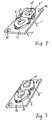
- the charging coils 6 and 6′are of annular or ring-shaped formation and are coupled to a coil yoke 12 consisting of an iron plate, a steel plate, or a plate of magnetic permeable material. Each turn of each charging coil has a substantially triangular shape, though it may have another configuration, such as circular. The resultant coils are thus of generally ring-shape.
- the pair of charging coils 6 and 6′may be connected in series or in parallel and in the Figure 2 embodiment, adjacent ends of the coils are connected. The other ends 11 and 11′ pass through holes 13 and 13′ in the coil yoke 12. Upon passing electric current through the coils 6 and 6′ from end 11 to end 11′, a magnetic field is generated by each of the coils.
- connection between the coils 6 and 6′is such that the polarity of the outer face of one coil 6 (that is the face not in contact with the yoke 12) is the opposite of the polarity of the outer face of the other coil 6′. If the current is AC, then the magnetic fields generated alternate, as do the magnetic polarities of the outer and the inner faces. The magnetic fields are opposite to each other, so that when the outer face of the charging coil 6 is of N polarity, the outer face of the charging coil 6′ is of S polarity.
- Such a systemis easily obtained by connecting the winding start ends of the charging coils 6 and 6′ to each other or by connecting the winding finish ends to each other, or by arranging the winding directions of the charging coils 6 and 6′ to be opposite to each other, or by reversing the dispostions of the respective coils on the yoke 12.
- the coil yoke 12can be secured in position by fixing screws 25 and 25′ ( Figure 9) extending through holes 14 and 14′ ( Figure 2).
- the coils 6 and 6′are wound around magnetic cores 15 and 15′ made of, for example, malleable iron and are fixed to a substrate 16 made of plastics material, glass epoxy or the like.
- the cores 15 and 15′are preferably magnetically connected by magnetic material on the inner faces thereof.
- the voltage Vtimis input to a NAND gate 101, whose output signal OPR is high when the voltage Vtim is less than the logic level V1.
- the signal OPRis high from the closure of the switch 7 until a predetermined time after the re-opening of the switch 7 set by the time constant of the timer 8.
- the signal OPRis applied to a transistor circuit 109 which drives an LED 9 whose lighting up indicates that the signal OPR is high and that the device is charging.
- the signal OPRis also applied as one input to two NAND gates 102 and 103.
- the other input of the NAND gate 102is an output signal S0 generated by the oscillator 1.
- the other input of the NAND gates 103is the output signal S1 of the NAND gate 102.
- the oscillator 1is a CR oscillator comprising a Schmitt-Trigger type NAND gate 104, a capacitor 106 and a resistor 105, which oscillator uses the input hysteresis of the NAND gate.
- the output signals S1 and S2 of the NAND gates 102 and 103, respectively,are high.
- the switching circuits 4 and 5are in the ON state, and the switching circuits 2 and 3 are in the OFF state.
- the voltages S3 and S4 at the ends 11 and 11′ of the coils 6 and 6′, respectively,are low so that no charging current is applied to the coils 6 and 6′, and no charging occurs.
- the signal S1 from the NAND gate 102is the inverted signal S0
- the signal S2 from the NAND gate 103is the doubly inverted signal S0, that is, the signal S0 without inversion.
- the frequency of the oscillator 1is such that the signals S0 have a period f .
- the switching circuit 4goes to the OFF state and the switching circuit 2 goes to the ON state.
- the voltage S3rises to a high level.
- the signal S2is at a high level and the voltage S4 is low.
- circuitscan be used to provide the alternating current to be applied to the coils 6 and 6′.
- a quartz oscillator or a ceramic oscillating circuitmay be used instead of the oscillator shown.
- the oscillator 1is driven by the power source 10, but it can be arranged that the oscillator is only operated during charging by controlling the power supplied to the oscillator from the timer 8.
- the re-chargeable analog electronic wrist watch 17has a re-chargeable, secondary battery 21 as its power source, which is in a series circuit with a rectifier or rectifying circuit 20 and a secondary coil 18.
- This coil 18has a magnetic core 19.
- the watch 17is disposed with the core 19 across the magnetic fields of the charging coils 6 and 6′ on the coil yoke 12.
- Magnetic flux 22 generated in the charging coils when the charging device is switched onpasses along the magnetic circuit composed of the coil yoke 12, the coils 6 and 6′ and the magnetic core 19 of the secondary coil 18. That is from the outer face of the coil 6, through the magnetic core 19, through the outer face of the coil 6′ to the inner face thereof, through the coil yoke 12, and the inner face of the coil 6, back to the outer face thereof. With such magnetic flux, voltage is induced across the secondary coil 18 and current flows through the series circuit including the rectifying circuit 20 to the secondary battery 21 to charge it. Because the charging coils 6 and 6′ are fixed on the coil yoke 12, most of the magnetic flux generated from the charging coils passes within the coil yoke 12, thereby making it possible to provide the effective magnetic path mentioned above.
- the value of the frequencyis the maximum one below which the movement of the hands may be affected by any mis-operation or vibration or the like, and is thus also the minimum one above which such movement is not so affected.
- the moment of inertia of the rotoris I5 and the rotor diameter is 3.0 mm, the rotor cannot be operated by pulses at a frequency greater than 200 Hz. Therefore, if the frequency for energising the coils is predetermined so as to be more than 200 Hz, the movement of the hands is not affected.
- the charging frequencyis predetermined so as to be more than 600 Hz, so that the movment of the hands is not affected.
- the rotor diameteris approximately 3.0 mm at most in view of the limitation of space and the rotor diameter is at least approximately 1.0 mm to provide sufficient power to the hands in the light of the capacity of the rotor magnet.
- Most small sized thin analog electronic wrist watcheshave a rotor diameter of about 1.5 mm. In this case, when the frequency is greater than 500 Hz, there is no problem in practice.
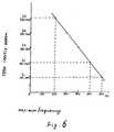
- FIG. 7is a graph of frequency for energising the charging coil and induced current flowing to the secondary battery 21 from the secondary coil 18.
- each of the charging coils 6 and 6′has a wire diameter of 0.3 mm, 170 wound turns and an inductance of 0.64 mH.
- the secondary coil 18has a wire diameter of 0.035 mm, 3830 wound turns, and an inductance of 0.5 H.
- the induced currentis highest when the frequency is near 1000 Hz. Because such a frequency is more than that required to have no effect upon the movement of hands, as shown in Figure 6, the energising frequency of the charging coils, that is, the frequency of the output signal to the oscillator 1, is predetermined so as to be approximately 1000 Hz.
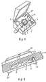
- a charging device for an analog electronic wrist watchhas a case 23 with a flat inclined surface under a hinged lid.
- the inclined surfaceis the manual switch 7 and the LED display 9 which indicates that charging is in progress.
- An analog electronic wrist watch 17 including a secondary coil 18 ( Figure 5) thereincan be mounted in a predetermined position on the inclined surface by hooks 24 and 24′ which engage watch straps on either side of the watch 17.
- the charging coils 6 and 6′are disposed inside the case 23 with the coil yoke 12 ( Figure 9) secured to the case 23 by screws 25 and 25′ extending through holes 14 and 14′ ( Figure 2) in the coil yoke 12.
- Other fixing means, such as adhesivemay be used instead of screws.
- the hooks 24 and 24′ ( Figure 8)determine the position in which the analog electronic wrist watch 17 is mounted on the charging device, so that relative positions of the charging coils 6 and 6′ and the secondary coil 18 disposed inside the electronic wrist watch 17 are determined.
- the core 19 ( Figure 5) within the secondary coil 18crosses from one coil 6 to the other coil 6′ with the axis of the coil 18 parallel to the axis of the charging coils, and good charging efficiency is obtained.
- the charging deviceis superior in efficiency and does not affect the function of the electronic apparatus, for example, does not cause any damage against movement of hands of the analog electronic wrist watch.
- Electro-magnetic inductionis used to transmit the energy needed in the charging process, so that no mechanical or electrical connection into the electronic apparatus is required. Thus, the ornamental appearance of the electronic apparatus is not affected.
- the charging device according to the present invention for electronic apparatusis described for use with an analog electronic wrist watch, but the present invention is applicable to a charging device for card-type pocket radios, liquid crystal pocket TVs and the like.
Landscapes
- Engineering & Computer Science (AREA)
- Power Engineering (AREA)
- Computer Networks & Wireless Communication (AREA)
- Physics & Mathematics (AREA)
- General Physics & Mathematics (AREA)
- Electromechanical Clocks (AREA)
- Charge And Discharge Circuits For Batteries Or The Like (AREA)
Description
- The present invention relates to charging devices for electronic apparatus.
- A typical charging device for electronic apparatus, such as an analog electronic time-piece, employs a solar battery as a part of a dial plate, arranged so that electric power produced by illumination of the solar battery charges a secondary battery. It is known from Japanese Patent Laid-Open Application No. 154665/77, Japanese Patent Laid-Open Application No. 11846/74, and Japanese Utility Model Publication No. 4240/81, that another charging device employs a charging terminal at the external portion of the time-piece, arranged so that the electric power charges a secondary battery depending on the contact with an external power source. Further, it is known from Japanese Patent Laid-Open Application No. 29783/86 that a charging device may employ an electro-magnetic connecting charge coil disposed inside a time-piece, arranged so that a magnetic field is supplied to the electro-magnetic connecting charge coil from the exterior to charge the secondary battery. In the charging device employing the electro-magnetic connecting charge coil, a counting coincidence circuit is provided in the time-piece to count the charging time. During charging, a motor is regulated and the motor driving circuit is turned to the "OFF" state. To overcome this, compensating means is provided for compensating the delay of the charging time.
- However, such previous proposals have the following disadvantages.
- First, when a solar battery system or charging terminal system is used, the design of the external appearance of the wrist watch is limited, because the wrist watch has a small size. Therefore, it is difficult to apply the solar battery or the charging terminal to analog electronic wrist watches of which the ornamental appearance is commercially important.
- Next, as to the electro-magnetic connecting system described in Japanese Patent Laid-Open Application No. 29783/86, the magnetic field supplied to the wrist watch affects a stepping motor for driving the hands, resulting in mis-operation of the hands. Therefore, during charging, motor control means, counting means and compensating means are required, so that the design of the wrist watch is limited and the cost becomes large. Further, when the charging device is used as a window display for such a wrist watch, it is necessary to stop the movement of the hands during charging, thereby making the image of the products worse. Another disadvantage is that charging may affect other analog time-pieces displayed near the window display.
- To eliminate the above problems, the present invention seeks to provide a small sized, low cost charging device for electronic apparatus, such as analog wrist watches, to provide a charging device which does not affect the function of the electronic apparatus, such as a wrist watch, and to provide a charging device which enables the charging operation to be effected in a short time with a low consumption of energy, for example in a display in a shop window.
- In Japanese Patent Laid-Open Application No. 48570/79, there is disclosed a watch driven by a battery connected through a rectifying circuit to a coil wound on a core. By placing the watch within magnetic fields, induced voltage is generated in the coil, so that the battery in the watch is charged without removal from the watch.
- In Japanese Patent Laid-Open Application No. 82473/79, there is disclosed a charging device for re-charging a re-chargeable battery in an electronic watch. The charging device is an a.c. magnetism generator including a coil to which alternating current is applied. The watch includes a coil electrically connected to the re-chargeable battery through a rectifier circuit. During charging, the watch is disposed close to the charging device, so that alternating current is electro-magnetically induced in the coil and used to recharge the battery.
- The invention seeks to improve the efficiency of the electromagnetic transmission of energy in such an arrangement.
- Accordingly, a charging device for re-charging a re-chargeable power source in electronic apparatus, including charging coil means and means to apply current to the charging coil means at a predetermined frequency, the electronic apparatus including secondary coil means electrically connected to the rechargeable power source, and the charging coil means being so disposed that the secondary coil means in an electronic apparatus associated with the charging device has a current of the predetermined frequency electro-magnetically induced therein to re-charge the re-chargeable source, is characterised in that the charging coil means comprises a pair of charging coils of annular or ring-shaped formation, disposed adjacent to each other, the polarity of one of the charging coils being opposite to the other of the charging coils, so as to produce opposite magnetic fields at the outer faces of the charging coils.
- Preferably, a coil yoke of magnetic permeable material is disposed across the charging coils on the side remote from that close to which the secondary coil means in an electronic apparatus is intended to be placed.
- The secondary coil means may have a core of magnetic permeable material across the charging coils of an electronic apparatus associated with the charging device.
- The means for applying current to the charging coils may include an oscillator circuit and switching circuits controlled by the output from the oscillator circuit.
- The charging coils are preferably of substantially triangular shape.
- Conveniently, the charging coils are connected in series.
- In the case when the electronic apparatus includes a component or components liable to be affected by induced current, the predetermined frequency is with advantage outside the range of frequencies within which such component or components is or are affected.
- The component in the electronic apparatus, which is liable to be affected, may be a motor having a permanent magnetic rotor.
- The frequency is preferably greater than 200 Hz, 500 Hz or even 600 Hz. To achieve a high charging efficiency, the frequency may be approximately 1 kHz.
- The device may include a case capable of receiving an electronic apparatus adjacent the charging coils.
- For a fuller understanding of the invention, reference may be had to the following description, with reference to the accompanying drawings, in which:-
- Figure 1 is a circuit diagram of one embodiment of a charging device according to the present invention for electronic apparatus;
- Figure 2 is a perspective diagrammatic-view of the structure of the charging coils in the device of Figure 1;
- Figure 3 is a similar view of another structure of the charging coils in that device;
- Figure 4 is a timing chart showing the energising timing of the charging coils and other parts of the circuit of Figure 1;
- Figure 5 is a diagrammatic view to assist explanation of the theory of the charging device of the present invention;
- Figure 6 is a graph showing the relation between a rotor moment of inertia and the limit of magnetic field frequency;
- Figure 7 is a graph showing the relation between the energising frequency of the charging coils and the induced current;
- Figure 8 is a perspective view of a charging device with an analog electronic wrist watch in position for charging; and
- Figure 9 is a scrap view, partly in section, showing the assembled structure of the charging coil and the case.
- A charging device (Figure 1) for an electronic apparatus according to the present invention, includes an
oscillator 1, fourswitching circuits charging coils manual switch 7, atimer 8 which starts charging operation when theswitch 7 is closed and stops the charging operation a predetermined time after theswitch 7 is re-opened a display 9 such as a light emitting diode, to indicate that charging is being carried out, and apower source 10. - The
charging coils coil yoke 12 consisting of an iron plate, a steel plate, or a plate of magnetic permeable material. Each turn of each charging coil has a substantially triangular shape, though it may have another configuration, such as circular. The resultant coils are thus of generally ring-shape. The pair ofcharging coils coil yoke 12. Upon passing electric current through thecoils coils other coil 6′. If the current is AC, then the magnetic fields generated alternate, as do the magnetic polarities of the outer and the inner faces. The magnetic fields are opposite to each other, so that when the outer face of thecharging coil 6 is of N polarity, the outer face of thecharging coil 6′ is of S polarity. Such a system is easily obtained by connecting the winding start ends of thecharging coils charging coils yoke 12. Thecoil yoke 12 can be secured in position byfixing screws holes - In a modification of such a charging device according to the present invention, the
coils magnetic cores substrate 16 made of plastics material, glass epoxy or the like. Thecores - Reference is made to the timing chart of Figure 4, which shows the timing for operation of the circuit and for energisation of the coils. When the
manual switch 7 is closed, the voltage Vtim across the switch is reduced to a low level and a capacitor 108 (Figure 1) of thetimer 8 is charged by thepower source 10. When theswitch 7 is re-opened, the charge in the capacitor 108 is discharged gradually through a resistor 107 of thetimer 8, the rate of discharge being determined by the time constant of the resistance of the resistor and the capacitance of the capacitor. During discharge of the capacitor 108, the voltage Vtim increases gradually (Figure 4), passes a logic level V1 and approaches a high level. The voltage Vtim is input to aNAND gate 101, whose output signal OPR is high when the voltage Vtim is less than the logic level V1. Thus the signal OPR is high from the closure of theswitch 7 until a predetermined time after the re-opening of theswitch 7 set by the time constant of thetimer 8. The signal OPR is applied to atransistor circuit 109 which drives an LED 9 whose lighting up indicates that the signal OPR is high and that the device is charging. - The signal OPR is also applied as one input to two
NAND gates NAND gate 102 is an output signal S0 generated by theoscillator 1. The other input of theNAND gates 103 is the output signal S1 of theNAND gate 102. Theoscillator 1 is a CR oscillator comprising a Schmitt-Triggertype NAND gate 104, acapacitor 106 and aresistor 105, which oscillator uses the input hysteresis of the NAND gate. When the signal OPR is low, the output signals S1 and S2 of theNAND gates circuits 4 and 5 are in the ON state, and the switchingcircuits 2 and 3 are in the OFF state. The voltages S3 and S4 at the ends 11 and 11′ of thecoils coils - When the signal OPR is high, the signal S1 from the
NAND gate 102 is the inverted signal S0, whilst the signal S2 from theNAND gate 103 is the doubly inverted signal S0, that is, the signal S0 without inversion. The frequency of theoscillator 1 is such that the signals S0 have a periodf. As the signal S1 falls to a low level (Figure 4), the switchingcircuit 4 goes to the OFF state and theswitching circuit 2 goes to the ON state. The voltage S3 rises to a high level. At this time, the signal S2 is at a high level and the voltage S4 is low. Accordingly, current flows through thecoils circuit 2 goes to an OFF state and theswitching circuit 4 goes to the ON state. Reducing the voltage S3 to a low level. At the same time, the signal S2 falls to a low level, turning the switching circuit 5 to the OFF state and the switching circuit 3 to the ON state. The voltage S4 rises to a high level and current again flows through thecoils coils - Other circuits can be used to provide the alternating current to be applied to the
coils oscillator 1 is driven by thepower source 10, but it can be arranged that the oscillator is only operated during charging by controlling the power supplied to the oscillator from thetimer 8. - To explain the theory behind the charging device of the present invention, when the charging coils are energised as described above, part of the charging device as shown in Figure 5 is applied to the charging of an analog electronic wrist watch. The re-chargeable analog
electronic wrist watch 17 has a re-chargeable,secondary battery 21 as its power source, which is in a series circuit with a rectifier or rectifyingcircuit 20 and a secondary coil 18. This coil 18 has a magnetic core 19. Thewatch 17 is disposed with the core 19 across the magnetic fields of the charging coils 6 and 6′ on thecoil yoke 12. Magnetic flux 22 generated in the charging coils when the charging device is switched on, passes along the magnetic circuit composed of thecoil yoke 12, thecoils coil 6, through the magnetic core 19, through the outer face of thecoil 6′ to the inner face thereof, through thecoil yoke 12, and the inner face of thecoil 6, back to the outer face thereof. With such magnetic flux, voltage is induced across the secondary coil 18 and current flows through the series circuit including the rectifyingcircuit 20 to thesecondary battery 21 to charge it. Because the charging coils 6 and 6′ are fixed on thecoil yoke 12, most of the magnetic flux generated from the charging coils passes within thecoil yoke 12, thereby making it possible to provide the effective magnetic path mentioned above. Without such a coil yoke, much magnetic flux leaks into the air, and as a result, charging efficiency is lowered. Further, because the respective polarities of thecoils coil 6 passes along the magnetic core 19 and passes across theother charging coil 6′ securely, so that the charging efficiency is increased. If the polarity of one charging coil is the same as that of the other coil, the magnetic fluxes repel each other and as a result, the amount of the magnetic flux in the core 19 is decreased and the charging efficiency is decreased. Therefore, a charging device according to the present invention, enables the charging efficiency to be increased.- The selection of a frequency for energising the coils to re-charge the battery in an analog electronic wrist watch driven by a stepping motor, must take into consideration the effect upon the rotor of the stepping motor of such frequency and it has been found that this is related to the moment of inertia of the rotor. This relationship is illustrated in Figure 6, which is a graph showing the relation between the limit frequency of AC magnetic field and the moment of inertia of the rotor (the rotor diameter being indicated as a parameter), when the rotor of the stepping motor for driving the movement of the electronic wrist watch is not affected. The value of the frequency is the maximum one below which the movement of the hands may be affected by any mis-operation or vibration or the like, and is thus also the minimum one above which such movement is not so affected. When the moment of inertia of the rotor is I5 and the rotor diameter is 3.0 mm, the rotor cannot be operated by pulses at a frequency greater than 200 Hz. Therefore, if the frequency for energising the coils is predetermined so as to be more than 200 Hz, the movement of the hands is not affected. Similarly, when the moment of inertia of the rotor is I1 and the rotor diameter is 1.0 mm, the charging frequency is predetermined so as to be more than 600 Hz, so that the movment of the hands is not affected. In general, in an analog electronic wrist watch, the rotor diameter is approximately 3.0 mm at most in view of the limitation of space and the rotor diameter is at least approximately 1.0 mm to provide sufficient power to the hands in the light of the capacity of the rotor magnet. Most small sized thin analog electronic wrist watches have a rotor diameter of about 1.5 mm. In this case, when the frequency is greater than 500 Hz, there is no problem in practice.
- The selection of a frequency for energising the charging coils also must take into consideration the current to be induced in the secondary coil in the electronic apparatus. This, in turn, is affected by the size and number of turns of the coils and their inductances. As an example, illustrating the relationship, Figure 7 is a graph of frequency for energising the charging coil and induced current flowing to the
secondary battery 21 from the secondary coil 18. In the example, each of the charging coils 6 and 6′ has a wire diameter of 0.3 mm, 170 wound turns and an inductance of 0.64 mH. The secondary coil 18 has a wire diameter of 0.035 mm, 3830 wound turns, and an inductance of 0.5 H. As shown in Figure 7, the induced current is highest when the frequency is near 1000 Hz. Because such a frequency is more than that required to have no effect upon the movement of hands, as shown in Figure 6, the energising frequency of the charging coils, that is, the frequency of the output signal to theoscillator 1, is predetermined so as to be approximately 1000 Hz. - In a practical embodiment of the present invention (Figure 8) a charging device for an analog electronic wrist watch has a
case 23 with a flat inclined surface under a hinged lid. In the inclined surface is themanual switch 7 and the LED display 9 which indicates that charging is in progress. - An analog electronic wrist watch 17 including a secondary coil 18 (Figure 5) therein can be mounted in a predetermined position on the inclined surface by hooks 24 and 24′ which engage watch straps on either side of the
watch 17. The charging coils 6 and 6′ are disposed inside thecase 23 with the coil yoke 12 (Figure 9) secured to thecase 23 byscrews holes coil yoke 12. Other fixing means, such as adhesive may be used instead of screws. The hooks 24 and 24′ (Figure 8) determine the position in which the analogelectronic wrist watch 17 is mounted on the charging device, so that relative positions of the charging coils 6 and 6′ and the secondary coil 18 disposed inside theelectronic wrist watch 17 are determined. Thus the core 19 (Figure 5) within the secondary coil 18 crosses from onecoil 6 to theother coil 6′ with the axis of the coil 18 parallel to the axis of the charging coils, and good charging efficiency is obtained. - As described hereinbefore, in accordance with the present invention, the charging device is superior in efficiency and does not affect the function of the electronic apparatus, for example, does not cause any damage against movement of hands of the analog electronic wrist watch. Electro-magnetic induction is used to transmit the energy needed in the charging process, so that no mechanical or electrical connection into the electronic apparatus is required. Thus, the ornamental appearance of the electronic apparatus is not affected.
- The charging device according to the present invention for electronic apparatus is described for use with an analog electronic wrist watch, but the present invention is applicable to a charging device for card-type pocket radios, liquid crystal pocket TVs and the like.
Claims (13)
- A charging device for recharging a re-chargeable power source (21) in electronic apparatus (17), including charging coil means (6,6′) and means (1,2,3,4,5) to apply current to the charging coil means at a predetermined frequency, the electronic apparatus including secondary coil means (18) electrically connected to the re-chargeable power source, and the charging coil means being so disposed that the secondary coil means in an electronic apparatus associated with the charging device has a current of the predetermined frequency electro-magnetically induced therein to re-charge the re-chargeable source, characterised in that the charging coil means comprises a pair of charging coils (6,6′) of annular or ring-shaped formation, disposed adjacent to each other, the polarity of one of the charging coils being opposite to the other of the charging coils, so as to produce opposite magnetic fields at the outer faces of the charging coils.
- A device as claimed in claim 1, characterised in that a coil yoke (12) of magnetic permeable material is disposed across the charging coils (6, 6′) on the side remote from that close to which the secondary coil means (18) in an electronic apparatus (17) is intended to be placed.
- A device as claimed in claim 1 or 2, wherein the secondary coil means (18) has a core (19) of magnetic permeable material across the charging coils (6,6′) of an electronic apparatus associated with the charging device.
- A device as claimed in claim 1,2 or 3, wherein the means for applying current to the charging coils (6, 6′) includes an oscillator circuit (1) and switching circuits (2,3,4,5) controlled by the output from the oscillator circuit (1).
- A device as claimed in any preceding claim, wherein the charging coils (6,6′) are of substantially triangular shape.
- A device as claimed in any preceding claim, wherein the charging coils (6,6′) are connected in series.
- A device as claimed in any preceding claim, wherein the electronic apparatus (17) includes a component or components liable to be affected by induced electrical current, characterised in that the predetermined frequency is outside the range of frequencies within which such component or components is or are affected.
- A device as claimed in claim 7, wherein the component in the electronic apparatus (17), which is liable to be affected, is a motor having a permanent magnet rotor.
- A device as claimed in claim 7 or 8, wherein the frequency is greater than 200 Hz.
- A device as claimed in claim 9, wherein the frequency is greater than 500 Hz.
- A device as claimed in claim 10, wherein the frequency is greater than 600 Hz.
- A device as claimed in claim 11, wherein the frequency is predetermined to have a high charging efficiency, and is approximately 1kHz.
- A device as claimed in any preceding claim, including a case (23) capable of receiving an electronic apparatus (17) adjacent the charging coils (6,6′).
Applications Claiming Priority (8)
| Application Number | Priority Date | Filing Date | Title |
|---|---|---|---|
| JP1987106457UJPH0629753Y2 (en) | 1987-07-10 | 1987-07-10 | Watch charging system |
| JP106457/87U | 1987-07-10 | ||
| JP176399/87 | 1987-07-15 | ||
| JP176400/87 | 1987-07-15 | ||
| JP176401/87 | 1987-07-15 | ||
| JP62176401AJP2576869B2 (en) | 1987-07-15 | 1987-07-15 | Small charging device |
| JP62176400AJPS6423729A (en) | 1987-07-15 | 1987-07-15 | Recharger for electronic clock |
| JP62176399AJP2822033B2 (en) | 1987-07-15 | 1987-07-15 | Small charging device |
Publications (3)
| Publication Number | Publication Date |
|---|---|
| EP0298707A2 EP0298707A2 (en) | 1989-01-11 |
| EP0298707A3 EP0298707A3 (en) | 1990-06-20 |
| EP0298707B1true EP0298707B1 (en) | 1994-09-28 |
Family
ID=27469427
Family Applications (1)
| Application Number | Title | Priority Date | Filing Date |
|---|---|---|---|
| EP88306128AExpired - LifetimeEP0298707B1 (en) | 1987-07-10 | 1988-07-06 | Charging device for electronic apparatus |
Country Status (6)
| Country | Link |
|---|---|
| US (1) | US4873677A (en) |
| EP (1) | EP0298707B1 (en) |
| KR (1) | KR940008707B1 (en) |
| CN (1) | CN1014555B (en) |
| DE (1) | DE3851664T2 (en) |
| HK (1) | HK102597A (en) |
Cited By (15)
| Publication number | Priority date | Publication date | Assignee | Title |
|---|---|---|---|---|
| EP0456436A3 (en)* | 1990-05-08 | 1992-03-18 | Biohit Oy | Pipette charging system |
| CH681267A5 (en)* | 1991-02-19 | 1993-02-26 | Battery charging device for electronic wrist watch | |
| US5550452A (en)* | 1993-07-26 | 1996-08-27 | Nintendo Co., Ltd. | Induction charging apparatus |
| GB2330461A (en)* | 1994-06-30 | 1999-04-21 | Nec Corp | Inductively coupled battery charger |
| GB2291291B (en)* | 1994-06-30 | 1999-06-02 | Nec Corp | Noncontacting charging device |
| US6028413A (en)* | 1997-09-19 | 2000-02-22 | Perdix Oy | Charging device for batteries in a mobile electrical device |
| US6316909B1 (en) | 1998-03-24 | 2001-11-13 | Seiko Epson Corporation | Electronic device, control method for electronic device, recharge-rate estimating method for secondary battery, and charging control method for secondary battery |
| US6525996B1 (en) | 1998-12-22 | 2003-02-25 | Seiko Epson Corporation | Power feeding apparatus, power receiving apparatus, power transfer system, power transfer method, portable apparatus, and timepiece |
| WO2003105308A1 (en)* | 2002-01-11 | 2003-12-18 | City University Of Hong Kong | Planar inductive battery charger |
| US6721540B1 (en) | 1999-03-19 | 2004-04-13 | Seiko Epson Corporation | Electronic device |
| CN101978571A (en)* | 2007-12-21 | 2011-02-16 | 捷通国际有限公司 | Circuits for inductive power transfer |
| US8447234B2 (en) | 2006-01-18 | 2013-05-21 | Qualcomm Incorporated | Method and system for powering an electronic device via a wireless link |
| US9124120B2 (en) | 2007-06-11 | 2015-09-01 | Qualcomm Incorporated | Wireless power system and proximity effects |
| US9130602B2 (en) | 2006-01-18 | 2015-09-08 | Qualcomm Incorporated | Method and apparatus for delivering energy to an electrical or electronic device via a wireless link |
| US9601267B2 (en) | 2013-07-03 | 2017-03-21 | Qualcomm Incorporated | Wireless power transmitter with a plurality of magnetic oscillators |
Families Citing this family (108)
| Publication number | Priority date | Publication date | Assignee | Title |
|---|---|---|---|---|
| AU6407590A (en)* | 1989-10-18 | 1991-05-31 | At & E Corporation. | Wristwatch pager with battery charger |
| ES2104502B1 (en)* | 1994-11-04 | 1998-05-16 | Planells Almerich Francisco | CHARGING SYSTEM OF THE CLOCK STACK WITHOUT OPENING THE LID. |
| US5764594A (en)* | 1996-05-23 | 1998-06-09 | Berman; Paul | Silent alarm clock |
| US5734254A (en)* | 1996-12-06 | 1998-03-31 | Hewlett-Packard Company | Battery pack and charging system for a portable electronic device |
| AU3046297A (en) | 1997-06-16 | 1999-01-04 | Yehuda Binder | Battery substitute pack |
| JPH1140207A (en)* | 1997-07-22 | 1999-02-12 | Sanyo Electric Co Ltd | Pack battery and charging table |
| DE19741279A1 (en)* | 1997-09-19 | 1999-03-25 | Salcomp Oy | Induction battery charging device for portable equipment |
| JP3887828B2 (en)* | 1997-11-20 | 2007-02-28 | セイコーエプソン株式会社 | Electronics |
| CH713523B1 (en) | 2001-11-26 | 2018-09-14 | Ebauchesfabrik Eta Ag | Portable electronic object such as a timepiece that can be worn on the wrist. |
| EP1315051A1 (en)* | 2001-11-26 | 2003-05-28 | ETA SA Manufacture Horlogère Suisse | Small electronic object that can be wrist worn |
| GB2388716B (en)* | 2002-05-13 | 2004-10-20 | Splashpower Ltd | Improvements relating to contact-less power transfer |
| US6906495B2 (en)* | 2002-05-13 | 2005-06-14 | Splashpower Limited | Contact-less power transfer |
| GB2398176B (en)* | 2002-05-13 | 2006-03-08 | Zap Wireless Technologies Ltd | Improvements relating to contact-less power transfer |
| US8917057B2 (en) | 2002-06-10 | 2014-12-23 | City University Of Hong Kong | Battery charging system |
| DE10393604T5 (en) | 2002-10-28 | 2005-11-03 | Splashpower Ltd. | Improvements in non-contact power transmission |
| EP1721237B1 (en)* | 2004-02-27 | 2012-08-29 | Simon Richard Daniel | Wearable modular interface strap |
| US7211986B1 (en)* | 2004-07-01 | 2007-05-01 | Plantronics, Inc. | Inductive charging system |
| US7775966B2 (en) | 2005-02-24 | 2010-08-17 | Ethicon Endo-Surgery, Inc. | Non-invasive pressure measurement in a fluid adjustable restrictive device |
| US8066629B2 (en) | 2005-02-24 | 2011-11-29 | Ethicon Endo-Surgery, Inc. | Apparatus for adjustment and sensing of gastric band pressure |
| US7927270B2 (en) | 2005-02-24 | 2011-04-19 | Ethicon Endo-Surgery, Inc. | External mechanical pressure sensor for gastric band pressure measurements |
| US8016744B2 (en) | 2005-02-24 | 2011-09-13 | Ethicon Endo-Surgery, Inc. | External pressure-based gastric band adjustment system and method |
| US7658196B2 (en) | 2005-02-24 | 2010-02-09 | Ethicon Endo-Surgery, Inc. | System and method for determining implanted device orientation |
| US7775215B2 (en) | 2005-02-24 | 2010-08-17 | Ethicon Endo-Surgery, Inc. | System and method for determining implanted device positioning and obtaining pressure data |
| US7699770B2 (en) | 2005-02-24 | 2010-04-20 | Ethicon Endo-Surgery, Inc. | Device for non-invasive measurement of fluid pressure in an adjustable restriction device |
| US11201500B2 (en) | 2006-01-31 | 2021-12-14 | Mojo Mobility, Inc. | Efficiencies and flexibilities in inductive (wireless) charging |
| US7952322B2 (en)* | 2006-01-31 | 2011-05-31 | Mojo Mobility, Inc. | Inductive power source and charging system |
| US8169185B2 (en) | 2006-01-31 | 2012-05-01 | Mojo Mobility, Inc. | System and method for inductive charging of portable devices |
| US8870742B2 (en) | 2006-04-06 | 2014-10-28 | Ethicon Endo-Surgery, Inc. | GUI for an implantable restriction device and a data logger |
| US8152710B2 (en) | 2006-04-06 | 2012-04-10 | Ethicon Endo-Surgery, Inc. | Physiological parameter analysis for an implantable restriction device and a data logger |
| US7948208B2 (en) | 2006-06-01 | 2011-05-24 | Mojo Mobility, Inc. | Power source, charging system, and inductive receiver for mobile devices |
| US11329511B2 (en) | 2006-06-01 | 2022-05-10 | Mojo Mobility Inc. | Power source, charging system, and inductive receiver for mobile devices |
| US20070290654A1 (en)* | 2006-06-14 | 2007-12-20 | Assaf Govari | Inductive charging of tools on surgical tray |
| JP2008135589A (en)* | 2006-11-29 | 2008-06-12 | Asuka Electron Kk | Coil for power transmission |
| US9774086B2 (en) | 2007-03-02 | 2017-09-26 | Qualcomm Incorporated | Wireless power apparatus and methods |
| US9466419B2 (en) | 2007-05-10 | 2016-10-11 | Auckland Uniservices Limited | Apparatus and system for charging a battery |
| KR102128564B1 (en) | 2007-05-10 | 2020-07-01 | 오클랜드 유니서비시즈 리미티드 | Multi power sourced electric vehicle |
| GB0716679D0 (en)* | 2007-08-28 | 2007-10-03 | Fells J | Inductive power supply |
| US8187163B2 (en) | 2007-12-10 | 2012-05-29 | Ethicon Endo-Surgery, Inc. | Methods for implanting a gastric restriction device |
| US8100870B2 (en) | 2007-12-14 | 2012-01-24 | Ethicon Endo-Surgery, Inc. | Adjustable height gastric restriction devices and methods |
| US8142452B2 (en) | 2007-12-27 | 2012-03-27 | Ethicon Endo-Surgery, Inc. | Controlling pressure in adjustable restriction devices |
| US8377079B2 (en) | 2007-12-27 | 2013-02-19 | Ethicon Endo-Surgery, Inc. | Constant force mechanisms for regulating restriction devices |
| US8192350B2 (en) | 2008-01-28 | 2012-06-05 | Ethicon Endo-Surgery, Inc. | Methods and devices for measuring impedance in a gastric restriction system |
| US8337389B2 (en) | 2008-01-28 | 2012-12-25 | Ethicon Endo-Surgery, Inc. | Methods and devices for diagnosing performance of a gastric restriction system |
| US8591395B2 (en) | 2008-01-28 | 2013-11-26 | Ethicon Endo-Surgery, Inc. | Gastric restriction device data handling devices and methods |
| US7844342B2 (en) | 2008-02-07 | 2010-11-30 | Ethicon Endo-Surgery, Inc. | Powering implantable restriction systems using light |
| US8221439B2 (en) | 2008-02-07 | 2012-07-17 | Ethicon Endo-Surgery, Inc. | Powering implantable restriction systems using kinetic motion |
| US8114345B2 (en) | 2008-02-08 | 2012-02-14 | Ethicon Endo-Surgery, Inc. | System and method of sterilizing an implantable medical device |
| US8057492B2 (en) | 2008-02-12 | 2011-11-15 | Ethicon Endo-Surgery, Inc. | Automatically adjusting band system with MEMS pump |
| US8591532B2 (en) | 2008-02-12 | 2013-11-26 | Ethicon Endo-Sugery, Inc. | Automatically adjusting band system |
| US8034065B2 (en) | 2008-02-26 | 2011-10-11 | Ethicon Endo-Surgery, Inc. | Controlling pressure in adjustable restriction devices |
| US8187162B2 (en) | 2008-03-06 | 2012-05-29 | Ethicon Endo-Surgery, Inc. | Reorientation port |
| US8233995B2 (en) | 2008-03-06 | 2012-07-31 | Ethicon Endo-Surgery, Inc. | System and method of aligning an implantable antenna |
| US20110050164A1 (en) | 2008-05-07 | 2011-03-03 | Afshin Partovi | System and methods for inductive charging, and improvements and uses thereof |
| CN104539027A (en) | 2008-07-09 | 2015-04-22 | 捷通国际有限公司 | Wireless charging system |
| US9032880B2 (en) | 2009-01-23 | 2015-05-19 | Magnemotion, Inc. | Transport system powered by short block linear synchronous motors and switching mechanism |
| US8616134B2 (en)* | 2009-01-23 | 2013-12-31 | Magnemotion, Inc. | Transport system powered by short block linear synchronous motors |
| US8967051B2 (en)* | 2009-01-23 | 2015-03-03 | Magnemotion, Inc. | Transport system powered by short block linear synchronous motors and switching mechanism |
| WO2010090539A1 (en) | 2009-02-05 | 2010-08-12 | Auckland Uniservices Limited | Inductive power transfer apparatus |
| WO2010090538A1 (en) | 2009-02-05 | 2010-08-12 | Auckland Uniservices Limited | Inductive power transfer apparatus |
| US8427100B2 (en)* | 2009-02-06 | 2013-04-23 | Broadcom Corporation | Increasing efficiency of wireless power transfer |
| US20100201310A1 (en)* | 2009-02-06 | 2010-08-12 | Broadcom Corporation | Wireless power transfer system |
| US8427330B2 (en)* | 2009-02-06 | 2013-04-23 | Broadcom Corporation | Efficiency indicator for increasing efficiency of wireless power transfer |
| US8686684B2 (en)* | 2009-03-27 | 2014-04-01 | Microsoft Corporation | Magnetic inductive charging with low far fields |
| DE102009022886A1 (en)* | 2009-05-27 | 2010-12-02 | Bayerische Motoren Werke Aktiengesellschaft | Device for the mechanical and electrical connection of a portable, battery-operated device and portable, battery-powered device |
| US8460816B2 (en)* | 2009-10-08 | 2013-06-11 | Etymotic Research, Inc. | Rechargeable battery assemblies and methods of constructing rechargeable battery assemblies |
| US8174233B2 (en)* | 2009-10-08 | 2012-05-08 | Etymotic Research, Inc. | Magnetically coupled battery charging system |
| US8237402B2 (en)* | 2009-10-08 | 2012-08-07 | Etymotic Research, Inc. | Magnetically coupled battery charging system |
| US8022775B2 (en)* | 2009-10-08 | 2011-09-20 | Etymotic Research, Inc. | Systems and methods for maintaining a drive signal to a resonant circuit at a resonant frequency |
| US8174234B2 (en)* | 2009-10-08 | 2012-05-08 | Etymotic Research, Inc. | Magnetically coupled battery charging system |
| US8355297B2 (en) | 2009-11-05 | 2013-01-15 | Devon Works, LLC | Watch assembly having a plurality of time-coordinated belts |
| WO2011156768A2 (en) | 2010-06-11 | 2011-12-15 | Mojo Mobility, Inc. | System for wireless power transfer that supports interoperability, and multi-pole magnets for use therewith |
| EP2428969B1 (en)* | 2010-08-09 | 2016-10-19 | Parspour, Nejila | Coil arrangement for an inductive charging device |
| TWM399634U (en)* | 2010-10-04 | 2011-03-11 | Gooten Innolife Corp | Watch winder with noncontact transmission function |
| US10115520B2 (en) | 2011-01-18 | 2018-10-30 | Mojo Mobility, Inc. | Systems and method for wireless power transfer |
| US9178369B2 (en) | 2011-01-18 | 2015-11-03 | Mojo Mobility, Inc. | Systems and methods for providing positioning freedom, and support of different voltages, protocols, and power levels in a wireless power system |
| US11342777B2 (en) | 2011-01-18 | 2022-05-24 | Mojo Mobility, Inc. | Powering and/or charging with more than one protocol |
| US9496732B2 (en) | 2011-01-18 | 2016-11-15 | Mojo Mobility, Inc. | Systems and methods for wireless power transfer |
| US20120244969A1 (en) | 2011-03-25 | 2012-09-27 | May Patents Ltd. | System and Method for a Motion Sensing Device |
| US9496081B2 (en) | 2011-04-08 | 2016-11-15 | Access Business Group International Llc | Counter wound inductive power supply |
| KR101668925B1 (en) | 2011-06-07 | 2016-10-24 | 마그네모션, 인코포레이티드 | Versatile control of a linear synchronous motor propulsion system |
| CN103051037A (en)* | 2011-10-11 | 2013-04-17 | 宏碁股份有限公司 | electronic device |
| US10673274B2 (en)* | 2011-10-17 | 2020-06-02 | Auckland Uniservices Limited | Inductive power transfer apparatus |
| US9118203B2 (en)* | 2011-11-15 | 2015-08-25 | Qualcomm Incorporated | Systems and methods for induction charging with a closed magnetic loop |
| US9236756B2 (en)* | 2011-12-05 | 2016-01-12 | Qualcomm Incorporated | Apparatus for wireless device charging using radio frequency (RF) energy and device to be wirelessly charged |
| US9722447B2 (en) | 2012-03-21 | 2017-08-01 | Mojo Mobility, Inc. | System and method for charging or powering devices, such as robots, electric vehicles, or other mobile devices or equipment |
| US20130271069A1 (en) | 2012-03-21 | 2013-10-17 | Mojo Mobility, Inc. | Systems and methods for wireless power transfer |
| JP6378175B2 (en) | 2012-07-09 | 2018-08-22 | オークランド ユニサービシズ リミテッドAuckland Uniservices Limited | Magnetic flux coupling device and magnetic structure thereof |
| US9870859B2 (en) | 2012-07-15 | 2018-01-16 | Access Business Group International Llc | Variable mode wireless power supply systems |
| US9362776B2 (en)* | 2012-11-27 | 2016-06-07 | Qualcomm Incorporated | Wireless charging systems and methods |
| US9837846B2 (en) | 2013-04-12 | 2017-12-05 | Mojo Mobility, Inc. | System and method for powering or charging receivers or devices having small surface areas or volumes |
| EP3038487B1 (en)* | 2013-08-26 | 2018-06-13 | Fidlock GmbH | Magnetic band device, in particular wristband |
| WO2015042409A1 (en) | 2013-09-21 | 2015-03-26 | Magnemotion, Inc. | Linear motor transport for packaging and other uses |
| JP5839020B2 (en) | 2013-11-28 | 2016-01-06 | Tdk株式会社 | Power transmission coil unit and wireless power transmission device |
| JP6179375B2 (en) | 2013-11-28 | 2017-08-16 | Tdk株式会社 | Coil unit |
| JP2015106581A (en) | 2013-11-28 | 2015-06-08 | Tdk株式会社 | Power transmission coil unit and wireless power transmission device |
| JP6164421B2 (en) | 2013-11-28 | 2017-07-19 | Tdk株式会社 | Power transmission coil unit and wireless power transmission device |
| JP6432251B2 (en) | 2013-11-28 | 2018-12-05 | Tdk株式会社 | Power transmission coil unit and wireless power transmission device |
| EP3180835A4 (en) | 2014-08-12 | 2017-09-13 | PowerbyProxi Limited | System and method for power transfer |
| KR102363641B1 (en)* | 2015-01-14 | 2022-02-17 | 삼성전자주식회사 | Wearable device |
| US9996055B2 (en)* | 2015-10-22 | 2018-06-12 | Griffin Technology, Llc | Watch stand |
| US10530176B2 (en)* | 2016-03-02 | 2020-01-07 | Andrew Bradford Green | Travel case and stand for smart watch |
| WO2017204663A1 (en) | 2016-05-25 | 2017-11-30 | Powerbyproxi Limited | A coil arrangement |
| US20180123392A1 (en)* | 2016-10-31 | 2018-05-03 | Apple Inc. | Wireless Charging System With Solenoids |
| JP7126544B2 (en) | 2017-07-07 | 2022-08-26 | ニューロダーム リミテッド | Vial adapter, method and filling system for filling a reservoir of a drug delivery device with a flowable drug using the vial adapter |
| US20230123806A1 (en) | 2017-07-07 | 2023-04-20 | Neuroderm, Ltd. | Device for subcutaneous delivery of fluid medicament |
| US11342108B2 (en) | 2018-05-11 | 2022-05-24 | International Business Machines Corporation | Stackable near-field communications antennas |
| CN110611130A (en)* | 2018-06-15 | 2019-12-24 | 元创绿能科技股份有限公司 | Rechargeable battery and method for controlling electron dissociation of metal atoms for charging |
| US11444485B2 (en) | 2019-02-05 | 2022-09-13 | Mojo Mobility, Inc. | Inductive charging system with charging electronics physically separated from charging coil |
Family Cites Families (7)
| Publication number | Priority date | Publication date | Assignee | Title |
|---|---|---|---|---|
| DE1027143B (en)* | 1957-02-05 | 1958-03-27 | Kieninger & Obergfell | Electric clock |
| CH336027A (en)* | 1957-07-19 | 1959-01-31 | Omega Brandt & Freres Sa Louis | Device intended to recharge at least one electric accumulator placed in a wristwatch |
| US4371269A (en)* | 1980-09-09 | 1983-02-01 | Bulova Watch Co., Inc. | D-C Voltage converter for a wristwatch |
| GB8328750D0 (en)* | 1983-10-27 | 1983-11-30 | Philp R | Contact-less electronic connectors |
| JPH0756517B2 (en)* | 1984-02-22 | 1995-06-14 | セイコーエプソン株式会社 | Small generator |
| NL8402113A (en)* | 1984-07-03 | 1986-02-03 | Kinetron Bv | SYSTEM FOR ELECTRICAL SUPPLY OF PORTABLE MINIATURE ENERGY CONSUMERS. |
| GB8625429D0 (en)* | 1986-10-23 | 1986-11-26 | Philp R | Contactless electronic connectors |
- 1988
- 1988-07-06DEDE3851664Tpatent/DE3851664T2/ennot_activeExpired - Fee Related
- 1988-07-06EPEP88306128Apatent/EP0298707B1/ennot_activeExpired - Lifetime
- 1988-07-07USUS07/216,914patent/US4873677A/ennot_activeExpired - Lifetime
- 1988-07-08KRKR1019880008472Apatent/KR940008707B1/ennot_activeExpired - Fee Related
- 1988-07-09CNCN88104380Apatent/CN1014555B/ennot_activeExpired
- 1997
- 1997-06-26HKHK102597Apatent/HK102597A/ennot_activeIP Right Cessation
Cited By (17)
| Publication number | Priority date | Publication date | Assignee | Title |
|---|---|---|---|---|
| EP0456436A3 (en)* | 1990-05-08 | 1992-03-18 | Biohit Oy | Pipette charging system |
| CH681267A5 (en)* | 1991-02-19 | 1993-02-26 | Battery charging device for electronic wrist watch | |
| US5550452A (en)* | 1993-07-26 | 1996-08-27 | Nintendo Co., Ltd. | Induction charging apparatus |
| GB2330461A (en)* | 1994-06-30 | 1999-04-21 | Nec Corp | Inductively coupled battery charger |
| GB2291291B (en)* | 1994-06-30 | 1999-06-02 | Nec Corp | Noncontacting charging device |
| GB2330461B (en)* | 1994-06-30 | 1999-06-02 | Nec Corp | Noncontacting charging device |
| US6028413A (en)* | 1997-09-19 | 2000-02-22 | Perdix Oy | Charging device for batteries in a mobile electrical device |
| US6316909B1 (en) | 1998-03-24 | 2001-11-13 | Seiko Epson Corporation | Electronic device, control method for electronic device, recharge-rate estimating method for secondary battery, and charging control method for secondary battery |
| US6525996B1 (en) | 1998-12-22 | 2003-02-25 | Seiko Epson Corporation | Power feeding apparatus, power receiving apparatus, power transfer system, power transfer method, portable apparatus, and timepiece |
| US6721540B1 (en) | 1999-03-19 | 2004-04-13 | Seiko Epson Corporation | Electronic device |
| WO2003105308A1 (en)* | 2002-01-11 | 2003-12-18 | City University Of Hong Kong | Planar inductive battery charger |
| US8447234B2 (en) | 2006-01-18 | 2013-05-21 | Qualcomm Incorporated | Method and system for powering an electronic device via a wireless link |
| US9130602B2 (en) | 2006-01-18 | 2015-09-08 | Qualcomm Incorporated | Method and apparatus for delivering energy to an electrical or electronic device via a wireless link |
| US9124120B2 (en) | 2007-06-11 | 2015-09-01 | Qualcomm Incorporated | Wireless power system and proximity effects |
| CN101978571A (en)* | 2007-12-21 | 2011-02-16 | 捷通国际有限公司 | Circuits for inductive power transfer |
| CN101978571B (en)* | 2007-12-21 | 2013-11-27 | 捷通国际有限公司 | Circuits for inductive power transfer |
| US9601267B2 (en) | 2013-07-03 | 2017-03-21 | Qualcomm Incorporated | Wireless power transmitter with a plurality of magnetic oscillators |
Also Published As
| Publication number | Publication date |
|---|---|
| EP0298707A3 (en) | 1990-06-20 |
| DE3851664T2 (en) | 1995-02-16 |
| EP0298707A2 (en) | 1989-01-11 |
| HK102597A (en) | 1997-08-15 |
| CN1030650A (en) | 1989-01-25 |
| DE3851664D1 (en) | 1994-11-03 |
| KR890002735A (en) | 1989-04-11 |
| KR940008707B1 (en) | 1994-09-26 |
| CN1014555B (en) | 1991-10-30 |
| US4873677A (en) | 1989-10-10 |
Similar Documents
| Publication | Publication Date | Title |
|---|---|---|
| EP0298707B1 (en) | Charging device for electronic apparatus | |
| US7306364B2 (en) | Timepiece having a mechanical movement associated with an electronic regulator | |
| EP0510730B1 (en) | Analog electronic timepiece | |
| US7016265B2 (en) | Timepiece having a mechanical movement associated with an electronic regulator | |
| US9188957B2 (en) | Circuit for autoregulating the oscillation frequency of an oscillating mechanical system and device including the same | |
| EP4414793A1 (en) | Mechanical watch having mechanical movement and an electronic speed governing apparatus | |
| US6041022A (en) | Mechanical-electric energy converter and watch part comprising this energy converter | |
| US3149274A (en) | Electromagnetic vibrating drive | |
| JP2002055176A (en) | Electromagnetic induction charge type watch | |
| CN110198063B (en) | Magnetic attraction charging fixing device, watch and watch charging system | |
| GB2050655B (en) | Electronic timepieces with stepping motor driven time displays | |
| JPS6271430A (en) | Charging system for small-sized electronic device | |
| JPH058397B2 (en) | ||
| US2961587A (en) | Timepiece | |
| JPH01157232A (en) | Charging device for electronic watches | |
| US3161813A (en) | Magnetic oscillator controlled motor | |
| JPH0194289A (en) | Electronic watch | |
| JPH0629753Y2 (en) | Watch charging system | |
| GB1350721A (en) | Electronic circuit for quartz crystal watch | |
| US3667210A (en) | Horological instrument | |
| JPS6194525A (en) | Electronic watch | |
| JPH0340727A (en) | Timepiece provided with electromagnetic induction changing apparatus | |
| JPS6129783A (en) | Electronic timepiece | |
| US3541777A (en) | Control circuit for the drive of a movement-regulating oscillator for a timekeeping instrument | |
| SU1418210A1 (en) | Conveyer drive |
Legal Events
| Date | Code | Title | Description |
|---|---|---|---|
| PUAI | Public reference made under article 153(3) epc to a published international application that has entered the european phase | Free format text:ORIGINAL CODE: 0009012 | |
| AK | Designated contracting states | Kind code of ref document:A2 Designated state(s):CH DE GB LI | |
| PUAL | Search report despatched | Free format text:ORIGINAL CODE: 0009013 | |
| AK | Designated contracting states | Kind code of ref document:A3 Designated state(s):CH DE GB LI | |
| 17P | Request for examination filed | Effective date:19901206 | |
| 17Q | First examination report despatched | Effective date:19920824 | |
| GRAA | (expected) grant | Free format text:ORIGINAL CODE: 0009210 | |
| AK | Designated contracting states | Kind code of ref document:B1 Designated state(s):CH DE GB LI | |
| REF | Corresponds to: | Ref document number:3851664 Country of ref document:DE Date of ref document:19941103 | |
| PLBE | No opposition filed within time limit | Free format text:ORIGINAL CODE: 0009261 | |
| STAA | Information on the status of an ep patent application or granted ep patent | Free format text:STATUS: NO OPPOSITION FILED WITHIN TIME LIMIT | |
| 26N | No opposition filed | ||
| REG | Reference to a national code | Ref country code:GB Ref legal event code:IF02 | |
| PGFP | Annual fee paid to national office [announced via postgrant information from national office to epo] | Ref country code:DE Payment date:20060629 Year of fee payment:19 | |
| PGFP | Annual fee paid to national office [announced via postgrant information from national office to epo] | Ref country code:GB Payment date:20060705 Year of fee payment:19 | |
| PGFP | Annual fee paid to national office [announced via postgrant information from national office to epo] | Ref country code:CH Payment date:20060713 Year of fee payment:19 | |
| REG | Reference to a national code | Ref country code:CH Ref legal event code:PL | |
| GBPC | Gb: european patent ceased through non-payment of renewal fee | Effective date:20070706 | |
| PG25 | Lapsed in a contracting state [announced via postgrant information from national office to epo] | Ref country code:CH Free format text:LAPSE BECAUSE OF NON-PAYMENT OF DUE FEES Effective date:20070731 Ref country code:LI Free format text:LAPSE BECAUSE OF NON-PAYMENT OF DUE FEES Effective date:20070731 Ref country code:DE Free format text:LAPSE BECAUSE OF NON-PAYMENT OF DUE FEES Effective date:20080201 | |
| PG25 | Lapsed in a contracting state [announced via postgrant information from national office to epo] | Ref country code:GB Free format text:LAPSE BECAUSE OF NON-PAYMENT OF DUE FEES Effective date:20070706 |