EP0298070A2 - Fastening for a covering for a wall or celling - Google Patents
Fastening for a covering for a wall or cellingDownload PDFInfo
- Publication number
- EP0298070A2 EP0298070A2EP88890104AEP88890104AEP0298070A2EP 0298070 A2EP0298070 A2EP 0298070A2EP 88890104 AEP88890104 AEP 88890104AEP 88890104 AEP88890104 AEP 88890104AEP 0298070 A2EP0298070 A2EP 0298070A2
- Authority
- EP
- European Patent Office
- Prior art keywords
- tabs
- groove
- cladding
- base part
- holder
- Prior art date
- Legal status (The legal status is an assumption and is not a legal conclusion. Google has not performed a legal analysis and makes no representation as to the accuracy of the status listed.)
- Withdrawn
Links
- 238000005253claddingMethods0.000claimsdescription27
- 239000000463materialSubstances0.000claimsdescription4
- 230000000284resting effectEffects0.000abstractdescription2
- 238000004519manufacturing processMethods0.000description3
- 239000002184metalSubstances0.000description2
- 238000006073displacement reactionMethods0.000description1
- 230000000694effectsEffects0.000description1
- 238000009434installationMethods0.000description1
- 238000000034methodMethods0.000description1
- 238000004080punchingMethods0.000description1
Images
Classifications
- E—FIXED CONSTRUCTIONS
- E04—BUILDING
- E04F—FINISHING WORK ON BUILDINGS, e.g. STAIRS, FLOORS
- E04F13/00—Coverings or linings, e.g. for walls or ceilings
- E04F13/07—Coverings or linings, e.g. for walls or ceilings composed of covering or lining elements; Sub-structures therefor; Fastening means therefor
- E04F13/08—Coverings or linings, e.g. for walls or ceilings composed of covering or lining elements; Sub-structures therefor; Fastening means therefor composed of a plurality of similar covering or lining elements
- E04F13/0801—Separate fastening elements
- E04F13/0803—Separate fastening elements with load-supporting elongated furring elements between wall and covering elements
- E04F13/081—Separate fastening elements with load-supporting elongated furring elements between wall and covering elements with additional fastening elements between furring elements and covering elements
- E04F13/0821—Separate fastening elements with load-supporting elongated furring elements between wall and covering elements with additional fastening elements between furring elements and covering elements the additional fastening elements located in-between two adjacent covering elements
- E04F13/0826—Separate fastening elements with load-supporting elongated furring elements between wall and covering elements with additional fastening elements between furring elements and covering elements the additional fastening elements located in-between two adjacent covering elements engaging side grooves running along the whole length of the covering elements
Definitions
- the inventionrelates to a fastening for a wall or ceiling covering, with profile strips fastened to the wall or ceiling, which have at least one undercut groove running in their longitudinal direction on their side facing away from the wall or ceiling, into which holders are inserted, which have tabs holding the cladding and in each case two projections which lie opposite one another with respect to the groove, are arranged in the central region of the holders and are supported in the groove and can be detached from the groove or the cladding by twisting in the cladding plane, two cladding parts which are assigned adjacent to one another, Associated tabs are arranged at a distance corresponding to the desired distance of the holding areas of the cladding parts essentially lying laterally against their supporting surfaces in the assembled state, and the supporting surfaces of the tabs are perpendicular to the supporting surfaces which are offset laterally at least by their own width Extensions are.
- fasteningsare known for example from AT-PS 374 872 and have the advantage that the individual holders for the cladding, which usually consists of boards, boards or the like, can be introduced at any point in the groove and fastened by twisting, whereby the assembly is very simplified.
- both the extensions cooperating with the groove and the tabs holding the claddingextend from the central region of the holder, the projections relating to the level of the cladding extending obliquely to the tabs to further facilitate assembly.
- a disadvantage of this designis the relatively complex manufacture of the holder and on the other hand the fact that the cladding in the area of bumps cannot be properly fixed on the profile strips, since the individual holders are not suitable, due to the above-mentioned design of their rags, for securely fixing two cladding parts lying against one another at the same time, which only results in results in a relatively small number of fastening variants with such holders.
- the object of the present inventionis to avoid the above-mentioned disadvantages of the known arrangement and, in particular, to design a fastening of the type mentioned at the outset in such a way that, on the one hand, manufacture of the holder is considerably simplified compared to the state of the art and, on the other hand, a greater variety with regard to possible fastening variants results, in particular in a simple and expedient manner and while maintaining simple installation, a secure fixing of the cladding should also be possible in the area of impacts.
- each holderhas a flat base part, which lies in the assembled state of the panel between the profile strip and the panel, that the tabs and the extensions from the flat base part are substantially L-shaped on opposite sides of the base part raise that in each case two associated tabs are arranged in two outer regions of the base part which are spaced apart from one another and are opposite each other with respect to the respective at least one groove, and that the support surfaces of the extensions formed by the legs lying essentially perpendicular to the base part essentially extend in the assembled state Support on the edge of the groove.
- a holderis created in a very simple and expedient manner, which can also securely hold two parts of the cladding lying against one another, and moreover also during normal use Attachment of two adjacent parts of the panel an improvement in the holding effect is achieved.
- the holdercan still be fixed very simply by inserting and twisting in the groove, the correct end position being essentially provided by the support surfaces of the projections resting on the groove edges.
- the mutual distance between the holding areas of the cladding partscan be directly influenced, which in a simple manner enables different groove widths to be achieved between the side-by-side cladding parts or the use of cladding parts provided with differently equipped holding areas.
- the holderscan be designed, for example, as stamped sheet-metal parts, the tabs and the extensions being punched out of the flat base part of each holder and being bent out essentially in an L-shape toward opposite sides of the base part.
- Thisenables very simple, expedient and inexpensive production.
- an improvement in the fasteningis achieved in that the fixing of the holder in the groove is now independent of the fixing of the trim parts on the holder, which allows tighter tolerances and thus greater security and accuracy than can be achieved, for example, in the known fastening mentioned above is the case in which the trim parts are pressed by means of the tabs of the holder directly onto the profile strips which support the groove and thus the holder itself.
- a single, side by side lie lugs assigned to the covering partsare arranged in two mutually opposite outer regions of the base part, the supporting surfaces of these lobes being at a distance corresponding to the material thickness of the lobes in this region, based on a perpendicular to the groove.
- the distance between the holding areas on the side-by-side cladding partsis thus reduced to the inevitable minimum, so that a practically closed surface of the entire cladding can be achieved even with cladding parts simply provided with a holding groove on the side.
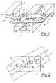
- a profile strip 1which can be fastened to a wall or ceiling in a manner not shown here is provided on its side facing away from the wall or ceiling with a longitudinally extending, undercut groove 2, into which a holder 3 is inserted.
- two extensions 5are arranged, which are punched out of the flat base part 6 - which can be made of sheet metal, for example - and bent out essentially in an L-shape.
- the two extensions 5lie opposite one another with respect to the groove 2 and are laterally offset by the width of their support surfaces 8 which essentially lie against the groove edges 7. This makes it easy to fix the holder 3 with respect to the profile strip 1 by inserting the extensions 5 into the groove - see also FIG. 2 - and rotating the holder 3 into that in FIG. 1 shown position possible.
- the holder 3can also be rotated in the covering plane by means of a screwdriver or a similar suitable tool, which can be inserted into the slot 9 in the central region 4.
- tabs 12are punched out of the flat base part 6 and bent out in an essentially L-shaped manner towards the side of the base part 6 opposite the extensions 5. 1, these tabs are provided in pairs in the outer regions 11 and serve to hold a wall or ceiling covering, of which only a covering part 13 which has not yet been used is shown.
- This trim part 13has a holding area 14 with a groove 15 into which the bent end areas of the tabs 12 engage, the holding area 14 or here the outer edge of the trim part 13 remaining next to the groove 15 abutting the supporting surfaces 16 of the tabs 12.
- the mutual distance between two, in the illustration of Fig. 1 from behind and from the front inserted into the tab 12 cladding partsis thus directly determined by the distance 17 of the support surfaces 16 of the respective tabs 12, so that in this regard, a variety of applications of the holder Attachment can be covered.
- the holder 3 shown in Fig. 2differs 1 essentially only in that here only one flap 12, which is assigned to the side-by-side (not shown) cladding parts, is arranged in the two opposite outer regions 11 of the holder 3, the support surfaces 16, which here perpendicular to Stand plane and are covered by the bent end areas of the tabs 12, only have a distance corresponding to the material thickness of the tabs 12 in this area.
Landscapes
- Engineering & Computer Science (AREA)
- Architecture (AREA)
- Civil Engineering (AREA)
- Structural Engineering (AREA)
- Finishing Walls (AREA)
- Connection Of Plates (AREA)
Abstract
Description
Translated fromGermanDie Erfindung betrifft eine Befestigung für eine Wand- bzw. Deckenverkleidung, mit an der Wand bzw. Decke befestigten Profilleisten, die an ihrer der Wand bzw. Decke abgekehrten Seite zumindest eine in ihrer Längsrichtung verlaufende, hinterschnittene Nut aufweisen, in die Halter eingesetzt sind, welche die Verkleidung haltende Lappen sowie jeweils zwei einander bezüglich der Nut gegenüberliegende, im Mittelbereich der Halter angeordnete und sich in der Nut abstützende Fortsätze aufweisen und durch Verdrehen in der Verkleidungsebene von der Nut bzw. der Verkleidung lösbar sind, wobei zwei, nebeneinanderliegenden Verkleidungsteilen zugeordnete, zusammengehörige Lappen in einem dem gewünschten Abstand der im montierten Zustand im wesentlichen seitlich an ihren Stützflächen anliegenden Haltebereiche der Verkleidungsteile entsprechenden Abstand angeordnet und die Stützflächen der Lappen senkrecht zu den zumindest um ihre eigene Breite seitlich versetzten Stützflächen der Fortsätze sind.The invention relates to a fastening for a wall or ceiling covering, with profile strips fastened to the wall or ceiling, which have at least one undercut groove running in their longitudinal direction on their side facing away from the wall or ceiling, into which holders are inserted, which have tabs holding the cladding and in each case two projections which lie opposite one another with respect to the groove, are arranged in the central region of the holders and are supported in the groove and can be detached from the groove or the cladding by twisting in the cladding plane, two cladding parts which are assigned adjacent to one another, Associated tabs are arranged at a distance corresponding to the desired distance of the holding areas of the cladding parts essentially lying laterally against their supporting surfaces in the assembled state, and the supporting surfaces of the tabs are perpendicular to the supporting surfaces which are offset laterally at least by their own width Extensions are.
Derartige Befestigungen sind beispielsweise aus der AT-PS 374 872 bekannt und haben den Vorteil, daß die einzelnen Halter für die üblicherweise aus Brettern, Tafeln oder dergleichen bestehende Verkleidung an beliebiger Stelle der Nut in diese eingebracht und durch Verdrehen befestigt werden können, wodurch die Montage sehr vereinfacht wird. Bei der genannten bekannten Ausführung gehen sowohl die mit der Nut zusammenwirkenden Fortsätze als auch die die Verkleidung haltenden Lappen vom Mittelbereich der Halter aus, wobei zur weiteren Erleichterung der Montage die Fortsätzebezogen auf die Ebene der Verkleidung - schräg zu den Lappen verlaufen. Nachteilig bei dieser Ausführung ist einerseits die relativ aufwendige Herstellung der Halter und andererseits der Umstand, daß die Verkleidung im Bereich von Stößen nicht einwandfrei an den Profilleisten festgelegt werden kann, da die einzelnen Halter zufolge der genannten Ausbildung ihrer Lappen nicht dazu geeignet sind, gleichzeitig zwei an einem Stoß aneinanderliegende Verkleidungsteile sicher zu fixieren, wodurch sich nur eine relativ geringe Anzahl von Befestigungsvarianten mit derartigen Haltern ergibt.Such fastenings are known for example from AT-PS 374 872 and have the advantage that the individual holders for the cladding, which usually consists of boards, boards or the like, can be introduced at any point in the groove and fastened by twisting, whereby the assembly is very simplified. In the known embodiment mentioned, both the extensions cooperating with the groove and the tabs holding the cladding extend from the central region of the holder, the projections relating to the level of the cladding extending obliquely to the tabs to further facilitate assembly. A disadvantage of this design is the relatively complex manufacture of the holder and on the other hand the fact that the cladding in the area of bumps cannot be properly fixed on the profile strips, since the individual holders are not suitable, due to the above-mentioned design of their rags, for securely fixing two cladding parts lying against one another at the same time, which only results in results in a relatively small number of fastening variants with such holders.
Aufgabe der vorliegenden Erfindung ist est, die genannten Nachteile der bekannten Anordnung zu vermeiden und insbesonders eine Befestigung der eingangs genannten Art so auszubilden, daß sich einerseits eine gegenüber dem angeführten Stand der Technik wesentlich vereinfachte Herstellung der Halter und andererseits eine größere Vielfalt im Hinblick auf die möglichen Befestigungsvarianten ergibt, wobei insbesonders auf einfache und zweckmäßige Weise und unter Beibehaltung einer einfachen Montage eine sichere Festlegung der Verkleidung auch im Bereich von Stößen möglich sein soll.The object of the present invention is to avoid the above-mentioned disadvantages of the known arrangement and, in particular, to design a fastening of the type mentioned at the outset in such a way that, on the one hand, manufacture of the holder is considerably simplified compared to the state of the art and, on the other hand, a greater variety with regard to possible fastening variants results, in particular in a simple and expedient manner and while maintaining simple installation, a secure fixing of the cladding should also be possible in the area of impacts.
Dies wird gemäß der Erfindung dadurch erreicht, daß jeder Halter einen ebenen Basisteil aufweist, der im montierten Zustand der Verkleidung zwischen der Profilleiste und der Verkleidung liegt, daß die Lappen und die Fortsätze sich aus dem ebenen Basisteil im wesentlichen L-förmig nach jeweils gegenüberliegenden Seiten des Basisteils erheben, daß jeweils zwei zusammengehörige Lappen in zwei voneinander beabstandeten und einander bezüglich der jeweiligen zumindest einen Nut gegenüberliegenden Außenbereichen des Basisteils angeordnet sind, und daß die von den im wesentlichen senkrecht zum Basisteil liegenden Schenkeln gebildeten Stützflächen der Fortsätze sich im montierten Zustand im wesentlichen an den Nuträndern abstützen. Durch die genannte Ausbildung ist auf sehr einfache und zweckmäßige Weise ein Halter geschaffen, der auch zwei an einem Stoß aneinanderliegende Teile der Verkleidung sicher halten kann, wobei darüberhinaus auch bei der normalen Verwendung zur Befestigung von zwei nebeneinanderliegenden Teilen der Verkleidung eine Verbesserung der Haltewirkung erzielt ist. Durch die seitliche Versetzung der sich bezüglich der Nut gegenüberliegenden Fortsätze kann der Halter nach wie vor sehr einfach durch Einstecken und Verdrehen in der Nut fixiert werden, wobei die richtige Endstellung im wesentlichen durch die Anlage der Stützflächen der Fortsätze an den Nuträndern gegeben ist.This is achieved according to the invention in that each holder has a flat base part, which lies in the assembled state of the panel between the profile strip and the panel, that the tabs and the extensions from the flat base part are substantially L-shaped on opposite sides of the base part raise that in each case two associated tabs are arranged in two outer regions of the base part which are spaced apart from one another and are opposite each other with respect to the respective at least one groove, and that the support surfaces of the extensions formed by the legs lying essentially perpendicular to the base part essentially extend in the assembled state Support on the edge of the groove. Through the aforementioned training, a holder is created in a very simple and expedient manner, which can also securely hold two parts of the cladding lying against one another, and moreover also during normal use Attachment of two adjacent parts of the panel an improvement in the holding effect is achieved. As a result of the lateral displacement of the projections opposite one another with respect to the groove, the holder can still be fixed very simply by inserting and twisting in the groove, the correct end position being essentially provided by the support surfaces of the projections resting on the groove edges.
Durch Variation des Abstands der den nebeneinanderliegenden Verkleidungsteilen zugeordneten Lappen kann unmittelbar der gegenseitige Abstand der Haltebereiche der Verkleidungsteile beeinflußt werden, was auf einfache Weise die Erzielung verschiedener Nutbreiten zwischen den nebeneinanderliegenden Verkleidungsteilen bzw. die Verwendung von mit unterschiedlich ausgestatteten Haltebereichen versehenen Verkleidungsteilen ermöglicht.By varying the spacing of the flaps assigned to the side-by-side cladding parts, the mutual distance between the holding areas of the cladding parts can be directly influenced, which in a simple manner enables different groove widths to be achieved between the side-by-side cladding parts or the use of cladding parts provided with differently equipped holding areas.
Die Halter können beispielsweise als gestanzte Blechteile ausgeführt sein, wobei die Lappen und die Fortsätze aus dem ebenen Basisteil jedes Halters ausgestanzt und im wesentlichen L-förmig nach jeweils gegenüberliegenden Seiten des Basisteils ausgebogen sind. Dies ermöglicht eine sehr einfache, zweckmäßige und kostengünstige Herstellung. Zusätzlich ist damit eine Verbesserung der Befestigung insofern erreicht, als nun die Festlegung der Halter in der Nut von der Festlegung der Verkleidungsteile am Halter unabhängig ist, womit sich engere Toleranzen und damit größere Sicherheiten und Genauigkeiten erzielen lassen als dies beispielsweise bei der eingangs angesprochenen bekannten Befestigung der Fall ist, bei welcher die Verkleidungsteile mittels der Lappen der Halter unmittelbar an die die Nut und damit die Halter selbst tragenden Profilleisten gedrückt werden.The holders can be designed, for example, as stamped sheet-metal parts, the tabs and the extensions being punched out of the flat base part of each holder and being bent out essentially in an L-shape toward opposite sides of the base part. This enables very simple, expedient and inexpensive production. In addition, an improvement in the fastening is achieved in that the fixing of the holder in the groove is now independent of the fixing of the trim parts on the holder, which allows tighter tolerances and thus greater security and accuracy than can be achieved, for example, in the known fastening mentioned above is the case in which the trim parts are pressed by means of the tabs of the holder directly onto the profile strips which support the groove and thus the holder itself.
Nach einer anderen Ausgestaltung der Erfindung ist vorgesehen, daß jeweils ein einzelner, nebeneinanderlie genden Verkleidungsteilen zugeordneter Lappen in zwei einander gegenüberliegenden Außenbereichen des Basisteiles angeordnet ist, weobei die Stützflächen dieser Lappen - bezogen auf eine Senkrechte zur Nut - einen der Materialstärke der Lappen in diesem Bereich entsprechenden Abstand aufweisen. Damit ist der Abstand der Haltebereiche an den nebeneinanderliegenden Verkleidungsteilen auf das unumgängliche Minimum reduziert, sodaß auch bei einfach seitlich mit einer Haltenut versehenen Verkleidungsteilen eine praktisch geschlossene Oberfläche der gesamten Verkleidung erzielbar ist.According to another embodiment of the invention, it is provided that a single, side by side lie lugs assigned to the covering parts are arranged in two mutually opposite outer regions of the base part, the supporting surfaces of these lobes being at a distance corresponding to the material thickness of the lobes in this region, based on a perpendicular to the groove. The distance between the holding areas on the side-by-side cladding parts is thus reduced to the inevitable minimum, so that a practically closed surface of the entire cladding can be achieved even with cladding parts simply provided with a holding groove on the side.
Die Erfindung wird im folgenden anhand der in der Zeichnung dargestellten Ausführungsbeispiele näher erläutert.
- Fig. 1 zeigt eine Schrägansicht eines Teils einer erfindungsgemäßen Befestigung und
- Fig. 2 zeigt eine Draufsicht auf einen in die Nut einer Profilleiste eingesetzten Halter eines anderen Ausführungsbeispiels.
- Fig. 1 shows an oblique view of part of a fastening according to the invention and
- Fig. 2 shows a plan view of a holder inserted in the groove of a profile strip of another embodiment.
Gemäß Fig. 1 ist eine auf hier nicht weiter dargestellte Weise an einer Wand bzw. Decke befestigbare Profilleiste 1 an ihrer der Wand bzw. Decke abgekehrten Seite mit einer in Längsrichtung verlaufenden, hinterschnittenen Nut 2 versehen, in die ein Halter 3 eingesetzt ist. Im Mittelbereich 4 des Halters 3 sind zwei Fortsätze 5 angeordnet, die aus dem ebenen Basisteil 6 - der beispielsweise aus Blech bestehen kann - ausgestanzt und im wesentlichen L-förmig ausgebogen sind. Die beiden Fortsätze 5 liegen sich bezüglich der Nut 2 gegenüber und sind um die Breite ihrer im wesentlichen an den Nuträndern 7 anliegenden Stützflächen 8 seitlich versetzt. Damit ist auf einfache Weise eine Festlegung des Halters 3 gegenüber der Profilleiste 1 durch Einsetzen der Fortsätze 5 in die Nut - siehe dazu auch Fig. 2 - und Verdrehen des Halters 3 in die in Fig. 1 dargestellte Stellung möglich. Die Verdrehung des Halters 3 in der Verkleidungsebene kann auch mittels eines Schraubenziehers oder eines ähnlichen geeigneten Werkzeugs erfolgen, welches in den Schlitz 9 im Mittelbereich 4 eingesteckt werden kann.1, a profile strip 1 which can be fastened to a wall or ceiling in a manner not shown here is provided on its side facing away from the wall or ceiling with a longitudinally extending, undercut
Im festgelegten Zustand des Halters 3 - wie er in Fig. 1 dargestellt ist - ist also der Basisteil 6 mittels der abgeknickten Endbereiche der Fortsätze 5, welche gegen die inneren Halteflächen 10 der Nut 2 drücken, gegen die Profilleiste 1 verspannt, wobei die richtige Winkelstellung in der Verkleidungsebene von den Stützflächen 8 der Fortsätze 5 bzw. deren Anlage an den Nuträndern 7 bestimmt wird.In the fixed state of the holder 3 - as shown in FIG. 1 - the
In zwei voneinander beabstandeten und sich bezüglich der Nut 2 gegenüberliegenden Außenbereichen 11 des Halters 3 sind Lappen 12 aus dem ebenen Basisteil 6 ausgestanzt und im wesentlichen L-förmig nach der den Fortsätzen 5 gegenüberliegenden Seite des Basisteils 6 ausgebogen. Diese Lappen sind nach Fig. 1 jeweils paarweise in den Außenbereichen 11 vorgesehen und dienen zum Halten einer Wand- bzw. Deckenverkleidung, von der hier nur ein noch nicht eingesetzter Verkleidungsteil 13 dargestellt ist. Dieser Verkleidungsteil 13 weist einen Haltebereich 14 mit einer Nut 15 auf, in welche die abgeknickten Endbereiche der Lappen 12 eingreifen, wobei der Haltebereich 14 bzw. hier die neben der Nut 15 verbleibende Außenkante des Verkleidungsteils 13, an den Stützflächen 16 der Lappen 12 anliegt. Der gegenseitige Abstand zweier, in der Darstellung nach Fig. 1 von hinten und von vorne in die Lappen 12 eingeschobener Verkleidungsteile ist damit unmittelbar bestimmt vom Abstand 17 der Stützflächen 16 der jeweils zusammengehörigen Lappen 12, sodaß mittels diesbezüglich unterschiedlich ausgeführten Haltern eine Vielzahl von Anwendungsbereichen der Befestigung abgedeckt werden kann.In two
Der in Fig. 2 dargestellte Halter 3 unterscheidet sich von dem nach Fig. 1 im wesentlichen nur dadurch, daß hier nun jeweils nur ein, den nebeneinanderliegenden (hier nicht dargestellten) Verkleidungsteilen zugeordneter Lappen 12 in den beiden gegenüberliegenden Außenbereichen 11 des Halters 3 angeordnet ist, wobei die Stützflächen 16, die hier senkrecht zur Zeichenebene stehen und von den abgeknickten Endbereichen der Lappen 12 verdeckt sind, nur mehr einen der Materialstärke der Lappen 12 in diesem Bereiche entsprechenden Abstand aufweisen.The
Nachdem der Halter 3 in der in Fig. 2 dargestellten Stellung relativ zur Profilleiste 1 mit den Fortsätzen 5 in die Nut 2 eingesetzt wurde, wird die Befestigung bzw. Festlegung in der Nut 2 durch Verdrehung in Richtung des Pfeils 18 herbeigeführt - es ergibt sich dann wieder eine Endlage wie in Fig. 1. Wenn dann beispielsweise zwei Verkleidungsteile 13 gemäß Fig. 1 in die Lappen 12 gemäß Fig. 2 eingeschoben werden, so werden die Haltebereiche 14 bzw. die Ränder der Verkleidungsteile 13 einen sehr kleinen und nur mehr durch die genannte Materialstärke der Lappen 12 im Bereich der Stützflächen 16 bedingten Abstand aufweisen.After the
Es ist hier noch darauf hinzuweisen, daß die Darstellung in der Zeichnung schematisch ist und daß insbesonders die Form der Fortsätze und Lappen bedingt durch spezielle Anforderungen, etwa des Stanzvorganges, auch von der dargestellten abweichen kann.It should also be pointed out here that the representation in the drawing is schematic and that, in particular, the shape of the extensions and tabs can also deviate from that shown due to special requirements, such as the punching process.
Claims (2)
Translated fromGermanApplications Claiming Priority (2)
| Application Number | Priority Date | Filing Date | Title |
|---|---|---|---|
| AT1637/87 | 1987-06-29 | ||
| AT163787 | 1987-06-29 |
Publications (2)
| Publication Number | Publication Date |
|---|---|
| EP0298070A2true EP0298070A2 (en) | 1989-01-04 |
| EP0298070A3 EP0298070A3 (en) | 1989-05-10 |
Family
ID=3517716
Family Applications (1)
| Application Number | Title | Priority Date | Filing Date |
|---|---|---|---|
| EP88890104AWithdrawnEP0298070A3 (en) | 1987-06-29 | 1988-04-28 | Fastening for a covering for a wall or celling |
Country Status (1)
| Country | Link |
|---|---|
| EP (1) | EP0298070A3 (en) |
Cited By (5)
| Publication number | Priority date | Publication date | Assignee | Title |
|---|---|---|---|---|
| FR2652843A1 (en)* | 1989-10-09 | 1991-04-12 | Emaillerie Alsacienne Cale Ind | Facade assembly |
| EP0643181A1 (en)* | 1993-08-14 | 1995-03-15 | Conrad-Plastics | Profile with a sliding claw positioned in a groove |
| AT399641B (en)* | 1990-06-27 | 1995-06-26 | Mesner Walter | Multipurpose profile system |
| ES2264302A1 (en)* | 2003-09-01 | 2006-12-16 | Proesga, S.L. | Fixing device for closures used on outer vertical sidewalls, has steel staples provided on vertical posts arranged at predetermined intervals on wall, in which steel staples have horizontal grooves to which pieces of ceramics are fitted |
| WO2012020093A3 (en)* | 2010-08-12 | 2012-04-05 | Kaindl Flooring Gmbh | Fastening element for fastening panels on an underlying surface, and combination of a terminating profile rail with a retaining element |
Family Cites Families (9)
| Publication number | Priority date | Publication date | Assignee | Title |
|---|---|---|---|---|
| US2620906A (en)* | 1947-01-30 | 1952-12-09 | Kawneer Co | Attaching clip for wall surfacing |
| US2857995A (en)* | 1955-12-21 | 1958-10-28 | Kawneer Co | Wall facing |
| GB912611A (en)* | 1958-04-02 | 1962-12-12 | Light Steel Sectional Const Lt | Improvements in or relating to means for fixing panels to metal frame members |
| DE1292355B (en)* | 1961-12-13 | 1969-04-10 | Frueh Friedrich | Connection of ceiling or wall panels, which are in contact with a flange of a carrier that protrudes on both sides and butted there, with the carrier |
| NL6917168A (en)* | 1969-11-14 | 1971-05-18 | ||
| DK132561C (en)* | 1972-03-22 | 1976-05-31 | Johansen Joergen Skoubo | CEILING OR WALL COVERING |
| AT374872B (en)* | 1979-06-28 | 1984-06-12 | Tranker Kurt | FASTENING FOR A WALL OR CEILING COVERING |
| DE3036474C2 (en)* | 1980-09-27 | 1986-03-13 | Lothar Ludwig 8711 Prichsenstadt Strobl | False ceiling |
| EP0124886B1 (en)* | 1983-05-06 | 1991-07-31 | Eugen Baumgärtner | Wall or ceiling covering |
- 1988
- 1988-04-28EPEP88890104Apatent/EP0298070A3/ennot_activeWithdrawn
Cited By (6)
| Publication number | Priority date | Publication date | Assignee | Title |
|---|---|---|---|---|
| FR2652843A1 (en)* | 1989-10-09 | 1991-04-12 | Emaillerie Alsacienne Cale Ind | Facade assembly |
| AT399641B (en)* | 1990-06-27 | 1995-06-26 | Mesner Walter | Multipurpose profile system |
| EP0643181A1 (en)* | 1993-08-14 | 1995-03-15 | Conrad-Plastics | Profile with a sliding claw positioned in a groove |
| ES2264302A1 (en)* | 2003-09-01 | 2006-12-16 | Proesga, S.L. | Fixing device for closures used on outer vertical sidewalls, has steel staples provided on vertical posts arranged at predetermined intervals on wall, in which steel staples have horizontal grooves to which pieces of ceramics are fitted |
| ES2264302B1 (en)* | 2003-09-01 | 2007-11-16 | Proesga, S.L. | DEVICE FOR FIXING CLOSURES TO EXTERNAL VERTICAL PARAMENTS. |
| WO2012020093A3 (en)* | 2010-08-12 | 2012-04-05 | Kaindl Flooring Gmbh | Fastening element for fastening panels on an underlying surface, and combination of a terminating profile rail with a retaining element |
Also Published As
| Publication number | Publication date |
|---|---|
| EP0298070A3 (en) | 1989-05-10 |
Similar Documents
| Publication | Publication Date | Title |
|---|---|---|
| DE3137426A1 (en) | POSTS FOR THE INSTALLATION OF A PARTITION | |
| DE69511676T2 (en) | Shelf arrangement | |
| DE60306959T2 (en) | METHOD FOR PRODUCING A HOLDING PLATE AND CUTTING AND RELATED HOLDING PLATE | |
| DE3434999C2 (en) | Support grid for a suspended ceiling | |
| DE19637835A1 (en) | Snap lock for flush mounted panels | |
| DE2642167A1 (en) | ADJUSTABLE CROSS BEAM ASSEMBLY | |
| DE2104050B2 (en) | Clamp bracket | |
| DE2164991A1 (en) | ANCHOR RAIL | |
| DE2814656A1 (en) | Trim fixture for vehicle interior - has rear projecting pins and hooks aligned with recesses in wall | |
| EP0298070A2 (en) | Fastening for a covering for a wall or celling | |
| AT391510B (en) | RAIL FOR HANGED CEILINGS | |
| DE2950745A1 (en) | CLAMP FOR AN ACCESSIBLE REMOVABLE SUPPORTING SYSTEM OF A WALL PANELING CONSISTING OF PANELS | |
| DE2553109A1 (en) | Grooved-batten wall or ceiling cladding fixture - has lugs on retainers in outside groove holding cladding in position | |
| DE69815904T2 (en) | Clamp connection element for connecting two wall profiles together | |
| AT1705U1 (en) | DRAWER RAIL AND METHOD FOR THE PRODUCTION THEREOF | |
| EP0465904B1 (en) | Ceiling cladding | |
| DE2843457C2 (en) | Wallcovering | |
| DE2720051C3 (en) | Grating | |
| EP0292667B1 (en) | Set of construction elements, especially for a wooden cabin | |
| DE1292355B (en) | Connection of ceiling or wall panels, which are in contact with a flange of a carrier that protrudes on both sides and butted there, with the carrier | |
| EP2050893A2 (en) | Cladding element for façades of buildings | |
| DE29707969U1 (en) | Cladding for a flat radiator | |
| DE4105186C2 (en) | Holding elements for plate-shaped components | |
| EP0397293B1 (en) | Fixing rail for sheets with trapezoidal corrugations for structural engineering | |
| EP0643181A1 (en) | Profile with a sliding claw positioned in a groove |
Legal Events
| Date | Code | Title | Description |
|---|---|---|---|
| PUAI | Public reference made under article 153(3) epc to a published international application that has entered the european phase | Free format text:ORIGINAL CODE: 0009012 | |
| AK | Designated contracting states | Kind code of ref document:A2 Designated state(s):BE CH DE FR GB IT LI LU NL SE | |
| PUAL | Search report despatched | Free format text:ORIGINAL CODE: 0009013 | |
| AK | Designated contracting states | Kind code of ref document:A3 Designated state(s):BE CH DE FR GB IT LI LU NL SE | |
| 17P | Request for examination filed | Effective date:19891110 | |
| 17Q | First examination report despatched | Effective date:19901109 | |
| STAA | Information on the status of an ep patent application or granted ep patent | Free format text:STATUS: THE APPLICATION IS DEEMED TO BE WITHDRAWN | |
| 18D | Application deemed to be withdrawn | Effective date:19910320 |