EP0297894A2 - Thermal package for electronic components - Google Patents
Thermal package for electronic componentsDownload PDFInfo
- Publication number
- EP0297894A2 EP0297894A2EP88305992AEP88305992AEP0297894A2EP 0297894 A2EP0297894 A2EP 0297894A2EP 88305992 AEP88305992 AEP 88305992AEP 88305992 AEP88305992 AEP 88305992AEP 0297894 A2EP0297894 A2EP 0297894A2
- Authority
- EP
- European Patent Office
- Prior art keywords
- heat
- support plate
- spreader
- printed circuit
- interconnect substrate
- Prior art date
- Legal status (The legal status is an assumption and is not a legal conclusion. Google has not performed a legal analysis and makes no representation as to the accuracy of the status listed.)
- Granted
Links
Images


Classifications
- H—ELECTRICITY
- H01—ELECTRIC ELEMENTS
- H01L—SEMICONDUCTOR DEVICES NOT COVERED BY CLASS H10
- H01L23/00—Details of semiconductor or other solid state devices
- H01L23/34—Arrangements for cooling, heating, ventilating or temperature compensation ; Temperature sensing arrangements
- H01L23/40—Mountings or securing means for detachable cooling or heating arrangements ; fixed by friction, plugs or springs
- H—ELECTRICITY
- H01—ELECTRIC ELEMENTS
- H01L—SEMICONDUCTOR DEVICES NOT COVERED BY CLASS H10
- H01L2924/00—Indexing scheme for arrangements or methods for connecting or disconnecting semiconductor or solid-state bodies as covered by H01L24/00
- H01L2924/0001—Technical content checked by a classifier
- H01L2924/0002—Not covered by any one of groups H01L24/00, H01L24/00 and H01L2224/00
Definitions
- This inventionrelates generally to the field of packaging for electronic components such as semiconductor chips and, more particularly, to packaging which serves as a sink for heat generated by the chips.
- chipsintegrated semiconductor components
- the new chipsare able to perform more complex functions, and at a faster rate, than their predecessors, yet are often the same size, or smaller.
- the new chipsconsume more power than their predecessors and, as a consequence, generate more heat. This is significant because most chips should be operated below 100°C. If a chip becomes too hot, the semiconductor junctions, which constitute the basic electrical elements within the chip, have a tendency to break down and the chip may malfunction. Thus, it is necessary to efficiently extract the heat, or otherwise cool the chips, while they are operating to insure that they continue to function properly.
- Thermal packageshave been provided for chips which, in addition to providing chips with protection, include a means for extracting the heat generated by the chips.
- Inside the chamberis some type of heat transfer device, such as pistons or other members formed of thermally conductive material, that are each in contact with a seperate chip and are all in contact with an external heat sink.
- the external heat sinkusually comprises either a set of cooling fins that are integral with the outer surface of the package, or a cold plate with liquid circulating therethrough. The heat generated by the chips is extracted by the heat sink through the heat transfer devices.
- the heat transfer deviceIn order for heat to readily flow from the chip through the heat transfer device, there should be a minimal amount of thermal resistance between the chip and the heat transfer device. Consequently, the heat transfer device must be in physical contact with the chip.
- Many thermal packagesare provided with heat transfer devices that are biased against the adjacent chips by springs or other mechanical devices. These devices thus exert a stress-inducing force on the chip. This stress may be aggravated due to the repetitive thermal expansion and contraction of the heat transfer device as the quantity of heat passing through it varies, causing the heat transfer devices to expand and contract at a rates different than those of the chips they are in contact with.
- the heat transfer devicesmay further stress the chips they are in contact with by imparting external strains and transmitting mechanical vibrations.
- the heat transfer devicesshould be in good physical contact with the external heat sink in order to maintain good thermal conductivity therebetween.
- many thermal packagesare integral assemblies wherein the chip, the heat transfer device and the external heat sink cannot be readily disassembled from each other. This type of assembly makes it difficult to perform maintenance on just one part of the package. For instance, if a chip in the package malfunctions, it may be difficult to gain access to it so it may be replaced, and so the entire package may have to be replaced. This situation would add to the overall cost of operating a device that contains this type of thermal package.
- Another consideration in the packaging of semiconductor chipsis that frequently the chips attached to a particular circuit generating the same amount heat are subjected to differing cooling conditions. This may be because of their locations in the circuit that they are part of. For instance, a chip closer to a cooling source, such as a fan or an opening, may operate at lower temperature than a chip further away. When this occurs, signal transmission between chips may be degraded because of differing voltage levels and noise margins on the chips as a result of their being operated at substantially different temperatures.
- a cooling sourcesuch as a fan or an opening
- This inventionprovides a new and improved thermal package for semiconductor chips.
- the thermal package of this inventionincludes one or more chips mounted on a printed circuit interconnect substrate and are attached there to by flexible leads, such as Tape Automated Bonding, (TAB), leads.
- a pliant foam padis attached to the surface of each chip adjacent the printed circuit interconnect substrate.
- a heat spreaderis attached to the top of each of the chips above the printed circuit interconnect substrate. The heat spreaders are secured to a support plate that is mounted above the printed circuit interconnect substrate.
- a heat sinksuch as a cap with cooling fins, or a cold plate, is attached to the top surface of the support plate.
- the heat spreaderis made of a material that has good thermal conductivity characteristics and the substantially same thermal coefficient of expansion as the chips.
- the heat spreadersare mounted in bores formed in the support plate, and secured therein by a ring and clamp assembly that biases the top of the heat spreaders against the heat sink.
- Electrical conductorsare provided on the surface of the support plate adjacent the printed circuit interconnect substrate.
- the heat spreadershave conductors on their outer surfaces that provide an electrical connection between the support plate conductors and electrical bond points on the top surface of the chips.
- the chips thereinare protected from external forces.
- a voltagecan be supplied to the chips through the conductors in the support plate and the heat spreader. Since the chips are firmly attached to the heat spreader, and the heat spreader is urged against the external heat sink, heat generated by the chips readily flows through the heat spreader to the external heat sink.
- each chipis provided with an individual heat spreader that efficiently conducts heat away therefrom towards the heat sink regardless of its position in the thermal package.
- Each heat spreaderoperates independently of the others, so that chip to chip temperature differences can be minimized. As a result, subsequent voltage and,noise variations between the chips can similarly be reduced.
- the heat spreadersdo not exert any substantial stress on the chips. This is because the heat spreaders and chips are attached together and the clamp and ring assembly biases the chip-and-heat spreader sub-assembly away from the printed circuit interconnect substrate. Any movement by the chip and heat spreader sub-assembly relative to the printed circuit interconnect substrate is tolerated by the flexibility of the TAB leads.
- the individual heat spreaderswill each be in physical contact with the surface of the heat sink regardless of any planarity variations of the heat sink surface.
- the heat spreaderSince the heat spreader is normally biased against the heat sink, the two do not have to be attached together with permanent fasteners in order to maintain firm physical contact, and good thermal transfer characteristics therebetween.
- Fastenerssuch as screws, can be used to attach the heat sink to the thermal package. This makes it possible to assemble this thermal package so it can be readily taken apart if it is necessary to perform maintenance or replace the chips therein.
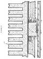
- FIG. 1illustrates a thermal package 10 constructed in accordance with this invention which contains a number of chips 12 mounted on a printed circuit interconnect substrate 14.
- the printed circuit board 14is affixed to base plate 16 which is formed of a material which matches the thermal coefficient of expansion of the printed circuit interconnect substrate 14, such as a polyimide-copper composite.
- Heat spreaders 18, each with a substantially cylindrical profile and a planar top surface 19,are attached to the major surfaces of the chips 12 above the printed circuit board 14.
- the heat spreaders 18are secured to a support plate 20, with a planar top surface 21, that forms a number of spreader bores 24 to accommodate the individual heat spreaders 18.
- An external heat sinksuch as a cooling fin plate 28, having a planar bottom surface 30, is attached to support plate 20 so the heat sink bottom surface 30 abuts the spreader top surfaces 19.
- each chip 12is provided with a pliant foam pad 32 that is affixed to the surface of the chip 12 on which the components are formed, the active surface, which is adjacent the printed circuit interconnect substrate 14.
- Tape Automated Bonding, (TAB)leads 33, formed on a section of film 35, which are relatively flexible, electrically connect bond points on the chip 12 (not illustrated) to conductors on the printed circuit board 14.
- Each heat spreader 18is formed from a ceramic or other material with good thermal conductivity characteristics and the same thermal coefficient of expansion as the chip 12 it is attached to.
- One type of material that the heat spreaders 18 may be formed fromis high thermal conductivity silicon-carbide ceramics.
- the heat spreader 18has a bottom planar surface 34 that the chip 12 is bonded to.
- the chips 12 and heat spreaders 18are bonded together by an adhesive 37 with good thermal conductivity characteristics, such as some epoxies or solder.
- the heat spreader bottom planar surface 34is part of a heat spreader bottom section 36 that subtends a cross-sectional area greater than that subtended by the main body of the heat spreader 18.
- the support plate 20is formed from a material, such as a beryllium-copper alloy, that has a thermal coefficient of thermal expansion identical to that of the cooling fin plate 28 and the base plate 16.
- a stepped annular lip 38, integral with the support plate 20,extends into each spreader bore 24 adjacent the printed circuit board 12.
- the annular lip 38defines a bottom opening 40 with a cross-sectional area less than that of the spreader bottom section 36.
- the chip 12 and heat spreader 18 subassemblyare secured to the support plate 20 by a clamp 41 and flex spring 42.
- the flex springshown more detail in Figure 3, has a coiled spring 43 encased within a rubber ring 44.
- the flex springis disposed around the heat spreader 18 above the annular lip 38 of the support plate 20.
- the clamp 41is a split-ring with a threaded space 46 used to accommodate an insertion tool.
- the clamp 41is secured to the outer circumference of the heat spreader 18 and disposed so the flex spring 42 is compressed between the clamp and the support plate annular lip 38.
- the threaded space 46includes a cam feature to facilitate the clamping action of the clamp 41 around the heat spreader 18.
- the surface of the support plate 20 proximate the printed circuit board 14is provided with one or more conductors 50 that extend to the bottom openings 40.
- the conductors 50may be insulated from the support plate 18 and each other by a polyimide film or other suitable insulator, (not illustrated).
- the conductors 50are electrically connected to associated spreader conductors 54 that have been deposited, utilizing suitable metalization techniques known in the art, onto the surface of the spreader bottom sections 36, including on the planar bottom surface 34.
- the electrical connection between support plate conductor 50 and the spreader conductor 54may be made using suitable compliant conductive member 55 such as electrical conductive elastomer section or metal springs.
- the spreader conductors 54are maintained in electrical contact with bond points on the major surface of the chips 12 through physical contact, soldering, or an electrically conductive adhesive.
- the printed circuit interconnect substrate 14is provided with a number of external leads 56 for electrically connecting the chips 12 to the circuit they are to be attached to.
- One or more openings, not illustrated,are provided in the base plate 16 to accommodate the leads 56.
- the thermal package 10may be assembled by first bonding the chips 12 to the spreader bottom sections 36 and the printed circuit interconnect substrate 14 to the base plate 16. Standard TAB bonding techniques are used to connect the chips 12 to the printed circuit interconnect substrate 14. The heat spreaders 18 are than attached to the top of the chips 12. The support plate 20 is then located over the heat spreaders 18, and the clamps 41 and flex springs 42 are inserted over the heat spreaders 18 to secure them to the support plate 20. The cooling fin 28, or other heat sink, may then be attached to the support plate top major surface 21.
- the thermal package 10may be assembled by first TAB bonding the chips 12 to the printed circuit interconnect substrate 14.
- the heat spreaders 18are then mounted to the support plate 20 with the clamp 41 and flex spring 42 subassembly.
- the heat spreaders 18 and support plate 20 subassemblyis then gang bonded to the chips 12.
- the chips 12 and printed circuit interconnect substrate 14are protected from external forces by the base plate 16, the support plate 20 and the cooling fin plate 28.
- a voltagemay be supplied to the chips 12 through the plate conductors 50 and the spreader conductors 54.
- the heat spreaders 18serve as heat transfer devices and heat generated by the chips 12 readily passes through them to the cooling fin plate 28.
- the flex springs 42urge the clamps 41 and heat spreaders 18 attached thereto away from the support plate bottom openings 40 so the heat spreader top surfaces 21 are biased against the heat sink bottom surface 30. Since the chips 12 are attached to the spreader bottom planar surfaces 34 and the heat spreaders are biased away from the printed circuit interconnect substrate 14, the heat spreaders 18 do not exert any force on the chips 12. Also, the chips 12 and heat spreaders 18 have the same coefficient of thermal expansion, so contraction or expansion of the chips 12 and heat spreaders 18 caused by changes in the heat flux therethrough will be identical. Therefore, the stress on the chips 12 caused by the contact of the heat spreaders 18 against them is minimal.
- each chip 12 housed in this package 10is attached to a separate heat spreader 18 that serves as a path for tthe efficient conducction of heat away therefrom regardless of its position in the package 10 so the temperature differences between the chips 12 will be minimized. As a result, subsequent voltage and noise variations between the chips, that are the result of temperature variations are similarly reduced.
- the thermal package 10when the thermal package 10 is assembled by first installing the chips 12 on the printed circuit interconnect substrate 14 and then mounting the heat spreaders 18 and support plate 20 subassembly to that subassembly, the heat spreaders 18 may be precisely positioned with respect to the support. This makes providing the electrical connection between the support plate conductors 50 and the spreader conductors 54 a relatively simple task. Also, this assembly process allows the use of standardized components and can be readily performed by automated assembly equipment resulting in economies cost of both components and assembly.
- the printed circuit interconnect substrate 14, the base plate 16, and the support plate 20have substantially identical coefficients of thermal expansion, these components will not stress each other as the heat generated by the chips 12 changes.
- thermal package 10Another advantage of this thermal package 10 is that the action of the clamps 41 and flex springs 42 biasing the heat spreaders 18 against the heat sink bottom planar surface insures there is good mechanical contact, and hence thermal conductivity between the heat spreaders 18 and the cooling fin plate 28. Since the heat spreaders 18 are normally biased against the cooling fin plate 28, the package can be assembled with fasteners, such as screws, that allow for the quick disassembly of the package 10. This makes repair and replacement of the portion of the thermal package 10 containing the chips 12 a relatively simple task. This is especially important if the thermal package 10 has a cold plate with recirculating coolant instead of a cooling fin plate 28 as a heat sink; the package 10 can be disassembled for repair without disconnecting the cold plate from its associated piping. Moreover, since the cooling fin plate 28, or other heat sink, is not rigidly attached to the package 10 it will not stress the package 10 as the heat generated by the chips 12 fluctuates.
- the clamps 41compress the flex spring's rubber rings 44 (Fig. 2) against the outer circumference of the heat spreaders 18 and the walls defining the spreader bores 24.
- the flex spring 42thus also serves as a seal to keep contaminates away from the chips 12 and printed circuit interconnect substrate 14.
- the foam pad 32, adjacent the active surface of the chip 12seals the components fabricated thereon so as to prevent their degradation due contact with environmental contaminants.
- thermal package 10is independent of the type of printed circuit interconnect substrate provided.
- the thermal packagemay be used to house and extract heat from a single chip as well as multiple chips. In some embodiments of the invention it may be desirable for reasons of design efficiency and economy to attach more than one chip to each heat spreader. Alternative methods of securing the heat spreaders 18 to the support plate so they are urged against the heat sink may be used.
- the thermal package 10may have more than one plate conductor 50 and spreader conductor 54 per chip 12 in order to supply multiple voltages thereto. Therefore, it is the object of the appended claims to cover all such variations and modifications as come within the true spirit and scope of the invention.
Landscapes
- Physics & Mathematics (AREA)
- Condensed Matter Physics & Semiconductors (AREA)
- General Physics & Mathematics (AREA)
- Engineering & Computer Science (AREA)
- Computer Hardware Design (AREA)
- Microelectronics & Electronic Packaging (AREA)
- Power Engineering (AREA)
- Cooling Or The Like Of Semiconductors Or Solid State Devices (AREA)
Abstract
Description
- This invention relates generally to the field of packaging for electronic components such as semiconductor chips and, more particularly, to packaging which serves as a sink for heat generated by the chips.
- Recent advances in semiconductor manufacturing technology have resulted in the increased miniaturization of integrated semiconductor components, generally known as "chips". The new chips are able to perform more complex functions, and at a faster rate, than their predecessors, yet are often the same size, or smaller. In order to perform these complex functions, the new chips consume more power than their predecessors and, as a consequence, generate more heat. This is significant because most chips should be operated below 100°C. If a chip becomes too hot, the semiconductor junctions, which constitute the basic electrical elements within the chip, have a tendency to break down and the chip may malfunction. Thus, it is necessary to efficiently extract the heat, or otherwise cool the chips, while they are operating to insure that they continue to function properly.
- Thermal packages have been provided for chips which, in addition to providing chips with protection, include a means for extracting the heat generated by the chips. Inside the chamber is some type of heat transfer device, such as pistons or other members formed of thermally conductive material, that are each in contact with a seperate chip and are all in contact with an external heat sink. The external heat sink usually comprises either a set of cooling fins that are integral with the outer surface of the package, or a cold plate with liquid circulating therethrough. The heat generated by the chips is extracted by the heat sink through the heat transfer devices.
- In order for heat to readily flow from the chip through the heat transfer device, there should be a minimal amount of thermal resistance between the chip and the heat transfer device. Consequently, the heat transfer device must be in physical contact with the chip. Many thermal packages are provided with heat transfer devices that are biased against the adjacent chips by springs or other mechanical devices. These devices thus exert a stress-inducing force on the chip. This stress may be aggravated due to the repetitive thermal expansion and contraction of the heat transfer device as the quantity of heat passing through it varies, causing the heat transfer devices to expand and contract at a rates different than those of the chips they are in contact with. Moreover, the heat transfer devices may further stress the chips they are in contact with by imparting external strains and transmitting mechanical vibrations. These stresses may occur both the normal operation of the devices or as a consequence of movement of the device such as in shipping or instillation. Over time the changes in mechanical stress may fatigue the chips so they are torn loose from the circuit they are attached to, break or are otherwise rendered useless..
- Furthermore, the heat transfer devices should be in good physical contact with the external heat sink in order to maintain good thermal conductivity therebetween. To provide the necessary contact, many thermal packages are integral assemblies wherein the chip, the heat transfer device and the external heat sink cannot be readily disassembled from each other. This type of assembly makes it difficult to perform maintenance on just one part of the package. For instance, if a chip in the package malfunctions, it may be difficult to gain access to it so it may be replaced, and so the entire package may have to be replaced. This situation would add to the overall cost of operating a device that contains this type of thermal package.
- Moreover, many new chips need to be supplied with a relatively high drain voltage level in order to insure their efficient operation. Normally this voltage is supplied by conductors on the printed circuit board to which the chip is attached. In a thermal package, the chip may be attached to a small-sized printed circuit board within the package that may not have sufficient space to accommodate the conductors necessary to supply the drain voltage.
- Another consideration in the packaging of semiconductor chips is that frequently the chips attached to a particular circuit generating the same amount heat are subjected to differing cooling conditions. This may be because of their locations in the circuit that they are part of. For instance, a chip closer to a cooling source, such as a fan or an opening, may operate at lower temperature than a chip further away. When this occurs, signal transmission between chips may be degraded because of differing voltage levels and noise margins on the chips as a result of their being operated at substantially different temperatures.
- This invention provides a new and improved thermal package for semiconductor chips.
- The thermal package of this invention includes one or more chips mounted on a printed circuit interconnect substrate and are attached there to by flexible leads, such as Tape Automated Bonding, (TAB), leads. A pliant foam pad is attached to the surface of each chip adjacent the printed circuit interconnect substrate. A heat spreader is attached to the top of each of the chips above the printed circuit interconnect substrate. The heat spreaders are secured to a support plate that is mounted above the printed circuit interconnect substrate. A heat sink, such as a cap with cooling fins, or a cold plate, is attached to the top surface of the support plate. The heat spreader is made of a material that has good thermal conductivity characteristics and the substantially same thermal coefficient of expansion as the chips.
- The heat spreaders are mounted in bores formed in the support plate, and secured therein by a ring and clamp assembly that biases the top of the heat spreaders against the heat sink.
- Electrical conductors are provided on the surface of the support plate adjacent the printed circuit interconnect substrate. The heat spreaders have conductors on their outer surfaces that provide an electrical connection between the support plate conductors and electrical bond points on the top surface of the chips.
- When the thermal package is assembled, the chips therein are protected from external forces. A voltage can be supplied to the chips through the conductors in the support plate and the heat spreader. Since the chips are firmly attached to the heat spreader, and the heat spreader is urged against the external heat sink, heat generated by the chips readily flows through the heat spreader to the external heat sink.
- Furthermore, each chip is provided with an individual heat spreader that efficiently conducts heat away therefrom towards the heat sink regardless of its position in the thermal package. Each heat spreader operates independently of the others, so that chip to chip temperature differences can be minimized. As a result, subsequent voltage and,noise variations between the chips can similarly be reduced.
- The heat spreaders do not exert any substantial stress on the chips. This is because the heat spreaders and chips are attached together and the clamp and ring assembly biases the chip-and-heat spreader sub-assembly away from the printed circuit interconnect substrate. Any movement by the chip and heat spreader sub-assembly relative to the printed circuit interconnect substrate is tolerated by the flexibility of the TAB leads.
- Moreover, the individual heat spreaders will each be in physical contact with the surface of the heat sink regardless of any planarity variations of the heat sink surface.
- Since the heat spreader is normally biased against the heat sink, the two do not have to be attached together with permanent fasteners in order to maintain firm physical contact, and good thermal transfer characteristics therebetween. Fasteners, such as screws, can be used to attach the heat sink to the thermal package. This makes it possible to assemble this thermal package so it can be readily taken apart if it is necessary to perform maintenance or replace the chips therein.
- This invention is pointed out with particularity in the appended claims. The above and further advantages of this invention may be better understood by referring to the following description taken in conjunction with the accompanying drawings, in which:
- Figure 1 is a top view, partially cut away, illustrating the thermal package of this invention.
- Figure 2 is a cross-sectional view of the thermal package of this invention with a chip mounted therein.
- Figure 3 is a cross-sectional illustration of a flex seal spring of Figure 2 used to bias the heat spreader towards the external heat sink according to this invention.
- Figure 1 illustrates a
thermal package 10 constructed in accordance with this invention which contains a number ofchips 12 mounted on a printedcircuit interconnect substrate 14. The printedcircuit board 14 is affixed tobase plate 16 which is formed of a material which matches the thermal coefficient of expansion of the printedcircuit interconnect substrate 14, such as a polyimide-copper composite.Heat spreaders 18, each with a substantially cylindrical profile and a planartop surface 19, are attached to the major surfaces of thechips 12 above the printedcircuit board 14. The heat spreaders 18 are secured to asupport plate 20, with a planartop surface 21, that forms a number of spreader bores 24 to accommodate theindividual heat spreaders 18. An external heat sink, such as a coolingfin plate 28, having aplanar bottom surface 30, is attached to supportplate 20 so the heatsink bottom surface 30 abuts the spreader top surfaces 19. - As depicted in Figure 2, each
chip 12 is provided with apliant foam pad 32 that is affixed to the surface of thechip 12 on which the components are formed, the active surface, which is adjacent the printedcircuit interconnect substrate 14. Tape Automated Bonding, (TAB), leads 33, formed on a section offilm 35, which are relatively flexible, electrically connect bond points on the chip 12 (not illustrated) to conductors on the printedcircuit board 14. - Each
heat spreader 18 is formed from a ceramic or other material with good thermal conductivity characteristics and the same thermal coefficient of expansion as thechip 12 it is attached to. One type of material that theheat spreaders 18 may be formed from is high thermal conductivity silicon-carbide ceramics. Theheat spreader 18 has a bottom planar surface 34 that thechip 12 is bonded to. Thechips 12 andheat spreaders 18 are bonded together by an adhesive 37 with good thermal conductivity characteristics, such as some epoxies or solder. The heat spreader bottom planar surface 34 is part of a heatspreader bottom section 36 that subtends a cross-sectional area greater than that subtended by the main body of theheat spreader 18. - The
support plate 20 is formed from a material, such as a beryllium-copper alloy, that has a thermal coefficient of thermal expansion identical to that of the coolingfin plate 28 and thebase plate 16. A steppedannular lip 38, integral with thesupport plate 20, extends into each spreader bore 24 adjacent the printedcircuit board 12. Theannular lip 38 defines abottom opening 40 with a cross-sectional area less than that of thespreader bottom section 36. Thechip 12 andheat spreader 18 subassembly are secured to thesupport plate 20 by aclamp 41 andflex spring 42. The flex spring, shown more detail in Figure 3, has a coiledspring 43 encased within a rubber ring 44. The flex spring is disposed around theheat spreader 18 above theannular lip 38 of thesupport plate 20. Theclamp 41 is a split-ring with a threadedspace 46 used to accommodate an insertion tool. Theclamp 41 is secured to the outer circumference of theheat spreader 18 and disposed so theflex spring 42 is compressed between the clamp and the support plateannular lip 38. The threadedspace 46 includes a cam feature to facilitate the clamping action of theclamp 41 around theheat spreader 18. - The surface of the
support plate 20 proximate the printedcircuit board 14 is provided with one ormore conductors 50 that extend to thebottom openings 40. Theconductors 50 may be insulated from thesupport plate 18 and each other by a polyimide film or other suitable insulator, (not illustrated). Theconductors 50 are electrically connected to associatedspreader conductors 54 that have been deposited, utilizing suitable metalization techniques known in the art, onto the surface of thespreader bottom sections 36, including on the planar bottom surface 34. The electrical connection betweensupport plate conductor 50 and thespreader conductor 54 may be made using suitable compliantconductive member 55 such as electrical conductive elastomer section or metal springs. Thespreader conductors 54 are maintained in electrical contact with bond points on the major surface of thechips 12 through physical contact, soldering, or an electrically conductive adhesive. - The printed
circuit interconnect substrate 14 is provided with a number of external leads 56 for electrically connecting thechips 12 to the circuit they are to be attached to. One or more openings, not illustrated, are provided in thebase plate 16 to accommodate the leads 56. - The
thermal package 10 may be assembled by first bonding thechips 12 to thespreader bottom sections 36 and the printedcircuit interconnect substrate 14 to thebase plate 16. Standard TAB bonding techniques are used to connect thechips 12 to the printedcircuit interconnect substrate 14. The heat spreaders 18 are than attached to the top of thechips 12. Thesupport plate 20 is then located over theheat spreaders 18, and theclamps 41 and flex springs 42 are inserted over theheat spreaders 18 to secure them to thesupport plate 20. The coolingfin 28, or other heat sink, may then be attached to the support plate topmajor surface 21. - Alternatively, the
thermal package 10 may be assembled by first TAB bonding thechips 12 to the printedcircuit interconnect substrate 14. The heat spreaders 18 are then mounted to thesupport plate 20 with theclamp 41 andflex spring 42 subassembly. The heat spreaders 18 andsupport plate 20 subassembly is then gang bonded to thechips 12. - When this
thermal package 10 is assembled, thechips 12 and printedcircuit interconnect substrate 14 are protected from external forces by thebase plate 16, thesupport plate 20 and the coolingfin plate 28. A voltage may be supplied to thechips 12 through theplate conductors 50 and thespreader conductors 54. The heat spreaders 18 serve as heat transfer devices and heat generated by thechips 12 readily passes through them to the coolingfin plate 28. - The flex springs 42 urge the
clamps 41 andheat spreaders 18 attached thereto away from the supportplate bottom openings 40 so the heat spreader top surfaces 21 are biased against the heatsink bottom surface 30. Since thechips 12 are attached to the spreader bottom planar surfaces 34 and the heat spreaders are biased away from the printedcircuit interconnect substrate 14, theheat spreaders 18 do not exert any force on thechips 12. Also, thechips 12 andheat spreaders 18 have the same coefficient of thermal expansion, so contraction or expansion of thechips 12 andheat spreaders 18 caused by changes in the heat flux therethrough will be identical. Therefore, the stress on thechips 12 caused by the contact of theheat spreaders 18 against them is minimal. Since afoam pad 32 is attached to each of thechips 12, and thechips 12 are connected to the printedcircuit interconnect substrate 14 by the flexible TAB leads 33, vertical and horizontal movement relative to the printedcircuit interconnect substrate 14 during installation, and due to thermal expansion and contraction, is tolerated. Thus, thechips 12 housed in thethermal package 10 are subject to virtually no mechanical stress that over time can cause the chips to become fatigued and rendered useless. - Also, each
chip 12 housed in thispackage 10 is attached to aseparate heat spreader 18 that serves as a path for tthe efficient condusction of heat away therefrom regardless of its position in thepackage 10 so the temperature differences between thechips 12 will be minimized. As a result, subsequent voltage and noise variations between the chips, that are the result of temperature variations are similarly reduced. - Furthermore, when the
thermal package 10 is assembled by first installing thechips 12 on the printedcircuit interconnect substrate 14 and then mounting theheat spreaders 18 andsupport plate 20 subassembly to that subassembly, theheat spreaders 18 may be precisely positioned with respect to the support. This makes providing the electrical connection between thesupport plate conductors 50 and the spreader conductors 54 a relatively simple task. Also, this assembly process allows the use of standardized components and can be readily performed by automated assembly equipment resulting in economies cost of both components and assembly. - Moreover, since the printed
circuit interconnect substrate 14, thebase plate 16, and thesupport plate 20 have substantially identical coefficients of thermal expansion, these components will not stress each other as the heat generated by thechips 12 changes. - Another advantage of this
thermal package 10 is that the action of theclamps 41 and flex springs 42 biasing theheat spreaders 18 against the heat sink bottom planar surface insures there is good mechanical contact, and hence thermal conductivity between theheat spreaders 18 and the coolingfin plate 28. Since theheat spreaders 18 are normally biased against the coolingfin plate 28, the package can be assembled with fasteners, such as screws, that allow for the quick disassembly of thepackage 10. This makes repair and replacement of the portion of thethermal package 10 containing the chips 12 a relatively simple task. This is especially important if thethermal package 10 has a cold plate with recirculating coolant instead of a coolingfin plate 28 as a heat sink; thepackage 10 can be disassembled for repair without disconnecting the cold plate from its associated piping. Moreover, since the coolingfin plate 28, or other heat sink, is not rigidly attached to thepackage 10 it will not stress thepackage 10 as the heat generated by thechips 12 fluctuates. - Furthermore, the
clamps 41 compress the flex spring's rubber rings 44 (Fig. 2) against the outer circumference of theheat spreaders 18 and the walls defining the spreader bores 24. Theflex spring 42 thus also serves as a seal to keep contaminates away from thechips 12 and printedcircuit interconnect substrate 14. Moreover, thefoam pad 32, adjacent the active surface of thechip 12 seals the components fabricated thereon so as to prevent their degradation due contact with environmental contaminants. - It is understood that this description is for the purposes of illustration only, and alternative embodiments of this invention are possible. For instance, as previously mentioned, a cold plate rather than the cooling
fin plate 28 can be used as the external heat sink. The operation of thethermal package 10 is independent of the type of printed circuit interconnect substrate provided. The thermal package may be used to house and extract heat from a single chip as well as multiple chips. In some embodiments of the invention it may be desirable for reasons of design efficiency and economy to attach more than one chip to each heat spreader. Alternative methods of securing theheat spreaders 18 to the support plate so they are urged against the heat sink may be used. Also, thethermal package 10 may have more than oneplate conductor 50 andspreader conductor 54 perchip 12 in order to supply multiple voltages thereto. Therefore, it is the object of the appended claims to cover all such variations and modifications as come within the true spirit and scope of the invention.
Claims (9)
Applications Claiming Priority (2)
| Application Number | Priority Date | Filing Date | Title |
|---|---|---|---|
| US07/069,406US4887147A (en) | 1987-07-01 | 1987-07-01 | Thermal package for electronic components |
| US69406 | 1987-07-01 |
Publications (3)
| Publication Number | Publication Date |
|---|---|
| EP0297894A2true EP0297894A2 (en) | 1989-01-04 |
| EP0297894A3 EP0297894A3 (en) | 1989-06-14 |
| EP0297894B1 EP0297894B1 (en) | 1994-11-02 |
Family
ID=22088776
Family Applications (1)
| Application Number | Title | Priority Date | Filing Date |
|---|---|---|---|
| EP88305992AExpired - LifetimeEP0297894B1 (en) | 1987-07-01 | 1988-06-30 | Thermal package for electronic components |
Country Status (5)
| Country | Link |
|---|---|
| US (1) | US4887147A (en) |
| EP (1) | EP0297894B1 (en) |
| JP (1) | JPS6489451A (en) |
| CA (1) | CA1282866C (en) |
| DE (1) | DE3851985T2 (en) |
Cited By (1)
| Publication number | Priority date | Publication date | Assignee | Title |
|---|---|---|---|---|
| US6570247B1 (en) | 1997-12-30 | 2003-05-27 | Intel Corporation | Integrated circuit device having an embedded heat slug |
Families Citing this family (24)
| Publication number | Priority date | Publication date | Assignee | Title |
|---|---|---|---|---|
| US6478356B1 (en)* | 2000-01-05 | 2002-11-12 | Mark Wayne | Cargo area structure |
| US5218215A (en)* | 1990-12-19 | 1993-06-08 | Vlsi Technology, Inc. | Semiconductor device package having a thermal dissipation means that allows for lateral movement of the lead frame with respect to the housing without breakage of the thermal dissipation path |
| US5162975A (en)* | 1991-10-15 | 1992-11-10 | Hewlett-Packard Company | Integrated circuit demountable TAB apparatus |
| US5262925A (en)* | 1991-10-15 | 1993-11-16 | Hewlett-Packard Company | Tab frame with area array edge contacts |
| US5504652A (en)* | 1994-09-16 | 1996-04-02 | Apple Computer, Inc. | Unitary heat sink for integrated circuits |
| US5548090A (en)* | 1995-08-21 | 1996-08-20 | Northern Telecom Limited | Heat sink and printed circuit board combination |
| US6323665B1 (en) | 1997-10-07 | 2001-11-27 | Reliability Incorporated | Apparatus capable of high power dissipation during burn-in of a device under test |
| IL135484A0 (en)* | 1997-10-07 | 2001-05-20 | Reliability Inc | Burn-in board with adaptable heat sink device |
| US6049217A (en)* | 1997-12-30 | 2000-04-11 | Intel Corporation | Thermally enhanced test contactor |
| US6072322A (en)* | 1997-12-30 | 2000-06-06 | Intel Corporation | Thermally enhanced test socket |
| US6545352B1 (en) | 2002-02-15 | 2003-04-08 | Ericsson Inc. | Assembly for mounting power semiconductive modules to heat dissipators |
| US6999317B2 (en)* | 2003-08-12 | 2006-02-14 | Delphi Technologies, Inc. | Thermally enhanced electronic module with self-aligning heat sink |
| US8686277B2 (en)* | 2004-12-27 | 2014-04-01 | Intel Corporation | Microelectronic assembly including built-in thermoelectric cooler and method of fabricating same |
| US7532474B2 (en)* | 2006-02-21 | 2009-05-12 | 3Com Corporation | Apparatus for dissipating heat from electronic components in an enclosed housing |
| US7679917B2 (en)* | 2007-02-02 | 2010-03-16 | Deck Joseph F | Electronic assembly cooling |
| JP2009059760A (en)* | 2007-08-30 | 2009-03-19 | Toshiba Corp | Electronic circuit board heat dissipation structure |
| DE102008028299B3 (en)* | 2008-06-13 | 2009-07-30 | Epcos Ag | System support for e.g. micro-electro-mechanical system component, has flexible support with upper side, and conductor paths guided to connecting contacts on upper side of components, which is turned away from flexible support |
| BR112012014093B1 (en) | 2009-12-09 | 2020-09-29 | Interdigital Ce Patent Holdings | ELECTRONIC DEVICE HAVING MICRO PERFORATIONS |
| BR112012021430A2 (en) | 2010-02-25 | 2020-07-14 | Thomson Licensing | miniature multi-layer radiant radiant cooling case with hidden quick release fasteners |
| CN103262675B (en) | 2010-05-19 | 2016-03-30 | 汤姆森特许公司 | The Set Top Box of energy dissipated heat load |
| KR20140061299A (en) | 2011-03-09 | 2014-05-21 | 톰슨 라이센싱 | Set top box or server having snap-in heat sink and smart card reader |
| EP2732684B1 (en) | 2011-07-14 | 2022-01-12 | Thomson Licensing | Set top box having snap-in heat sink and smart card reader with a hold down for retaining the heat sink |
| US11807381B2 (en)* | 2021-03-16 | 2023-11-07 | Rolls-Royce Corporation | Aircraft hybrid propulsion system including cold plate for a high density power converter |
| US20230262935A1 (en)* | 2022-01-26 | 2023-08-17 | Celsia Technologies Taiwan, Inc. | Heat dissipation device and anti-vibration heat conduction structure thereof |
Family Cites Families (8)
| Publication number | Priority date | Publication date | Assignee | Title |
|---|---|---|---|---|
| GB1327352A (en)* | 1971-10-02 | 1973-08-22 | Kyoto Ceramic | Semiconductor device |
| US4396935A (en)* | 1980-10-06 | 1983-08-02 | Ncr Corporation | VLSI Packaging system |
| JPS58169943A (en)* | 1982-03-29 | 1983-10-06 | Fujitsu Ltd | semiconductor equipment |
| JPS58173790A (en)* | 1982-04-06 | 1983-10-12 | シチズン時計株式会社 | Connection structure of display unit and semiconductor device |
| US4620215A (en)* | 1982-04-16 | 1986-10-28 | Amdahl Corporation | Integrated circuit packaging systems with double surface heat dissipation |
| US4479140A (en)* | 1982-06-28 | 1984-10-23 | International Business Machines Corporation | Thermal conduction element for conducting heat from semiconductor devices to a cold plate |
| EP0103068B1 (en)* | 1982-09-09 | 1989-01-04 | Siemens Aktiengesellschaft | Cooling device for a plurality of integrated components assembled as a flat structure |
| US4647959A (en)* | 1985-05-20 | 1987-03-03 | Tektronix, Inc. | Integrated circuit package, and method of forming an integrated circuit package |
- 1987
- 1987-07-01USUS07/069,406patent/US4887147A/ennot_activeExpired - Lifetime
- 1988
- 1988-06-30EPEP88305992Apatent/EP0297894B1/ennot_activeExpired - Lifetime
- 1988-06-30DEDE3851985Tpatent/DE3851985T2/ennot_activeExpired - Fee Related
- 1988-06-30CACA000570919Apatent/CA1282866C/ennot_activeExpired - Fee Related
- 1988-06-30JPJP63164096Apatent/JPS6489451A/enactiveGranted
Cited By (2)
| Publication number | Priority date | Publication date | Assignee | Title |
|---|---|---|---|---|
| US6570247B1 (en) | 1997-12-30 | 2003-05-27 | Intel Corporation | Integrated circuit device having an embedded heat slug |
| US6607928B1 (en)* | 1997-12-30 | 2003-08-19 | Intel Corporation | Integrated circuit device having an embedded heat slug |
Also Published As
| Publication number | Publication date |
|---|---|
| JPS6489451A (en) | 1989-04-03 |
| JPH0581185B2 (en) | 1993-11-11 |
| DE3851985T2 (en) | 1995-05-18 |
| EP0297894B1 (en) | 1994-11-02 |
| CA1282866C (en) | 1991-04-09 |
| EP0297894A3 (en) | 1989-06-14 |
| DE3851985D1 (en) | 1994-12-08 |
| US4887147A (en) | 1989-12-12 |
Similar Documents
| Publication | Publication Date | Title |
|---|---|---|
| US4887147A (en) | Thermal package for electronic components | |
| US4621304A (en) | Heat radiator assembly | |
| KR0156013B1 (en) | Heat sink and cover for tab integrated circuits | |
| US6180436B1 (en) | Method for removing heat from a flip chip semiconductor device | |
| US5184211A (en) | Apparatus for packaging and cooling integrated circuit chips | |
| US5920457A (en) | Apparatus for cooling electronic devices using a flexible coolant conduit | |
| KR100281500B1 (en) | Flexible cold plate having a one-piece coolant conduit and method employing same | |
| US5109317A (en) | Mounting mechanism for mounting heat sink on multi-chip module | |
| US5859764A (en) | Electronics package employing a high thermal performance wedgelock | |
| US5369879A (en) | Method of mounting a semiconductor device to a heat sink | |
| US7209354B2 (en) | Ball grid array package with heat sink device | |
| US5430611A (en) | Spring-biased heat sink assembly for a plurality of integrated circuits on a substrate | |
| US5870286A (en) | Heat sink assembly for cooling electronic modules | |
| US5615086A (en) | Apparatus for cooling a plurality of electrical components mounted on a printed circuit board | |
| US6212074B1 (en) | Apparatus for dissipating heat from a circuit board having a multilevel surface | |
| US5258887A (en) | Electrical device cooling system using a heat sink attached to a circuit board containing heat conductive layers and channels | |
| US6816378B1 (en) | Stack up assembly | |
| US5270902A (en) | Heat transfer device for use with a heat sink in removing thermal energy from an integrated circuit chip | |
| CA2139266C (en) | Semiconductor package | |
| EP0644593A2 (en) | Semiconductor module | |
| EP0625871A1 (en) | Electronic component heat sink attachment using a canted coil spring | |
| GB2279807A (en) | A heat sink assembly for a multi-chip module | |
| US6101094A (en) | Printed circuit board with integrated cooling mechanism | |
| US6700195B1 (en) | Electronic assembly for removing heat from a flip chip | |
| US5306866A (en) | Module for electronic package |
Legal Events
| Date | Code | Title | Description |
|---|---|---|---|
| PUAI | Public reference made under article 153(3) epc to a published international application that has entered the european phase | Free format text:ORIGINAL CODE: 0009012 | |
| AK | Designated contracting states | Kind code of ref document:A2 Designated state(s):CH DE FR GB IT LI NL SE | |
| PUAL | Search report despatched | Free format text:ORIGINAL CODE: 0009013 | |
| AK | Designated contracting states | Kind code of ref document:A3 Designated state(s):CH DE FR GB IT LI NL SE | |
| 17P | Request for examination filed | Effective date:19890906 | |
| 17Q | First examination report despatched | Effective date:19920430 | |
| GRAA | (expected) grant | Free format text:ORIGINAL CODE: 0009210 | |
| AK | Designated contracting states | Kind code of ref document:B1 Designated state(s):CH DE FR GB IT LI NL SE | |
| PG25 | Lapsed in a contracting state [announced via postgrant information from national office to epo] | Ref country code:NL Effective date:19941102 Ref country code:LI Effective date:19941102 Ref country code:CH Effective date:19941102 | |
| REF | Corresponds to: | Ref document number:3851985 Country of ref document:DE Date of ref document:19941208 | |
| ET | Fr: translation filed | ||
| ITF | It: translation for a ep patent filed | ||
| PG25 | Lapsed in a contracting state [announced via postgrant information from national office to epo] | Ref country code:SE Effective date:19950202 | |
| REG | Reference to a national code | Ref country code:CH Ref legal event code:PL | |
| NLV1 | Nl: lapsed or annulled due to failure to fulfill the requirements of art. 29p and 29m of the patents act | ||
| PLBE | No opposition filed within time limit | Free format text:ORIGINAL CODE: 0009261 | |
| STAA | Information on the status of an ep patent application or granted ep patent | Free format text:STATUS: NO OPPOSITION FILED WITHIN TIME LIMIT | |
| 26N | No opposition filed | ||
| PGFP | Annual fee paid to national office [announced via postgrant information from national office to epo] | Ref country code:FR Payment date:19980520 Year of fee payment:11 | |
| PGFP | Annual fee paid to national office [announced via postgrant information from national office to epo] | Ref country code:GB Payment date:19980526 Year of fee payment:11 | |
| PGFP | Annual fee paid to national office [announced via postgrant information from national office to epo] | Ref country code:DE Payment date:19980527 Year of fee payment:11 | |
| PG25 | Lapsed in a contracting state [announced via postgrant information from national office to epo] | Ref country code:GB Free format text:LAPSE BECAUSE OF NON-PAYMENT OF DUE FEES Effective date:19990630 Ref country code:FR Free format text:THE PATENT HAS BEEN ANNULLED BY A DECISION OF A NATIONAL AUTHORITY Effective date:19990630 | |
| GBPC | Gb: european patent ceased through non-payment of renewal fee | Effective date:19990630 | |
| PG25 | Lapsed in a contracting state [announced via postgrant information from national office to epo] | Ref country code:DE Free format text:LAPSE BECAUSE OF NON-PAYMENT OF DUE FEES Effective date:20000503 | |
| REG | Reference to a national code | Ref country code:FR Ref legal event code:ST | |
| PG25 | Lapsed in a contracting state [announced via postgrant information from national office to epo] | Ref country code:IT Free format text:LAPSE BECAUSE OF NON-PAYMENT OF DUE FEES;WARNING: LAPSES OF ITALIAN PATENTS WITH EFFECTIVE DATE BEFORE 2007 MAY HAVE OCCURRED AT ANY TIME BEFORE 2007. THE CORRECT EFFECTIVE DATE MAY BE DIFFERENT FROM THE ONE RECORDED. Effective date:20050630 |