EP0297309B1 - Process and device for metering and regulating the powder flow in a powder spray coating installation - Google Patents
Process and device for metering and regulating the powder flow in a powder spray coating installationDownload PDFInfo
- Publication number
- EP0297309B1 EP0297309B1EP88108891AEP88108891AEP0297309B1EP 0297309 B1EP0297309 B1EP 0297309B1EP 88108891 AEP88108891 AEP 88108891AEP 88108891 AEP88108891 AEP 88108891AEP 0297309 B1EP0297309 B1EP 0297309B1
- Authority
- EP
- European Patent Office
- Prior art keywords
- powder
- gas
- ray
- signal
- flow
- Prior art date
- Legal status (The legal status is an assumption and is not a legal conclusion. Google has not performed a legal analysis and makes no representation as to the accuracy of the status listed.)
- Expired - Lifetime
Links
- 239000000843powderSubstances0.000titleclaimsdescription87
- 238000005507sprayingMethods0.000titleclaimsdescription6
- 230000001105regulatory effectEffects0.000titleclaimsdescription5
- 229940098458powder sprayDrugs0.000titleclaimsdescription4
- 238000009434installationMethods0.000titleclaims2
- 238000000034methodMethods0.000title1
- 238000011156evaluationMethods0.000claimsdescription24
- 238000010586diagramMethods0.000claimsdescription7
- 239000000463materialSubstances0.000claimsdescription7
- 238000011144upstream manufacturingMethods0.000claimsdescription7
- 239000007921spraySubstances0.000claimsdescription6
- 230000001419dependent effectEffects0.000claimsdescription4
- 230000006870functionEffects0.000claimsdescription3
- 230000003313weakening effectEffects0.000claimsdescription3
- 239000007789gasSubstances0.000description118
- 230000005855radiationEffects0.000description51
- 238000005259measurementMethods0.000description4
- 238000009530blood pressure measurementMethods0.000description3
- 238000009826distributionMethods0.000description3
- 239000002245particleSubstances0.000description3
- 239000011248coating agentSubstances0.000description2
- 238000000576coating methodMethods0.000description2
- 230000000694effectsEffects0.000description2
- 239000012530fluidSubstances0.000description2
- 235000013599spicesNutrition0.000description2
- 241001261858AlsodesSpecies0.000description1
- 230000000052comparative effectEffects0.000description1
- 238000011109contaminationMethods0.000description1
- 238000013016dampingMethods0.000description1
- 210000003298dental enamelAnatomy0.000description1
- 239000011521glassSubstances0.000description1
- 239000008187granular materialSubstances0.000description1
- 230000001771impaired effectEffects0.000description1
- 239000002184metalSubstances0.000description1
- 239000000203mixtureSubstances0.000description1
- 230000002285radioactive effectEffects0.000description1
- 230000007363regulatory processEffects0.000description1
Images

Classifications
- B—PERFORMING OPERATIONS; TRANSPORTING
- B05—SPRAYING OR ATOMISING IN GENERAL; APPLYING FLUENT MATERIALS TO SURFACES, IN GENERAL
- B05B—SPRAYING APPARATUS; ATOMISING APPARATUS; NOZZLES
- B05B7/00—Spraying apparatus for discharge of liquids or other fluent materials from two or more sources, e.g. of liquid and air, of powder and gas
- B05B7/14—Spraying apparatus for discharge of liquids or other fluent materials from two or more sources, e.g. of liquid and air, of powder and gas designed for spraying particulate materials
- B05B7/1404—Arrangements for supplying particulate material
- B—PERFORMING OPERATIONS; TRANSPORTING
- B05—SPRAYING OR ATOMISING IN GENERAL; APPLYING FLUENT MATERIALS TO SURFACES, IN GENERAL
- B05B—SPRAYING APPARATUS; ATOMISING APPARATUS; NOZZLES
- B05B12/00—Arrangements for controlling delivery; Arrangements for controlling the spray area
- B05B12/08—Arrangements for controlling delivery; Arrangements for controlling the spray area responsive to condition of liquid or other fluent material to be discharged, of ambient medium or of target ; responsive to condition of spray devices or of supply means, e.g. pipes, pumps or their drive means
- B05B12/085—Arrangements for controlling delivery; Arrangements for controlling the spray area responsive to condition of liquid or other fluent material to be discharged, of ambient medium or of target ; responsive to condition of spray devices or of supply means, e.g. pipes, pumps or their drive means responsive to flow or pressure of liquid or other fluent material to be discharged
- B—PERFORMING OPERATIONS; TRANSPORTING
- B05—SPRAYING OR ATOMISING IN GENERAL; APPLYING FLUENT MATERIALS TO SURFACES, IN GENERAL
- B05B—SPRAYING APPARATUS; ATOMISING APPARATUS; NOZZLES
- B05B7/00—Spraying apparatus for discharge of liquids or other fluent materials from two or more sources, e.g. of liquid and air, of powder and gas
- B05B7/14—Spraying apparatus for discharge of liquids or other fluent materials from two or more sources, e.g. of liquid and air, of powder and gas designed for spraying particulate materials
- B05B7/1404—Arrangements for supplying particulate material
- B05B7/1472—Powder extracted from a powder container in a direction substantially opposite to gravity by a suction device dipped into the powder
Definitions
- the inventionrelates to a measuring and control device for a powder spray coating system according to the preamble of claim 1.
- Such a measuring and control device for a powder spray coating systemis known from EP-A1 0 183 637.
- a radiation sourcesends rays through a powder-gas stream and a radiation detector measures the proportion of radiation emerging from the powder-gas stream.
- the proportion of powder contained in the powder-gas streamis calculated by multiplying two factors and dividing by a radiation damping effect.
- One factorconsists of the sum of a value corresponding to the amount of gas and a further value; the other factor consists of the logarithm of a radiation value, which is formed by division.
- a spray coating device for coating objectseach of which contains a pressure regulator in a conveying gas line and in a control gas line.
- the two lineslead gas to a powder delivery device, which is in the form of a venturi injector and sucks powder from a container into the gas stream.
- the gas flowconveys the powder to a spray device.
- There is a flow meter in the feed gas linethe measured actual value of which is compared with a target value.
- the pressure regulatorsregulate the pressures in the two gas lines.
- the object of the inventionis to provide a device with which the amount of powder which is conveyed per unit of time can be determined in a simple, quick, accurate and trouble-free manner. Furthermore, the device should be designed so that the amount of powder conveyed per unit of time can be displayed precisely and / or that control or regulating processes can be carried out automatically quickly and accurately in order to either set a desired amount of powder per unit of time or to constantly set a set amount of powder per unit of time hold.
- Airis normally used as the gas.
- the raysare preferably visible light or invisible light, in particular infrared light, ultraviolet light or laser beams.
- ⁇ -rays and radioactive rays and other rays which are weakened or reflected by the powderare also possible.
- the weakening or reflection of the raysalso depends on the type of powder, which may be enamel or plastic, for example, or may also contain metal in order to achieve a metallic effect.
- the powdercan also be a spice or a spice mixture for dishes, or a similar fluidizable powdery to granular material.
- the amount of powder delivered per unit of timeis measured directly, on the one hand by determining the proportion of powder in the powder-gas stream, and on the other hand by determining the amount of gas supplied per unit of time on the clean gas side, ie before the gas contains powder.
- the real powder quantity, which is transported by the gas per unit of time,is automatically calculated from the two measured values.
- Another advantage of the inventionis that the amount of powder conveyed per unit time can be determined and regulated separately for each delivery line and thus for each spray device, even if several spray devices receive powder from a common powder container.
- Another advantage of the inventionis that the actual value of powder quantity conveyed per unit of time determined according to the invention is largely free of disruptive factors.
- the attenuation or reflection of the rays measured according to the inventiondepends on how much powder is contained in the gas.
- the measured value of the attenuation or reflectioninitially only represents an indirect measure of the density.
- this valuealso corresponds to a specific density, that is to say a specific amount of powder in the gas of the powder-gas flow.
- the measured attenuation value or reflection valuecorresponds to a different density value.
- the radiation measuring device or the evaluation deviceis calibrated accordingly for each powder type, so that the measured attenuation values or reflection values correspond directly to the density value A.
- the amount of gas which is contained in the powder-gas stream and is used to convey the powdercan be determined in various ways:
- a pressure measuring deviceis provided in one or more gas lines on the clean gas side of the delivery device, which measures the gas pressure and thus indirectly the amount of gas, since the amount of gas delivered is dependent on the gas pressure.
- gas pressure measurement signalsWith gas pressure measurement signals, the amount of gas can be determined automatically via a pressure-quantity characteristic.
- the characteristic curveis stored electronically, preferably in the evaluation device.
- a pressure regulator for adjusting the gas pressure and thus for adjusting the amount of gas delivered per unit of timecan be located in the gas line or lines for supplying the gas to a pneumatic conveying device.
- Signals used to set the pressure regulatorare a measure of the gas pressure set and thus also of the amount of gas delivered per unit of time. Therefore, these signals can be used to determine the amount of gas delivered per unit of time, instead of the signals from an additional quantity measuring device or pressure measuring device.
- a pressure setting signal-gas quantity characteristic curveis stored in an electronic memory.
- the memorycan be integrated in the evaluation device.
- the evaluation deviceserves on the one hand to regulate the pressure and on the other hand to determine the amount of gas delivered per unit of time, that is to say the gas amount value B.
- the gas amount sensoris the electronic memory.
- the density values Awhich correspond to a specific attenuation value or reflection value of the beams, are preferably also stored in the electronic evaluation device for different types of powder. Deviating from this, according to another embodiment, this dependency can also be stored directly in the radiation measuring device.
- the radiation measuring devicehas at least one radiation transmitter and at least one radiation receiver, which is arranged in the radiation path of the rays transmitted from the radiation transmitter into the powder-gas stream and weakened or reflected by the powder thereof.
- a multiplicity of radiation receiversare provided which are directed at different cross-sectional areas of the powder-gas stream and generate density value signals for each cross-sectional area, which together give an average density value. This avoids incorrect results that can arise if the powder is distributed unevenly across the cross-section of the powder-gas flow.
- the radiation path between the radiation transmitter and the radiation receiverextends across an injector channel of an injector delivery device, in which the gas sucks powder from a powder feed line and forms the powder-gas flow.
- the flow conditions in the injector delivery deviceare always constant and, due to the swirling of the powder by the gas, there is an essentially homogeneous powder distribution.
- the radiation transmitter and the radiation receiverare through the gas for the powder-gas flow shielded from powder. This prevents powder from adhering to the radiation transmitter and / or the radiation receiver.
- the gasreaches very high speeds in the injector channel, so that certainly no powder can reach the radiation transmitter or radiation receiver through the gas stream if these end in the gas stream or directly next to it on its side facing away from the injector channel.
- the radiation transmitter and the radiation receiverend in a jacket wall of the injector channel, and they are separated from the injector channel by a radiation-permeable material. This prevents contamination of the radiation transmitter and the radiation receiver by powder.
- the injector channelis narrowed in the flow direction and then expanded again, that the powder feed line opens axially into the injector channel upstream of the narrowest channel point, and that at least one line for the gas in the jacket wall surface of the injector channel in Area of its narrowed channel section opens out.
- This embodimentenables particularly precise measured density values because there is a constant, essentially homogeneous powder distribution in the powder-gas stream in the injector channel.
- a device which generates or regulates the pressure of the gasalso simultaneously serves as a gas quantity measuring value transmitter, in that a pressure setting signal for this device from the evaluation device serves as a gas quantity value is used.
- the gas quantity sensoris a data memory in which the dependence of the gas quantity of the powder-gas stream flowing per unit time on a variable characteristic value of the device is stored like a curve diagram, and that the evaluation device is dependent on the respective characteristic value from the stored curve diagram determines the amount of gas B.
- characteristic valuesare the gas pressure, opening cross-section of the fluid lines and the length of the fluid lines.
- the respective gas pressure which is measured or set at a point upstream of the powder-gas stream in the gas which is fed to the powder-gas streampreferably serves as the characteristic value of the device. Since the gas pressure directly determines the amount of gas, this is a simple measure by which the evaluation device can determine the amount of gas supplied per unit of time.
- the evaluation devicepreferably contains a microcomputer for performing its functions.
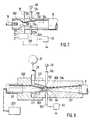
- the device according to the invention shown in FIG. 1contains an injector delivery device 2 with an injector channel 4 in the form of a Venturi tube.
- a delivery line 8 for supplying coating material in the form of powder to a spray device 10is connected to the downstream end of the injector channel 4. The latter sprays the powder 12 onto an object 14 to be coated.
- a conveying gas line 16opens axially into the upstream end of the injector channel 4, radially a control gas line 18, and also radially a powder line 20 from a powder container 21.
- the gas lines 16 and 18each contain a pressure regulator 22, 24 and / or a pressure measuring device 26, 28, and are connected to a compressed gas source 30.
- the pressure regulators 22, 24, pressure measuring devices 26, 28, and the pressure gas source 30are connected to an electronic evaluation device 42 via electrical lines 32, 34, 36, 38 and 40.
- the conveying line 8is provided with a radiation measuring device 44 which is connected to the electronic evaluation device 42 via electrical lines 46.
- the radiation measuring device 44contains a transmitter 48, which transmits beams 50 through the conveyor line 8, and a radiation receiver 52, which receives the beams 50 passing through the conveyor line 8.
- the rays 50are weakened as they pass through the conveyor line 8 both from the material of this conveyor line and from the powder flowing through it, depending on the amount of powder contained in the conveying gas, so that they are only weakened or only in the form of a part of them and thereby also arriving at the radiation receiver 52 in the form of an attenuation.
- the energy difference between the rays transmitted by the radiation transmitter 48 and the rays received by the receiver 52is a measure of the amount or density A of the powder contained in the gas, which flows through the delivery line 8.
- This dependence of the attenuation or reflection R of the rays 50 on the amount of powder contained in the gas stream and thus on the densityis shown in Fig. 2.
- the curve of FIG. 2runs slightly differently for each powder type. If desired, the corresponding dependency curves according to FIG. 2 can be stored for a plurality of powder types in a memory 54 of the evaluation device 42 and selected via a keyboard 56.
- the signals supplied via the lines 46therefore each correspond to a specific density value A, and these density values can be displayed by a display device 58 of the evaluation device 42.
- a further memory 60 of the evaluation device 42in the form of a curve diagram shown in FIG. 3, the dependence of the gas quantity supplied per time unit on the compressed gas source 30 is stored by the gas pressure P with which the gas from the compressed gas source reaches the upstream beginning of the injector channel 4 via the delivery line 16 and the control gas line 18.
- the electrical memory 60corresponds to a gas quantity sensor, which in the evaluation device 42 depends on the characteristic of the device, in this case depending on the gas pressure, a gas quantity value generated.
- the respective gas pressureis recognized by the electronic evaluation device by the control signal on lines 34 and 36 for pressure regulators 22 and 24, as well as by a pressure setting signal on line 40 to pressure source 30. If the electronic memory 60 fails, the electronic evaluation device 42, the pressure measurement signals of lines 32 and 38 from pressure measurement devices 28 and 26 as gas quantity values use, as these directly measured pressures correspond directly to the amount of gas delivered per unit of time.
- the electronic evaluation device 42is provided with the signals indicating a quantity ratio and thus the density and on the other hand the Signals determined on the clean gas side and corresponding to a certain amount of air per unit of time to disposal.
- the electronic evaluation device 42directly determines the actual value of the powder quantity conveyed per unit of time
- This quantity of powder conveyed per unit of timecan also be displayed in the display device 58.
- the electronic evaluation device 42preferably contains a microcomputer.
- the rays of the radiation measuring device 44can be visible or invisible light, in particular infrared light or ultraviolet light, but also laser rays, ⁇ -rays or electromagnetic rays. However, visible or invisible light is preferably used.
- the attenuation of the rays 50is measured by the powder content in the powder-air flow.
- the radiation measuring device 44can have a plurality of radiation transmitters 48, the beams 50 of which cross one another and pass through the delivery line 8 in a grid-like manner in different directions.
- the radiation receiver 52can contain a plurality of radiation sensors 53.
- uneven powder distributions in the delivery line 8can be determined and mean values can be formed to avoid incorrect measurement results.
- the conveying line 8can have a flattened line section and the radiation transmitter 48 and the radiation receiver 52 of the radiation measuring device can have an elongated shape corresponding to the flattened line section.
- the radiation transmitters 48 and radiation receivers 52are arranged on the same side of the delivery line 8.
- the radiation receivers 52do not receive the weakened rays passing through the delivery line 8, but rather the rays reflected by the powder in the delivery line 8.
- both the delivery line 8 and other elementswhich are possibly between the radiation transmitter and the radiation receiver on the one hand and the powder gas stream on the other hand, consist of a material which is easily permeable to the rays.
- This materialshould be much more permeable to the rays than the powder.
- When using light raysis therefore particularly suitable clear glass or clear plastic.
- FIG. 7shows in section an injector delivery device 102 with the two gas lines 16 and 18 and the powder line 20 of the powder container 21.
- the radiation measuring device 44is not arranged on the delivery line 8, but rather via light guides 124 and 126 in a narrowed channel section 128 of the injector channel 104, the weakening of the beams by the powder contained in the powder-gas stream measures and depending on this measurement result a signal corresponding to the powder content and thus the density value generated.
- the light guides 124 and 126do not extend through the entire wall 130 of the injector channel 104, so that they are each separated from the injector channel 104 by a thin wall section 132 and 134.
- the channel wall 130is made of translucent material so that the rays can pass through the injector channel 104, but the light guides 124 and 126 cannot be contaminated by powder.
- the ends 133 and 135 of the light guides 124 and 126are preferably close to or at the narrowest point 21 of the injector channel downstream of the powder line 20.
- the injector delivery device 202has an injector channel 204, which continuously widens downstream from a constriction 205.
- a plurality of circumferentially distributed channels 217arranged from one another, which are connected to gas source 30 via gas line 16.
- the powder line 20 of a powder container 221opens axially into the upstream end of the injector channel 204, upstream of the gas channels 217.
- the gas of the gas channels 217sucks powder out of the powder line 20 and drives it in the form of a powder-gas flow through the delivery line 8.
- Radially set back from the injector channel 204are the ends 133 of light guides 124 of a radiation transmitter 48, and the ends 135 of light guides 126 of a radiation receiver 52 of the radiation measuring device 44.
- the gas of the gas channels 217flows into the injector channel 204 at a very high speed, so that from this no powder particles can reach the ends 133 and 135 of the light guides 124 and 126 because the gas is between them and the powder particles of the injector channel.
- the ends 133 and 135 of the light guides 124 and 126face each other without interposing elements other than the powder and the gas.
- the ends 133 and 135are arranged in the mouth openings of the gas channels 217, but are placed on the radially outer channel edges so that the gas of the gas channels 217 can flow past them unhindered.
- the embodiment shown in FIG. 8has a particularly good delivery rate and also enables the measurement of very small changes in the powder content in the gas flow.
- the last-mentioned advantagearises from the fact that the gas swirls powder particularly strongly in the injector channel 204 and, as a result, a uniform powder division causes the ends 133 and 135 of the light guides 124 and 126 to direct the powder without a disturbing jacket wall of the delivery line 8 or the delivery device 202 -Gas flow opposite, and that the ends 133 and 135 can still not be contaminated by powder particles.
Landscapes
- Measuring Volume Flow (AREA)
- Nozzles (AREA)
- Investigating Materials By The Use Of Optical Means Adapted For Particular Applications (AREA)
- Application Of Or Painting With Fluid Materials (AREA)
Description
Translated fromGermanDie Erfindung betrifft eine Meß- und Regeleinrichtung für eine Pulversprühbeschichtungsanlage gemäß dem Oberbegriff von Anspruch 1.The invention relates to a measuring and control device for a powder spray coating system according to the preamble of claim 1.
Eine solche Meß- und Regeleinrichtung für eine Pulversprühbeschichtungsanlage ist aus der EP-A1 0 183 637 bekannt. Bei der bekannten Einrichtung sendet eine Strahlenquelle Strahlen durch einen Pulver-Gas-Strom und ein Strahlendetektor mißt den aus dem Pulver-Gas-Strom austretenden Strahlenanteil. Der im Pulver-Gas-Strom enthaltene Pulveranteil wird durch Multiplikation von zwei Faktoren und Division durch einen Strahlen-Dämpfungseffekt errechnet. Der eine Faktor besteht aus der Summe eines der Gasmenge entsprechenden Wertes und eines weiteren Wertes; der andere Faktor besteht aus dem Logarithmus eines Strahlenwertes, der durch Division gebildet wird.Such a measuring and control device for a powder spray coating system is known from EP-A1 0 183 637. In the known device, a radiation source sends rays through a powder-gas stream and a radiation detector measures the proportion of radiation emerging from the powder-gas stream. The proportion of powder contained in the powder-gas stream is calculated by multiplying two factors and dividing by a radiation damping effect. One factor consists of the sum of a value corresponding to the amount of gas and a further value; the other factor consists of the logarithm of a radiation value, which is formed by division.
Aus der DE-PS 28 49 295 ist eine Sprühbeschichtungsvorrichtung zum Beschichten von Gegenständen bekannt, welche in einer Fördergasleitung und in einer Steuergasleitung je einen Druckregler enthält. Die beiden Leitungen führen Gas zu einer Pulverfördereinrichtung, welche die Form eines Venturi-Injektors hat und Pulver aus einem Behälter in den Gasstrom saugt. Der Gasstrom fördert das Pulver zu einer Sprüheinrichtung. In der Fördergasleitung befindet sich ein Strömungsmeßgerät, dessen gemessener Istwert mit einem Sollwert verglichen wird. In Abhängigkeit vom Vergleichsergebnis regeln die Druckregler die Drücke in den beiden Gasleitungen.From DE-PS 28 49 295 a spray coating device for coating objects is known, each of which contains a pressure regulator in a conveying gas line and in a control gas line. The two lines lead gas to a powder delivery device, which is in the form of a venturi injector and sucks powder from a container into the gas stream. The gas flow conveys the powder to a spray device. There is a flow meter in the feed gas line, the measured actual value of which is compared with a target value. Depending on the comparison result, the pressure regulators regulate the pressures in the two gas lines.
Durch die Erfindung soll die Aufgabe gelöst werden, eine Einrichtung zu schaffen, mit welcher auf einfache Weise schnell, genau und störungsfrei die Pulvermenge ermittelt werden kann, welche pro Zeiteinheit gefördert wird. Ferner soll die Einrichtung so ausgebildet sein, daß die pro Zeiteinheit geförderte Pulvermenge genau angezeigt werden kann und/oder daß Steuer- oder Regelvorgänge automatisch schnell und genau durchgeführt werden können, um entweder eine gewünschte Pulvermenge pro Zeiteinheit einzustellen oder eine eingestellte Pulvermenge pro Zeiteinheit konstant zu halten.The object of the invention is to provide a device with which the amount of powder which is conveyed per unit of time can be determined in a simple, quick, accurate and trouble-free manner. Furthermore, the device should be designed so that the amount of powder conveyed per unit of time can be displayed precisely and / or that control or regulating processes can be carried out automatically quickly and accurately in order to either set a desired amount of powder per unit of time or to constantly set a set amount of powder per unit of time hold.
Diese Aufgabe wird gemäß der Erfindung durch die Kombination der Merkmale von Anspruch 1 gelöst.This object is achieved according to the invention by the combination of the features of claim 1.
Als Gas dient normalerweise Luft.Air is normally used as the gas.
Die Strahlen sind vorzugsweise sichtbares Licht oder unsichtbares Licht, insbesondere Infrarotlicht, Ultraviolettlicht oder Laserstrahlen. Möglich sind jedoch auch α-Strahlen und radioaktive Strahlen und andere Strahlen, welche von dem Pulver geschwächt oder reflektiert werden. Die Schwächung oder Reflexion der Strahlen hängt auch von der Art des Pulvers ab, welches beispielsweise Emaille oder Kunststoff sein kann oder zur Erzielung eines Metallic-Effektes zusätzlich auch Metall enthalten kann. Das Pulver kann auch ein Gewürz oder eine Gewürzmischung für Speisen sein, oder ein ähnliches fluidisierbares pulverförmiges bis granulatförmiges Material.The rays are preferably visible light or invisible light, in particular infrared light, ultraviolet light or laser beams. However, α-rays and radioactive rays and other rays which are weakened or reflected by the powder are also possible. The weakening or reflection of the rays also depends on the type of powder, which may be enamel or plastic, for example, or may also contain metal in order to achieve a metallic effect. The powder can also be a spice or a spice mixture for dishes, or a similar fluidizable powdery to granular material.
Durch die Erfindung wird die pro Zeiteinheit geförderte Pulvermenge direkt gemessen, indem einerseits im Pulver-Gas-Strom der Pulveranteil ermittelt wird, und andererseits auf der Reingasseite die Menge der pro Zeiteinheit zugeführten Gasmenge ermittelt wird, also bevor das Gas Pulver enthält. Aus den beiden Meßwerten wird die echte Pulvermenge automatisch errechnet, welche pro Zeiteinheit von dem Gas transportiert wird. Diese echte und direkte Meßung der geförderten Pulvermenge pro Zeiteinheit ist ein wesentlicher Vorteil gegenüber bekannten Einrichtungen, mit welchen nur Vergleichswerte, nicht jedoch die echten Werte an geförderter Pulvermenge festgestellt werden können.By means of the invention, the amount of powder delivered per unit of time is measured directly, on the one hand by determining the proportion of powder in the powder-gas stream, and on the other hand by determining the amount of gas supplied per unit of time on the clean gas side, ie before the gas contains powder. The real powder quantity, which is transported by the gas per unit of time, is automatically calculated from the two measured values. This real and direct measurement of the amount of powder conveyed per unit of time is a significant advantage over known devices with which can only be used to determine comparative values, but not the real values for the quantity of powder conveyed.
Ein weiterer Vorteil der Erfindung besteht darin, daß für jede Förderleitung und damit für jede Sprüheinrichtung getrennt die geförderte Pulvermenge pro Zeiteinheit festgestellt und geregelt werden kann, auch wenn mehrere Sprüheinrichtungen aus einem gemeinsamen Pulverbehälter Pulver erhalten.Another advantage of the invention is that the amount of powder conveyed per unit time can be determined and regulated separately for each delivery line and thus for each spray device, even if several spray devices receive powder from a common powder container.
Ein weiterer Vorteil der Erfindung besteht darin, daß der gemäß der Erfindung ermittelte Istwert an geförderter Pulvermenge pro Zeiteinheit weitgehend frei ist von störenden Faktoren.Another advantage of the invention is that the actual value of powder quantity conveyed per unit of time determined according to the invention is largely free of disruptive factors.
Die gemäß der Erfindung gemessene Schwächung oder Reflexion der Strahlen hängt davon ab, wieviel Pulver im Gas enthalten ist. Dadurch stellt der gemessene Wert der Schwächung oder Reflexion zunächst nur ein indirektes Maß der Dichte dar. Für eine bestimmte Pulversorte und eine bestimmte Querschnittsgröße des Pulver-Gas-Stromes entspricht jedoch dieser Wert gleichzeitig auch einer bestimmten Dichte, also einer bestimmten Menge von Pulver im Gas des Pulver-Gas-Stromes. Bei Verwendung einer anderen Pulversorte entspricht der gemessene Schwächungswert oder Reflexionswert einem anderen Dichtewert. Die Strahlenmeßeinrichtung oder die Auswerteinrichtung wird für jede Pulversorte entsprechend geeicht, so daß die gemessenen Schwächungswerte oder Reflexionswerte unmittelbar dem Dichtewert A entsprechen.The attenuation or reflection of the rays measured according to the invention depends on how much powder is contained in the gas. As a result, the measured value of the attenuation or reflection initially only represents an indirect measure of the density. However, for a specific type of powder and a specific cross-sectional size of the powder-gas flow, this value also corresponds to a specific density, that is to say a specific amount of powder in the gas of the powder-gas flow. If a different type of powder is used, the measured attenuation value or reflection value corresponds to a different density value. The radiation measuring device or the evaluation device is calibrated accordingly for each powder type, so that the measured attenuation values or reflection values correspond directly to the density value A.
Im Rahmen der Erfindung kann die Menge von Gas, welche in dem Pulver-Gas-Strom enthalten ist und zur Förderung des Pulvers dient, auf verschiedene Weise ermittelt werden:
In einer oder mehreren Gas-Leitungen auf der Reingasseite der Fördereinrichtung ist ein Druckmeßgerät vorgesehen, welches den Gasdruck und damit indirekt die Gasmenge mißt, da die geförderte Gasmenge vom Gasdruck abhängig ist. Mit Gasdruck-Meßsignalen kann über eine Druck-Mengen-Kennlinie automatisch die Gasmenge ermittelt werden. Die Kennlinie ist elektronisch, vorzugsweise in der Auswerteinrichtung, gespeichert.In the context of the invention, the amount of gas which is contained in the powder-gas stream and is used to convey the powder can be determined in various ways:
A pressure measuring device is provided in one or more gas lines on the clean gas side of the delivery device, which measures the gas pressure and thus indirectly the amount of gas, since the amount of gas delivered is dependent on the gas pressure. With gas pressure measurement signals, the amount of gas can be determined automatically via a pressure-quantity characteristic. The characteristic curve is stored electronically, preferably in the evaluation device.
In der oder den Gas-Leitungen zur Zufuhr des Gases zu einer pneumatischen Fördereinrichtung kann sich ein Druckregler zur Einstellung des Gasdruckes und damit zur Einstellung der pro Zeiteinheit geförderten Gasmenge befinden. Zur Einstellung des Druckreglers dienende Signale sind ein Maß für den eingestellten Gasdruck und damit auch für die pro Zeiteinheit geförderte Gasmenge. Deshalb können diese Signale, anstelle der Signale eines zusätzlichen Mengenmeßgerätes oder Druckmeßgerätes, zur Ermittlung der pro Zeiteinheit geförderten Gasmenge verwendet werden. In diesem Fall ist, ähnlich wie bei Verwendung eines Druckmeßgerätes, eine Druckeinstellsignal-Gasmenge-Kennlinie in einem elektronischen Speicher gespeichert. Der Speicher kann in die Auswerteinrichtung integriert sein. Die Auswerteinrichtung dient einerseits zur Druckregelung und andererseits zur Ermittlung der pro Zeiteinheit geförderten Gasmenge, also des Gasmengenwertes B. Der Gasmengen-Meßwertgeber ist in diesem Falle der elektronische Speicher.A pressure regulator for adjusting the gas pressure and thus for adjusting the amount of gas delivered per unit of time can be located in the gas line or lines for supplying the gas to a pneumatic conveying device. Signals used to set the pressure regulator are a measure of the gas pressure set and thus also of the amount of gas delivered per unit of time. Therefore, these signals can be used to determine the amount of gas delivered per unit of time, instead of the signals from an additional quantity measuring device or pressure measuring device. In this case, similar to the use of a pressure measuring device, a pressure setting signal-gas quantity characteristic curve is stored in an electronic memory. The memory can be integrated in the evaluation device. The evaluation device serves on the one hand to regulate the pressure and on the other hand to determine the amount of gas delivered per unit of time, that is to say the gas amount value B. In this case, the gas amount sensor is the electronic memory.
Vorzugsweise sind gemäß der Erfindung in der elektronischen Auswerteinrichtung für verschiedene Pulversorten auch die Dichtewerte A gespeichert, welche einem bestimmten Schwächungswert oder Reflexionswert der Strahlen entsprechen. Abweichend hiervon kann gemäß einer anderen Ausführungsform diese Abhängigkeit auch unmittelbar in der Strahlenmeßeinrichtung gespeichert sein.According to the invention, the density values A, which correspond to a specific attenuation value or reflection value of the beams, are preferably also stored in the electronic evaluation device for different types of powder. Deviating from this, according to another embodiment, this dependency can also be stored directly in the radiation measuring device.
Gemäß der Erfindung weist die Strahlenmeßeinrichtung mindestens einen Strahlensender und mindestens einen Strahlenempfänger auf, welcher im Strahlenweg der vom Strahlensender in den Pulver-Gas-Strom gesendeten und von dessen Pulver geschwächten oder reflektierten Strahlen angeordnet ist.According to the invention, the radiation measuring device has at least one radiation transmitter and at least one radiation receiver, which is arranged in the radiation path of the rays transmitted from the radiation transmitter into the powder-gas stream and weakened or reflected by the powder thereof.
In bevorzugter Ausführungsform der Erfindung ist eine Vielzahl von Strahlenempfängern vorgesehen, die auf verschiedene Querschnittsbereiche des Pulver-Gas-Stromes gerichtet sind und für jeden Querschnittsbereich Dichtewert-Signale erzeugen, die zusammen einen Durchschnitts-Dichtewert ergeben. Dadurch werden falsche Ergebnisse vermieden, die entstehen können, wenn das Pulver über den Querschnitt des Pulver-Gas-Stromes ungleich verteilt ist.In a preferred embodiment of the invention, a multiplicity of radiation receivers are provided which are directed at different cross-sectional areas of the powder-gas stream and generate density value signals for each cross-sectional area, which together give an average density value. This avoids incorrect results that can arise if the powder is distributed unevenly across the cross-section of the powder-gas flow.
Gemäß einer bevorzugten Ausführungsform der Erfindung erstreckt sich der Strahlenweg zwischen dem Strahlensender und dem Strahlenempfänger quer durch einen Injektorkanal einer Injektor-Fördereinrichtung, in welchen das Gas Pulver aus einer Pulver-Zuleitung ansaugt und den Pulver-Gas-Strom bildet. In der Injektor-Fördereinrichtung herrschen stets gleichbleibende Strömungsbedingungen und, infolge der Verwirbelung des Pulvers durch das Gas, eine im wesentlichen homogene Pulververteilung.According to a preferred embodiment of the invention, the radiation path between the radiation transmitter and the radiation receiver extends across an injector channel of an injector delivery device, in which the gas sucks powder from a powder feed line and forms the powder-gas flow. The flow conditions in the injector delivery device are always constant and, due to the swirling of the powder by the gas, there is an essentially homogeneous powder distribution.
Gemäß der Erfindung sind der Strahlensender und der Strahlenempfänger durch das Gas für den Pulver-Gas-Strom vom Pulver abgeschirmt. Dadurch wird vermieden, daß sich Pulver an dem Strahlensender und/ oder an dem Strahlenempfänger festsetzen kann. Im Injektorkanal erreicht das Gas sehr hohe Geschwindigkeiten, so daß mit Sicherheit kein Pulver durch den Gasstrom zu dem Strahlensender oder Strahlenempfänger gelangen kann, wenn diese im Gasstrom oder unmittelbar neben ihm auf seiner vom Injektorkanal abgewandten Seite enden.According to the invention, the radiation transmitter and the radiation receiver are through the gas for the powder-gas flow shielded from powder. This prevents powder from adhering to the radiation transmitter and / or the radiation receiver. The gas reaches very high speeds in the injector channel, so that certainly no powder can reach the radiation transmitter or radiation receiver through the gas stream if these end in the gas stream or directly next to it on its side facing away from the injector channel.
Gemäß einer anderen Ausführungsform der Erfindung enden der Strahlensender und der Strahlenempfänger in einer Mantelwand des Injektorkanals, und sie sind über ein strahlendurchlässiges Material vom Injektorkanal getrennt. Hiermit wird eine Verschmutzung des Strahlensenders und des Strahlenempfängers durch Pulver vermieden.According to another embodiment of the invention, the radiation transmitter and the radiation receiver end in a jacket wall of the injector channel, and they are separated from the injector channel by a radiation-permeable material. This prevents contamination of the radiation transmitter and the radiation receiver by powder.
Gemäß einer besonderen Ausführungsform der Erfindung ist vorgesehen, daß der Injektorkanal in Strömungsrichtung verengt und dann wieder erweitert ist, daß die Pulver-Zuleitung stromaufwärts der engsten Kanalstelle axial in den Injektorkanal mündet, und daß mindestens eine Leitung für das Gas in der Mantelwandfläche des Injektorkanals im Bereich seines verengten Kanalabschnittes ausmündet. Diese Ausführungsform ermöglicht besonders genaue Dichtemeßwerte, weil im Injektorkanal eine gleichbleibende, im wesentlichen homogene Pulververteilung im Pulver-Gas-Strom herrscht. Außerdem ist es bei dieser Art besonders einfach, Strahlensender und Strahlenempfänger so anzubringen, daß sie weder durch Pulver verschmutzen, noch durch äußere Störeinflüsse beeinträchtigt werden können.According to a special embodiment of the invention, it is provided that the injector channel is narrowed in the flow direction and then expanded again, that the powder feed line opens axially into the injector channel upstream of the narrowest channel point, and that at least one line for the gas in the jacket wall surface of the injector channel in Area of its narrowed channel section opens out. This embodiment enables particularly precise measured density values because there is a constant, essentially homogeneous powder distribution in the powder-gas stream in the injector channel. In addition, with this type it is particularly easy to attach the radiation transmitter and the radiation receiver in such a way that they can neither be contaminated by powder, nor can they be impaired by external interference.
Nach einer weiteren Ausführungsform der Erfindung dient ein den Druck des Gases erzeugendes oder regelndes Gerät gleichzeitig auch als Gasmengen-Meßwertgeber, indem ein Druckeinstellsignal für dieses Gerät von der Auswerteinrichtung als Gasmengenwert
verwendet wird.According to a further embodiment of the invention, a device which generates or regulates the pressure of the gas also simultaneously serves as a gas quantity measuring value transmitter, in that a pressure setting signal for this device from the evaluation device serves as a gas quantity value
is used.
In der Erfindung ist der Gasmengen-Meßwertgeber ein Datenspeicher, in welchem die Abhängigkeit der pro Zeiteinheit strömenden Gasmenge des Pulver-Gas-Stromes von einem variablen Charakteristikwert der Einrichtung wie ein Kurvendiagramm gespeichert ist, und daß die Auswerteinrichtung in Abhängigkeit von dem jeweiligen Charakteristikwert aus dem gespeicherten Kurvendiagramm die Gasmenge B ermittelt. Diese charakteristikwerte sind der Gasdruck, Öffnungsquerschnitt der Strömungsmittelleitungen und die Länge der Strömungsmittelleitungen.In the invention, the gas quantity sensor is a data memory in which the dependence of the gas quantity of the powder-gas stream flowing per unit time on a variable characteristic value of the device is stored like a curve diagram, and that the evaluation device is dependent on the respective characteristic value from the stored curve diagram determines the amount of gas B. These characteristic values are the gas pressure, opening cross-section of the fluid lines and the length of the fluid lines.
Vorzugsweise dient gemäß der Erfindung als Charakteristikwert der Einrichtung der jeweilige Gasdruck, der an einer Stelle stromaufwärts des Pulver-Gas-Stromes im Gas gemessen oder eingestellt wird, welches dem Pulver-Gas-Strom zugeführt wird. Da der Gasdruck direkt die Gasmenge bestimmt, ist dies eine einfache Maßnahme, durch welche die Auswerteinrichtung die pro Zeiteinheit zugeführte Gasmenge bestimmen kann.According to the invention, the respective gas pressure which is measured or set at a point upstream of the powder-gas stream in the gas which is fed to the powder-gas stream preferably serves as the characteristic value of the device. Since the gas pressure directly determines the amount of gas, this is a simple measure by which the evaluation device can determine the amount of gas supplied per unit of time.
Vorzugsweise enthält die Auswerteinrichtung zur Ausführung ihrer Funktionen einen Mikrocomputer.The evaluation device preferably contains a microcomputer for performing its functions.
Die Erfindung wird nunmehr mit Bezug auf die Zeichnungen beschrieben, in welchen mehrere Ausführungsformen der Erfindung als Beispiele dargestellt sind. Im Einzelnen zeigen
- Fig. 1
- eine schematische Darstellung einer Einrichtung nach der Erfindung, unmaßstäblich,
- Fig. 2
- ein mögliches Kurvendiagramm, in welchem die Dichte

vom Wert R der Schwächung oder Reflexion der Strahlen unmaßstäblich dargestellt ist, - Fig. 3
- ein Kurvendiagramm, in welchem die Abhängigkeit des Gasmengenwertes

- Fig. 4
- eine abgewandelte Ausführungsform im Querschnitt der in Fig. 1 dargestellten Einrichtung,
- Fig. 5
- eine weiter abgewandelte Ausführungsform im Querschnitt der Einrichtung nach Fig. 1,
- Fig. 6
- eine nochmals abgewandelte Auführungsform im Querschnitt der Einrichtung nach Fig. 1,
- Fig. 7
- eine gegenüber Fig. 1 abgewandelte Ausführungsform einer Injektor-Fördereinrichtung im Längsschnitt,
- Fig. 8
- eine weiter abgewandelte Ausführungsform einer Injektor-Fördereinrichtung der Einrichtung von Fig. 1.


- Fig. 1
- 1 shows a schematic representation of a device according to the invention, not to scale,
- Fig. 2
- a possible curve diagram in which the density
is shown to scale of the attenuation or reflection of the rays, - Fig. 3
- a curve diagram in which the dependence of the gas quantity value
- Fig. 4
- 2 shows a modified embodiment in cross section of the device shown in FIG. 1,
- Fig. 5
- 4 shows a further modified embodiment in cross section of the device according to FIG. 1,
- Fig. 6
- 2 shows a further modified embodiment in cross section of the device according to FIG. 1,
- Fig. 7
- 2 shows an embodiment of an injector delivery device modified in longitudinal section,
- Fig. 8
- 4 shows a further modified embodiment of an injector delivery device of the device from FIG. 1.
Die in Fig. 1 dargestellte Einrichtung nach der Erfindung enthält eine Injektor-Fördereinrichtung 2 mit einem Injektorkanal 4 in Form eines Venturirohres. An das stromabwärtige Ende des Injektorkanals 4 ist eine Förderleitung 8 zur Zufuhr von Beschichtungsmaterial in Form von Pulver zu einer Sprüheinrichtung 10 angeschlossen. Letztere sprüht das Pulver 12 auf einen zu beschichtenden Gegenstand 14. In das stromaufwärtige Ende des Injektorkanals 4 mündet axial eine Fördergasleitung 16, radial eine Steuergasleitung 18, und ebenfalls radial eine Pulverleitung 20 von einem Pulverbehälter 21 . Die Gasleitungen 16 und 18 enthalten jeweils einen Druckregler 22, 24 und/oder ein Druckmeßgerät 26, 28, und sind an eine Druckgasquelle 30 angeschlossen. Die Druckregler 22, 24, Druckmeßgeräte 26, 28, und die Druckgasquelle 30 sind über elektrische Leitungen 32, 34, 36, 38 und 40 an eine elektronische Auswerteinrichtung 42 angeschlossen. Die Förderleitung 8 ist mit einer Strahlenmeßeinrichtung 44 versehen, welche über elektrische Leitungen 46 an die elektronische Auswerteinrichtung 42 angeschlossen ist. Die Strahlenmeßeinrichtung 44 enthält einen Sender 48, welcher Strahlen 50 durch die Förderleitung 8 sendet, und einen Strahlenempfänger 52, welcher die durch die Förderleitung 8 hindurch gehenden Strahlen 50 empfängt. Die Strahlen 50 werden beim Durchgang durch die Förderleitung 8 sowohl vom Material dieser Förderleitung als auch von dem durch sie hindurchströmenden Pulver, in Abhängigkeit von der im fördernden Gas enthaltenen Pulvermenge, geschwächt, so daß sie nur geschwächt oder nur in Form eines Teiles von ihnen und dadurch in Form ebenfalls einer Schwächung, am Strahlenempfänger 52 ankommen. Der Energieunterschied zwischen den vom Strahlensender 48 gesendeten Strahlen und den vom Empfänger 52 empfangenen Strahlen ist ein Maß für die Menge oder Dichte A des im Gas enthaltenen Pulvers, welches durch die Förderleitung 8 strömt. Diese Abhängigkeit der Schwächung oder Reflexion R der Strahlen 50 von der Menge des im Gasstrom enthaltenen Pulvers und damit von der Dichte
ist in Fig. 2 dargestellt. Für jede Pulversorte verläuft die Kurve von Fig. 2 geringfügig anders. Gewünschtenfalls können für mehrere Pulversorten die entsprechenden Abhängigkeitskurven gemäß Fig. 2 in einem Speicher 54 der Auswerteinrichtung 42 gespeichert sein und über eine Tastatur 56 gewählt werden. Die über die Leitungen 46 gelieferten Signale entsprechen also jeweils einem bestimmten Dichtewert A, und diese Dichtewerte können durch ein Anzeigegerät 58 der Auswerteinrichtung 42 angezeigt werden.The device according to the invention shown in FIG. 1 contains an injector delivery device 2 with an injector channel 4 in the form of a Venturi tube. A
is shown in Fig. 2. The curve of FIG. 2 runs slightly differently for each powder type. If desired, the corresponding dependency curves according to FIG. 2 can be stored for a plurality of powder types in a
In einem weiteren Speicher 60 der Auswerteinrichtung 42 ist in Form eines in Fig. 3 dargestellten Kurvendiagrammes die Abhängigkeit der pro Zeiteinheit von der Druckgasquelle 30 gelieferten Gasmenge
vom Gasdruck P gespeichert, mit welchem das Gas der Druckgasquelle über die Förderleitung 16 und die Steuergasleitung 18 in den stromaufwärtigen Anfang des Injektorkanals 4 gelangt. Der elektrische Speicher 60 entspricht einem Gasmengen-Meßwertgeber, welcher in der Auswerteinrichtung 42 in Abhängigkeit von der Charakteristik der Einrichtung, in diesem Falle in Abhängigkeit vom Gasdruck, einen Gasmengenwert
erzeugt. Der jeweilige Gasdruck wird von der elektronischen Auswerteinrichtung durch das Stellsignal auf den Leitungen 34 und 36 für die Druckregler 22 und 24 erkannt, ebenso durch ein Druckeinstellsignal auf der Leitung 40 zur Druckquelle 30. Falls der elektronische Speicher 60 ausfällt, kann die elektronische Auswerteinrichtung 42 die Druckmeßsignale der Leitungen 32 und 38 von den Druckmeßgeräten 28 und 26 als Gasmengenwerte
verwenden, da diese direkt gemessenen Drücke direkt der pro Zeiteinheit geförderten Menge Gas entsprechen.In a
stored by the gas pressure P with which the gas from the compressed gas source reaches the upstream beginning of the injector channel 4 via the
generated. The respective gas pressure is recognized by the electronic evaluation device by the control signal on
use, as these directly measured pressures correspond directly to the amount of gas delivered per unit of time.
Somit stehen der elektronischen Auswerteinrichtung 42 einerseits die ein Mengenverhältnis und damit die Dichte angebenden Signale
und andererseits die
auf der Reingasseite ermittelten, einer bestimmten Luftmenge pro Zeiteinheit entsprechenden Signale
zur Verfügung. Durch elektronische Multiplikation der beiden Werte A und B, oder durch eine der Multiplikation entsprechende Verknüpfung der Signalwerte A und B, ermittelt die elektronische Auswerteinrichtung 42 unmittelbar den Istwert der pro Zeiteinheit geförderten Pulvermenge
and on the other hand the
Signals determined on the clean gas side and corresponding to a certain amount of air per unit of time
to disposal. By electronically multiplying the two values A and B, or by combining the signal values A and B in accordance with the multiplication, the
Diese pro Zeiteinheit geförderte Pulvermenge kann ebenfalls im Anzeigegerät 58 angezeigt werden.This quantity of powder conveyed per unit of time can also be displayed in the
Die elektronische Auswerteinrichtung 42 enthält zur Ausübung ihrer Funktionen vorzugsweise einen Mikrocomputer.To carry out its functions, the
Die Strahlen der Strahlenmeßeinrichtung 44 können sichtbares oder unsichtbares Licht, insbesondere Infrarotlicht oder Ultraviolettlicht sein, jedoch auch Laserstrahlen, α-Strahlen oder elektromagnetische Strahlen. Vorzugsweise wird jedoch sichtbares oder unsichtbares Licht verwendet.The rays of the
Bei der Ausführungsform nach Fig. 1 wird die Schwächung der Strahlen 50 durch den Pulvergehalt in der Pulver-Luft-Strömung gemessen. Wie Fig. 4 zeigt, kann die Strahlenmeßeinrichtung 44 mehrere Strahlensender 48 haben, deren Strahlen 50 einander kreuzen und in verschiedenen Richtungen rasterförmig durch die Förderleitung 8 gehen. Der Strahlenempfänger 52 kann eine Vielzahl von Strahlensensoren 53 enthalten. Dadurch können ungleichmäßige Pulververteilungen in der Förderleitung 8 festgestellt und zur Vermeidung von falschen Meßergebnissen Mittelwerte gebildet werden. Gemäß der weiteren Ausführungsform nach Fig. 5 können die Förderleitung 8 einen abgeflachten Leitungsabschnitt und der Strahlensender 48 sowie der Strahlenempfänger 52 der Strahlenmeßeinrichtung eine dem abgeflachten Leitungsabschnitt entsprechende längliche Form haben.In the embodiment according to FIG. 1, the attenuation of the
Bei der in Fig. 6 dargestellten Ausführungsform eines Strahlenmeßgerätes 44 sind die Strahlensender 48 und Strahlenempfänger 52 auf der gleichen Seite der Förderleitung 8 angeordnet. Dabei empfangen die Strahlenempfänger 52 nicht die durch die Förderleitung 8 hindurchgehenden geschwächten Strahlen, sondern die vom Pulver in der Förderleitung 8 reflektierten Strahlen.In the embodiment of a
Für alle Ausführungsformen ist es selbstverständlich erforderlich, daß sowohl die Förderleitung 8 als auch andere Elemente, die sich gegebenenfalls zwischen Strahlensender und Strahlenempfänger einerseits und dem Pulver-Gas-Strom andererseites befinden, aus einem für die Strahlen leicht durchlässigen Material bestehen. Dieses Material sollte wesentlich leichter durchlässig sein für die Strahlen, als das Pulver. Bei Verwendung von Lichtstrahlen eignet sich deshalb insbesondere durchsichtiges Glas oder durchsichtiger Kunststoff.For all embodiments, it is of course necessary that both the
Die in Fig. 7 dargestellte weitere Ausführungsform der Erfindung zeigt im Schnitt eine Injektor-Fördereinrichtung 102 mit den beiden Gasleitungen 16 und 18 und der Pulverleitung 20 des Pulverbehälters 21 . Der wesentliche Unterschied zu Fig. 1 besteht darin, daß die Strahlenmeßeinrichtung 44 nicht an der Förderleitung 8 angeordnet ist, sondern über Lichtleiter 124 und 126 in einem verengten Kanalabschnitt 128 des Injektorkanals 104 die Schwächung der Strahlen durch das im Pulver-Gas-Strom enthaltene Pulver mißt und in Abhängigkeit von diesem Meßergebnis ein Signal entsprechend dem Pulveranteil und damit dem Dichtewert
erzeugt. Die Lichtleiter 124 und 126 erstrecken sich nicht durch die gesamte Wand 130 des Injektorkanals 104, so daß sie jeweils durch einen dünnen Wandabschnitt 132 und 134 vom Injektorkanal 104 getrennt sind. Die Kanalwand 130 besteht aus lichtdurchlässigem Material, so daß die Strahlen durch den Injektorkanal 104 hindurchgehen können, jedoch die Lichtleiter 124 und 126 nicht von Pulver verschmutzt werden können. Die Enden 133 und 135 der Lichtleiter 124 und 126 befinden sich vorzugsweise nahe bei oder an der engsten Stelle 21 des Injektorkanals stromabwärts der Pulverleitung 20.The further embodiment of the invention shown in FIG. 7 shows in section an
generated. The light guides 124 and 126 do not extend through the
Bei einer weiteren Ausführungsform nach der Erfindung, welche in Fig. 8 dargestellt ist, hat die Injektor-Fördereinrichtung 202 einen Injektorkanal 204, welcher sich von einer Engstelle 205 stromabwärts kontinuierlich erweitert. In der Mantelwandfläche 209 des erweiterten Kanalabschnittes 207 münden, unter spitzem Winkel zur Kanalachse, eine Vielzahl von in Umfangsrichtung verteilt voneinander angeordneten Kanälen 217, welche über die Gasleitung 16 an die Gasquelle 30 angeschlossen sind. In das stromaufwärtige Ende des Injektorkanals 204 mündet, stromaufwärts der Gaskanäle 217, axial die Pulverleitung 20 eines Pulverbehälters 221. Das Gas der Gaskanäle 217 saugt aus der Pulverleitung 20 Pulver an und treibt es in Form eines Pulver-Gas-Stromes durch die Förderleitung 8. Radial zurückgesetzt vom Injektorkanal 204 befinden sich die Enden 133 von Lichtleitern 124 eines Strahlensenders 48, und die Enden 135 von Lichtleitern 126 eines Strahlenempfängers 52 der Strahlenmeßeinrichtung 44. Das Gas der Gaskanäle 217 strömt mit sehr hoher Geschwindigkeit in den Injektorkanal 204, so daß von diesem keine Pulverteilchen zu den Enden 133 und 135 der Lichtleiter 124 und 126 gelangen können, da sich das Gas zwischen ihnen und den Pulverteilchen des Injektorkanals befindet. Zusätzlich besteht der Vorteil, daß die Enden 133 und 135 der Lichtleiter 124 und 126 einander gegenüber liegen, ohne daß sich dazwischen andere Elemente außer dem Pulver und dem Gas befinden. Gemäß Fig. 8 sind die Enden 133 und 135 in den Mündungsöffnungen der Gaskanäle 217 angeordnet, dabei jedoch an die radial äußeren Kanalränder gelegt, damit das Gas der Gaskanäle 217 ungehindert an ihnen vorbeiströmen kann. Die in Fig. 8 gezeigte Ausführungsform hat eine besonders gute Förderleistung und ermöglicht außerdem die Messung von sehr kleinen Veränderungen des Pulveranteils im Gasstrom. Der letztgenannte Vorteil ergibt sich dadurch, daß das Gas Pulver im Injektorkanal 204 besonders stark verwirbelt und dadurch eine gleichmäßige Pulverteilung bewirkt, daß die Enden 133 und 135 der Lichtleiter 124 und 126, ohne eine störende Mantelwand der Förderleitung 8 oder der Fördereinrichtung 202 direkt dem Pulver-Gas-Strom gegenüberliegen, und daß die Enden 133 und 135 trotzdem nicht durch Pulverteilchen verschmutzt werden können.In a further embodiment according to the invention, which is shown in FIG. 8, the
Claims (8)
- A metering and regulating device for a powder spray coating installation for metering and regulating the powder flow per unit of time, which is supplied to a spray device (10) for the spray coating of objects (14) by a stream of gas; havinga) a ray metering device (44), which directs rays for contact-free metering towards the powder-gas flow, and produces an electrical signal, hereinafter called the density value signal, the value of which depends on the weakening or reflection of these rays at the powder-gas flow;b) a device (60, 22, 24, 26, 28) for producing an electrical signal, hereinafter called the gas flow signal, in dependence on the gas flow supplied per unit of time, before this gas receives powder;c) an electronic evaluation device (42), which from the density value signal and the gas flow signal calculates the powder flow in the powder-gas stream supplied per unit of time in the form of a multiplication product and generates a signal, hereinafter called the powder flow signal, the value of which is dependent on the calculated multiplication product;characterised in that the device (60, 22, 24, 26, 28) for producing the gas flow signal comprises a memory (60), in which a curve diagram is stored, which represents the dependence of the gas flow of the powder-gas stream flowing per unit of time on the gas pressure, on the opening cross section of the flow medium lines and/or on the length of the flow medium lines (16, 18, 20, 8),
and in that the evaluation device (42) is constructed so that it produces as a function of the respective characteristic value from the stored curve diagram the gas flow signal corresponding thereto;
in that the electronic evaluation device (42) contains means and a microcomputer, with the help of which it acceptsa1) the density value signal as b1) the gas flow signal as
 c1) the powder flow signalby forming the multiplication product "A.B" from the density value A and the gas flow value B.
- A device according to Claim 1,
characterised in that the ray metering device (44) comprises at least one ray transmitter (48) and at least one ray receiver (52), which is disposed in the ray path (50) of the ray transmitted by the ray transmitter into the powder-gas stream and weakened or reflected by its powder. - A device according to Claim 2,
characterised in that a plurality of ray receivers (52, 53) is provided, which are directed onto various cross-sectional regions of the powder-gas stream and for each cross-sectional region generate density value signals which together produce a density value A. - A device according to Claim 2 or 3,
characterised in that the ray path (50) between the ray transmitter (48) and the ray receiver (52) extends transversally through an injector duct (104, 204) of an injector conveying device (102, 202), in which the gas sucks powder out of a powder supply line and forms the powder-gas stream (Fig. 7, 8). - A device according to Claim 4,
characterised in that the ray transmitter (48) and the ray receiver (52) are separated only from the powder of the powder-gas stream by gas, which flows to the powder-gas stream, (Fig.8). - A device according to Claim 4,
characterised in that the ray transmitter (48) and the ray receiver (52) end in a casing wall (130) of the injector duct and are separated from the injector duct (104) via radiolucent material (132, 134). - A device according to one of Claims 4 to 6,
characterised in that the injector duct (204) becomes narrower in the direction of flow and then wider again,
in that the powder supply line (20) axially opens into the injector duct (204) upstream from the narrowest duct location (205),
and in that at least one line (217) of the gas for the powder-gas stream opens into the narrowed and again widened duct section of the injector duct (204). - A device according to one of Claims 1 to 7,
characterized in that a device generating (30) or regulating (22, 24) the pressure of the gas is also simultaneously used as a gas flow sensor by a set signal for this device being used by the evaluation device (42) as the gas flow value


Applications Claiming Priority (2)
| Application Number | Priority Date | Filing Date | Title |
|---|---|---|---|
| DE3721875 | 1987-07-02 | ||
| DE19873721875DE3721875A1 (en) | 1987-07-02 | 1987-07-02 | METHOD AND DEVICE FOR A POWDER SPRAY COATING SYSTEM |
Publications (3)
| Publication Number | Publication Date |
|---|---|
| EP0297309A2 EP0297309A2 (en) | 1989-01-04 |
| EP0297309A3 EP0297309A3 (en) | 1989-10-18 |
| EP0297309B1true EP0297309B1 (en) | 1993-12-22 |
Family
ID=6330768
Family Applications (1)
| Application Number | Title | Priority Date | Filing Date |
|---|---|---|---|
| EP88108891AExpired - LifetimeEP0297309B1 (en) | 1987-07-02 | 1988-06-03 | Process and device for metering and regulating the powder flow in a powder spray coating installation |
Country Status (4)
| Country | Link |
|---|---|
| US (1) | US4941778A (en) |
| EP (1) | EP0297309B1 (en) |
| JP (1) | JPH0661498B2 (en) |
| DE (2) | DE3721875A1 (en) |
Cited By (6)
| Publication number | Priority date | Publication date | Assignee | Title |
|---|---|---|---|---|
| EP0412289A3 (en)* | 1989-08-11 | 1991-10-02 | Ransburg-Gema Ag | Electrostatic spray device |
| US5215253A (en)* | 1990-08-30 | 1993-06-01 | Nordson Corporation | Method and apparatus for forming and dispersing single and multiple phase coating material containing fluid diluent |
| DE4440417A1 (en)* | 1994-11-11 | 1996-05-15 | Bayerische Motoren Werke Ag | Measuring device for determining a powder content |
| US5864239A (en)* | 1996-12-03 | 1999-01-26 | Wagner International | Apparatus for measuring a powder mass flow |
| WO2000053334A1 (en) | 1999-03-11 | 2000-09-14 | Itw Gema Ag | Powder coating device |
| CN103447187A (en)* | 2012-05-30 | 2013-12-18 | 上海蓝蔚科技发展有限公司 | Calculation method for controlling speed of spraying machine according to catalyst loading |
Families Citing this family (52)
| Publication number | Priority date | Publication date | Assignee | Title |
|---|---|---|---|---|
| DE3822835A1 (en)* | 1988-07-06 | 1990-03-08 | Josef Schucker | Process and arrangement for coating workpiece surfaces |
| IL93251A0 (en)* | 1989-02-06 | 1990-11-29 | Pfizer Hospital Prod | Method and apparatus for improvement of bone healing |
| DE4033470C1 (en)* | 1990-10-20 | 1992-04-02 | Grafotec Kotterer Gmbh, 8901 Diedorf, De | |
| FR2680416B1 (en)* | 1991-08-12 | 1995-06-30 | Sames Sa | FLUIDIZED POWDER FLOW MEASURING METHOD AND FLOW MEASURING DEVICE USING SUCH A METHOD. |
| DE4201665C2 (en)* | 1992-01-22 | 1993-10-28 | Wagner International Ag Altsta | Powder injector |
| DE4319726A1 (en)* | 1993-06-15 | 1994-12-22 | Gema Volstatic Ag | Powder conveyor |
| JP2728847B2 (en)* | 1993-07-23 | 1998-03-18 | 日本パーカライジング株式会社 | Powder flow rate measuring method and apparatus |
| DE4325044C2 (en)* | 1993-07-26 | 2002-07-18 | Itw Gema Ag | Powder conveying device, in particular for coating powder |
| DE4406046C2 (en)* | 1994-02-24 | 1997-11-20 | Wagner Int | Device and method for measuring a powder mass flow |
| DE4419987A1 (en)* | 1994-06-08 | 1996-02-29 | Gema Volstatic Ag | Injector conveyor for the pneumatic conveying of powder |
| DE4426264A1 (en)* | 1994-07-25 | 1996-02-01 | Siemens Ag | Method and device for producing and metering a powder aerosol |
| US5561527A (en)* | 1995-03-13 | 1996-10-01 | Hughes Aircraft Company | Optical sensing apparatus for CO2 jet spray devices |
| DE19514326C2 (en)* | 1995-04-18 | 1998-04-02 | Wolfgang Peltzer | Device for blowing in particulate insulating materials |
| DE19548607A1 (en)* | 1995-12-23 | 1997-06-26 | Gema Volstatic Ag | Powder spray coater |
| DE19608432A1 (en)* | 1996-03-05 | 1997-09-18 | Medicoat Ag | Device for controlling the metered feeding of powder to a powder processing unit |
| EP0823286B1 (en)* | 1996-08-07 | 2003-01-02 | Elpatronic Ag | Injector arrangement for transporting particulate materials |
| DE19717353A1 (en)* | 1997-04-24 | 1998-11-05 | Wagner Int | Powder coating system with several coating units arranged vertically |
| DE19808765A1 (en)* | 1998-03-02 | 1999-09-16 | Wagner Int | Powder coating system and method for feeding and mixing powder in a coating system |
| DE19824802A1 (en)* | 1998-06-03 | 1999-12-09 | Itw Gema Ag | Powder feed injector |
| JP4045022B2 (en)* | 1998-07-29 | 2008-02-13 | 株式会社カワタ | Powder measuring device |
| DE19847258B4 (en)* | 1998-10-02 | 2008-09-04 | Thyssenkrupp Anlagenservice Gmbh | Method and apparatus for condition detection of coating compositions in the electrostatic coating of objects |
| DE19949659C2 (en)* | 1999-10-14 | 2002-06-13 | Wagner Internat Ag Altstaetten | Method and device for determining a powder quantity or powder quantity change in a container |
| US6668663B2 (en)* | 2000-12-27 | 2003-12-30 | Analytical Engineering, Inc. | Method and apparatus to determine flow rate with the introduction of ambient air |
| DE10111383B4 (en)* | 2001-03-09 | 2006-02-09 | Wagner International Ag | Process for conveying coating powder to a coating unit and associated powder conveying device |
| DE20107767U1 (en) | 2001-05-08 | 2001-07-12 | Wagner International AG, Altstätten | Cabin for powder coating workpieces |
| US6641778B2 (en)* | 2001-05-17 | 2003-11-04 | National Research Council Of Canada | Device and method for regulating flow of particulate material, especially small flows of fine powder |
| CH696062A5 (en) | 2002-04-03 | 2006-12-15 | Kuenzler Robert Ag | Powder injector. |
| DE10357814A1 (en)* | 2003-12-10 | 2005-07-14 | Itw Gema Ag | Gas line system, in particular in a powder spray coating device |
| EP1635623B1 (en)* | 2004-09-10 | 2017-10-04 | Oerlikon Metco AG, Wohlen | Plasma spray device and method for controlling the status of a plasma spray device |
| CA2515087C (en)* | 2004-09-10 | 2015-03-17 | Sulzer Metco Ag | A plasma spraying apparatus and also a method for monitoring the condition of a plasma apparatus |
| DE102005007242A1 (en)* | 2005-02-17 | 2006-08-24 | Itw Gema Ag | Compressed air throttle device and powder spray coating device |
| DE102005010835A1 (en)* | 2005-03-07 | 2006-09-14 | Itw Gema Ag | Spray coating control unit |
| US20070074656A1 (en)* | 2005-10-04 | 2007-04-05 | Zhibo Zhao | Non-clogging powder injector for a kinetic spray nozzle system |
| US8132740B2 (en)* | 2006-01-10 | 2012-03-13 | Tessonics Corporation | Gas dynamic spray gun |
| US9207172B2 (en)* | 2011-05-26 | 2015-12-08 | Kidde Technologies, Inc. | Velocity survey with powderizer and agent flow indicator |
| US8767214B2 (en)* | 2011-10-06 | 2014-07-01 | Nordson Corporation | Powder flow detection |
| NL1039764C2 (en)* | 2012-08-17 | 2014-02-18 | J O A Technology Beheer B V | A method of, a control system, a device, a sensor and a computer program product for controlling transport of fibrous material in a transport line of a pneumatic conveying system. |
| EP3433071B1 (en)* | 2016-07-27 | 2021-01-27 | Hewlett-Packard Development Company, L.P. | Providing powder in three-dimensional (3d) additive manufacturing |
| DE102016014953A1 (en) | 2016-12-14 | 2018-06-14 | Dürr Systems Ag | Painting plant and corresponding painting process |
| DE102016014948A1 (en) | 2016-12-14 | 2018-06-14 | Dürr Systems Ag | Printhead and related operating procedures |
| DE102016014944A1 (en) | 2016-12-14 | 2018-06-14 | Dürr Systems Ag | Coating method and corresponding coating device |
| DE102016014951A1 (en) | 2016-12-14 | 2018-06-14 | Dürr Systems Ag | Coating device and associated operating method |
| DE102016014947A1 (en) | 2016-12-14 | 2018-06-14 | Dürr Systems Ag | Printhead for applying a coating agent |
| DE102016014952A1 (en) | 2016-12-14 | 2018-06-14 | Dürr Systems Ag | Coating device for coating components |
| DE102016014919A1 (en) | 2016-12-14 | 2018-06-14 | Dürr Systems Ag | Application device and method for applying a coating agent |
| DE102016014920A1 (en) | 2016-12-14 | 2018-06-14 | Dürr Systems Ag | Printhead with sliding and / or rotating mechanism for at least one row of nozzles |
| DE102016014955A1 (en) | 2016-12-14 | 2018-06-14 | Dürr Systems Ag | Coating device and corresponding coating method |
| DE102016014956A1 (en) | 2016-12-14 | 2018-06-14 | Dürr Systems Ag | Coating device and associated operating method |
| DE102016014943A1 (en) | 2016-12-14 | 2018-06-14 | Dürr Systems Ag | Printhead with tempering device |
| DE102016014946A1 (en) | 2016-12-14 | 2018-06-14 | Dürr Systems Ag | Printhead for applying a coating agent to a component |
| DE102017103316A1 (en)* | 2017-02-17 | 2018-08-23 | Gema Switzerland Gmbh | POWDER CONVEYOR FOR PROMOTING COATING POWDER AND VENTURI NOZZLE ARRANGEMENT |
| JP6678888B1 (en)* | 2019-07-29 | 2020-04-15 | 有限会社東京建商 | A management system that allows you to check the material discharge rate and discharge rate during semi-dry rock wool spraying work during construction. |
Family Cites Families (18)
| Publication number | Priority date | Publication date | Assignee | Title |
|---|---|---|---|---|
| US2953681A (en)* | 1954-09-21 | 1960-09-20 | Standard Oil Co | System for measuring mass flow rate by radiation |
| US2987221A (en)* | 1957-08-29 | 1961-06-06 | Union Carbide Corp | Powder ejector assembly |
| US3498719A (en)* | 1965-02-18 | 1970-03-03 | Continental Can Co | Photoelectric consistency indicator for pulp |
| GB1285977A (en)* | 1968-12-23 | 1972-08-16 | Gam Rad | Improved turbidimeter |
| CH584886A5 (en)* | 1974-10-09 | 1977-02-15 | Balzers Patent Beteilig Ag | |
| US3997433A (en)* | 1975-07-18 | 1976-12-14 | Liu Benjamin Y H | Method and apparatus for generating dry dust particles |
| US4228353A (en)* | 1978-05-02 | 1980-10-14 | Johnson Steven A | Multiple-phase flowmeter and materials analysis apparatus and method |
| DE2849295C2 (en)* | 1978-11-14 | 1985-04-04 | Ransburg-Gema AG, St.Gallen | Spray coating device for coating objects |
| DE2849269C2 (en)* | 1978-11-14 | 1980-11-27 | Gema Ag, Apparatebau, St. Gallen (Schweiz) | Process for powder spraying and pneumatic powder spraying device |
| DE3016458A1 (en)* | 1980-04-29 | 1981-11-19 | Robert Bosch Gmbh, 7000 Stuttgart | Coating thickness of article measured immediately after application - by radiometric thickness method and used to regulate coating apparatus |
| US4381894A (en)* | 1980-11-06 | 1983-05-03 | Inficon Leybold-Heraeus, Inc. | Deposition monitor and control system |
| DD206309A3 (en)* | 1981-07-17 | 1984-01-18 | Kretschmer Horst | METHOD FOR REGULATING MASS STRUCTURES |
| IT1172582B (en)* | 1983-02-23 | 1987-06-18 | Ciampolini Alberto Strumenti | SYSTEM AND APPARATUS FOR THE DETECTION AND COMPUTATION OF PARTICLES PRESENT IN A SUSPENSION IN TRANSIT, FOR HAEMATOLOGICAL ANALYSIS AND OTHER |
| US4519257A (en)* | 1983-07-26 | 1985-05-28 | Simpkins Otto K | Electronic flow meter for measuring flow of bulk solids pneumatically conveyed through a hose |
| DE3423094A1 (en)* | 1984-06-22 | 1986-01-02 | J. Wagner Gmbh, 7990 Friedrichshafen | METHOD AND DEVICE FOR ADJUSTING A FLOW CONTROL VALVE OF A PAINT SPRAY GUN |
| DE3432494C2 (en)* | 1984-09-04 | 1995-07-27 | Buerkert Gmbh | Control arrangement for controlling the throughput of gas or liquid flows in pipelines |
| US4603257A (en)* | 1984-11-28 | 1986-07-29 | United Technologies Corporation | Method and apparatus for accurate determination of powder content in flowing gas stream |
| FR2579487B1 (en)* | 1985-03-26 | 1989-05-12 | Canon Kk | APPARATUS FOR CONTROLLING THE FLOW OF FINE PARTICLES |
- 1987
- 1987-07-02DEDE19873721875patent/DE3721875A1/ennot_activeWithdrawn
- 1988
- 1988-06-03DEDE88108891Tpatent/DE3886453D1/ennot_activeExpired - Fee Related
- 1988-06-03EPEP88108891Apatent/EP0297309B1/ennot_activeExpired - Lifetime
- 1988-06-10JPJP63143432Apatent/JPH0661498B2/ennot_activeExpired - Lifetime
- 1988-07-01USUS07/214,206patent/US4941778A/ennot_activeExpired - Fee Related
Cited By (9)
| Publication number | Priority date | Publication date | Assignee | Title |
|---|---|---|---|---|
| EP0412289A3 (en)* | 1989-08-11 | 1991-10-02 | Ransburg-Gema Ag | Electrostatic spray device |
| US5131350A (en)* | 1989-08-11 | 1992-07-21 | Ransburg-Gema Ag | Electrostatic powder coating device |
| US5215253A (en)* | 1990-08-30 | 1993-06-01 | Nordson Corporation | Method and apparatus for forming and dispersing single and multiple phase coating material containing fluid diluent |
| DE4440417A1 (en)* | 1994-11-11 | 1996-05-15 | Bayerische Motoren Werke Ag | Measuring device for determining a powder content |
| DE4440417C2 (en)* | 1994-11-11 | 1998-07-02 | Bayerische Motoren Werke Ag | Measuring device for determining a powder content |
| US5864239A (en)* | 1996-12-03 | 1999-01-26 | Wagner International | Apparatus for measuring a powder mass flow |
| WO2000053334A1 (en) | 1999-03-11 | 2000-09-14 | Itw Gema Ag | Powder coating device |
| US6589341B1 (en) | 1999-03-11 | 2003-07-08 | Itw Gema Ag | Powder coating device |
| CN103447187A (en)* | 2012-05-30 | 2013-12-18 | 上海蓝蔚科技发展有限公司 | Calculation method for controlling speed of spraying machine according to catalyst loading |
Also Published As
| Publication number | Publication date |
|---|---|
| DE3886453D1 (en) | 1994-02-03 |
| DE3721875A1 (en) | 1989-01-12 |
| JPH0661498B2 (en) | 1994-08-17 |
| JPS6411662A (en) | 1989-01-17 |
| EP0297309A2 (en) | 1989-01-04 |
| EP0297309A3 (en) | 1989-10-18 |
| US4941778A (en) | 1990-07-17 |
Similar Documents
| Publication | Publication Date | Title |
|---|---|---|
| EP0297309B1 (en) | Process and device for metering and regulating the powder flow in a powder spray coating installation | |
| EP0412289B1 (en) | Electrostatic spray device | |
| DE4406046C2 (en) | Device and method for measuring a powder mass flow | |
| DE3227875C2 (en) | ||
| EP2177342B1 (en) | Extrusion transport device | |
| DE3024568C2 (en) | Method and device for the pneumatic conveying of conveyed goods | |
| EP1669755B1 (en) | Method and device for measuring mass and/or moisture of the content of capsules | |
| DE19808765A1 (en) | Powder coating system and method for feeding and mixing powder in a coating system | |
| EP0763385A1 (en) | Method for transporting a powdry material by means of an injection | |
| EP1884739A2 (en) | Method and device for determining the mass of piece goods or powder in a conveyor facility | |
| DE2346967C3 (en) | Device for measuring the flow rate of a powdery or granular material | |
| EP0808454A1 (en) | Process for determining the solids content of a gas flow | |
| EP4497312A2 (en) | Method for contactless sensing of granular material within an agricultural spreader | |
| DE2029989B2 (en) | Method and device for flame spraying finely divided fluidizable powder | |
| DE4030539C2 (en) | ||
| DE4237111A1 (en) | Automatically controlled powder coating system for objects - has fluidised powder directed through delivery nozzles with flow regulated by programmable controller | |
| DE3417583C2 (en) | ||
| DE19811341A1 (en) | Method and device for determining the composition of fluidizable solid particles | |
| DE3021588C2 (en) | ||
| DE19719032C1 (en) | Method of real-time detection and removal of foreign mineral bodies in mineral flows | |
| DE3543177C2 (en) | ||
| DE3536329A1 (en) | Process and device for maintaining a constant wall thickness in the extrusion of blown films, pipes or tubular profiles made of plastic | |
| DE10325386B4 (en) | Device for applying powder to moving printed sheets | |
| DE3823221A1 (en) | Method and apparatus for the calibration of a weighing apparatus, working by means of an electromagnetic measuring radiation, of a bulk materials conveyor | |
| DE2503172A1 (en) | METHOD AND DEVICE FOR PRODUCING PIGMENTED THERMOPLASTIC RESIN FILMS AND - FILMS |
Legal Events
| Date | Code | Title | Description |
|---|---|---|---|
| PUAI | Public reference made under article 153(3) epc to a published international application that has entered the european phase | Free format text:ORIGINAL CODE: 0009012 | |
| 17P | Request for examination filed | Effective date:19880603 | |
| AK | Designated contracting states | Kind code of ref document:A2 Designated state(s):DE ES FR GB IT | |
| PUAL | Search report despatched | Free format text:ORIGINAL CODE: 0009013 | |
| AK | Designated contracting states | Kind code of ref document:A3 Designated state(s):DE ES FR GB IT | |
| RHK1 | Main classification (correction) | Ipc:G01F 1/74 | |
| RAP1 | Party data changed (applicant data changed or rights of an application transferred) | Owner name:GEMA VOLSTATIC AG | |
| 17Q | First examination report despatched | Effective date:19920930 | |
| GRAA | (expected) grant | Free format text:ORIGINAL CODE: 0009210 | |
| AK | Designated contracting states | Kind code of ref document:B1 Designated state(s):DE ES FR GB IT | |
| PG25 | Lapsed in a contracting state [announced via postgrant information from national office to epo] | Ref country code:IT Free format text:LAPSE BECAUSE OF FAILURE TO SUBMIT A TRANSLATION OF THE DESCRIPTION OR TO PAY THE FEE WITHIN THE PRE;WARNING: LAPSES OF ITALIAN PATENTS WITH EFFECTIVE DATE BEFORE 2007 MAY HAVE OCCURRED AT ANY TIME BEFORE 2007. THE CORRECT EFFECTIVE DATE MAY BE DIFFERENT FROM THE ONE RECORDED.SCRIBED TIME-LIMIT Effective date:19931222 Ref country code:GB Effective date:19931222 Ref country code:FR Effective date:19931222 Ref country code:ES Free format text:THE PATENT HAS BEEN ANNULLED BY A DECISION OF A NATIONAL AUTHORITY Effective date:19931222 | |
| REF | Corresponds to: | Ref document number:3886453 Country of ref document:DE Date of ref document:19940203 | |
| EN | Fr: translation not filed | ||
| GBV | Gb: ep patent (uk) treated as always having been void in accordance with gb section 77(7)/1977 [no translation filed] | Effective date:19931222 | |
| PLBE | No opposition filed within time limit | Free format text:ORIGINAL CODE: 0009261 | |
| STAA | Information on the status of an ep patent application or granted ep patent | Free format text:STATUS: NO OPPOSITION FILED WITHIN TIME LIMIT | |
| 26N | No opposition filed | ||
| PGFP | Annual fee paid to national office [announced via postgrant information from national office to epo] | Ref country code:DE Payment date:19960528 Year of fee payment:9 | |
| PG25 | Lapsed in a contracting state [announced via postgrant information from national office to epo] | Ref country code:DE Free format text:LAPSE BECAUSE OF NON-PAYMENT OF DUE FEES Effective date:19980303 |