EP0297194B1 - Variable rate shock absorber - Google Patents
Variable rate shock absorberDownload PDFInfo
- Publication number
- EP0297194B1 EP0297194B1EP87500039AEP87500039AEP0297194B1EP 0297194 B1EP0297194 B1EP 0297194B1EP 87500039 AEP87500039 AEP 87500039AEP 87500039 AEP87500039 AEP 87500039AEP 0297194 B1EP0297194 B1EP 0297194B1
- Authority
- EP
- European Patent Office
- Prior art keywords
- shock absorber
- valve means
- reservoir
- valve
- chamber
- Prior art date
- Legal status (The legal status is an assumption and is not a legal conclusion. Google has not performed a legal analysis and makes no representation as to the accuracy of the status listed.)
- Expired - Lifetime
Links
Images


Classifications
- F—MECHANICAL ENGINEERING; LIGHTING; HEATING; WEAPONS; BLASTING
- F16—ENGINEERING ELEMENTS AND UNITS; GENERAL MEASURES FOR PRODUCING AND MAINTAINING EFFECTIVE FUNCTIONING OF MACHINES OR INSTALLATIONS; THERMAL INSULATION IN GENERAL
- F16F—SPRINGS; SHOCK-ABSORBERS; MEANS FOR DAMPING VIBRATION
- F16F9/00—Springs, vibration-dampers, shock-absorbers, or similarly-constructed movement-dampers using a fluid or the equivalent as damping medium
- F16F9/32—Details
- F16F9/44—Means on or in the damper for manual or non-automatic adjustment; such means combined with temperature correction
- F16F9/46—Means on or in the damper for manual or non-automatic adjustment; such means combined with temperature correction allowing control from a distance, i.e. location of means for control input being remote from site of valves, e.g. on damper external wall
- F16F9/466—Throttling control, i.e. regulation of flow passage geometry
- B—PERFORMING OPERATIONS; TRANSPORTING
- B60—VEHICLES IN GENERAL
- B60G—VEHICLE SUSPENSION ARRANGEMENTS
- B60G2500/00—Indexing codes relating to the regulated action or device
- B60G2500/10—Damping action or damper
- B—PERFORMING OPERATIONS; TRANSPORTING
- B60—VEHICLES IN GENERAL
- B60G—VEHICLE SUSPENSION ARRANGEMENTS
- B60G2600/00—Indexing codes relating to particular elements, systems or processes used on suspension systems or suspension control systems
- B60G2600/22—Magnetic elements
- B60G2600/26—Electromagnets; Solenoids
Definitions
- the present inventionrelates to a variable rate shock absorber and, more particularly, to electrically controlled variable rate shock absorbers for automotive vehicles.
- US-A-2,507,276describes a hydraulic damper using a solenoid valve to increase the stiffness of the suspension during application of the vehicle's brakes in order to reduce the phenomenon of the front end of the vehicle diving during sudden braking.
- US-A-3,039,566discloses a hydraulic shock absorber in which a solenoid valve simultaneously vents the upper and lower working chambers of the shock absorber to a reservoir to thus selectively change the characteristics of the suspension.
- variable rate shock absorberis disclosed in GB-A-2 159 604 on which the preamble of claim 1 is based.
- valve means of this documentdoes not enable a smooth control of the degree of opening of the valve orifice.
- Another object of this inventionis to provide a shock absorber not having this disadvantage.
- variable rate shock absorbercomprises a cylindrical outer shell 10 to which is secured a bracket 12 by means of which the shell 10 may be mounted on a support for one of a vehicle's wheels (not shown).
- An inner cylinder 14is fixedly mounted inside the shell 10 and is closed at one end 15 by a two way pressure relief valve member 16 which connects the interior of the inner cylinder 14 with an annular reservoir 18 formed between the inner cylinder 14 and the outer shell 10.
- the other end 20 of the inner cylinder 14is closed relative to the outer shell 10 by a closure member 22.
- the shock absorberfurther comprises a piston rod assembly 24 which is slideably received in the closure member 22 and extends within the inner cylinder 14, coaxially therewith.
- the piston rod assembly 24comprises a tubular strut 26 in one end 28 of which is fitted a mounting member 30, the other end 32 of which being closed by a mounting bolt 34 whose free end is intended to be secured to the bodywork of the vehicle (not shown).
- the mounting member 30also sealingly receives an end of a cylinder 36 and further receives, slidingly, a second cylindrical part 38 one end 40 of which is fixedly mounted in the valve member 16 and passes therethrough.
- the cylinder 36 and the cylindrical part 38are free to slide in telescoping fashion one relative to the other.
- At least one aperture 42is provided in the tubular strut 26 adjacent the mounting member 30 to provide fluid communication between the annular volume 44 defined within the inner cylinder 14 and the annular space 46 defined between the tubular strut 26 and the cylinder 36.
- the mounting member 30supports a piston member 48 which is slideably received within the inner cylinder 14.
- the piston member 48is secured on the mounting member 30 by a nut 50 and has a set of through passages 52 which are open at one end and closed at the opposite end by a spring loaded valve 54 which allows one-way fluid flow between the annular volume 44 and a working chamber 56 formed at an end of the inner cylinder 14.
- the piston member 48has a second set of through passages 58 which are open to the working chamber 56 and closed at their opposite end by a second spring loaded valve 60 to provide unidirectional flow from the lower working chamber 56 to the annular volume 44.
- the valve member 16mounted under pressure between the cylinder 14 and the outer shell 10, contains several passages 17 and 19 similar to those described in the piston, and which are closed by valves 21 and 23 under the effect of springs 25 and 27 respectively.
- the variable rate shock absorbing characteristic of the shock absorberis defined by the permanent passages 17 and 19, the passages 52 and 58 and the stiffness of the springs 54,60, 25 and 27.
- the shock absorbing characteristicis defined in the extension movements of the shock absorber by the permanent passages 52 and, their diameter and the resilience of the spring loaded valve 54 in the piston member 48 and the diameter of the passages 19 and the resilience of valve 23 in the valve member 16.
- the partsdefining said characteristic and the permanent passages 12 and their diameter and, the resilience of the spring loaded valve 21 in the valve member 16, and the diameter of the passages 58 and the second spring loaded valve 60 in the piston member 48.
- Figure 2shows details of an embodiment of solenoid valve 62.
- the solenoid valve 62comprises a solenoid coil 64 which is selectively connectable by an electric cable 66 to a controlling power source (not shown).
- the solenoid coil 64is formed around a core member 68 one end of which is fixedly mounted on the mounting bolt 34 and the other end sealingly and slideably receives the free end 74 of cylinder 36.
- the core member 68is formed from two parts of magnetic material 70 and 72 which are joined together by a ring 76 of non-magnetic material, for example bronze.
- An annular air gap 78is defined between the opposing edges of the two parts 70 and 72 of the core member 68.
- a cylindrical valve member 80is slideably mounted in a longitudinal bore 82 formed in the core member 68 and has a length such that, in the illustrated rest position, an end of the valve member 80 is immediately adjacent the leading edge 84 of part 70 of the core member 68.
- the valve member 80is urged towards its illustrated rest position by a spring 86 which is located between two non-magnetic bushes 88 and 90.
- the valve member 80has a longitudinally extending groove 92 which communicates by way of passage 94 with a longitudinal bore 96 extending through the valve member 80.
- the bore 96is in fluid communication with the interior 98 of cylinder 36.
- annular volume 44 and the working chamber 56are filled with a hydraulic fluid while the annular reservoir 18 is only partially filled with hydraulic fluid.
- the remaining portion of the annular reservoir 18is filled with air or gas at a pressure above or equal to atomospheric pressure.
- the piston member 48will assume a nominal position intermediate the extremities of the inner cylinder 14.
- a forcewill be applied to the free end of the shock absorber tending to displace the outer shell 10 and inner cylinder 14 upwardly towards the mounting bolt 34 attached to vehicle's frame. This force will produce a pressure differential across the piston member 48. If the wheel associated with the shock absorber falls into a hole, the free end of the shock absorber will be subjected to a force tending to displace the outer shell 10 and the inner cylinder 14 vertically downwards, away from the mounting bolt 34 which is secured to the bodywork of the vehicle, with the shock absorber in extension.
- the stiffness of the shock absorbercan be changed by activating the solenoid valve 62 to vent the annular volume 44 to the reservoir 18 through the cylinder 36 and the cylindrical part 38.
- valve member 80when the solenoid coil 64 is not activated the valve member 80 is urged by spring 86 into its rest position in abutment against a ring 104 fixedly mounted in the bore 82 of core member 68. In this position passageway 102 is closed by the valve member 80.
- valve member 80Activation of the solenoid coil 64 causes the valve member 80 to move against the force of spring 86 towards a position in which a shoulder 106 on an end of the valve member 80 comes into contact with an annular abutment 108 formed in the bore 82.
- the controlled displacement of valve member 80opens a controlled fluid passage between the interior 98 of cylinder 36, which is in fluid communication with the interior of cylindrical part 38 and the annular space 46.
- the fluid pressureis a maximum in the chamber 56 and since the diameters of the passages 17 and 19 and the stiffness of springs 25 and 27 are selected, so that the pressure drop through the valve member 16 is greater than through the piston, then the pressure in the annular volume 44 is greater than that of the reservoir 18.
- the displacement of the pistonis controlled by the pressure in the chamber 56 and the pressure differential across the valve member 16.
- Activation of the solenoid valve 62evacuates the annular volume 44, the pressure of which is greater, to the reservoir 18, the pressure of which is lower, thereby increasing the pressure differential across the piston. In this way the flow rate from the chamber 56 to the annular volume 44 increases and the pressure in the chamber 56 is reduced. Thereby the pressure differential across the valve member decreases, the energy disipation by viscous friction thereacross is less, which reduces the stiffness of the shock absorber in compression.
- solenoid valve controlling the fluid flow rate from the annular volume 44 to the reservoir 18may be used to reduce the stiffness of the shock absorber in the desired degree when the valve is open, both in the extension and in the compression movements.
- the longitudinally extending groove 92has an end 112 extending at right angles to the axis 114 of the valve member 80. In the illustrated rest position the end 112 lies adjacent an edge of a chamfered surface 116 which leads to the passageway 102.
- the chamfered surface 116lies on the core member 68 which has the result that a force F is exerted on the fixed core member 68.
- the force Fhas virtually no influence on the throttling value.
- Figures 3a and 3bshow a variant in which the internal structure of the shock absorber has been simplified with respect to that shown in Figure 1.
- the solenoid valve 62is located in an extension 401 of the outer shell 10 as opposed to in the tubular strut 26 in the previous embodiment.
- the shock absorbercomprises a single inner tube 403 which corresponds to the second cylindrical part 38 of the embodiment of Figure 1 in which two telescoping tubes were necessary due to the location of the solenoid valve.
- the inner tube 403is received in a sleeve 405 which is fixed in, and passes through the valve member 16.
- the interior of the inner tube 403communicates with the interior of the sliding valve member 80 of the solenoid valve 62.
- valve member 80moves against spring 86 and progressively opens passageway 102 between the interior of the inner tube 403 and a chamber 407 which is defined by the extension 401 of the outer shell 10.
- the chamber 407is in permanent communication with the annular reservoir 18 and may communicate with the working chamber, as in the case of the previous embodiment, by way of passages 17 and 19.
- the interior of the inner tube 403is in fluid communication with the annular space 46 which is, itself, in fluid communication with the annular volume 44 by way of aperture 42.
Landscapes
- Engineering & Computer Science (AREA)
- General Engineering & Computer Science (AREA)
- Mechanical Engineering (AREA)
- Fluid-Damping Devices (AREA)
- Vehicle Body Suspensions (AREA)
- Axle Suspensions And Sidecars For Cycles (AREA)
Description
- The present invention relates to a variable rate shock absorber and, more particularly, to electrically controlled variable rate shock absorbers for automotive vehicles.
- In order to deal with varying road conditions and different driving styles it is desirable to be able to change the rate of stiffness of a vehicle's shock absorbers which serve to provide hydraulic damping of the vehicle suspension. Various types of electrically controlled variable rate shock absorbers have been previously proposed. For example, US-A-2,507,276 describes a hydraulic damper using a solenoid valve to increase the stiffness of the suspension during application of the vehicle's brakes in order to reduce the phenomenon of the front end of the vehicle diving during sudden braking. US-A-3,039,566 discloses a hydraulic shock absorber in which a solenoid valve simultaneously vents the upper and lower working chambers of the shock absorber to a reservoir to thus selectively change the characteristics of the suspension. Similar variation of the shock absorber characteristics is provided in US-A-4,463,839 which describes a shock absorber having a solenoid actuated rotary valve which is operable to open and close piston by-pass passages connecting the upper and lower working chambers of the shock absorber.
- It is an object of the present invention to provide a variable rate shock absorber of simple construction, whose characteristics are easily controlled and in which the operational noise is minimised.
- A further example of variable rate shock absorber is disclosed in GB-A-2 159 604 on which the preamble of claim 1 is based. However the valve means of this document does not enable a smooth control of the degree of opening of the valve orifice.
- Another object of this invention is to provide a shock absorber not having this disadvantage.
- These objects and other advantages are achieved with the shock absorber according to the independent claim 1.
- The invention will now be described by way of example with reference to the accompanying drawings, in which :
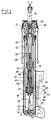
- Figure 1 is a longitudinal section of a shock absorber according to a first embodiment of the present invention ;
- Figure 2 is an enlarged view of that part of Figure 1 indicated by
reference arrow 2 ; - Figures 3A and 3B are longitudinal sections of a shock absorber which corresponds to the invention claimed with the exception that the chamber is on the valve member and not on the core member.
- As shown in Figure 1. the variable rate shock absorber comprises a cylindrical
outer shell 10 to which is secured abracket 12 by means of which theshell 10 may be mounted on a support for one of a vehicle's wheels (not shown). Aninner cylinder 14 is fixedly mounted inside theshell 10 and is closed at oneend 15 by a two way pressurerelief valve member 16 which connects the interior of theinner cylinder 14 with anannular reservoir 18 formed between theinner cylinder 14 and theouter shell 10. The other end 20 of theinner cylinder 14 is closed relative to theouter shell 10 by a closure member 22. - The shock absorber further comprises a
piston rod assembly 24 which is slideably received in the closure member 22 and extends within theinner cylinder 14, coaxially therewith. Thepiston rod assembly 24 comprises atubular strut 26 in oneend 28 of which is fitted amounting member 30, theother end 32 of which being closed by amounting bolt 34 whose free end is intended to be secured to the bodywork of the vehicle (not shown). Themounting member 30 also sealingly receives an end of acylinder 36 and further receives, slidingly, a secondcylindrical part 38 oneend 40 of which is fixedly mounted in thevalve member 16 and passes therethrough. Thecylinder 36 and thecylindrical part 38 are free to slide in telescoping fashion one relative to the other. At least oneaperture 42 is provided in thetubular strut 26 adjacent themounting member 30 to provide fluid communication between theannular volume 44 defined within theinner cylinder 14 and theannular space 46 defined between thetubular strut 26 and thecylinder 36. - The
mounting member 30 supports apiston member 48 which is slideably received within theinner cylinder 14. Thepiston member 48 is secured on themounting member 30 by anut 50 and has a set of throughpassages 52 which are open at one end and closed at the opposite end by a spring loadedvalve 54 which allows one-way fluid flow between theannular volume 44 and aworking chamber 56 formed at an end of theinner cylinder 14. Thepiston member 48 has a second set of throughpassages 58 which are open to the workingchamber 56 and closed at their opposite end by a second spring loadedvalve 60 to provide unidirectional flow from thelower working chamber 56 to theannular volume 44. - The
valve member 16, mounted under pressure between thecylinder 14 and theouter shell 10, containsseveral passages valves springs permanent passages passages springs permanent passages 52 and, their diameter and the resilience of the spring loadedvalve 54 in thepiston member 48 and the diameter of thepassages 19 and the resilience ofvalve 23 in thevalve member 16. In the compression movements of the shock absorber, the parts defining said characteristic and thepermanent passages 12 and their diameter and, the resilience of the spring loadedvalve 21 in thevalve member 16, and the diameter of thepassages 58 and the second spring loadedvalve 60 in thepiston member 48. - Figure 2 shows details of an embodiment of
solenoid valve 62. As shown, thesolenoid valve 62 comprises asolenoid coil 64 which is selectively connectable by anelectric cable 66 to a controlling power source (not shown). Thesolenoid coil 64 is formed around acore member 68 one end of which is fixedly mounted on themounting bolt 34 and the other end sealingly and slideably receives thefree end 74 ofcylinder 36. Thecore member 68 is formed from two parts ofmagnetic material ring 76 of non-magnetic material, for example bronze. Anannular air gap 78 is defined between the opposing edges of the twoparts core member 68. - A
cylindrical valve member 80 is slideably mounted in alongitudinal bore 82 formed in thecore member 68 and has a length such that, in the illustrated rest position, an end of thevalve member 80 is immediately adjacent the leadingedge 84 ofpart 70 of thecore member 68. Thevalve member 80 is urged towards its illustrated rest position by a spring 86 which is located between twonon-magnetic bushes 88 and 90. At its end remote from spring 86 thevalve member 80 has a longitudinally extendinggroove 92 which communicates by way ofpassage 94 with a longitudinal bore 96 extending through thevalve member 80. The bore 96 is in fluid communication with theinterior 98 ofcylinder 36. When thesolenoid coil 64 is actuated and thevalve member 80 moves against the force of spring 86, the closed end ofgroove 92 comes into fluid communication with apassageway 102 formed inpart 72 ofcore member 68. Actuation of thesolenoid coil 64 thus causes a fluid passageway to be opened between theinterior 98 ofcylinder 36 and theannular space 46. - In use the
annular volume 44 and theworking chamber 56 are filled with a hydraulic fluid while theannular reservoir 18 is only partially filled with hydraulic fluid. The remaining portion of theannular reservoir 18 is filled with air or gas at a pressure above or equal to atomospheric pressure. - In operation, the
piston member 48 will assume a nominal position intermediate the extremities of theinner cylinder 14. In the event that the wheel associated with the shock absorber encounters a bump, a force will be applied to the free end of the shock absorber tending to displace theouter shell 10 andinner cylinder 14 upwardly towards themounting bolt 34 attached to vehicle's frame. This force will produce a pressure differential across thepiston member 48. If the wheel associated with the shock absorber falls into a hole, the free end of the shock absorber will be subjected to a force tending to displace theouter shell 10 and theinner cylinder 14 vertically downwards, away from themounting bolt 34 which is secured to the bodywork of the vehicle, with the shock absorber in extension. This force will cause a pressure differential across thepiston member 48 and the spring loadedvalve 54, causing the oil to flow through thepermanent passage 52 of thepiston member 48, which will allow the said movement. In turn, the pressure differential across thevalve member 16 will cause the oil to flow between theannular reservoir 18 and workingchamber 56 which will compensate for the volume increase formed by the extension of the shock absorber. - When the wheel encounters a bump, the operation of the shock absorber is symmetrical to that indicated above, the roles of the
valve member 16 and thepiston member 48 being reversed. - When the wheel falls into a hole and the solenoid valve is not activated, the fluid pressure is maximum in the
annular volume 44, the oil being compressed between the upper seal and the piston, rising towards the former, the shock absorber being extended. - The stiffness of the shock absorber can be changed by activating the
solenoid valve 62 to vent theannular volume 44 to thereservoir 18 through thecylinder 36 and thecylindrical part 38. - Referring to Figure 2, when the
solenoid coil 64 is not activated thevalve member 80 is urged by spring 86 into its rest position in abutment against aring 104 fixedly mounted in thebore 82 ofcore member 68. In thisposition passageway 102 is closed by thevalve member 80. - Activation of the
solenoid coil 64 causes thevalve member 80 to move against the force of spring 86 towards a position in which ashoulder 106 on an end of thevalve member 80 comes into contact with anannular abutment 108 formed in thebore 82. The controlled displacement ofvalve member 80 opens a controlled fluid passage between theinterior 98 ofcylinder 36, which is in fluid communication with the interior ofcylindrical part 38 and theannular space 46. - When the wheel encounters a bump and the solenoid valve is not activated, the fluid pressure is a maximum in the
chamber 56 and since the diameters of thepassages springs valve member 16 is greater than through the piston, then the pressure in theannular volume 44 is greater than that of thereservoir 18. - Since the fluid flow through the
passages 58 is proportional to the pressure differential across thepiston member 48, during extension, the movement of the piston member is controlled by the pressure in theannular volume 44. Activation of thesolenoid valve 62 evacuates theannular volume 44 to thereservoir 18, thereby reducing the pressure differential in thepiston member 48. As a result, the fluid flow through the piston is lower, the energy dissipation by viscous friction through the piston is lower whereby the stiffness of the shock absorber in extension is reduced. - During compression, the displacement of the piston is controlled by the pressure in the
chamber 56 and the pressure differential across thevalve member 16. Activation of thesolenoid valve 62 evacuates theannular volume 44, the pressure of which is greater, to thereservoir 18, the pressure of which is lower, thereby increasing the pressure differential across the piston. In this way the flow rate from thechamber 56 to theannular volume 44 increases and the pressure in thechamber 56 is reduced. Thereby the pressure differential across the valve member decreases, the energy disipation by viscous friction thereacross is less, which reduces the stiffness of the shock absorber in compression. - In this way the solenoid valve controlling the fluid flow rate from the
annular volume 44 to thereservoir 18 may be used to reduce the stiffness of the shock absorber in the desired degree when the valve is open, both in the extension and in the compression movements. - During the rebound or when the wheel falls into a hole, a force is generated tending to displace the housing and inner cylinder downwardly away from mounting
bolt 34. This force increases the fluid pressure in theannular volume 44 above thepiston member 48. When thesolenoid valve 62 is actuated, theannular volume 44 is vented to thereservoir 18. Therefore, the movement of thepiston member 48 is controlled primarily by the fluid flowtrough relief valve 16 from thereservoir 18 to the workingchamber 56. The size of the fluid passages of therelief valve 16 which control the rate of fluid flow from thereservoir 18 to the workingchamber 56 can be selected to decrease the stiffness of the shock absorber by the desired amount when the solenoid valve is open. - As shown in Figure 2 the
longitudinally extending groove 92 has an end 112 extending at right angles to theaxis 114 of thevalve member 80. In the illustrated rest position the end 112 lies adjacent an edge of achamfered surface 116 which leads to thepassageway 102. - The chamfered
surface 116 lies on thecore member 68 which has the result that a force F is exerted on the fixedcore member 68. The force F has virtually no influence on the throttling value. - Figures 3a and 3b show a variant in which the internal structure of the shock absorber has been simplified with respect to that shown in Figure 1. The
solenoid valve 62 is located in anextension 401 of theouter shell 10 as opposed to in thetubular strut 26 in the previous embodiment. The shock absorber comprises a singleinner tube 403 which corresponds to the secondcylindrical part 38 of the embodiment of Figure 1 in which two telescoping tubes were necessary due to the location of the solenoid valve. - The
inner tube 403 is received in asleeve 405 which is fixed in, and passes through thevalve member 16. The interior of theinner tube 403 communicates with the interior of the slidingvalve member 80 of thesolenoid valve 62. As in the case of the previous embodiment, when thesolenoid coil 64 is actuated,valve member 80 moves against spring 86 and progressively openspassageway 102 between the interior of theinner tube 403 and achamber 407 which is defined by theextension 401 of theouter shell 10. Thechamber 407 is in permanent communication with theannular reservoir 18 and may communicate with the working chamber, as in the case of the previous embodiment, by way ofpassages inner tube 403 is in fluid communication with theannular space 46 which is, itself, in fluid communication with theannular volume 44 by way ofaperture 42. - The operation of this embodiment is analogous to that of the embodiment of Figure 1.
Claims (5)
- A variable rate shock absorber comprising a tubular working cylinder (14) destined to be mounted on a suspended part of a vehicle, a piston rod assembly (24) slideably received in the working cylinder (14) and having an end (34) destined to be mounted on a fixed part of a vehicle, the piston rod assembly having at its free end a piston member (48) cooperating with the working cylinder (14) to divide the interior thereof into an upper (44) and a lower working chamber (56), valve means in the piston member (48) to permit controlled two-way flow between the upper (44) and lower (56) working chambers, and solenoid valve means (62) disposed between one of the working chambers and an annular space (18) and selectively actuatable to allow fluid flow therebetween, the solenoid valve means (62) comprising a tubular valve member (80) slideably mounted with respect to a core member (68) and slideable in response to actuation of a solenoid coil (64) generating a magnetic field to open an orifice (102), characterized
in that said core member (68) is formed from two parts (70, 72) of magnetic material which are separated by a non-magnetic material so that the valve member (80) closes the generated magnetic field between said two parts (70, 72),
in that said valve member (80) is progressively displaceable against a spring (86) under the effect of the magnetic induction produced by said solenoid coil (64) in order to variably open said orifice (102) between a fully closed and a fully open position, and
in that the tubular valve member (80) is mounted in a bore (82) formed in the core member (68), the core member (68) having an opening (102) therein which is defined in part by a chamfered surface (116), the valve member (80) having an edge (112) which cooperates with the chamfered surface (116) to form the said variable orifice. - A shock absorber as claimed in Claim 1, characterised in that it further comprises an outer shell (10) circumscribing the working cylinder (14) and defining therebetween a reservoir (18), valve means (16), located at an end of the working cylinder (14) defining an extremity of the lower working chamber (56) and allowing controlled two-way flow between the lower working chamber (56) and the reservoir (18), the solenoid valve means (62) being located in an independant passage (36,38 ; 403) between the upper working chamber (44) and the reservoir (18).
- A shock absorber as claimed in Claim 2, characterised in that the passage (36,38) comprises two telescopingly arranged tubes (36,38) extending through an axial passage (46) in the piston rod assembly (24).
- A shock absorber as claimed in Claim 2, characterised in that the passage (403) comprises a tube (403) one end of which is mounted on the valve means (16) the other end of which is slideably received in an axial passage (46) in the piston rod assembly (24).
- A shock absorber as claimed in Claim 4, characterised in that the solenoid valve means (62) is located in a chamber (407) formed in an extension of the outer shell (10) defined on the opposite side of the valve means (16) to the lower working chamber (56), the chamber (407) being in fluid communication with the reservoir (18).
Priority Applications (5)
| Application Number | Priority Date | Filing Date | Title |
|---|---|---|---|
| DE8787500039TDE3781147T2 (en) | 1987-06-19 | 1987-06-19 | ADJUSTABLE SHOCK ABSORBER. |
| EP87500039AEP0297194B1 (en) | 1987-06-19 | 1987-06-19 | Variable rate shock absorber |
| ES198787500039TES2033914T3 (en) | 1987-06-19 | 1987-06-19 | VARIABLE SHOCK ABSORBER. |
| US07/207,689US4832162A (en) | 1987-06-19 | 1988-06-16 | Variable rate shock absorber |
| JP63148399AJPH0257740A (en) | 1987-06-19 | 1988-06-17 | Damping-force variable type shock absorber |
Applications Claiming Priority (1)
| Application Number | Priority Date | Filing Date | Title |
|---|---|---|---|
| EP87500039AEP0297194B1 (en) | 1987-06-19 | 1987-06-19 | Variable rate shock absorber |
Publications (2)
| Publication Number | Publication Date |
|---|---|
| EP0297194A1 EP0297194A1 (en) | 1989-01-04 |
| EP0297194B1true EP0297194B1 (en) | 1992-08-12 |
Family
ID=8198341
Family Applications (1)
| Application Number | Title | Priority Date | Filing Date |
|---|---|---|---|
| EP87500039AExpired - LifetimeEP0297194B1 (en) | 1987-06-19 | 1987-06-19 | Variable rate shock absorber |
Country Status (5)
| Country | Link |
|---|---|
| US (1) | US4832162A (en) |
| EP (1) | EP0297194B1 (en) |
| JP (1) | JPH0257740A (en) |
| DE (1) | DE3781147T2 (en) |
| ES (1) | ES2033914T3 (en) |
Families Citing this family (20)
| Publication number | Priority date | Publication date | Assignee | Title |
|---|---|---|---|---|
| US4949989A (en)* | 1988-04-19 | 1990-08-21 | Atsugi Motor Parts Co., Ltd. | Automotive suspension system with variable suspension characteristics and variable damping force shock absorber therefor |
| DE3830343A1 (en)* | 1988-09-07 | 1990-03-08 | Fichtel & Sachs Ag | DAMPING FORCE CHANGEABLE, HYDRAULIC VIBRATION DAMPER |
| US5158161A (en)* | 1989-07-17 | 1992-10-27 | Atsugi Unisia Corporation | Reverse installation type variable damping force shock absorber variable of damping characteristics both for bounding and rebounding stroke motions |
| US5129488A (en)* | 1989-11-16 | 1992-07-14 | Atsugi Unisia Corporation | Vibration mode responsive variable damping force shock absorber with feature of automatic selection of damping mode depending upon vibration mode of vehicular body |
| US5113979A (en)* | 1991-02-20 | 1992-05-19 | Monroe Auto Equipment Company | Base valve for a shock absorber |
| US5163538A (en)* | 1991-09-03 | 1992-11-17 | General Motors Company | Low level damping valve and method for a semi-active hydraulic damper |
| US5328004A (en)* | 1992-08-21 | 1994-07-12 | General Motors Corporation | Bypass valve assembly for a hydraulic damper |
| US5282645A (en)* | 1992-11-25 | 1994-02-01 | General Motors Corporation | Electro-hydraulic pressure regulating valve assembly mounted in a valve boss on a hydraulic damper |
| US5511759A (en)* | 1994-05-26 | 1996-04-30 | Steelcase, Inc. | Hydraulic chair height adjustment mechanism |
| US5797594A (en)* | 1995-07-22 | 1998-08-25 | Tokico, Ltd. | Hydraulic shock absorber |
| DE19624898C2 (en)* | 1996-06-21 | 1998-07-02 | Mannesmann Sachs Ag | Damping valve with variable damping force |
| DE29714681U1 (en)* | 1997-08-16 | 1997-10-16 | Festo AG & Co, 73734 Esslingen | Fluid operated cylinder |
| ES2209659B1 (en)* | 1999-08-04 | 2005-06-16 | Quinton Hazell Espana, S.A. | PERFECTED VARIABLE REGIME SHOCK ABSORBER. |
| WO2001011255A1 (en)* | 1999-08-04 | 2001-02-15 | Quinton Hazell España, S.A. | Improved variable operation shock-absorber |
| EP1363042B1 (en)* | 2001-02-23 | 2004-10-27 | Quinton Hazell Espana, S.A. | Adjustable shock absorber |
| DE10260395B3 (en)* | 2002-12-21 | 2004-06-09 | Zf Sachs Ag | Hydraulic oscillation damper with adjustable damping valve and vented hollow space defined by piston rod and displacement rod secured to damping cylinder base |
| US6918473B2 (en)* | 2003-09-17 | 2005-07-19 | Tenneco Automotive Operating Company Inc. | Stroke dependent bypass |
| CN103228945B (en)* | 2010-09-28 | 2016-06-22 | 诺格伦有限责任公司 | Damping cylinder |
| US20140263915A1 (en)* | 2013-03-12 | 2014-09-18 | Robert Henry Bernacki | Rapid Deploy Manually Operated Extendible Strut |
| JP7212552B2 (en)* | 2019-03-04 | 2023-01-25 | Kyb株式会社 | buffer |
Citations (1)
| Publication number | Priority date | Publication date | Assignee | Title |
|---|---|---|---|---|
| JPS59147134A (en)* | 1983-02-09 | 1984-08-23 | Nissan Motor Co Ltd | Variable damping force shock absorber |
Family Cites Families (14)
| Publication number | Priority date | Publication date | Assignee | Title |
|---|---|---|---|---|
| US2507276A (en)* | 1947-12-17 | 1950-05-09 | Skwaryk Frank | Stabilizing device |
| US3039566A (en)* | 1960-01-29 | 1962-06-19 | Houdaille Industries Inc | Linear hydraulic shock absorber |
| US4463839A (en)* | 1981-11-06 | 1984-08-07 | Tokico Ltd. | Hydraulic damper |
| JPS58128982A (en)* | 1982-01-25 | 1983-08-01 | カヤバ工業株式会社 | Hydraulic shock absorber |
| DE8221257U1 (en)* | 1982-07-26 | 1985-10-31 | F & O Electronic Systems GmbH & Co, 6901 Neckarsteinach | Adjustable vibration damper, in particular for motor vehicles |
| ES8503803A1 (en)* | 1983-06-29 | 1985-03-01 | Boge Gmbh | Adjustable hydraulic damper apparatus |
| DE3406875A1 (en)* | 1984-02-25 | 1985-09-05 | Boge Gmbh, 5208 Eitorf | VIBRATION DAMPER FOR VEHICLES |
| DE3419879C2 (en)* | 1984-05-28 | 1987-01-02 | Boge Gmbh, 5208 Eitorf | Hydraulic, adjustable twin-tube vibration damper |
| DE3434877A1 (en)* | 1984-09-22 | 1986-04-17 | Boge Gmbh, 5208 Eitorf | HYDRAULIC, ADJUSTABLE SHOCK ABSORBER |
| US4685545A (en)* | 1984-12-24 | 1987-08-11 | General Motors Corporation | Hydraulic damper for vehicles with variable orifice piston valving for varying damping force |
| JPS61153031A (en)* | 1984-12-27 | 1986-07-11 | Toyota Motor Corp | Hydraulic draft gear |
| DE3528341C1 (en)* | 1985-08-07 | 1986-05-22 | F & O Electronic Systems GmbH & Co, 6901 Neckarsteinach | Adjustable valve for the piston rod of a vibration damper |
| DE3535287A1 (en)* | 1985-10-03 | 1987-04-16 | Boge Gmbh | VIBRATION DAMPING SYSTEM FOR VEHICLES |
| US4682675A (en)* | 1985-11-25 | 1987-07-28 | Allied Corporation | Variable rate shock absorber |
- 1987
- 1987-06-19DEDE8787500039Tpatent/DE3781147T2/ennot_activeExpired - Lifetime
- 1987-06-19EPEP87500039Apatent/EP0297194B1/ennot_activeExpired - Lifetime
- 1987-06-19ESES198787500039Tpatent/ES2033914T3/ennot_activeExpired - Lifetime
- 1988
- 1988-06-16USUS07/207,689patent/US4832162A/ennot_activeExpired - Lifetime
- 1988-06-17JPJP63148399Apatent/JPH0257740A/enactivePending
Patent Citations (1)
| Publication number | Priority date | Publication date | Assignee | Title |
|---|---|---|---|---|
| JPS59147134A (en)* | 1983-02-09 | 1984-08-23 | Nissan Motor Co Ltd | Variable damping force shock absorber |
Non-Patent Citations (2)
| Title |
|---|
| "Der Hydraulik Trainer" Vogel Verlag, Würzburg 1980, Seite 143-148 (D11)* |
| "Einführung in die Hydraulik und Pneumatik" VEB Verlag Technik, Berlin, 1981; Seite 154, 155, 176, 181 (D10)* |
Also Published As
| Publication number | Publication date |
|---|---|
| DE3781147T2 (en) | 1993-03-04 |
| DE3781147D1 (en) | 1992-09-17 |
| ES2033914T3 (en) | 1993-04-01 |
| EP0297194A1 (en) | 1989-01-04 |
| JPH0257740A (en) | 1990-02-27 |
| US4832162A (en) | 1989-05-23 |
Similar Documents
| Publication | Publication Date | Title |
|---|---|---|
| EP0297194B1 (en) | Variable rate shock absorber | |
| EP0313708B1 (en) | Shock absorber | |
| EP1664578B1 (en) | Stroke dependent bypass | |
| EP1158202B2 (en) | Independently tunable variable bleed orifice | |
| US5934422A (en) | Step motor actuated continuously variable shock absorber | |
| US6321888B1 (en) | Damper with externally mounted semi-active system | |
| EP3039312B1 (en) | Shock absorber with frequency dependent passive valve | |
| US5503258A (en) | Hydraulic shock absorber | |
| US7216747B2 (en) | Amplitude controlled orifice valving | |
| US6290035B1 (en) | Acceleration sensitive damping for automotive dampers | |
| US5911290A (en) | Step motor actuated continuous variable shock absorber | |
| US5533596A (en) | Hydraulic, adjustable vibration damper for motor vehicles | |
| GB2349681A (en) | Stroke dependent bypass | |
| EP3830444B1 (en) | Variable-damping hydraulic shock-absorber for a vehicle suspension | |
| CA2100210A1 (en) | Adjustable dampers using electrorheological fluids | |
| EP0660008A2 (en) | Shock absorber with hydraulic rebound stop | |
| EP0572040A1 (en) | Method and apparatus for absorbing mechanical shock | |
| EP0328843A1 (en) | Variable rate shock absorber | |
| GB2244539A (en) | Variable damping force shock absorber | |
| JP2823963B2 (en) | Hydraulic damper | |
| JP2559254Y2 (en) | Front fork | |
| GB2378231A (en) | A damper for a vehicle suspension with externally mounted semi-active system | |
| EP1241372A3 (en) | Hydraulic damper for a vehicle suspension system | |
| GB2310023A (en) | Hydraulic Damper | |
| US5462143A (en) | Controllable shock absorber for motor vehicles |
Legal Events
| Date | Code | Title | Description |
|---|---|---|---|
| PUAI | Public reference made under article 153(3) epc to a published international application that has entered the european phase | Free format text:ORIGINAL CODE: 0009012 | |
| AK | Designated contracting states | Kind code of ref document:A1 Designated state(s):DE ES FR GB IT SE | |
| 17P | Request for examination filed | Effective date:19881209 | |
| 17Q | First examination report despatched | Effective date:19890515 | |
| GRAA | (expected) grant | Free format text:ORIGINAL CODE: 0009210 | |
| AK | Designated contracting states | Kind code of ref document:B1 Designated state(s):DE ES FR GB IT SE | |
| ITF | It: translation for a ep patent filed | ||
| REF | Corresponds to: | Ref document number:3781147 Country of ref document:DE Date of ref document:19920917 | |
| ET | Fr: translation filed | ||
| PLBI | Opposition filed | Free format text:ORIGINAL CODE: 0009260 | |
| REG | Reference to a national code | Ref country code:ES Ref legal event code:PC2A Owner name:LA INDUSTRIAL PLASTICA Y METALURGICA, S.A. | |
| 26 | Opposition filed | Opponent name:FICHTEL & SACHS AG Effective date:19930508 | |
| REG | Reference to a national code | Ref country code:FR Ref legal event code:TP | |
| REG | Reference to a national code | Ref country code:GB Ref legal event code:732E | |
| RAP2 | Party data changed (patent owner data changed or rights of a patent transferred) | Owner name:LA INDUSTRIAL PLASTICA Y METALURGICA, S.A. | |
| RAP2 | Party data changed (patent owner data changed or rights of a patent transferred) | Owner name:LA INDUSTRIAL PLASTICA Y METALURGICA, S.A. | |
| ITPR | It: changes in ownership of a european patent | Owner name:ASSUNZIONE O VARIAZIONE MANDATO;STUDIO CONSULENZA | |
| EAL | Se: european patent in force in sweden | Ref document number:87500039.0 | |
| PLBN | Opposition rejected | Free format text:ORIGINAL CODE: 0009273 | |
| STAA | Information on the status of an ep patent application or granted ep patent | Free format text:STATUS: OPPOSITION REJECTED | |
| 27O | Opposition rejected | Effective date:19951001 | |
| REG | Reference to a national code | Ref country code:GB Ref legal event code:IF02 | |
| PGFP | Annual fee paid to national office [announced via postgrant information from national office to epo] | Ref country code:SE Payment date:20050607 Year of fee payment:19 | |
| APAH | Appeal reference modified | Free format text:ORIGINAL CODE: EPIDOSCREFNO | |
| PGFP | Annual fee paid to national office [announced via postgrant information from national office to epo] | Ref country code:ES Payment date:20060404 Year of fee payment:20 | |
| PG25 | Lapsed in a contracting state [announced via postgrant information from national office to epo] | Ref country code:SE Free format text:LAPSE BECAUSE OF NON-PAYMENT OF DUE FEES Effective date:20060620 | |
| PGFP | Annual fee paid to national office [announced via postgrant information from national office to epo] | Ref country code:IT Payment date:20060630 Year of fee payment:20 | |
| PGFP | Annual fee paid to national office [announced via postgrant information from national office to epo] | Ref country code:GB Payment date:20060719 Year of fee payment:20 | |
| PGFP | Annual fee paid to national office [announced via postgrant information from national office to epo] | Ref country code:FR Payment date:20060724 Year of fee payment:20 | |
| PGFP | Annual fee paid to national office [announced via postgrant information from national office to epo] | Ref country code:DE Payment date:20060830 Year of fee payment:20 | |
| EUG | Se: european patent has lapsed | ||
| PG25 | Lapsed in a contracting state [announced via postgrant information from national office to epo] | Ref country code:ES Free format text:LAPSE BECAUSE OF EXPIRATION OF PROTECTION Effective date:20070620 | |
| REG | Reference to a national code | Ref country code:GB Ref legal event code:PE20 | |
| REG | Reference to a national code | Ref country code:ES Ref legal event code:FD2A Effective date:20070620 | |
| PG25 | Lapsed in a contracting state [announced via postgrant information from national office to epo] | Ref country code:GB Free format text:LAPSE BECAUSE OF EXPIRATION OF PROTECTION Effective date:20070618 |