EP0296397B1 - Power transmitting v-belt - Google Patents
Power transmitting v-beltDownload PDFInfo
- Publication number
- EP0296397B1 EP0296397B1EP88108943AEP88108943AEP0296397B1EP 0296397 B1EP0296397 B1EP 0296397B1EP 88108943 AEP88108943 AEP 88108943AEP 88108943 AEP88108943 AEP 88108943AEP 0296397 B1EP0296397 B1EP 0296397B1
- Authority
- EP
- European Patent Office
- Prior art keywords
- semi
- power transmitting
- cylindrical
- shaped metal
- belt
- Prior art date
- Legal status (The legal status is an assumption and is not a legal conclusion. Google has not performed a legal analysis and makes no representation as to the accuracy of the status listed.)
- Expired
Links
- 239000002184metalSubstances0.000claimsdescription51
- 229910052751metalInorganic materials0.000claimsdescription51
- 239000000956alloySubstances0.000claimsdescription4
- 229910045601alloyInorganic materials0.000claimsdescription4
- 230000004323axial lengthEffects0.000claims1
- 238000010276constructionMethods0.000description3
- 239000000463materialSubstances0.000description3
- XEEYBQQBJWHFJM-UHFFFAOYSA-NIronChemical compound[Fe]XEEYBQQBJWHFJM-UHFFFAOYSA-N0.000description2
- 238000005461lubricationMethods0.000description2
- 238000005245sinteringMethods0.000description2
- 238000007669thermal treatmentMethods0.000description2
- 230000005540biological transmissionEffects0.000description1
- 230000000295complement effectEffects0.000description1
- 238000000280densificationMethods0.000description1
- 230000000694effectsEffects0.000description1
- 229910052742ironInorganic materials0.000description1
- 239000000314lubricantSubstances0.000description1
- 230000001050lubricating effectEffects0.000description1
- 238000003754machiningMethods0.000description1
- 230000002265preventionEffects0.000description1
Images
Classifications
- F—MECHANICAL ENGINEERING; LIGHTING; HEATING; WEAPONS; BLASTING
- F16—ENGINEERING ELEMENTS AND UNITS; GENERAL MEASURES FOR PRODUCING AND MAINTAINING EFFECTIVE FUNCTIONING OF MACHINES OR INSTALLATIONS; THERMAL INSULATION IN GENERAL
- F16G—BELTS, CABLES, OR ROPES, PREDOMINANTLY USED FOR DRIVING PURPOSES; CHAINS; FITTINGS PREDOMINANTLY USED THEREFOR
- F16G5/00—V-belts, i.e. belts of tapered cross-section
- F16G5/16—V-belts, i.e. belts of tapered cross-section consisting of several parts
Definitions
- the present inventionrelates to a power transmitting V-belt and, more particularly, to a power transmitting V-belt for use in combination with a variable diameter V-pulley.
- V-beltsfor use in V-belt type continuously variable transmissions for vehicles that employ variable diameter V-pulleys.
- V-beltsnormally are comprised of a metal band which is formed of a plurality of endless laminated metal band elements and which are restrained and held by a large number of V-shaped metal blocks provided adjacent one another.
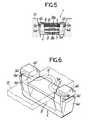
- Fig. 6illustrates a perspective view of a V-shaped metal block in a V-belt of this type disclosed in US-A-4 522 548.
- the prior art V-shaped metal block 4' shown in Fig. 6has a recessed groove 5' that is open upwardly with a bottom surface of the recessed groove 5' being formed as a support surface 5a' bearing against a lower surface of a metal band B', shown by one-dash chain line, to support the band.
- the metal block 4'is also provided, at its opposite side surfaces, as viewed in a lengthwise direction of the metal band B', with widthwise extending semi-cylindrical recesses 8'.
- a roller memberis interposed between the opposed recesses 8'of the adjacent metal blocks to provide an assembled V-belt.
- one of the two recesses 8' on the metal block 4'may be replaced by a semi-cylindrical projection which is directly engaged in the semi-cylindrical recess of the adjacent metal block.
- the V-shaped metal block 4'has a pair of inclined portions 4a', 4a' formed at its opposite ends, as viewed in the widthwise direction of the band B' that are adapted to engage a V-groove of a V-pulley which is not shown.
- the block 4'has an upper wall 4b', a transverse groove 9a' extending in a lengthwise direction of the band, and a vertical groove 9b' extending in the direction of the thickness of the band for receiving a wire stopper member 6', indicated by one-dash chain line, which is locked at its opposite ends, so that the metal band B' placed on the support surface 5a' is restrained and held on the support surface 5a' by the stopper member 6'.
- the transverse and vertical grooves 9a' and 9b'form a curved slot 9' for locking the stopper member.
- the above constructionprovides an advantage that the height of the upper wall 4b',i.e., the entire height of the metal block itself, can be reduced but the following problems still remain unsolved. More specifically, in producing the metal bock of such a complicated shape, for example from a sintered alloy, the semi-cylindrical recesses 8' located on the front and rear opposite side surfaces are shaped using complementary convex dies and hence the central portion of each of the recesses 8' of the metal block 4' tends to have a high density of material. For this reason, a phenomenon of expansion of the central portion may be produced in the course of sintering and thermal treatment steps.
- roller memberwhen the roller member is interposed between the respective proposed recesses 8' of the two adjacent V-shaped metal blocks, the roller member bears only against the central portions of the recesses 8' and is not in uniform contact with the recesses over the entire axial region thereof.
- roller membersince the roller member is relatively long, it is difficult to obtain uniform lubrication of the roller member along its entire length.
- V-beltaccording to the characterizing part of claim 1, which provides V-shaped blocks with relief portions for minimizing the engagement between recess and projection.
- a metal band Bis comprised of a plurality of endless laminated metal band elements Ba and has a bottom surface bearing on a support surface 5a which forms a bottom surface of an upwardly opened recessed groove 5 for receiving the metal band B in each of a large number of V-shaped metal blocks 4.
- a wire stopper member 6is locked at its opposite ends in a transverse groove 9a and a vertical groove 9b of a locking slot 9 to restrain and hold the metal band B.
- a roller member 7is interposed between opposed semi-cylindrical recesses 8 provided on the opposite side surfaces, as viewed in the lengthwise direction of the band B, of adjacent V-shaped metal blocks 4.
- the roller member 7may be cylindrical or at least provided with a pair of oppositely facing semi-cylindrical projections engaging the semi-cylindrical recesses.
- a V-belt 1 of this embodimentis comprised of the metal band B, a large number of the V-shaped metal blocks 4, a large number of the roller members 7 and a large number of the stopper members 6.
- the V-shaped metal block 4is similar in basic structure to the prior art V-shaped metal block shown in Fig. 6 and has the recessed groove 5 between the opposite upper walls 4b, 4b thereof and a pair of inclined portions 4a, 4a formed at its opposite side surfaces, as viewed in the widthwise direction of the band B adapted to engage a V-groove of a V-pulley 10.
- a semi-cylindrical recess or relief portion 8a having a certain axial widthis provided at an axially central portion of each of the semi-cylindrical recesses 8 of each of the V-shaped metal blocks 4.
- the relief portionhas a radius R2 slightly larger than the radius R1 of the recess 8 (see Figs. 1 and 2). Therefore, the relief portion 8a is formed on the metal block 4 to be recessed more deeply than the recess 8.
- the provision of the suitable relief portion 8a at the central portion of each of the pair of recesses 8 in the V-shaped metal block 4makes it possible to compensate for any expansion of the metal at the central portion during sintering and thermal treatment due to the densification of the material when such metal block 4 is formed, for example, from a sintered alloy using complemental convex dies. Moreover, it is possible to prevent the generation of high surface pressure at the central portion due to an uneven contact with the roller member 7 and seizure due to failure of lubrication during use of the V-belt.
- This constructionpermits the use of, for example, an iron-based sintered alloy as a material for such a block of a complicated shape which avoids the costly conventional machining otherwise required.
- a sintered product previously impregnated with a lubricant in a so-called oilless (oil impregnated) bearing manner utilizing a porous structure, which is a characteristic thereof,can considerably improve the lubricity to reduce the frictional force and further contribute to prevention of a seizure or the like.
Landscapes
- Engineering & Computer Science (AREA)
- General Engineering & Computer Science (AREA)
- Mechanical Engineering (AREA)
- Powder Metallurgy (AREA)
- Pulleys (AREA)
- Transmissions By Endless Flexible Members (AREA)
Description
- The present invention relates to a power transmitting V-belt and, more particularly, to a power transmitting V-belt for use in combination with a variable diameter V-pulley.
- There are various conventional power-transmitting V-belts for use in V-belt type continuously variable transmissions for vehicles that employ variable diameter V-pulleys. Such V-belts normally are comprised of a metal band which is formed of a plurality of endless laminated metal band elements and which are restrained and held by a large number of V-shaped metal blocks provided adjacent one another. Fig. 6 illustrates a perspective view of a V-shaped metal block in a V-belt of this type disclosed in US-A-4 522 548.
- The prior art V-shaped metal block 4' shown in Fig. 6 has a recessed groove 5' that is open upwardly with a bottom surface of the recessed groove 5' being formed as a
support surface 5a' bearing against a lower surface of a metal band B', shown by one-dash chain line, to support the band. The metal block 4' is also provided, at its opposite side surfaces, as viewed in a lengthwise direction of the metal band B', with widthwise extending semi-cylindrical recesses 8'. A roller member is interposed between the opposed recesses 8'of the adjacent metal blocks to provide an assembled V-belt. - Alternatively, without interposition of such roller members, one of the two recesses 8' on the metal block 4' may be replaced by a semi-cylindrical projection which is directly engaged in the semi-cylindrical recess of the adjacent metal block.
- In addition, the V-shaped metal block 4' has a pair of
inclined portions 4a', 4a' formed at its opposite ends, as viewed in the widthwise direction of the band B' that are adapted to engage a V-groove of a V-pulley which is not shown. The block 4' has anupper wall 4b', atransverse groove 9a' extending in a lengthwise direction of the band, and avertical groove 9b' extending in the direction of the thickness of the band for receiving a wire stopper member 6', indicated by one-dash chain line, which is locked at its opposite ends, so that the metal band B' placed on thesupport surface 5a' is restrained and held on thesupport surface 5a' by the stopper member 6'. The transverse andvertical grooves 9a' and 9b' form a curved slot 9' for locking the stopper member. - The above construction provides an advantage that the height of the
upper wall 4b',i.e., the entire height of the metal block itself, can be reduced but the following problems still remain unsolved. More specifically, in producing the metal bock of such a complicated shape, for example from a sintered alloy, the semi-cylindrical recesses 8' located on the front and rear opposite side surfaces are shaped using complementary convex dies and hence the central portion of each of the recesses 8' of the metal block 4' tends to have a high density of material. For this reason, a phenomenon of expansion of the central portion may be produced in the course of sintering and thermal treatment steps. In such a case, when the roller member is interposed between the respective proposed recesses 8' of the two adjacent V-shaped metal blocks, the roller member bears only against the central portions of the recesses 8' and is not in uniform contact with the recesses over the entire axial region thereof. - In addition, since the roller member is relatively long, it is difficult to obtain uniform lubrication of the roller member along its entire length.
- Even with the metal block in which the roller member is omitted and one of the recesses is replaced by the semi-cylindrical projection, the above problems have a similar tendency to occur with respect to the other recess.
- It is an object of the present invention to provide a power transmitting V-belt in which a uniform contact is achieved in the recesses of the adjacent V-shaped metal blocks and the lubricating condition is improved.
- This object is reached with a power transmitting V-belt according to the characterizing part of
claim 1, which provides V-shaped blocks with relief portions for minimizing the engagement between recess and projection. By this construction, a V-belt is provided wherein uneven contact and seizure are prevented in the recesses of each of the V-shaped metal blocks and the general power transmitting function is further improved. - The above and other objects, features and advantages of the invention will become apparent from reading of the following detailed description of the preferred embodiment, taken in conjunction with the accompanying drawings.
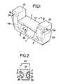
- Fig. 1 is an enlarged perspective view of a preferred embodiment of a V-shaped metal block for forming a power transmitting V-belt according to the present invention;
- Fig. 2 is a sectional view taken along a line II-II in Fig. 1;
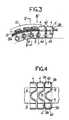
- Fig. 3 is a partially sectioned side view of the V-belt of this embodiment;
- Fig. 4 is a plan view of a portion of Fig. 3 seen in the direction of arrow IV;
- Fig. 5 is a sectional view taken along a line V-V in Fig. 3; and
- Fig. 6 shows one example of the prior art V-shaped metal block.
- A preferred embodiment of the present invention will now be described with reference to Figs. 1 to 5.
- As shown in Figs. 3 to 5, a metal band B is comprised of a plurality of endless laminated metal band elements Ba and has a bottom surface bearing on a
support surface 5a which forms a bottom surface of an upwardly openedrecessed groove 5 for receiving the metal band B in each of a large number of V-shaped metal blocks 4. Awire stopper member 6 is locked at its opposite ends in atransverse groove 9a and avertical groove 9b of a locking slot 9 to restrain and hold the metal band B.A roller member 7 is interposed between opposedsemi-cylindrical recesses 8 provided on the opposite side surfaces, as viewed in the lengthwise direction of the band B, of adjacent V-shaped metal blocks 4. Theroller member 7 may be cylindrical or at least provided with a pair of oppositely facing semi-cylindrical projections engaging the semi-cylindrical recesses. A V-belt 1 of this embodiment is comprised of the metal band B, a large number of the V-shaped metal blocks 4, a large number of theroller members 7 and a large number of thestopper members 6. - The V-
shaped metal block 4 according to this embodiment of the present invention is similar in basic structure to the prior art V-shaped metal block shown in Fig. 6 and has therecessed groove 5 between the oppositeupper walls inclined portions pulley 10. - Unlike the prior art shown in Fig. 6, however, a semi-cylindrical recess or
relief portion 8a having a certain axial width is provided at an axially central portion of each of thesemi-cylindrical recesses 8 of each of the V-shaped metal blocks 4. The relief portion has a radius R2 slightly larger than the radius R1 of the recess 8 (see Figs. 1 and 2). Therefore, therelief portion 8a is formed on themetal block 4 to be recessed more deeply than therecess 8. - In the operation of this embodiment of the invention, the provision of the
suitable relief portion 8a at the central portion of each of the pair ofrecesses 8 in the V-shaped metal block 4 makes it possible to compensate for any expansion of the metal at the central portion during sintering and thermal treatment due to the densification of the material whensuch metal block 4 is formed, for example, from a sintered alloy using complemental convex dies. Moreover, it is possible to prevent the generation of high surface pressure at the central portion due to an uneven contact with theroller member 7 and seizure due to failure of lubrication during use of the V-belt. - This construction permits the use of, for example, an iron-based sintered alloy as a material for such a block of a complicated shape which avoids the costly conventional machining otherwise required. In addition, the use of a sintered product previously impregnated with a lubricant in a so-called oilless (oil impregnated) bearing manner utilizing a porous structure, which is a characteristic thereof, can considerably improve the lubricity to reduce the frictional force and further contribute to prevention of a seizure or the like.
- The above effects can be likewise obtained not only with a V-belt of a type in which the
roller member 7 is locked in the respectiveopposed recesses adjacent metal blocks 4 as shown in the drawings, but also with a V-belt of a type in which one of the recesses is replaced by a projection, with the recess of one metal block being engaged by the projection of the adjacent metal block whereby the roller member is omitted.
Claims (5)
- A power transmitting V-belt comprising an endless metal band (B) mounted on a multiplicity of V-shaped metal blocks (4) lined to one another, with a semi-cylindrical recess (8) extending in a widthwise direction of said metal band (B) being provided on a V-shaped metal block (4) and engaged by a semi-cylindrical projection associated with an adjacent metal block (4) to provide a pivotable linkage between said adjacent V-shaped metal blocks, characterized in that a relief portion (8a) having a predetermined axial length is provided at an axially central portion of the said semi-cylindrical recess for minimizing the engagement between said semicylindrical recess (8) and said semicylindrical projection.
- A power transmitting V-belt according to claim 1, wherein each said V-shaped metal block (4) has said semi-cylindrical recess provided on each opposite side surface as viewed in the lengthwise direction of said metal band (B) and a roller member (7) is interposed between two adjacent V-shaped metal blocks (4) to be engaged in the respective opposed semi-cylindrical recesses (8) of said adjacent metal blocks (4).
- A power transmitting V-belt according to claim 2, wherein each of said roller members (7) is cylindrical.
- A power transmitting V-belt according to claims 1, 2 or 3, wherein said relief portion (8a) is formed into a semi-cylindrical shape having a radius (R2) larger than the radius (R1) of said semi-cylindrical recess (8).
- A power transmitting V-belt according to claims 1, 2 or 3, wherein said V-shaped metal block (4) is formed from a sintered alloy.
Applications Claiming Priority (2)
| Application Number | Priority Date | Filing Date | Title |
|---|---|---|---|
| JP86771/87 | 1987-06-05 | ||
| JP1987086771UJPS63195143U (en) | 1987-06-05 | 1987-06-05 |
Publications (2)
| Publication Number | Publication Date |
|---|---|
| EP0296397A1 EP0296397A1 (en) | 1988-12-28 |
| EP0296397B1true EP0296397B1 (en) | 1991-08-14 |
Family
ID=13896013
Family Applications (1)
| Application Number | Title | Priority Date | Filing Date |
|---|---|---|---|
| EP88108943AExpiredEP0296397B1 (en) | 1987-06-05 | 1988-06-03 | Power transmitting v-belt |
Country Status (4)
| Country | Link |
|---|---|
| US (1) | US4854926A (en) |
| EP (1) | EP0296397B1 (en) |
| JP (1) | JPS63195143U (en) |
| DE (1) | DE3864205D1 (en) |
Families Citing this family (9)
| Publication number | Priority date | Publication date | Assignee | Title |
|---|---|---|---|---|
| CA2047048C (en)* | 1990-07-25 | 1996-07-30 | Takashi Masuda | High load force transmission belt |
| JPH0738749Y2 (en)* | 1991-04-25 | 1995-09-06 | 有限会社マツオエンジニアリング | Drive belt for continuously variable transmission |
| DE60005746T2 (en)* | 1999-06-18 | 2004-04-29 | Honda Giken Kogyo K.K. | Belt for continuously variable transmission |
| CN102906452B (en)* | 2011-05-27 | 2015-05-20 | 丰田自动车株式会社 | Drive belt and assembly method for drive belt |
| JP5840293B2 (en)* | 2012-07-06 | 2016-01-06 | 本田技研工業株式会社 | Metal belt element |
| CN109073043B (en)* | 2016-05-18 | 2020-12-15 | 爱信艾达株式会社 | Transmission belt |
| JP6711956B2 (en)* | 2017-03-03 | 2020-06-17 | アイシン・エィ・ダブリュ株式会社 | Element design method and transmission belt |
| JP6809368B2 (en)* | 2017-05-16 | 2021-01-06 | アイシン・エィ・ダブリュ株式会社 | Continuously variable transmission and transmission belt |
| JP6621495B2 (en)* | 2018-04-03 | 2019-12-18 | 本田技研工業株式会社 | Metal element for continuously variable transmission and method for manufacturing metal element for continuously variable transmission |
Family Cites Families (4)
| Publication number | Priority date | Publication date | Assignee | Title |
|---|---|---|---|---|
| JPS6079038U (en)* | 1983-11-07 | 1985-06-01 | 本田技研工業株式会社 | V-belt transmission device |
| JPS61266844A (en)* | 1985-05-18 | 1986-11-26 | Honda Motor Co Ltd | Laminated metal belt for torque transmission |
| US4741727A (en)* | 1985-12-23 | 1988-05-03 | Honda Giken Kogyo Kabushiki Kaisha | Power transmission V belt |
| US4758211A (en)* | 1985-12-25 | 1988-07-19 | Honda Giken Kogyo Kabushiki Kaisha | V belt for power transmission |
- 1987
- 1987-06-05JPJP1987086771Upatent/JPS63195143U/jaactivePending
- 1988
- 1988-06-03DEDE8888108943Tpatent/DE3864205D1/ennot_activeExpired - Lifetime
- 1988-06-03EPEP88108943Apatent/EP0296397B1/ennot_activeExpired
- 1988-06-06USUS07/203,001patent/US4854926A/ennot_activeExpired - Fee Related
Also Published As
| Publication number | Publication date |
|---|---|
| US4854926A (en) | 1989-08-08 |
| JPS63195143U (en) | 1988-12-15 |
| DE3864205D1 (en) | 1991-09-19 |
| EP0296397A1 (en) | 1988-12-28 |
Similar Documents
| Publication | Publication Date | Title |
|---|---|---|
| EP0296397B1 (en) | Power transmitting v-belt | |
| US4281483A (en) | Method of curving supporting surfaces of driving belt elements | |
| AU641260B2 (en) | High load force transmission belt | |
| EP1132649B1 (en) | Metal belt element | |
| US5597243A (en) | Radial rolling bearing | |
| US3636792A (en) | Hertzian stress-reducing means for gears | |
| US6206575B1 (en) | Cage for bearing and bearing using the same | |
| GB2372078A (en) | Half bearing with grooves preventing leakage of lubricating oil | |
| US4498892A (en) | Power transmission belt | |
| US4642079A (en) | Transmission chain | |
| GB2117065A (en) | A one-way clutch | |
| US6045474A (en) | Drive belt, element therefor and construction in which this is used | |
| JPS6317879Y2 (en) | ||
| US6540404B1 (en) | Sintered plain bearing for engines and gears | |
| US4741727A (en) | Power transmission V belt | |
| EP0994275A1 (en) | Drive belt, element therefor and construction in which this is used | |
| EP1371876A2 (en) | Belt for continuously variable transmission | |
| US4629340A (en) | Roller bearing assembly | |
| US5788594A (en) | Low noise belt for continuously variable transmission | |
| EP0588416A1 (en) | Transverse element for an endless transmission unit | |
| JP3146386B2 (en) | Roller bearing cage | |
| EP0510990B1 (en) | Driving belt for stepless speed variation | |
| GB2040367A (en) | Improvements in the physical characteristics of a pair of sliding elements | |
| JPS638330B2 (en) | ||
| US5004359A (en) | Roller bearing |
Legal Events
| Date | Code | Title | Description |
|---|---|---|---|
| PUAI | Public reference made under article 153(3) epc to a published international application that has entered the european phase | Free format text:ORIGINAL CODE: 0009012 | |
| AK | Designated contracting states | Kind code of ref document:A1 Designated state(s):DE FR GB IT | |
| 17P | Request for examination filed | Effective date:19890110 | |
| 17Q | First examination report despatched | Effective date:19891218 | |
| GRAA | (expected) grant | Free format text:ORIGINAL CODE: 0009210 | |
| AK | Designated contracting states | Kind code of ref document:B1 Designated state(s):DE FR GB IT | |
| PG25 | Lapsed in a contracting state [announced via postgrant information from national office to epo] | Ref country code:IT Free format text:LAPSE BECAUSE OF FAILURE TO SUBMIT A TRANSLATION OF THE DESCRIPTION OR TO PAY THE FEE WITHIN THE PRE;WARNING: LAPSES OF ITALIAN PATENTS WITH EFFECTIVE DATE BEFORE 2007 MAY HAVE OCCURRED AT ANY TIME BEFORE 2007. THE CORRECT EFFECTIVE DATE MAY BE DIFFERENT FROM THE ONE RECORDED.SCRIBED TIME-LIMIT Effective date:19910814 Ref country code:FR Effective date:19910814 | |
| REF | Corresponds to: | Ref document number:3864205 Country of ref document:DE Date of ref document:19910919 | |
| EN | Fr: translation not filed | ||
| PG25 | Lapsed in a contracting state [announced via postgrant information from national office to epo] | Ref country code:GB Effective date:19920603 | |
| PLBE | No opposition filed within time limit | Free format text:ORIGINAL CODE: 0009261 | |
| STAA | Information on the status of an ep patent application or granted ep patent | Free format text:STATUS: NO OPPOSITION FILED WITHIN TIME LIMIT | |
| 26N | No opposition filed | ||
| GBPC | Gb: european patent ceased through non-payment of renewal fee | Effective date:19920603 | |
| PGFP | Annual fee paid to national office [announced via postgrant information from national office to epo] | Ref country code:DE Payment date:19940630 Year of fee payment:7 | |
| PG25 | Lapsed in a contracting state [announced via postgrant information from national office to epo] | Ref country code:DE Effective date:19960301 |