EP0295200B1 - Endoprosthesis - Google Patents
EndoprosthesisDownload PDFInfo
- Publication number
- EP0295200B1 EP0295200B1EP88730134AEP88730134AEP0295200B1EP 0295200 B1EP0295200 B1EP 0295200B1EP 88730134 AEP88730134 AEP 88730134AEP 88730134 AEP88730134 AEP 88730134AEP 0295200 B1EP0295200 B1EP 0295200B1
- Authority
- EP
- European Patent Office
- Prior art keywords
- prosthesis
- blades
- endoprosthesis according
- shank
- endoprosthesis
- Prior art date
- Legal status (The legal status is an assumption and is not a legal conclusion. Google has not performed a legal analysis and makes no representation as to the accuracy of the status listed.)
- Expired - Lifetime
Links
- 210000000988bone and boneAnatomy0.000claimsdescription45
- 210000002303tibiaAnatomy0.000claimsdescription21
- 238000005520cutting processMethods0.000claimsdescription20
- 210000000689upper legAnatomy0.000claimsdescription17
- 239000000463materialSubstances0.000claimsdescription11
- 230000002093peripheral effectEffects0.000claimsdescription9
- RTAQQCXQSZGOHL-UHFFFAOYSA-NTitaniumChemical compound[Ti]RTAQQCXQSZGOHL-UHFFFAOYSA-N0.000claimsdescription2
- 239000004568cementSubstances0.000claimsdescription2
- 239000010936titaniumSubstances0.000claimsdescription2
- 229910052719titaniumInorganic materials0.000claimsdescription2
- 210000001699lower legAnatomy0.000claims9
- 238000010276constructionMethods0.000claims1
- 241000446313LamellaSpecies0.000description41
- 230000006978adaptationEffects0.000description7
- 210000000629knee jointAnatomy0.000description6
- 210000002436femur neckAnatomy0.000description5
- 238000001356surgical procedureMethods0.000description5
- 230000005540biological transmissionEffects0.000description4
- 230000006378damageEffects0.000description4
- 238000006073displacement reactionMethods0.000description4
- 230000035479physiological effects, processes and functionsEffects0.000description4
- 238000004873anchoringMethods0.000description3
- 238000011161developmentMethods0.000description3
- 230000018109developmental processEffects0.000description3
- 210000004394hip jointAnatomy0.000description3
- 229910052751metalInorganic materials0.000description3
- 239000002184metalSubstances0.000description3
- 239000000126substanceSubstances0.000description3
- 210000003484anatomyAnatomy0.000description2
- 210000001264anterior cruciate ligamentAnatomy0.000description2
- 210000001185bone marrowAnatomy0.000description2
- 230000001054cortical effectEffects0.000description2
- 238000009826distributionMethods0.000description2
- 230000002349favourable effectEffects0.000description2
- 239000007943implantSubstances0.000description2
- 238000002513implantationMethods0.000description2
- 208000015181infectious diseaseDiseases0.000description2
- 210000003127kneeAnatomy0.000description2
- ORQBXQOJMQIAOY-UHFFFAOYSA-NnobeliumChemical compound[No]ORQBXQOJMQIAOY-UHFFFAOYSA-N0.000description2
- 210000004417patellaAnatomy0.000description2
- 238000004321preservationMethods0.000description2
- 238000002271resectionMethods0.000description2
- 230000035882stressEffects0.000description2
- 206010003694AtrophyDiseases0.000description1
- 239000004698PolyethyleneSubstances0.000description1
- 238000010521absorption reactionMethods0.000description1
- 230000032683agingEffects0.000description1
- 230000037444atrophyEffects0.000description1
- 238000005452bendingMethods0.000description1
- 239000000560biocompatible materialSubstances0.000description1
- 230000015572biosynthetic processEffects0.000description1
- 230000017531blood circulationEffects0.000description1
- 239000002639bone cementSubstances0.000description1
- 238000000576coating methodMethods0.000description1
- 230000007547defectEffects0.000description1
- 208000037265diseases, disorders, signs and symptomsDiseases0.000description1
- 208000035475disorderDiseases0.000description1
- 210000002082fibulaAnatomy0.000description1
- 210000001624hipAnatomy0.000description1
- 210000003041ligamentAnatomy0.000description1
- 238000004519manufacturing processMethods0.000description1
- 230000002503metabolic effectEffects0.000description1
- 238000000034methodMethods0.000description1
- 239000000203mixtureSubstances0.000description1
- 229920003023plasticPolymers0.000description1
- 239000004033plasticSubstances0.000description1
- -1polyethylenePolymers0.000description1
- 229920000573polyethylenePolymers0.000description1
- 230000002028prematureEffects0.000description1
- 238000005096rolling processMethods0.000description1
- 238000010079rubber tappingMethods0.000description1
- 239000007787solidSubstances0.000description1
- 230000005477standard modelEffects0.000description1
- 238000004018waxingMethods0.000description1
Images


Classifications
- A—HUMAN NECESSITIES
- A61—MEDICAL OR VETERINARY SCIENCE; HYGIENE
- A61F—FILTERS IMPLANTABLE INTO BLOOD VESSELS; PROSTHESES; DEVICES PROVIDING PATENCY TO, OR PREVENTING COLLAPSING OF, TUBULAR STRUCTURES OF THE BODY, e.g. STENTS; ORTHOPAEDIC, NURSING OR CONTRACEPTIVE DEVICES; FOMENTATION; TREATMENT OR PROTECTION OF EYES OR EARS; BANDAGES, DRESSINGS OR ABSORBENT PADS; FIRST-AID KITS
- A61F2/00—Filters implantable into blood vessels; Prostheses, i.e. artificial substitutes or replacements for parts of the body; Appliances for connecting them with the body; Devices providing patency to, or preventing collapsing of, tubular structures of the body, e.g. stents
- A61F2/02—Prostheses implantable into the body
- A61F2/30—Joints
- A61F2/38—Joints for elbows or knees
- A61F2/389—Tibial components
- A—HUMAN NECESSITIES
- A61—MEDICAL OR VETERINARY SCIENCE; HYGIENE
- A61F—FILTERS IMPLANTABLE INTO BLOOD VESSELS; PROSTHESES; DEVICES PROVIDING PATENCY TO, OR PREVENTING COLLAPSING OF, TUBULAR STRUCTURES OF THE BODY, e.g. STENTS; ORTHOPAEDIC, NURSING OR CONTRACEPTIVE DEVICES; FOMENTATION; TREATMENT OR PROTECTION OF EYES OR EARS; BANDAGES, DRESSINGS OR ABSORBENT PADS; FIRST-AID KITS
- A61F2/00—Filters implantable into blood vessels; Prostheses, i.e. artificial substitutes or replacements for parts of the body; Appliances for connecting them with the body; Devices providing patency to, or preventing collapsing of, tubular structures of the body, e.g. stents
- A61F2/02—Prostheses implantable into the body
- A61F2/30—Joints
- A61F2/32—Joints for the hip
- A61F2/36—Femoral heads ; Femoral endoprostheses
- A61F2/3662—Femoral shafts
- A—HUMAN NECESSITIES
- A61—MEDICAL OR VETERINARY SCIENCE; HYGIENE
- A61F—FILTERS IMPLANTABLE INTO BLOOD VESSELS; PROSTHESES; DEVICES PROVIDING PATENCY TO, OR PREVENTING COLLAPSING OF, TUBULAR STRUCTURES OF THE BODY, e.g. STENTS; ORTHOPAEDIC, NURSING OR CONTRACEPTIVE DEVICES; FOMENTATION; TREATMENT OR PROTECTION OF EYES OR EARS; BANDAGES, DRESSINGS OR ABSORBENT PADS; FIRST-AID KITS
- A61F2/00—Filters implantable into blood vessels; Prostheses, i.e. artificial substitutes or replacements for parts of the body; Appliances for connecting them with the body; Devices providing patency to, or preventing collapsing of, tubular structures of the body, e.g. stents
- A61F2/02—Prostheses implantable into the body
- A61F2/30—Joints
- A61F2002/30001—Additional features of subject-matter classified in A61F2/28, A61F2/30 and subgroups thereof
- A61F2002/30108—Shapes
- A61F2002/3011—Cross-sections or two-dimensional shapes
- A61F2002/30112—Rounded shapes, e.g. with rounded corners
- A61F2002/30131—Rounded shapes, e.g. with rounded corners horseshoe- or crescent- or C-shaped or U-shaped
- A—HUMAN NECESSITIES
- A61—MEDICAL OR VETERINARY SCIENCE; HYGIENE
- A61F—FILTERS IMPLANTABLE INTO BLOOD VESSELS; PROSTHESES; DEVICES PROVIDING PATENCY TO, OR PREVENTING COLLAPSING OF, TUBULAR STRUCTURES OF THE BODY, e.g. STENTS; ORTHOPAEDIC, NURSING OR CONTRACEPTIVE DEVICES; FOMENTATION; TREATMENT OR PROTECTION OF EYES OR EARS; BANDAGES, DRESSINGS OR ABSORBENT PADS; FIRST-AID KITS
- A61F2/00—Filters implantable into blood vessels; Prostheses, i.e. artificial substitutes or replacements for parts of the body; Appliances for connecting them with the body; Devices providing patency to, or preventing collapsing of, tubular structures of the body, e.g. stents
- A61F2/02—Prostheses implantable into the body
- A61F2/30—Joints
- A61F2002/30001—Additional features of subject-matter classified in A61F2/28, A61F2/30 and subgroups thereof
- A61F2002/30316—The prosthesis having different structural features at different locations within the same prosthesis; Connections between prosthetic parts; Special structural features of bone or joint prostheses not otherwise provided for
- A61F2002/30535—Special structural features of bone or joint prostheses not otherwise provided for
- A61F2002/30593—Special structural features of bone or joint prostheses not otherwise provided for hollow
- A—HUMAN NECESSITIES
- A61—MEDICAL OR VETERINARY SCIENCE; HYGIENE
- A61F—FILTERS IMPLANTABLE INTO BLOOD VESSELS; PROSTHESES; DEVICES PROVIDING PATENCY TO, OR PREVENTING COLLAPSING OF, TUBULAR STRUCTURES OF THE BODY, e.g. STENTS; ORTHOPAEDIC, NURSING OR CONTRACEPTIVE DEVICES; FOMENTATION; TREATMENT OR PROTECTION OF EYES OR EARS; BANDAGES, DRESSINGS OR ABSORBENT PADS; FIRST-AID KITS
- A61F2/00—Filters implantable into blood vessels; Prostheses, i.e. artificial substitutes or replacements for parts of the body; Appliances for connecting them with the body; Devices providing patency to, or preventing collapsing of, tubular structures of the body, e.g. stents
- A61F2/02—Prostheses implantable into the body
- A61F2/30—Joints
- A61F2/30767—Special external or bone-contacting surface, e.g. coating for improving bone ingrowth
- A61F2/30771—Special external or bone-contacting surface, e.g. coating for improving bone ingrowth applied in original prostheses, e.g. holes or grooves
- A61F2002/30772—Apertures or holes, e.g. of circular cross section
- A61F2002/30784—Plurality of holes
- A61F2002/30785—Plurality of holes parallel
- A—HUMAN NECESSITIES
- A61—MEDICAL OR VETERINARY SCIENCE; HYGIENE
- A61F—FILTERS IMPLANTABLE INTO BLOOD VESSELS; PROSTHESES; DEVICES PROVIDING PATENCY TO, OR PREVENTING COLLAPSING OF, TUBULAR STRUCTURES OF THE BODY, e.g. STENTS; ORTHOPAEDIC, NURSING OR CONTRACEPTIVE DEVICES; FOMENTATION; TREATMENT OR PROTECTION OF EYES OR EARS; BANDAGES, DRESSINGS OR ABSORBENT PADS; FIRST-AID KITS
- A61F2/00—Filters implantable into blood vessels; Prostheses, i.e. artificial substitutes or replacements for parts of the body; Appliances for connecting them with the body; Devices providing patency to, or preventing collapsing of, tubular structures of the body, e.g. stents
- A61F2/02—Prostheses implantable into the body
- A61F2/30—Joints
- A61F2/30767—Special external or bone-contacting surface, e.g. coating for improving bone ingrowth
- A61F2/30771—Special external or bone-contacting surface, e.g. coating for improving bone ingrowth applied in original prostheses, e.g. holes or grooves
- A61F2002/30772—Apertures or holes, e.g. of circular cross section
- A61F2002/30784—Plurality of holes
- A61F2002/30789—Plurality of holes perpendicular with respect to each other
- A—HUMAN NECESSITIES
- A61—MEDICAL OR VETERINARY SCIENCE; HYGIENE
- A61F—FILTERS IMPLANTABLE INTO BLOOD VESSELS; PROSTHESES; DEVICES PROVIDING PATENCY TO, OR PREVENTING COLLAPSING OF, TUBULAR STRUCTURES OF THE BODY, e.g. STENTS; ORTHOPAEDIC, NURSING OR CONTRACEPTIVE DEVICES; FOMENTATION; TREATMENT OR PROTECTION OF EYES OR EARS; BANDAGES, DRESSINGS OR ABSORBENT PADS; FIRST-AID KITS
- A61F2/00—Filters implantable into blood vessels; Prostheses, i.e. artificial substitutes or replacements for parts of the body; Appliances for connecting them with the body; Devices providing patency to, or preventing collapsing of, tubular structures of the body, e.g. stents
- A61F2/02—Prostheses implantable into the body
- A61F2/30—Joints
- A61F2/30767—Special external or bone-contacting surface, e.g. coating for improving bone ingrowth
- A61F2/30771—Special external or bone-contacting surface, e.g. coating for improving bone ingrowth applied in original prostheses, e.g. holes or grooves
- A61F2002/30841—Sharp anchoring protrusions for impaction into the bone, e.g. sharp pins, spikes
- A61F2002/30845—Sharp anchoring protrusions for impaction into the bone, e.g. sharp pins, spikes with cutting edges
- A—HUMAN NECESSITIES
- A61—MEDICAL OR VETERINARY SCIENCE; HYGIENE
- A61F—FILTERS IMPLANTABLE INTO BLOOD VESSELS; PROSTHESES; DEVICES PROVIDING PATENCY TO, OR PREVENTING COLLAPSING OF, TUBULAR STRUCTURES OF THE BODY, e.g. STENTS; ORTHOPAEDIC, NURSING OR CONTRACEPTIVE DEVICES; FOMENTATION; TREATMENT OR PROTECTION OF EYES OR EARS; BANDAGES, DRESSINGS OR ABSORBENT PADS; FIRST-AID KITS
- A61F2/00—Filters implantable into blood vessels; Prostheses, i.e. artificial substitutes or replacements for parts of the body; Appliances for connecting them with the body; Devices providing patency to, or preventing collapsing of, tubular structures of the body, e.g. stents
- A61F2/02—Prostheses implantable into the body
- A61F2/30—Joints
- A61F2/32—Joints for the hip
- A61F2/36—Femoral heads ; Femoral endoprostheses
- A61F2/3609—Femoral heads or necks; Connections of endoprosthetic heads or necks to endoprosthetic femoral shafts
- A61F2002/3625—Necks
- A61F2002/3631—Necks with an integral complete or partial peripheral collar or bearing shoulder at its base
- A—HUMAN NECESSITIES
- A61—MEDICAL OR VETERINARY SCIENCE; HYGIENE
- A61F—FILTERS IMPLANTABLE INTO BLOOD VESSELS; PROSTHESES; DEVICES PROVIDING PATENCY TO, OR PREVENTING COLLAPSING OF, TUBULAR STRUCTURES OF THE BODY, e.g. STENTS; ORTHOPAEDIC, NURSING OR CONTRACEPTIVE DEVICES; FOMENTATION; TREATMENT OR PROTECTION OF EYES OR EARS; BANDAGES, DRESSINGS OR ABSORBENT PADS; FIRST-AID KITS
- A61F2/00—Filters implantable into blood vessels; Prostheses, i.e. artificial substitutes or replacements for parts of the body; Appliances for connecting them with the body; Devices providing patency to, or preventing collapsing of, tubular structures of the body, e.g. stents
- A61F2/02—Prostheses implantable into the body
- A61F2/30—Joints
- A61F2/32—Joints for the hip
- A61F2/36—Femoral heads ; Femoral endoprostheses
- A61F2/3662—Femoral shafts
- A61F2002/3678—Geometrical features
- A61F2002/368—Geometrical features with lateral apertures, bores, holes or openings, e.g. for reducing the mass, for receiving fixation screws or for communicating with the inside of a hollow shaft
- A—HUMAN NECESSITIES
- A61—MEDICAL OR VETERINARY SCIENCE; HYGIENE
- A61F—FILTERS IMPLANTABLE INTO BLOOD VESSELS; PROSTHESES; DEVICES PROVIDING PATENCY TO, OR PREVENTING COLLAPSING OF, TUBULAR STRUCTURES OF THE BODY, e.g. STENTS; ORTHOPAEDIC, NURSING OR CONTRACEPTIVE DEVICES; FOMENTATION; TREATMENT OR PROTECTION OF EYES OR EARS; BANDAGES, DRESSINGS OR ABSORBENT PADS; FIRST-AID KITS
- A61F2/00—Filters implantable into blood vessels; Prostheses, i.e. artificial substitutes or replacements for parts of the body; Appliances for connecting them with the body; Devices providing patency to, or preventing collapsing of, tubular structures of the body, e.g. stents
- A61F2/02—Prostheses implantable into the body
- A61F2/30—Joints
- A61F2/32—Joints for the hip
- A61F2/36—Femoral heads ; Femoral endoprostheses
- A61F2/3662—Femoral shafts
- A61F2002/3678—Geometrical features
- A61F2002/369—Stepped shaft, i.e. having discrete diameter changes
- A—HUMAN NECESSITIES
- A61—MEDICAL OR VETERINARY SCIENCE; HYGIENE
- A61F—FILTERS IMPLANTABLE INTO BLOOD VESSELS; PROSTHESES; DEVICES PROVIDING PATENCY TO, OR PREVENTING COLLAPSING OF, TUBULAR STRUCTURES OF THE BODY, e.g. STENTS; ORTHOPAEDIC, NURSING OR CONTRACEPTIVE DEVICES; FOMENTATION; TREATMENT OR PROTECTION OF EYES OR EARS; BANDAGES, DRESSINGS OR ABSORBENT PADS; FIRST-AID KITS
- A61F2230/00—Geometry of prostheses classified in groups A61F2/00 - A61F2/26 or A61F2/82 or A61F9/00 or A61F11/00 or subgroups thereof
- A61F2230/0002—Two-dimensional shapes, e.g. cross-sections
- A61F2230/0004—Rounded shapes, e.g. with rounded corners
- A61F2230/0013—Horseshoe-shaped, e.g. crescent-shaped, C-shaped, U-shaped
Definitions
- the inventionrelates to an endoprosthesis of the type specified in the preamble of claim 1.
- Hip endoprosthesesconsist of a prosthesis head, a prosthesis collar and a prosthesis socket which is anchored in the medullary cavity of the patient's femur using bone cement or without cement.
- a stem structureis used which ensures anchoring as firmly as possible in the medullary canal, whereby a porous surface should facilitate the ingrowth of spongy material and thus increase the strength of the anchoring of the prosthesis socket.
- a solid, one-piece, drivable hip joint prosthesis known from EP-A-0181586has at the proximal end a plurality of ribs which extend outwards from the shaft core and whose back surfaces are serrated. The individual ribs are aligned in such a way that they are at right angles or at an angle to one another.
- a disadvantage of this known hip joint prosthesisis that the amount of material to be hammered into the body is not small and that a not inconsiderable amount of cancellous bone must be removed before the endoprosthesis is inserted.
- Another drive-in hip joint endoprosthesis known from US-A-4287617, but not provided with cutting edges,has a prosthesis shaft, which has a Cross-section has an open contour and consists of a plurality of plate-shaped lamellae which extend in the driving direction of the endoprosthesis.
- a prosthesis shaftwhich has a Cross-section has an open contour and consists of a plurality of plate-shaped lamellae which extend in the driving direction of the endoprosthesis.
- To anchor this prosthesis socket in the medullary canalextensive removal of the cancellous bone of the intertrochanteric region is also necessary.
- the removal of the cancellous boneis to be regarded as an unphysiological local disorder in the sense of a defect formation, since this impairs the stress and, above all, age-related adaptation options.
- Another disadvantage of known endoprosthesesis an uneven distribution of force due to a primarily distal introduction of the forces into the thigh portion located distal to the intertrochanteric region, as a result of which the bone portion actually intended for this is removed from the functional load. This leads to atrophy and not to the desired functional stimulus for the bone to grow fixatively to the endoprosthesis.
- Another disadvantage of known endoprosthesesis that there are standard models for different femur sizes, but they are not adapted to the individual shape of the proximal femur of a patient, so that the unfavorable application of force to many endoprostheses is intensified and the existing bone substance is not used optimally.
- the known endoprosthesesrequire a complex surgical technique, in which it is necessary to pre-chisel or pre-drill the bone to be provided with the prosthesis to receive the prosthesis shaft. This must be done with great caution, since neither the bone structure should be damaged unnecessarily nor an excessively large cavity may be created in which the prosthesis socket cannot be sufficiently firmly anchored. In addition, a considerable amount of time is required for rasping or boring, which increases the risk of infection considerably. The opening of the medullary canal is also necessary and there is a considerable risk of destruction of the bone as a result of a via falsa.
- the inventionhas for its object to provide an endoprosthesis of the type mentioned that the preservation of the physiology of the bone marrow space including the intertrochanteric cancellous bone and thus favorable anatomical Conditions for revision surgery and optimal adaptation options to age-related bone changes, a simplified surgical technique without the need to chisel or pre-drill and optimal physiological force transmission as well as an enlarged contact surface for the growth of bone material and individual adaptation to the shape of the patient's femur.
- This objectis achieved with the characterizing feature of claim 1.
- the solution according to the inventionenables the attachment of an endoprosthesis while preserving the cancellous structures, so that the metabolic biology is not disturbed and the conditions of the blood circulation are not fundamentally changed.
- the endoprosthesis according to the inventionenables secure anchoring of the lamellae provided with cutting edges running along their periphery, so that the stepped lamellae of the endoprosthesis to be driven into the cancellous bone are self-tapping and do not require pre-cutting or rasping.
- An essential prerequisite for driving in the prosthesis shaftis that all of the partial surfaces of the endoprosthesis system to be driven in are arranged in parallel and to be driven in parallel to the axis of the thigh shaft, that is to say driven in perpendicular to the cross section, without additional preparatory work being necessary.
- the number and the cross-sectional shape of the plate-shaped lamellaecan be arbitrary, on the one hand an enlarged contact surface for the growth of bone material and on the other hand the prerequisite for an individual adaptability of the endoprosthesis to the respective bone shape is made possible with little means.
- the solution according to the inventionis based on the finding that a coarsely permeable foreign body is introduced as the fixation part, the sponiosa being cut apart only once when driven in, so that it can then be adapted again exactly with the majority of the cut surface.
- the intertrochanteric lamellar prosthesis according to the inventionenables a secure seat by placing the prosthetic collar flat on the cortical bone of the resection incision on the neck of the femur and the cancellous structure here. It is irrelevant whether a horizontal or an oblique cut is selected for the operation.
- a further advantageous embodiment of the solution according to the inventionis characterized in that the lamellae and / or the connecting lamellae and / or the extension webs have bores and / or openings. This creates additional space for the ingrowth of cancellous material, so that on the one hand the complex toothed cancellous bone structure is used to transmit the forces that occur and on the other hand an optimal connection of the endoprosthesis to the bone is ensured so that loosening is not to be feared or only to a small extent .
- Another advantageous development of the inventionrelates to a prosthesis of the type mentioned in the form of a tibial plateau prosthesis.
- Such a prosthesisis known from DE-OS 34 29 157 as a cementless implantable tibial plateau implant, which consists of a metal plate and a plastic slide bearing attached thereon and an inlet plate which is essentially vertical on the side facing away from the slide bearing on the metal plate attached to the metal plate.
- the inlet plateessentially serves to prevent the tibial plateau from tipping over and / or shifting even when the knee joint is in a loaded flexion position, despite the cementless implantation.
- a bone screwis screwed through the inlet plate into the tibia head, which, however, makes it difficult to attach the tibia plateau and, moreover, represents an additional load on the tibia.
- Such a tibial plateau prosthesisshould be easily attachable and connectable to the shin in a manner that prevents it from shifting and tilting.
- the solution according to this developmentmakes it possible to attach a tibial plateau in the dorsal-ventral direction and thereby ensure that the tibial plateau is secured against displacement and tilting. Since the tibial plateau prosthesis according to the invention is inserted ventrally and driven into the tibia in the dorsal direction, it is only necessary to shift the anterior knee ligaments laterally.
- the large surfaces formed by the plates in the transverse directionprevent the tibial plateau from tipping over, even in the event of a knee flexion load associated with it Action of a bending moment on the prosthesis, which, in known tibial plateaus, leads to the tibial plateau being released from its anterior connection to the bone bearing due to the tensile stress acting on the anterior plateau region.
- the lower edges of the plate-shaped lamellae opposite the tibia plateauare connected to one another via one or more plate-shaped connecting lamellae, so that the lamellae form a U-shaped or dovetail-shaped fastening element with the connecting lamellae.
- the front edges of the lamellae or of the connecting lamellaare designed in a cutting shape, which facilitates driving the fastening element into the tibia and leads to the least possible damage to the tibia.
- Additional perforations provided in the lamellae and connecting lamellaeallow bone tissue to grow into the perforations and thus additionally stabilize the tibial plateau.
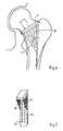
- FIG. 1 to 3show an intertrochanteric lamella prosthesis in perspective view, in cross section and in side view, the side view being drawn schematically into a femur in order to clarify the position and the shape of the endoprosthesis adapted to the shape of the bone.
- the lamella prosthesisconsists of a prosthesis shaft 1, a prosthesis collar 2 and a conical pin 3 for receiving a prosthesis head, not shown.
- the prosthesis socket 1has two parallel surfaces arranged as plate-shaped partial surfaces Slats 10, 11, 12, the peripheral edges of which are designed as cutting edges 5.
- One of the cutting edges 5 of the lamellae 10, 11is arch-shaped and thus simulates the outer shape of the femur.
- the lamella 11is connected to an extension web 40, wherein the connection can be made in one piece.
- the extension web 40is also provided with a lower cutting edge 5.
- the two lamellae 10, 11 arranged parallel to one anotherare connected to one another via a connecting lamella 31, which likewise has a cutting edge 5 on its underside.
- the lamellae 10, 11, 12 and the extension web 40are provided with bores 60 into which cancellous material can grow.
- the cross-sectionally U-shaped lamella prosthesis shown in FIGS. 1 to 3is characterized by a large surface area for the growth and ingrowth of cancellous material and by an optimal shape adapted to the shape of the bone. Due to the parallel in the longitudinal direction of the prosthesis shaft 1, the lamellae 10, 11, 12, the connecting lamella 31 and the extension web 40, the lamella prosthesis can be inserted or hammered in perpendicularly to the axis of the femur without having to chisel or predrill.
- the cutting edges 5make it easier to drive in the intertrochanteric lamella prosthesis. In this way the normal physiology of the bone is fully preserved and sufficient bone substance is still available in the event of a revision operation that may become necessary, the resection of the endoprosthesis in a revision operation being carried out without significant damage to the bone because of the parallel partial surfaces.
- FIGS. 1 to 3The open structuring of the endoprosthesis shown in FIGS. 1 to 3 creates the prerequisite for the prosthesis to be able to grow through with spongiosa through and through, which prevents the prosthesis from loosening even under heavy and changing loads.
- the lamellar structure of the prosthesisnot only enables individual adaptation of the prosthesis to the respective anatomy of the bone using simple technical means, since only plate-shaped partial surfaces can be machined, but also creates the conditions for the lamellae and / or connecting lamellae and / or extension bars can be shaped in such a way that, taking into account the respective anatomy of the bone, optimal force transmission and even force distribution can take place without pressure concentrations.
- the surface structurecan be further improved by additionally using a biocompatible material with microporosity for the lamellae and connecting webs, so that the firmness of the fit of the endoprosthesis in the bone is increased.
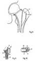
- FIGS. 4 and 5show a variant of the intertrochanteric lamella prosthesis, which consists of two main lamellae 13, 14 arranged parallel to one another and a lamella 15 connecting the parallel main lamellae 13, 14.
- the two main fins 13, 14are connected to one another by connecting fins 32 to 35, which contribute to increasing the surface area.
- the lamellaehave peripheral cutting edges 5.
- the main lamellae 13, 14, 15 and possibly the connecting lamellae 32 to 35are provided with openings 61 which allow the growth of spongy material.
- this prosthesis shapeis optimally adapted to the shape of the bone, so that a maximum surface area is used.
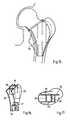
- FIGS. 6 and 7show an intertrochanteric lamella prosthesis with a plate-shaped main lamella 16 which is connected to the prosthesis collar 2 via two triangular lamellae 17, 18.
- the main lamella 16is tapered at its distal end and has openings 63, which in this embodiment are rectangular.
- the openings 62 provided in the triangular side plates 17, 18are adapted to the outer shape of the side plates 17, 18.
- the side view according to FIG. 6illustrates the lower cutting edge of the main lamella 16, which enables the intertrochanteric lamella prosthesis to be easily driven into the femur.
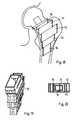
- FIGS. 8 to 10show a variant of the intertrochanteric lamella prosthesis according to FIGS. 6 and 7.
- This prosthesisalso consists of a main lamella 19 with openings 63 and laterally attached side lamellae 20, 21, the peripheral cutting edges of which are designed to be curved to match the shape of the bone.
- an extension web 41is attached centrally to the main lamella 19 and is connected at right angles to an extension plate 42, so that a T-shaped extension is provided.
- the peripheral edgesare designed as cutting edges.
- FIGS. 11 and 12show a side view or a perspective view of an intertrochanteric lamella prosthesis with a main lamella 22, which is connected approximately at right angles to an upper cover surface 70, against which the prosthesis collar 2 with the conically shaped pin 3 for receiving the prosthesis head connects.
- a lamella 23is placed centrally on the main lamella 22, the outer edges of which are connected to the top surface 70 and the prosthesis collar 2.
- the lower peripheral edge of the lamella 23, like the lower edge of the main lamella 22,is designed as a cutting edge.
- FIGS. 13 and 14show a box-shaped or funnel-shaped intertrochanteric lamella prosthesis in side view or in perspective view. It consists of mutually parallel slats 24, 25 and the two slats 24, 25 interconnecting, parallel Slats 26, 27, 28 aligned with the longitudinal direction of the prosthesis shaft.
- the respective peripheral edges of the slats 24 to 28are designed as cutting edges and provided with openings 65 which are adapted to the outer geometry of the slats.
- FIGS. 15 to 17show, in side view, perspective view and in cross section, a box-shaped or funnel-shaped intertrochanteric lamellar prosthesis which consists of two parallel ventral and dorsal lamellae 29, 30 with connecting lamellae 36 connecting the two lamellae 29, 30 to 39.
- the one lamella 30has an elongated web 43 which is arranged in the large rolling mound when implanted.
- FIGS. 18 to 20show an intertrochanteric lamella prosthesis with a closed contour in cross section, this representation being only one of the possible closed contours.
- the individual lamellae of the intertrochanteric lamellar prosthesiswhich are staggered in a box shape, have a closed structure with a rectangular cross section, and the individual elements 50 to 54 are offset from one another and connected to one another in a manner adapted to the outer contour of the bone.
- the respective protruding lower peripheral edgesare designed as cutting edges.
- the elements 50 to 54have openings 66 which enable the cancellous bone to grow in.
- FIG. 21The perspective view of the tibial plateau prosthesis according to the invention shown in FIG. 21 shows a tibial plateau 101 which has on its upper side two supporting surfaces or joint sockets 111, 112 corresponding to the femoral condyle shells, which are concavely curved in the ventral-dorsal direction.
- a central web 113 and a plateau incision 114are provided between the joint sockets 111, 112.
- two parallel plate-shaped lamellae 121, 122are attached in a dorsal-ventral orientation, the spacing of which from one another corresponds approximately to the widest point of the incision 14 in the tibial plateau.
- the two parallel slats 121, 122are on their lower edges, i.e. their edges opposite the tibia plateau 101 are connected to one another with a first plate-shaped connecting lamella 123.
- a second connecting plate 124connects the rear edges of the two plates 121, 122 and the first connecting plate 123.
- the front edges 131, 132, 133 of the slats 121, 122 and the first connecting slat 23are cut, ie sharp-edged to facilitate driving the tibial plateau prosthesis into the tibia head.
- the front edge 133 of the first connecting lamella 123is undercut in the shape of a part circle.
- the parallel lamellae 121, 122 and possibly the connecting lamellae 23, 24have perforations 104 which serve to allow ingrowth of bone tissue after the implantation of the tibial plateau prosthesis in order to increase the durability and stability of the tibial plateau prosthesis.
- the U-shaped fastening element 102 formed from the lamellae 121, 122 and the connecting lamellae 123, 124can also be designed as a dovetail-shaped fastening element 102, the lamellae 121, 122 preferably facing outwards, i.e. are inclined towards the joint sockets 111, 112.
- FIG. 22shows a side view of a knee joint with a femur 105, tibia 106, patella 108 and a cross section through the anterior cruciate ligaments 109
- Tibial plateau prosthesis 101, 102is driven into the tibial head in the direction of the arrow shown schematically in FIG. 22 after exposing the joint and removing the cartilaginous surfaces of the tibial plateau medially and laterally, taking along a narrow cancellous subchondral lamella, the cutting-like leading edges of the plate-shaped Slats and the first connecting lamella make it easier to drive in the prosthesis.
- the upper sliding surface of the tibial plateauwhich preferably consists of polyethylene, is aligned with the femoral condyles, which in the case of a total endoprosthesis are also designed as an implant, while with a partial endoprosthesis the natural femoral condyles are present .
- the anterior cruciate ligaments 109additionally secure the prosthesis and prevent any displacement of the prosthesis in the dorsal-ventricular direction in a strong flexion position due to its tight fit on the shinbone head second connecting lamella 124 prevents displacement in the ventral-dorsal direction.
- the front view of the knee joint according to FIG. 22 shown in FIG. 23shows, in addition to the femur 105, tibia 106, patella 108, fibula 107 and the tibial plateau prosthesis 101, 102 fastened in the tibia head.
- This top viewclearly shows how the large areas formed by the lamellae 121, 122 in the transverse direction prevent the prosthesis from tipping over in the direction of the arrows.
- the first connecting lamella 123 shown as a flat lamella in FIG. 23can optionally also be curved inwards or outwards in accordance with the broken line.
- the intertrochanteric lamella prostheses described aboveare characterized in that the pressure force transmission or transmission in the femur occurs proximally from the femoral head with its cancellous bone and from the cancellous and cortical portions of the femoral neck.
- the prosthesisis attached, the physiology of the medullary canal is preserved, including the intertro-mechanical cancellous bone, so that biological adaptation is possible as part of aging.
- Lamella prosthesesinitiate the force physiologically, ensuring that the prosthesis sits securely on the femoral neck and is optimally anchored in the proximal femur.
- composition of the prostheses from individual lamellaemakes it possible to take every thigh neck configuration into account with simple technical means and to adapt the prosthesis accordingly. Different curvatures of the femoral neck and different room sizes of the regio intertrochanterica can be adequately taken into account.
- the lamella shape of the endoprosthesesleads to the possibility of custom-made prostheses according to an X-ray template, whereby the respective lateral lamellae can be cut using X-ray templates.
- a modular, individual assembly of the endoprosthesesis also possible.
- the respective peripheral edges of the lamella facing away from the prosthesis collarare designed as cutting edges, which leads to an extreme simplification of the operation and enables an almost complete preservation of the natural bone substance.
- the lamellaeare preferably made of titanium sheet, which can be provided with known biocompatible surface designs or coatings.
- the embodiment of the inventionis not limited to the preferred exemplary embodiment specified above. Rather, a number of variants are conceivable which make use of the solution shown, even in the case of fundamentally different types.
Landscapes
- Health & Medical Sciences (AREA)
- Orthopedic Medicine & Surgery (AREA)
- Heart & Thoracic Surgery (AREA)
- Vascular Medicine (AREA)
- Oral & Maxillofacial Surgery (AREA)
- Transplantation (AREA)
- Engineering & Computer Science (AREA)
- Biomedical Technology (AREA)
- Veterinary Medicine (AREA)
- Cardiology (AREA)
- Life Sciences & Earth Sciences (AREA)
- Animal Behavior & Ethology (AREA)
- General Health & Medical Sciences (AREA)
- Public Health (AREA)
- Physical Education & Sports Medicine (AREA)
- Prostheses (AREA)
Description
Translated fromGermanDie Erfindung betrifft eine Endoprothese der im Oberbegriff des Anspruchs 1 angegebenen Art.The invention relates to an endoprosthesis of the type specified in the preamble of
Es sind Hüftendoprothesen bekannt, die aus einem Prothesenkopf, Prothesenkragen und einem Prothesenschaft bestehen, der im Markraum des Femur eines Patienten unter Verwendung von Knochenzement oder zementlos verankert wird. Bei zementloser Verankerung des Prothesenschaftes im Markraum des Femur wird eine Schaftstruktur verwendet, die eine möglichst feste Verankerung im Markraum sicherstellt, wobei eine poröse Oberfläche das Einwachsen von spongiösem Material erleichtern und damit die Festigkeit der Verankerung des Prothesenschaftes erhöhen soll.Hip endoprostheses are known which consist of a prosthesis head, a prosthesis collar and a prosthesis socket which is anchored in the medullary cavity of the patient's femur using bone cement or without cement. When the prosthesis socket is anchored cementlessly in the medullary canal, a stem structure is used which ensures anchoring as firmly as possible in the medullary canal, whereby a porous surface should facilitate the ingrowth of spongy material and thus increase the strength of the anchoring of the prosthesis socket.
Eine aus der EP-A-0181586 bekannte massive, einstückige, eintreibbare Hüftgelenkprothese weist am proximalen Ende eine Mehrzahl von Rippen auf, die vom Schaftkern sich nach außen erstrecken und deren Rückenflächen gezahnt sind. Die einzelnen Rippen sind derart ausgerichtet, daß sie rechtwinklig oder auch winkelig zueinander stehen. Nachteilig bei dieser bekannten Hüftgelenkprothese ist aber, daß die in den Körper einzuschlagende Materialmenge nicht gering ist und daß eine nicht unerhebliche Menge an Spongiosa vor der Einbringung der Endoprothese entfernt werden muß.A solid, one-piece, drivable hip joint prosthesis known from EP-A-0181586 has at the proximal end a plurality of ribs which extend outwards from the shaft core and whose back surfaces are serrated. The individual ribs are aligned in such a way that they are at right angles or at an angle to one another. A disadvantage of this known hip joint prosthesis, however, is that the amount of material to be hammered into the body is not small and that a not inconsiderable amount of cancellous bone must be removed before the endoprosthesis is inserted.
Eine andere aus der US-A-4287617 bekannte eintreibbare, aber nicht mit Schneidkanten versehene Hüftgelenkendoprothese weist einen Prothesenschaft auf, welcher eine im Querschnitt offene Kontur aufweist und aus mehreren plattenförmig ausgebildeten Lamellen, die sich in Eintreibrichtung der Endoprothese erstrecken, besteht. Zur Verankerung dieses Prothesenschaftes im Markraum des Femur ist aber auch eine weitgehende Entfernung der Spongiosa der regio intertrochanterica erforderlich. Die Entfernung der Spongiosa ist aber als unphysiologische lokale Störung im Sinne einer Defektbildung anzusehen, da dadurch die Belastungs- und vor allem altersabhängigen Anspassungsmöglichkeiten beeinträchtigt werden.Another drive-in hip joint endoprosthesis known from US-A-4287617, but not provided with cutting edges, has a prosthesis shaft, which has a Cross-section has an open contour and consists of a plurality of plate-shaped lamellae which extend in the driving direction of the endoprosthesis. To anchor this prosthesis socket in the medullary canal, extensive removal of the cancellous bone of the intertrochanteric region is also necessary. However, the removal of the cancellous bone is to be regarded as an unphysiological local disorder in the sense of a defect formation, since this impairs the stress and, above all, age-related adaptation options.
Ein weiterer Nachteil bekannter Endoprothesen ist eine ungleichmäßige Kraftverteilung durch eine primär distale Einleitung der Kräfte in den distal der regio intertrochanterica gelegenen Oberschenkelanteil, wodurch der eigentlich dafür vorgesehene Knochenanteil aus der funktionellen Belastung genommen wird. Dies führt zu einer Atrophie und nicht zu dem erwünschten funktionellen Reiz für den Knochen, fixierend an die Endoprothese heranzuwachsen.Another disadvantage of known endoprostheses is an uneven distribution of force due to a primarily distal introduction of the forces into the thigh portion located distal to the intertrochanteric region, as a result of which the bone portion actually intended for this is removed from the functional load. This leads to atrophy and not to the desired functional stimulus for the bone to grow fixatively to the endoprosthesis.
Die Folge beider Nachteile ist eine vorzeitige Lockerung der Endoprothese mit der Notwendigkeit einer Revisionsoperation. Eine solche Revisionsoperation stößt aber bei vielen Endoprothesen auf erhebliche Schwierigkeiten, da die Prothesenschäfte vieler Endoprothesen so geformt sind, daß ein Entfernen der Endoprothese nur mit einer erheblichen Zerstörung des Knochenmaterials möglich ist, was letztlich das Einwachsen einer neuen Endoprothese erschwert und zum Teil unmöglich macht.The consequence of both disadvantages is premature loosening of the endoprosthesis with the need for revision surgery. Such a revision operation encounters considerable difficulties with many endoprostheses, since the prosthesis shafts of many endoprostheses are shaped in such a way that a removal of the endoprosthesis is only possible with a considerable destruction of the bone material, which ultimately makes the waxing of a new endoprosthesis difficult and sometimes impossible.
Ein weiterer Nachteil bekannter Endoprothesen besteht darin, daß Standardmodelle für unterschiedliche Femurgrößen vorhanden sind, die aber nicht an die individuelle Form des proximalen Femur eines Patienten angepaßt sind, so daß die ungünstige Krafteinleitung vieler Endoprothesen noch verstärkt und die vorhandene Knochensubstanz nicht optimal genutzt wird.Another disadvantage of known endoprostheses is that there are standard models for different femur sizes, but they are not adapted to the individual shape of the proximal femur of a patient, so that the unfavorable application of force to many endoprostheses is intensified and the existing bone substance is not used optimally.
Schließlich machen die bekannten Endoprothesen eine aufwendige Operationstechnik erforderlich, bei der es notwendig ist, den mit der Prothese zu versehenden Knochen zur Aufnahme des Prothesenschaftes vorzumeißeln oder vorzubohren. Dies muß mit größter Vorsicht geschehen, da weder die Knochenstruktur unnötig beschädigt werden noch eine zu große Aushöhlung geschaffen werden darf, in der der Prothesenschaft nicht ausreichend fest verankert werden kann. Außerdem ist eine erhebliche Zeitspanne zum Raspeln oder Aufbohren erforderlich, was das Infektionsrisiko erheblich erhöht. Auch ist die Eröffnung des Markkanals erforderlich und eine erhebliche Gefahr einer Zerstörung des Knochens infolge einer via falsa gegeben.Finally, the known endoprostheses require a complex surgical technique, in which it is necessary to pre-chisel or pre-drill the bone to be provided with the prosthesis to receive the prosthesis shaft. This must be done with great caution, since neither the bone structure should be damaged unnecessarily nor an excessively large cavity may be created in which the prosthesis socket cannot be sufficiently firmly anchored. In addition, a considerable amount of time is required for rasping or boring, which increases the risk of infection considerably. The opening of the medullary canal is also necessary and there is a considerable risk of destruction of the bone as a result of a via falsa.
Der Erfindung liegt die Aufgabe zugrunde, eine Endoprothese der eingangs genannten Art zu schaffen, die die Erhaltung der Physiologie des Knochenmarkraumes einschließlich der intertrochantären Spongiosa und damit günstige anatomische Bedingungen bei Revisionsoperationen und optimale Anpassungsmöglichkeiten an altersbedingte Knochenveränderungen, eine vereinfachte Operationstechnik ohne die Notwendigkeit eines Vormeißelns oder Vorbohrens und eine optimale physiologische Krafteinleitung sicherstellt sowie eine vergrößerte Anlagefläche für das Anwachsen von Knochenmaterial und eine individuelle Anpassung an die Form des Femur eines Patienten ermöglicht. Diese Aufgabe wird mit dem kennzeichnenden Merkmal des Anspruchs 1 gelöst.The invention has for its object to provide an endoprosthesis of the type mentioned that the preservation of the physiology of the bone marrow space including the intertrochanteric cancellous bone and thus favorable anatomical Conditions for revision surgery and optimal adaptation options to age-related bone changes, a simplified surgical technique without the need to chisel or pre-drill and optimal physiological force transmission as well as an enlarged contact surface for the growth of bone material and individual adaptation to the shape of the patient's femur. This object is achieved with the characterizing feature of
Die erfindungsgemäße Lösung ermöglicht das Anbringen einer Endoprothese unter Erhalt der spongiösen Strukturen, so daß die Stoffwechselbiologie nicht gestört und die Durchblutungsbedingungen nicht grundsätzlich geändert werden. Durch den Erhalt der Physiologie des Knochenmarkraumes einschließlich der intertrochantären Spongiosa werden günstige anatomische Bedingungen bei Revisionsoperationen und optimale Anpassungsmöglichkeiten an altersbedingte Knochenveränderungen geschaffen. Die erfindungsgemäße Endoprothese ermöglicht eine sichere Verankerung der mit entlang ihrer Peripherie verlaufenden Schneidkanten versehenen Lamellen, so daß die jeweils in die Spongiosa einzutreibenden, gestuften Lamellen der Endoprothese selbstschneidend sind und kein Vorschneiden oder Raspeln erforderlich machen. Wesentliche Voraussetzung für das Eintreiben des Prothesenschaftes ist, daß alle einzutreibenden Teilflächen des Systems der Endoprothese parallel angeordnet sind und parallel zur Oberschenkelschaftachse einzutreiben sind, d.h. senkrecht zum Querschnitt eingeschlagen werden, ohne daß zusätzliche Vorarbeiten notwendig sind.The solution according to the invention enables the attachment of an endoprosthesis while preserving the cancellous structures, so that the metabolic biology is not disturbed and the conditions of the blood circulation are not fundamentally changed. By maintaining the physiology of the bone marrow space, including the intertrochanteric cancellous bone, favorable anatomical conditions during revision surgery and optimal adaptation options to age-related bone changes are created. The endoprosthesis according to the invention enables secure anchoring of the lamellae provided with cutting edges running along their periphery, so that the stepped lamellae of the endoprosthesis to be driven into the cancellous bone are self-tapping and do not require pre-cutting or rasping. An essential prerequisite for driving in the prosthesis shaft is that all of the partial surfaces of the endoprosthesis system to be driven in are arranged in parallel and to be driven in parallel to the axis of the thigh shaft, that is to say driven in perpendicular to the cross section, without additional preparatory work being necessary.
Dieses Vorgehen bietet entscheidende operationstechnische Vorteile, da ein Raspeln oder Aufbohren nicht notwendig ist, was eine erhebliche Zeitersparnis und eine Minderung des Infektionsrisikos sowie die Vermeidung einer via falsa zur Folge hat.This procedure offers decisive operational advantages, since rasping or boring is not necessary, which saves a considerable amount of time and reduces the risk of infection, as well as avoiding via falsa.
Da die Anzahl und die Querschnittsform der plattenförmig ausgebildeten Lamellen beliebig sein kann, wird zum einen eine vergrößerte Anlagefläche für das Anwachsen von Knochenmaterial und zum Anderen die Voraussetzung für eine individuelle Anpassbarkeit der Endoprothese an die jeweilige knochenform mit geringen Mitteln ermöglicht.Since the number and the cross-sectional shape of the plate-shaped lamellae can be arbitrary, on the one hand an enlarged contact surface for the growth of bone material and on the other hand the prerequisite for an individual adaptability of the endoprosthesis to the respective bone shape is made possible with little means.
Der erfindungsgemäßen Lösung liegt die Erkenntnis zugrunde, daß als Fixationsteil ein grob durchlässiger Fremdkörper eingebracht wird, wobei die Sponiosa nur beim Eintreiben einmal auseinandergeschnitten wird, so daß sie sich danach mit dem größten Teil der Schnittfläche wieder exakt adaptieren kann.The solution according to the invention is based on the finding that a coarsely permeable foreign body is introduced as the fixation part, the sponiosa being cut apart only once when driven in, so that it can then be adapted again exactly with the majority of the cut surface.
Das durch die Form der erfindungsgemäßen Endoprothese mögliche Anbringen der Prothese am Femur eines Patienten unter weitestgehender Schonung der Spongiosa schafft eine gesicherte physiologische, d.h. proximale Krafteinleitung, wobei die spongiösen Strukturen extrem festen Halt bieten und das Übertragen enormer Druckkräfte erlauben.The possibility of attaching the prosthesis to the femur of a patient through the shape of the endoprosthesis according to the invention while largely protecting the spongiosa creates a secure physiological, i.e. proximal force application, whereby the cancellous structures offer extremely firm hold and allow the transfer of enormous pressure forces.
Die erfindungsgemäße intertrochantäre Lamellenprothese ermöglicht einen sicheren Aufsitz durch plane Auflage des Prothesenkragens auf der Corticalis des Resektionsschnittes am Schenkelhals und der hier vorliegenden spongiösen Struktur. Dabei ist es unerheblich, ob bei der Operation ein Horizontal- oder ein Schrägschnitt gewählt wird.The intertrochanteric lamellar prosthesis according to the invention enables a secure seat by placing the prosthetic collar flat on the cortical bone of the resection incision on the neck of the femur and the cancellous structure here. It is irrelevant whether a horizontal or an oblique cut is selected for the operation.
Eine weitere vorteilhafte Ausgestaltung der erfindungsgemäßen Lösung zeichnet sich dadurch aus, daß die Lamellen und/oder die Verbindungslamellen und/oder die Verlängerungsstege Bohrungen und/oder Durchbrüche aufweisen. Dadurch werden zusätzliche Freiräume zum Einwachsen spongiösen Materials geschaffen, so daß zum einen die komplex verzahnte Spongiosastruktur zur Weiterleitung der auftretenden Kräfte genutzt wird und andererseits eine optimale Verbindung der Endoprothese mit dem Knochen sichergestellt wird, so daß Lockerungen nicht oder nur in geringem Maße zu befürchten sind.A further advantageous embodiment of the solution according to the invention is characterized in that the lamellae and / or the connecting lamellae and / or the extension webs have bores and / or openings. This creates additional space for the ingrowth of cancellous material, so that on the one hand the complex toothed cancellous bone structure is used to transmit the forces that occur and on the other hand an optimal connection of the endoprosthesis to the bone is ensured so that loosening is not to be feared or only to a small extent .
Bei einem Verfahren zur Herstellung einer Endoprothese der genannten Art, bei dem die ventralen und dorsalen Lamellen nach einer vom Knochen eines Patienten angefertigten Röntgenschablone geschnitten und die einzelnen Teilflächen individuell der Form des Schenkelhalses bzw. des Trochantermassivs angepaßt zusammengesetzt werden, ist eine optimale Anpassung an die jeweilige Knochenform und damit eine optimale Krafteinleitung bei sicherem Sitz unter optimaler Ausnutzung des vorhandenen Knochenmaterials sichergestellt.In a method for producing an endoprosthesis of the type mentioned, in which the ventral and dorsal lamellae are cut according to an X-ray template made from the bone of a patient and the individual partial surfaces are individually matched to the shape of the femoral neck or the trochanter massif, an optimal adaptation to the each bone shape and thus an optimal application of force with a secure fit and optimal use of the existing bone material is ensured.
Einer anderen vorteilhaften Weiterbildung der Erfindung betrifft eine Prothese der eingangs genannten Gattung in Form einr Tibiaplateau-Prothese.Another advantageous development of the invention relates to a prosthesis of the type mentioned in the form of a tibial plateau prosthesis.
Eine derartige Prothese ist aus der DE-OS 34 29 157 als zementlos implantierbares Schienbeinplateau-Implantat bekannt, das aus einer Metallplatte und einem darauf befestigten Kunststoff-Gleitlager und einer Einlaßplatte besteht, die an der von dem Gleitlager abgewandten Seite an der Metallplatte im wesentlichen senkrecht zur Metallplatte befestigt ist. Die Einlaßplatte dient bei der bekannten Prothese im wesentlichen dazu, trotz des zementlosen Implantierens auch in belasteter Beugestellung des Kniegelenkes ein Auskippen und/oder Verschieben des Tibiaplateaus zu verhindern. Zum Herstellen einer festen Verbindung zwischen Tibiaplateau und Schienbeinkopf wird eine Knochenschraube durch die Einlaßplatte in den Schienbeinkopf geschraubt, was jedoch ein erschwertes Anbringen des Tibiaplateaus mit sich bringt und darüber hinaus eine zusätzliche Belastung des Schienbeins darstellt.Such a prosthesis is known from DE-OS 34 29 157 as a cementless implantable tibial plateau implant, which consists of a metal plate and a plastic slide bearing attached thereon and an inlet plate which is essentially vertical on the side facing away from the slide bearing on the metal plate attached to the metal plate. In the known prosthesis, the inlet plate essentially serves to prevent the tibial plateau from tipping over and / or shifting even when the knee joint is in a loaded flexion position, despite the cementless implantation. To establish a firm connection between the tibial plateau and the tibia head, a bone screw is screwed through the inlet plate into the tibia head, which, however, makes it difficult to attach the tibia plateau and, moreover, represents an additional load on the tibia.
Eine derartige Tibiaplateau-Prothese soll leicht anbringbar und sowohl verschiebe- als auch kippsicher mit dem Schienbein verbindbar sein.Such a tibial plateau prosthesis should be easily attachable and connectable to the shin in a manner that prevents it from shifting and tilting.
Die Lösung gemäß dieser Weiterbildung ermöglicht es, ein Tibiaplateau in dorsal-ventraler Richtung anzubringen und dabei eine verschiebe- und kippsichere Befestigung des Tibiaplateaus sicherzustellen. Da die erfindungsgemäße Tibiaplateau-Prothese ventral angesetzt und in dorsaler Richtung in die Tibia eingetrieben wird, ist es lediglich erforderlich, die vorderen Kniegelenkbänder seitlich zu verlagern. Die durch die Platten gebildeten großen Flächen in Querrichtung verhindern ein Abkippen des Tibiaplateaus auch bei einer Kniebeugebelastung mit einem damit verbundenen Einwirken eines Biegemoments auf die Prothese, was bei bekannten Tibiaplateaus wegen der auf den vorderen Plateaubereich einwirkenden Zugbeanspruchung zu einem Lösen des Tibiaplateaus aus seiner vorderen Verbindung mit dem Knochenlager führt.The solution according to this development makes it possible to attach a tibial plateau in the dorsal-ventral direction and thereby ensure that the tibial plateau is secured against displacement and tilting. Since the tibial plateau prosthesis according to the invention is inserted ventrally and driven into the tibia in the dorsal direction, it is only necessary to shift the anterior knee ligaments laterally. The large surfaces formed by the plates in the transverse direction prevent the tibial plateau from tipping over, even in the event of a knee flexion load associated with it Action of a bending moment on the prosthesis, which, in known tibial plateaus, leads to the tibial plateau being released from its anterior connection to the bone bearing due to the tensile stress acting on the anterior plateau region.
Bei einer vorteilhaften Ausgestaltung sind die dem Tibiaplateau entgegengesetzten Unterkanten der plattenförmigen Lamellen über eine oder mehrere plattenförmigen Verbindungslamellen miteinander verbunden sind, so daß die Lamellen mit der Verbindungslamelle ein U-förmiges oder schwalbenschwanzförmiges Befestigungselement bilden. Diese Ausgestaltung der erfindungsgemäßen Lösung erhöht die Stabilität der Befestigung des Tibiaplateaus und damit die Sicherheit gegenüber einem Verschieben oder Auskippen des Tibiaplateaus.In an advantageous embodiment, the lower edges of the plate-shaped lamellae opposite the tibia plateau are connected to one another via one or more plate-shaped connecting lamellae, so that the lamellae form a U-shaped or dovetail-shaped fastening element with the connecting lamellae. This embodiment of the solution according to the invention increases the stability of the fastening of the tibial plateau and thus the security against displacement or tipping over of the tibial plateau.
Bei einer weiteren vorteilhafte Ausgestaltung sind die Vorderkanten der Lamellen bzw. der Verbindungslamelle schneidenförmig ausgebildet, was das Eintreiben des Befestigungselementes in die Tibia erleichtert und zu einer geringstmöglichen Beschädigung der Tibia führt.In a further advantageous embodiment, the front edges of the lamellae or of the connecting lamella are designed in a cutting shape, which facilitates driving the fastening element into the tibia and leads to the least possible damage to the tibia.
Zusätzliche in den Lamellen und Verbindungslamellen vorgesehene Perforationen ermöglichen ein Einwachsen von Knochengewebe in die Perforationen und damit eine ergänzende Stabilisierung des Tibiaplateaus.Additional perforations provided in the lamellae and connecting lamellae allow bone tissue to grow into the perforations and thus additionally stabilize the tibial plateau.
Vorteilhafte Weiterbildungen der Erfindung sind in den Unteransprüchen gekennzeichnet bzw. werden nachstehend zusammen mit der Beschreibung der bevorzugten Ausführung der Erfindung anhand der Figuren näher dargestellt. Es zeigen:
Figuren 1 bis 17 verschiedene Ausführungsformen einer intertrochantären Lamellenprothese mit im Querschnitt offener Kontur in Seitenansicht, in perspektivischer Ansicht und z.T. im Querschnitt,Figuren 18 bis 20 eine tertrochantäre Lamellenprothese mit im Querschnitt geschlossener Kontur in Seitenansicht, im Querschnitt und in perspektivischer Ansicht,Figur 21 eine schematische, perspektivische Ansicht der erfindungsgemäßen Tibiaplateau-Prothese;Figur 22 eine Seitenansicht eines Kniegelenks mit auf dem Schienbeinkopf befestigter Tibiaplateau-Prothese undFigur 23 eine Draufsicht auf ein Kniegelenk mit auf dem Schienbeinkopf befestigter Tibiaplateau-Prothese.
- FIGS. 1 to 17 show different embodiments of an intertrochanteric lamella prosthesis with an open cross-section in side view, in perspective view and partly in cross section,
- FIGS. 18 to 20 show a tertrochanteric lamella prosthesis with a closed contour in cross-section in side view, in cross-section and in perspective view,
- FIG. 21 shows a schematic, perspective view of the tibial plateau prosthesis according to the invention;
- FIG. 22 shows a side view of a knee joint with a tibial plateau prosthesis attached to the tibia head and
- Figure 23 is a top view of a knee joint with a tibial plateau prosthesis attached to the tibia head.
In den Figuren 1 bis 3 ist eine intertrochantäre Lamellenprothese in perspektivischer Ansicht, im Querschnitt und in Seitenansicht dargestellt, wobei die Seitenansicht schematisch in einen Femur eingezeichnet ist, um die Lage und die der Knochenform angepaßte Form der Endoprothese zu verdeutlichen.1 to 3 show an intertrochanteric lamella prosthesis in perspective view, in cross section and in side view, the side view being drawn schematically into a femur in order to clarify the position and the shape of the endoprosthesis adapted to the shape of the bone.
Die Lamellenprothese besteht aus einem Prothesenschaft 1, einem Prothesenkragen 2 und einem konischen Zapfen 3 zur Aufnahme eines nicht näher dargestellten Prothesenkopfes. Der Prothesenschaft 1 weist zwei parallel zueinander angeordnete und als plattenförmige Teilflächen ausgebildete Lamellen 10, 11, 12 auf, deren periphere Kanten als Schneidkanten 5 ausgebildet sind. Eine der Schneidkanten 5 der Lamellen 10, 11 ist bogenförmig ausgebildet und damit der äußeren Form des Femur nachgebildet.The lamella prosthesis consists of a
Die Lamelle 11 ist mit einem Verlängerungssteg 40 verbunden, wobei die Verbindung einstückig erfolgen kann. Auch der Verlängerungssteg 40 ist mit einer unteren Schneidkante 5 versehen.The
Die beiden parallel zueinander angeordneten Lamellen 10, 11 sind über eine Verbindungslamelle 31 miteinander verbunden, die an ihrer Unterseite ebenfalls eine Schneidkante 5 aufweist.The two
Die Lamellen 10, 11, 12 und der Verlängerungssteg 40 ist mit Bohrungen 60 versehen, in die spongiöses Material einwachsen kann.The
Die in den Figuren 1 bis 3 dargestellte, im Querschnitt U-förmige Lamellenprothese zeichnet sich durch eine größe Oberfläche zum An- und Einwachsen spongiösen Materials und durch eine optimale, der Knochenform angepaßte Form aus. Durch die in Längsrichtung des Prothesenschaftes 1 parallel verlaufenden Lamellen 10, 11, 12, die Verbindungslamelle 31 und den Verlängerungssteg 40 kann die Lamellenprothese senkrecht zur Femurachse eingesteckt bzw. eingeschlagen werden, ohne daß ein Vormeißeln oder Vorbohren notwendig ist.The cross-sectionally U-shaped lamella prosthesis shown in FIGS. 1 to 3 is characterized by a large surface area for the growth and ingrowth of cancellous material and by an optimal shape adapted to the shape of the bone. Due to the parallel in the longitudinal direction of the
Infolge der Schneidkanten 5 wird das Eintreiben der intertrochantären Lamellenprothese erleichtert. Auf diese Weise wird die normale Physiologie des Knochens voll erhalten und man hat bei einer eventuell notwendig werdenden Revisionsoperation noch ausreichend Knochensubstanz zur Verfügung, wobei die Resektion der Endoprothese bei einer Revisionsoperation wegen der parallel verlaufenden Teilflächen ohne wesentliche Beschädigung des Knochens erfolgt.The cutting edges 5 make it easier to drive in the intertrochanteric lamella prosthesis. In this way the normal physiology of the bone is fully preserved and sufficient bone substance is still available in the event of a revision operation that may become necessary, the resection of the endoprosthesis in a revision operation being carried out without significant damage to the bone because of the parallel partial surfaces.
Die offene Strukturierung der in den Figuren 1 bis 3 dargestellten Endoprothese schafft die Voraussetzung dafür, daß die Prothese durch und durch mit Spongiosa durchwachsen werden kann, was ein Auslockern der Prothese auch bei starker und wechselnder Belastung verhindert.The open structuring of the endoprosthesis shown in FIGS. 1 to 3 creates the prerequisite for the prosthesis to be able to grow through with spongiosa through and through, which prevents the prosthesis from loosening even under heavy and changing loads.
Der lamellenförmige Aufbau der Prothese ermöglicht nicht nur eine individuelle Anpassung der Prothese an die jeweilige Anatomie des Knochens mit einfachen technischen Mitteln, da jeweils nur plattenförmige Teilflächen zu bearbeiten sind, sondern schafft zusätzlich auch die Voraussetzung dafür, daß die Lamellen und/oder Verbindungslamellen und/oder Verlängerungsstege so geformt werden können, daß unter Berücksichtigung der jeweiligen Anatomie des Knochens eine optimale Krafteinleitung und gleichmäßige Kraftverteilung ohne Druckkonzentrationen erfolgen kann.The lamellar structure of the prosthesis not only enables individual adaptation of the prosthesis to the respective anatomy of the bone using simple technical means, since only plate-shaped partial surfaces can be machined, but also creates the conditions for the lamellae and / or connecting lamellae and / or extension bars can be shaped in such a way that, taking into account the respective anatomy of the bone, optimal force transmission and even force distribution can take place without pressure concentrations.
Durch zusätzliche Verwendung eines bioverträglichen Materials mit Mikroporösität für die Lamellen und Verbindungsstege kann die Oberflächenstruktur weiter verbessert werden, so daß die Festigkeit des Sitzes der Endoprothese im Knochen erhöht wird.The surface structure can be further improved by additionally using a biocompatible material with microporosity for the lamellae and connecting webs, so that the firmness of the fit of the endoprosthesis in the bone is increased.
In den Figuren 4 und 5 ist eine Variante der intertrochantären Lamellenprothese dargestellt, die aus zwei parallel zueinander angeordneten Hauptlamellen 13, 14 und einer die parallelen Hauptlamellen 13, 14 verbindenden Lamelle 15 besteht. Zusätzlich sind die beiden Hauptlamellen 13, 14 durch Verbindungslamellen 32 bis 35 miteinander verbunden, die zur Vergrößerung der Oberfläche beitragen. Auch hier weisen die Lamellen periphere Schneidkanten 5 auf. Die Hauptlamellen 13, 14, 15 und ggf. die Verbindungslamellen 32 bis 35 sind mit Durchbrüchen 61 versehen, die das Durchwachsen spongiösen Materials ermöglichen.FIGS. 4 and 5 show a variant of the intertrochanteric lamella prosthesis, which consists of two
Wie insbesondere der Seitenansicht gemäß Figur 4 zu entnehmen ist, ist diese Prothesenform der Knochenform optimal angepaßt, so daß eine maximale Oberfläche genutzt wird.As can be seen in particular from the side view according to FIG. 4, this prosthesis shape is optimally adapted to the shape of the bone, so that a maximum surface area is used.
Figur 6 und 7 zeigt eine intertrochantäre Lamellenprothese mit einer plattenförmigen Hauptlamelle 16, die über zwei dreieckförmige seitliche Lamellen 17, 18 mit dem Prothesenkragen 2 verbunden ist. Die Hauptlamelle 16 ist an ihrem distalen Ende trapezförmig verjüngt ausgebildet und weist Durchbrüche 63 auf, die in dieser Ausführungsform rechteckförmig ausgebildet sind. Die in den dreieckförmigen Seitenlamellen 17, 18 vorgesehenen Durchbrüche 62 sind der äußeren Form der Seitenlamellen 17, 18 angepaßt.FIGS. 6 and 7 show an intertrochanteric lamella prosthesis with a plate-shaped
Die Seitenansicht gemäß Figur 6 verdeutlicht die untere Schneidkante der Hauptlamelle 16, die ein leichtes Eintreiben der intertrochantären Lamellenprothese in den Femur ermöglicht.The side view according to FIG. 6 illustrates the lower cutting edge of the
In den Figuren 8 bis 10 ist eine Variante der intertrochantären Lamellenprothese gemäß den Figuren 6 und 7 dargestellt.FIGS. 8 to 10 show a variant of the intertrochanteric lamella prosthesis according to FIGS. 6 and 7.
Diese Prothese besteht ebenfalls aus einer Hauptlamelle 19 mit Durchbrüchen 63 und seitlich angesetzten Seitenlamellen 20, 21, deren periphere Schneidkanten bogenförmig der Knochenform angepaßt ausgebildet sind. Zusätzlich ist mittig an die Hauptlamelle 19 ein Verlängerungssteg 41 angesetzt, der rechtwinklig mit einer Verlängerungsplatte 42 verbunden ist, so daß eine T-förmige Verlängerung gegeben ist. Auch in dieser Ausführungsform sind die peripheren Kanten als Schneidkanten ausgebildet.This prosthesis also consists of a
Die Figuren 11 und 12 zeigen in Seitenansicht bzw. in perspektivischer Ansicht eine intertrochantäre Lamellenprothese mit einer Hauptlamelle 22, die etwa im rechten Winkel mit einer oberen Deckfläche 70 verbunden ist, an die sich der Prothesenkragen 2 mit dem konisch geformten Zapfen 3 zur Aufnahme des Prothesenkopfes anschließt. Mittig auf die Hauptlamelle 22 aufgesetzt ist eine Lamelle 23, deren äußere Kanten mit der Deckfläche 70 und dem Prothesenkragen 2 verbunden sind. Die untere periphere Kante der Lamelle 23 ist ebenso wie die Unterkante der Hauptlamelle 22 als Schneidkante ausgebildet.FIGS. 11 and 12 show a side view or a perspective view of an intertrochanteric lamella prosthesis with a
In den Figuren 13 und 14 ist in Seitenansicht bzw. in perspektivischer Ansicht eine kasten- oder trichterförmige intertrochantäre Lamellenprothese dargestellt. Sie besteht aus parallel zueinander verlaufenden Lamellen 24, 25 sowie die beiden Lamellen 24, 25 miteinander verbindenden, parallel zur Längsrichtung des Prothesenschaftes ausgerichtete Lamellen 26, 27, 28. Auch in dieser Ausführungsform sind die jeweils peripheren Kanten der Lamellen 24 bis 28 als Schneidkanten ausgebildet und mit Durchbrüchen 65 versehen, die der äußeren Geometrie der Lamellen angepaßt sind.FIGS. 13 and 14 show a box-shaped or funnel-shaped intertrochanteric lamella prosthesis in side view or in perspective view. It consists of mutually
In den Figuren 15 bis 17 ist in Seitenansicht, perspektivischer Ansicht und im Querschnitt eine kasten- oder trichterförmige intertrochantäre Lamellenprothese dargestellt, die aus zwei parallel zueinander verlaufenden ventralen und dorsalen Lamellen 29, 30 mit dazwischen angeordneten, beide Lamellen 29, 30 miteinander verbindenden Verbindungslamellen 36 bis 39 besteht. Wie der Querschnittsdarstellung gemäß Figur 17 zu entnehmen ist, weist die eine Lamelle 30 einen verlängerten Steg 43 auf, der im implantierten Zustand im großen Rollhügel angeordnet ist.FIGS. 15 to 17 show, in side view, perspective view and in cross section, a box-shaped or funnel-shaped intertrochanteric lamellar prosthesis which consists of two parallel ventral and
In den Figuren 18 bis 20 ist eine intertrochantäre Lamellenprothese mit im Querschnitt geschlossener Kontur dargestellt, wobei diese Darstellung nur eine der möglichen geschlossenen Konturen ist. Die einzelnen Lamellen der kastenförmig gestaffelten intertrochantären Lamellenprothese weisen eine im Querschnitt rechteckförmige geschlossene Struktur auf und die einzelnen Elemente 50 bis 54 sind versetzt zueinander und der äußeren Kontur des Knochens angepaßt miteinander verbunden. Die jeweils herausragenden unteren peripheren Kanten sind als Schneidkanten ausgebildet. Zusätzlich weisen die Elemente 50 bis 54 Durchbrüche 66 auf, die das Einwachsen der Spongiosa ermöglichen.FIGS. 18 to 20 show an intertrochanteric lamella prosthesis with a closed contour in cross section, this representation being only one of the possible closed contours. The individual lamellae of the intertrochanteric lamellar prosthesis, which are staggered in a box shape, have a closed structure with a rectangular cross section, and the
Die in Figur 21 dargestellte perspektivische Ansicht der erfindungsgemäßen Tibiaplateau-Prothese zeigt ein Tibiaplateau 101, das an seiner Oberseite zwei den Femur-Kondylenschalen entsprechende Stützflächen oder Gelenkpfannen 111, 112 aufweist, die in ventral-dorsaler Richtung konkav gekrümmt sind. Zwischen den Gelenkpfannen 111, 112 ist ein Mittelsteg 113 sowie ein Plateaueinschnitt 114 vorgesehen.The perspective view of the tibial plateau prosthesis according to the invention shown in FIG. 21 shows a
An der Unterseite des Tibiaplateaus 101, d.h. tibiaseitig sind zwei parallele plattenförmigen Lamellen 121, 122 in dorsal-ventraler Ausrichtung angebracht, deren Abstand zueinander etwa der breitesten Stelle des Einschnittes 14 des Tibiaplateaus entspricht. Die beiden parallelen Lamellen 121, 122 sind an ihren Unterkanten, d.h. ihren dem Tibiaplateau 101 entgegengesetzten Kanten mit einer ersten plattenförmigen Verbindungslamelle 123 miteinander verbunden. Eine zweite Verbindungslamelle 124 verbindet die Hinterkanten der beiden Lamellen 121, 122 sowie der ersten Verbindungslamelle 123.At the bottom of the
Die Vorderkanten 131, 132, 133 der Lamellen 121, 122 sowie der ersten Verbindungslamelle 23 sind als Schneiden, d.h. scharfkantig ausgebildet, um ein Eintreiben der Tibiaplateau-Prothese in den Schienbeinkopf zu erleichtern. Zur besseren Führung sowie zur weiteren Erleichterung des Eintreibens der Prothese ist die Vorderkante 133 der ersten Verbindungslamelle 123 teilkreisförmig hinterschnitten.The front edges 131, 132, 133 of the
Die parallelen Lamellen 121, 122 sowie gegebenenfalls die Verbindungslamellen 23, 24 weisen Perforationen 104 auf, die dazu dienen, nach dem Implantieren der Tibiaplateau-Prothese ein Einwachsen von Knochengewebe zu gestatten, um damit die Haltbarkeit und Stabilität der Tibiaplateau-Prothese zu erhöhen.The
In Abweichung von dem in Figur 21 dargestellten Ausführungsbeispiel kann das aus den Lamellen 121, 122 und den Verbindungslamellen 123, 124 gebildete U-förmige Befestigungselement 102 auch als schwalbenschwanzförmiges Befestigungselement 102 ausgebildet sein, wobei die Lamellen 121, 122 vorzugsweise nach außen, d.h. in Richtung auf die Gelenkpfannen 111, 112 hin geneigt sind. Auch ist es grundsätzlich möglich, auf die Verbindungselemente 123, 124, zu verzichten, sofern sichergestellt ist, daß die Lamellen 121, 122 eine ausreichende Stabilität besitzen.In a departure from the exemplary embodiment shown in FIG. 21, the
Die Funktionsweise sowie das Anbringen der erfindungsgemäßen Tibiaplateau-Prothese soll nachstehend anhand der Figuren 22 und 23 näher erläuter werden.The mode of operation and the attachment of the tibial plateau prosthesis according to the invention will be explained in more detail below with reference to FIGS. 22 and 23.
Figur 22 zeigt eine Seitenansicht eines Kniegelenks mit Femur 105, Tibia 106, Patella 108 sowie einen Querschnitt durch die vorderen Kreuzbänder 109. Die erfindungsgemäße Tibiaplateau-Prothese 101, 102 wird in Richtung des in Figur 22 schematisch eingetragenen Pfeiles nach dem Exponieren des Gelenkes und dem Entfernen der knorpeligen Flächen des Tibiaplateaus medial und lateral unter Mitnahme einer schmalen spongiösen subchondralen Knochenlamelle in den Tibiakopf eingetrieben, wobei die schneidenförmigen Vorderkanten der plattenförmigen Lamellen sowie der ersten Verbindungslamelle das Eintreiben der Prothese erleichtern. In der in Figur 22 dargestellten Endlage der Tibiaplateau-Prothese ist die obere Gleitfläche des Tibiaplateaus, die vorzugsweise aus Polyäthylen besteht, auf die Femurkondylen ausgerichtet, die im Falle einer Totalendoprothese ebenfalls als Implantat ausgeführt sind, während bei einer Teilendo-prothese die natürlichen Femurkondylen vorliegen.FIG. 22 shows a side view of a knee joint with a
Wie aus der Seitenansicht des Kniegelenks gemäß Figur 22 hervorgeht, sichern in dieser Lage der Tibiaplateau-Prothese 101, 102 die vorderen Kreuzbänder 109 zusätzlich die Prothese und verhindern in starker Beugestellung infolge ihres festen Anliegens am Schienbeinkopf jegliches Verschieben der Prothese in dorsalventraler Richtung, während die zweite Verbindungslamelle 124 ein Verschieben in ventral-dorsaler Richtung verhindert.As can be seen from the side view of the knee joint according to FIG. 22, in this position of the
Die in Figur 23 dargestellte Vorderansicht des Kniegelenks gemäß Figur 22 zeigt neben Femur 105, Tibia 106, Patella 108, Fibula 107 und die im Schienbeinkopf befestigte Tibiaplateau-Prothese 101, 102.The front view of the knee joint according to FIG. 22 shown in FIG. 23 shows, in addition to the
Aus dieser Draufsicht geht deutlich hervor, wie die durch die Lamellen 121, 122 gebildeten großen Flächen in Querrichtung ein Abkippen der Prothese in Richtung der eingetragenen Pfeile verhindern. Die in Figur 23 als ebene Lamelle dargestellte erste Verbindungslamelle 123 kann wahlweise auch entsprechend der gestrichelten Darstellung einwärts oder auswärts gewölbt sein.This top view clearly shows how the large areas formed by the
Die vorstehend beschriebenen intertrochantären Lamellen-prothesen zeichnen sich dadurch aus, daß die Druckkraftübertragung bzw. -weiterleitung in den Femurknochen proximal vom Hüftkopf mit seiner Spongiosa und von den spongiösen und cortikalen Anteilen des Schenkelhalses erfolgt. Dabei wird bei der Anbringung der Prothese die Physiologie des Markraumes einschließlich der intertrochanären Spongiosa erhalten, so daß eine biologische Anpassung im Rahmen der Alterung möglich ist. Im Gegensatz zu bekannten Prothesentypen, bei denen die Druckkraft am Calcar Femoris um 60% reduziert wird, was zu einer röntgenologisch nachweisbaren Resorption führt, wird bei den vorstehend beschriebenen Lamellenprothesen die Kraft physiologisch eingeleitet, wobei ein sicherer Aufsitz der Prothesen am Schenkelhals und eine optimale Verankerung im proximalen Femur sichergestellt ist.The intertrochanteric lamella prostheses described above are characterized in that the pressure force transmission or transmission in the femur occurs proximally from the femoral head with its cancellous bone and from the cancellous and cortical portions of the femoral neck. When the prosthesis is attached, the physiology of the medullary canal is preserved, including the intertro-mechanical cancellous bone, so that biological adaptation is possible as part of aging. In contrast to known types of prosthesis, in which the compressive force on the calcar femoris is reduced by 60%, which leads to an X-ray-detectable absorption, the above described Lamella prostheses initiate the force physiologically, ensuring that the prosthesis sits securely on the femoral neck and is optimally anchored in the proximal femur.
Die Zusammensetzung der Prothesen aus einzelnen Lamellen ermöglicht es, mit einfachen technischen Mitteln jede Oberschenkelhalskonfiguration zu berücksichtigen und die Prothese entsprechend anzupassen. Dabei können unterschiedliche Krümmungen des Schenkelhalses und verschiedene Raumgrößen der regio intertrochanterica hinreichend berücksichtigt werden.The composition of the prostheses from individual lamellae makes it possible to take every thigh neck configuration into account with simple technical means and to adapt the prosthesis accordingly. Different curvatures of the femoral neck and different room sizes of the regio intertrochanterica can be adequately taken into account.
Zusätzlich führt die Lamellenform der Endoprothesen zu der Möglichkeit individuell anfertigbarer Prothesen nach einer Röntgenschablone, wobei die jeweils seitlichen Lamellen nach Röntgenschablonen geschnitten werden können. Außerdem ist ein baukastenartiges individuelles Zusammensetzen der Endoprothesen möglich.In addition, the lamella shape of the endoprostheses leads to the possibility of custom-made prostheses according to an X-ray template, whereby the respective lateral lamellae can be cut using X-ray templates. A modular, individual assembly of the endoprostheses is also possible.
Die jeweils peripheren, dem Prothesenkragen abgewandten Kanten der Lamellen sind als Schneidkanten ausgebildet, was zu einer extremen Vereinfachung der Operation führt und eine nahezu vollständige Erhaltung der natürlichen Knochensubstanz ermöglicht. Die Lamellen sind vorzugsweise aus Titanblech gefertigt, welches mit bekannten biokompatiblen Oberflächengestaltungen bzw. -beschichtungen versehen sein kann.The respective peripheral edges of the lamella facing away from the prosthesis collar are designed as cutting edges, which leads to an extreme simplification of the operation and enables an almost complete preservation of the natural bone substance. The lamellae are preferably made of titanium sheet, which can be provided with known biocompatible surface designs or coatings.
Die Erfindung beschränkt sich in ihrer Ausführung nicht auf das vorstehend angegebene bevorzugte Ausführungsbeispiel. Vielmehr ist eine Anzahl von Varianten denkbar, welche von der dargestellten Lösung auch bei grundsätzlich anders gearteten Ausführungen Gebrauch machen.The embodiment of the invention is not limited to the preferred exemplary embodiment specified above. Rather, a number of variants are conceivable which make use of the solution shown, even in the case of fundamentally different types.
Claims (17)
- Endoprosthesis to be anchored without cement, more particularly having a prosthesis shank to be anchored longitudinally in a bone, a number of parallel, interconnected, plate shaped blades (10-30,121,122) being provided which form an open contour in cross section, characterised in that the blades (10-30,121, 122) are provided with cutting edges (5,131-133) extending along their periphery.
- Endoprosthesis according to claim 1, characterised in that the blades (10-30,121,122) are interconnected in an angular or U-shaped configuration.
- Endoprosthesis according to claim 1, characterised in that the blades (10-30) are connected to one another in a triangular, rectangular, trapezoidal or polygonal configuration in cross section.
- Endoprosthesis according to one of the preceding claims, characterised in that, when it is constructed as a shank prosthesis, the outer contour of the blades (10-30) is adapted to the contour of the bone which receives the shank (1) of the prosthesis.
- Endoprosthesis according to one of the preceding claims, characterised by at least one plate shaped connecting blade (31-39,123,124) which connects the blades (10-30,121,122) to one another.
- Endoprosthesis according to claim 5, characterised in that, when it is in the form of a shank prosthesis, a plurality of connecting blades (31-39) are provided which are offset relative to one another in the longitudinal direction of the shank (1) of the prothesis.
- Endoprosthesis according to claim 5, characterised in that, when the prosthesis is in the form of a shank prosthesis some of the connecting blades (31-39) are arranged in a rotated position relative to others in the longitudinal direction of the prosthesis shank (1).
- Endoprosthesis according to one of the preceding claims, characterised by extending strips (40-43) connected to the blades (10-30).
- Endoprosthesis according to one of the preceding claims, characterised in that, when it is in the form of a shank prosthesis, a plurality of blades (10-30) assembled to form an open or closed contour in cross section are connected to one another and offset relative to one another as elements (50-54) in the longitudinal direction of the prosthesis shank (1).
- Endoprosthesis according to one of the preceding claims, characterised in that the blades (10-30,121,122) and/or connecting blades (31-39,123,124) and/or extending strips (40-43) are provided with bore holes and/or openings (60-66,104).
- Endoprosthesis according to one of the preceding claims, characterised in that the blades (10-30,121,122) and/or connecting blades (31-39,123,124) and/or extending strips (40-43) are made of a stable wire mesh construction.
- Endoprosthesis according to one of the preceding claims, characterised in that the blades (10-30,121,122) and/or connecting blades (31-39,123,124) and/or extending strips (40-43) consist of a microporous, biologically acceptable material, especially titanium.
- Endoprosthesis according to one of the preceding claims, characterised in that, when it takes the form of a shaft prosthesis, the prosthesis shaft (1) consists of a plurality of plate shaped blades (10-30) arranged parallel to the longitudinal direction of the prosthesis shaft (1) and connected to one another, with peripheral cutting edges (5) facing away from the collar (2) of the prosthesis.
- Endoprosthesis according to claim 1, characterised in that, when it takes the form of a tibia prosthesis with hinge socket for receiving the condyles of the femur on the side of the tibia plateau (101) remote from the joint socket (111,112), projecting therefrom, in the dorsal-ventral direction, extending at a parallel spacing from one another, there are two thin blades (121,122) engaging in the tibia (106).
- Endoprosthesis according to claim 14, characterised in that the blades (121,122) are arranged substantially perpendicularly on the tibia plateau (101) and together with the first connecting blades (123) form a U-shaped fixing element (102).
- Endoprosthesis according to claim 14, characterised in that the blades (121,122) are inclined relative to the tibia plateau (101) and together with the first connecting blade (123) form a dove tailed fixing element.
- Endoprosthesis according to one of claims 14 to 16, characterised in that the front edges (131,132,133) of the blades (121,122) and the first connecting blade (123) are constructed as cutting edges.
Priority Applications (1)
| Application Number | Priority Date | Filing Date | Title |
|---|---|---|---|
| AT88730134TATE84201T1 (en) | 1987-06-12 | 1988-06-13 | ENDOPROSTHESIS. |
Applications Claiming Priority (4)
| Application Number | Priority Date | Filing Date | Title |
|---|---|---|---|
| DE8708501U | 1987-06-12 | ||
| DE8708501UDE8708501U1 (en) | 1987-06-12 | 1987-06-12 | Tibial plateau prosthesis |
| DE3802239ADE3802239A1 (en) | 1988-01-22 | 1988-01-22 | Endoprosthesis |
| DE3802239 | 1988-01-22 |
Publications (2)
| Publication Number | Publication Date |
|---|---|
| EP0295200A1 EP0295200A1 (en) | 1988-12-14 |
| EP0295200B1true EP0295200B1 (en) | 1993-01-07 |
Family
ID=25864276
Family Applications (1)
| Application Number | Title | Priority Date | Filing Date |
|---|---|---|---|
| EP88730134AExpired - LifetimeEP0295200B1 (en) | 1987-06-12 | 1988-06-13 | Endoprosthesis |
Country Status (4)
| Country | Link |
|---|---|
| US (1) | US4978357A (en) |
| EP (1) | EP0295200B1 (en) |
| DE (1) | DE3877263D1 (en) |
| ES (1) | ES2036712T3 (en) |
Families Citing this family (34)
| Publication number | Priority date | Publication date | Assignee | Title |
|---|---|---|---|---|
| FR2640498B1 (en)* | 1988-12-20 | 1997-08-29 | Sport Sarl | ANCHORING DEVICE FOR KNEE PROSTHESIS |
| DE58904579D1 (en)* | 1989-10-04 | 1993-07-08 | S & G Implants Gmbh | FEMUR HIP JOINT OPROTHESIS. |
| US5282866A (en)* | 1992-02-12 | 1994-02-01 | Osteonics Corp. | Prosthetic knee tibial component with axially ribbed keel and apparatus for effecting implant |
| US5480450A (en)* | 1993-02-11 | 1996-01-02 | The General Hospital Corporation | Method and apparatus for reducing interfacial porosity in a cemented femoral prosthesis |
| CH687230A5 (en)* | 1993-02-18 | 1996-10-31 | Peter Prof Dr Schawalder | Stem component for a Endogelenkprothese. |
| DE19501995A1 (en)* | 1995-01-11 | 1996-07-18 | Effner Biomet Gmbh | Endoprosthesis |
| ES2176396T3 (en)* | 1995-08-25 | 2002-12-01 | Bristol Myers Squibb Co | PROTESIC IMPLANT WITH FINS. |
| CA2400011A1 (en)* | 2000-03-02 | 2001-09-07 | Knute Buehler | Shrouds for implants |
| US8114163B2 (en) | 2000-04-10 | 2012-02-14 | Biomet Manufacturing Corp. | Method and apparatus for adjusting height and angle for a radial head |
| US8535382B2 (en) | 2000-04-10 | 2013-09-17 | Biomet Manufacturing, Llc | Modular radial head prostheses |
| US8920509B2 (en) | 2000-04-10 | 2014-12-30 | Biomet Manufacturing, Llc | Modular radial head prosthesis |
| US6595998B2 (en)* | 2001-03-08 | 2003-07-22 | Spinewave, Inc. | Tissue distraction device |
| JP3708883B2 (en)* | 2002-02-08 | 2005-10-19 | 昭和医科工業株式会社 | Vertebral space retainer |
| KR100587476B1 (en) | 2005-01-07 | 2006-06-09 | 메딕스얼라인 주식회사 | Acetabular cup of artificial hip joint |
| US7572293B2 (en)* | 2005-06-30 | 2009-08-11 | Depuy Products, Inc. | Tibial insert and associated surgical method |
| US8048167B2 (en)* | 2005-08-30 | 2011-11-01 | Depuy Products, Inc. | Orthopaedic implant kit, orthopaedic surgery kit and associated method |
| US20070135924A1 (en)* | 2005-12-14 | 2007-06-14 | Verhoogen Alex R | Joint replacement prosthesis, joint replacement mounting stud and method |
| US8764839B2 (en)* | 2006-06-22 | 2014-07-01 | DePuy Synthes Products, LLC | Tibial insert having a keel including a bore formed therein |
| US8540778B2 (en)* | 2006-06-22 | 2013-09-24 | DePuy Synthes Products, LLC | Tibial insert having multiple keels |
| US8114165B2 (en)* | 2006-06-22 | 2012-02-14 | Depuy Products, Inc. | Tibial insert and method for implanting the same |
| US8163027B2 (en)* | 2006-06-22 | 2012-04-24 | Depuy Products, Inc. | Tibial insert having a reinforced keel |
| GB0622930D0 (en)* | 2006-11-16 | 2006-12-27 | Benoist Girard Sas | One-piece short femoral prosthesis |
| US8579985B2 (en) | 2006-12-07 | 2013-11-12 | Ihip Surgical, Llc | Method and apparatus for hip replacement |
| US8974540B2 (en) | 2006-12-07 | 2015-03-10 | Ihip Surgical, Llc | Method and apparatus for attachment in a modular hip replacement or fracture fixation device |
| EP2094197B8 (en) | 2006-12-07 | 2016-03-09 | IHip Surgical, LLC | Apparatus for total hip replacement |
| US20080200990A1 (en)* | 2007-02-16 | 2008-08-21 | Mctighe Timothy | Tissue sparing implant |
| CN101584614B (en)* | 2009-07-02 | 2011-06-15 | 北京市春立正达医疗器械股份有限公司 | Femur upper segment hip-joint prosthesis |
| ITRM20100036U1 (en)* | 2010-03-15 | 2011-09-16 | Paolo Palombi | FEMORAL PROSTHETIC STEM WITH DORSAL SOCKET |
| US8945234B2 (en)* | 2012-04-26 | 2015-02-03 | Optimus Orthopedic Designs LLC | Prosthesis having a metaphyseal element |
| CN105392450B (en) | 2013-03-15 | 2017-09-29 | 马科外科公司 | Tibial knee list condyle implant |
| TWI607746B (en)* | 2015-02-13 | 2017-12-11 | 花世源 | Knee joint prosthesis and tibial component and femoral component thereof |
| EP3056171B1 (en) | 2015-02-13 | 2019-03-13 | InnoLux Corporation | Knee joint prosthesis and tibial component and femoral component thereof |
| US11013607B2 (en)* | 2017-09-22 | 2021-05-25 | Encore Medical, L.P. | Talar ankle implant |
| CN111134904B (en)* | 2018-11-06 | 2022-03-01 | 贵州澳特拉斯科技有限公司 | Bionic artificial hip joint |
Citations (1)
| Publication number | Priority date | Publication date | Assignee | Title |
|---|---|---|---|---|
| EP0181586A2 (en)* | 1982-05-03 | 1986-05-21 | Waldemar Link (GmbH & Co.) | Femural hip joint prosthesis |
Family Cites Families (3)
| Publication number | Priority date | Publication date | Assignee | Title |
|---|---|---|---|---|
| DE2356464A1 (en)* | 1973-11-12 | 1975-05-22 | Rosenthal Technik Ag | SIMPLE FEMORAL HEAD DROSTHESIS AND DRILLING DEVICE FOR ITS FIXING |
| FR2438469A1 (en)* | 1978-10-11 | 1980-05-09 | Tornier Sa Ets | HIP PROSTHESIS WITH ELASTIC FEMALE ROD |
| DE3120147A1 (en)* | 1981-05-18 | 1982-12-09 | Mecron Medizinische Produkte Gmbh, 1000 Berlin | "HIP JOINT PROSTHESIS" |
- 1988
- 1988-06-10USUS07/204,819patent/US4978357A/ennot_activeExpired - Fee Related
- 1988-06-13DEDE88730134Tpatent/DE3877263D1/ennot_activeExpired - Fee Related
- 1988-06-13EPEP88730134Apatent/EP0295200B1/ennot_activeExpired - Lifetime
- 1988-06-13ESES198888730134Tpatent/ES2036712T3/ennot_activeExpired - Lifetime
Patent Citations (1)
| Publication number | Priority date | Publication date | Assignee | Title |
|---|---|---|---|---|
| EP0181586A2 (en)* | 1982-05-03 | 1986-05-21 | Waldemar Link (GmbH & Co.) | Femural hip joint prosthesis |
Also Published As
| Publication number | Publication date |
|---|---|
| ES2036712T3 (en) | 1993-06-01 |
| DE3877263D1 (en) | 1993-02-18 |
| US4978357A (en) | 1990-12-18 |
| EP0295200A1 (en) | 1988-12-14 |
Similar Documents
| Publication | Publication Date | Title |
|---|---|---|
| EP0295200B1 (en) | Endoprosthesis | |
| EP0297250B1 (en) | Metallic tibial anchoring piece for partial knee-joint prosthesis | |
| DE3881303T2 (en) | Prosthesis for the tibia part of a knee joint. | |
| EP0928172B1 (en) | Shankless knee joint endoprosthesis | |
| EP0158014B1 (en) | Hip prosthesis | |
| DE60224470T2 (en) | Hüftimplantataufbau | |
| DE68923234T2 (en) | MODULAR PROSTHESIS AND EXTRACTION TOOL. | |
| EP0093378B1 (en) | Femur hip joint prosthesis | |
| DE69514386T2 (en) | KNEE PROSTHESIS WITH INSERTS | |
| EP0791342B1 (en) | Femoral neck endoprosthesis for an artificial hip joint | |
| DE69837883T2 (en) | Spinal implant and cutting tool preparation accessory for implant insertion | |
| EP0680292B1 (en) | System for constructing a knee-joint endoprosthesis | |
| EP1133267B1 (en) | Reinforcement endoprosthesis | |
| DE3205577C2 (en) | Endoprosthesis for femoral or tibial articular bone parts and adjacent femoral or tibial bone sections | |
| DE102006039179A1 (en) | Hip stem for receiving an intramedullary nail | |
| DE19501995A1 (en) | Endoprosthesis | |
| EP0169976B1 (en) | Shaft for a hip joint prosthesis conically extending from the distal part | |
| EP1620043A1 (en) | Knee joint prosthesis | |
| WO1984003037A1 (en) | Straight sheet-shaped pin for joint endoprosthesis | |
| EP0325557B1 (en) | Endoprosthesis | |
| EP1592369A1 (en) | Hip joint prosthesis comprising a shaft to be inserted into the femur | |
| EP0450121A1 (en) | Tibial component of a knee joint endoprosthesis | |
| DE3802239A1 (en) | Endoprosthesis | |
| DE4223373A1 (en) | Endoprosthesis shaft for knee joint - is blade shaped for anchoring purposes and has profile preventing rotation and blade-shaped vanes | |
| DE4425529A1 (en) | System for constructing knee joint endoprosthesis |
Legal Events
| Date | Code | Title | Description |
|---|---|---|---|
| PUAI | Public reference made under article 153(3) epc to a published international application that has entered the european phase | Free format text:ORIGINAL CODE: 0009012 | |
| AK | Designated contracting states | Kind code of ref document:A1 Designated state(s):AT BE CH DE ES FR GB IT LI NL SE | |
| 17P | Request for examination filed | Effective date:19890330 | |
| 17Q | First examination report despatched | Effective date:19900914 | |
| RAP1 | Party data changed (applicant data changed or rights of an application transferred) | Owner name:KRANZ, CURT, DR.-ING. Owner name:GOYMANN, VOLKMAR, PROF. DR. MED. | |
| GRAA | (expected) grant | Free format text:ORIGINAL CODE: 0009210 | |
| AK | Designated contracting states | Kind code of ref document:B1 Designated state(s):AT BE CH DE ES FR GB IT LI NL SE | |
| REF | Corresponds to: | Ref document number:84201 Country of ref document:AT Date of ref document:19930115 Kind code of ref document:T | |
| ITF | It: translation for a ep patent filed | ||
| REF | Corresponds to: | Ref document number:3877263 Country of ref document:DE Date of ref document:19930218 | |
| ET | Fr: translation filed | ||
| GBT | Gb: translation of ep patent filed (gb section 77(6)(a)/1977) | Effective date:19930415 | |
| PG25 | Lapsed in a contracting state [announced via postgrant information from national office to epo] | Ref country code:AT Effective date:19930613 | |
| PG25 | Lapsed in a contracting state [announced via postgrant information from national office to epo] | Ref country code:SE Effective date:19930614 | |
| PG25 | Lapsed in a contracting state [announced via postgrant information from national office to epo] | Ref country code:BE Effective date:19930630 | |
| PLBE | No opposition filed within time limit | Free format text:ORIGINAL CODE: 0009261 | |
| STAA | Information on the status of an ep patent application or granted ep patent | Free format text:STATUS: NO OPPOSITION FILED WITHIN TIME LIMIT | |
| 26N | No opposition filed | ||
| BERE | Be: lapsed | Owner name:KRANZ CURT Effective date:19930630 Owner name:GOYMANN VOLKMAR Effective date:19930630 | |
| PG25 | Lapsed in a contracting state [announced via postgrant information from national office to epo] | Ref country code:NL Effective date:19940101 | |
| NLV4 | Nl: lapsed or anulled due to non-payment of the annual fee | ||
| REG | Reference to a national code | Ref country code:CH Ref legal event code:PUEA Free format text:EFFNER BIOMET GMBH | |
| REG | Reference to a national code | Ref country code:FR Ref legal event code:TP | |
| REG | Reference to a national code | Ref country code:GB Ref legal event code:732E | |
| EUG | Se: european patent has lapsed | Ref document number:88730134.9 Effective date:19940110 | |
| ITPR | It: changes in ownership of a european patent | Owner name:CESSIONE;EFFNER BIOMET GMBH | |
| REG | Reference to a national code | Ref country code:ES Ref legal event code:PC2A Owner name:VOLKER GOYMANN, PROF. DR. MED. (TITULAR DEL 50%) | |
| REG | Reference to a national code | Ref country code:CH Ref legal event code:PFA Free format text:PROF. DR. MED. VOLKMAR GOYMANN;EFFNER BIOMET GMBH TRANSFER- PROF. DR. MED. VOLKMAR GOYMANN;BIOMET DEUTSCHLAND GMBH | |
| REG | Reference to a national code | Ref country code:ES Ref legal event code:PC2A Owner name:VOLKER GOYMANN, PROF. DR. MED. (TITULAR AL 50%) | |
| REG | Reference to a national code | Ref country code:FR Ref legal event code:CD | |
| PGFP | Annual fee paid to national office [announced via postgrant information from national office to epo] | Ref country code:ES Payment date:19980624 Year of fee payment:11 | |
| PG25 | Lapsed in a contracting state [announced via postgrant information from national office to epo] | Ref country code:ES Free format text:LAPSE BECAUSE OF NON-PAYMENT OF DUE FEES Effective date:19990614 | |
| REG | Reference to a national code | Ref country code:CH Ref legal event code:PUE Owner name:PROF. DR. MED. VOLKMAR GOYMANN;BIOMET DEUTSCHLAND | |
| REG | Reference to a national code | Ref country code:ES Ref legal event code:FD2A Effective date:20010503 | |
| REG | Reference to a national code | Ref country code:GB Ref legal event code:IF02 | |
| PGFP | Annual fee paid to national office [announced via postgrant information from national office to epo] | Ref country code:FR Payment date:20020624 Year of fee payment:15 Ref country code:DE Payment date:20020624 Year of fee payment:15 | |
| PG25 | Lapsed in a contracting state [announced via postgrant information from national office to epo] | Ref country code:DE Free format text:LAPSE BECAUSE OF NON-PAYMENT OF DUE FEES Effective date:20030102 | |
| PGFP | Annual fee paid to national office [announced via postgrant information from national office to epo] | Ref country code:GB Payment date:20030611 Year of fee payment:16 | |
| PGFP | Annual fee paid to national office [announced via postgrant information from national office to epo] | Ref country code:CH Payment date:20030623 Year of fee payment:16 | |
| PG25 | Lapsed in a contracting state [announced via postgrant information from national office to epo] | Ref country code:FR Free format text:LAPSE BECAUSE OF NON-PAYMENT OF DUE FEES Effective date:20040227 | |
| REG | Reference to a national code | Ref country code:FR Ref legal event code:ST | |
| PG25 | Lapsed in a contracting state [announced via postgrant information from national office to epo] | Ref country code:GB Free format text:LAPSE BECAUSE OF NON-PAYMENT OF DUE FEES Effective date:20040613 | |
| PG25 | Lapsed in a contracting state [announced via postgrant information from national office to epo] | Ref country code:LI Free format text:LAPSE BECAUSE OF NON-PAYMENT OF DUE FEES Effective date:20040630 Ref country code:CH Free format text:LAPSE BECAUSE OF NON-PAYMENT OF DUE FEES Effective date:20040630 | |
| GBPC | Gb: european patent ceased through non-payment of renewal fee | Effective date:20040613 | |
| REG | Reference to a national code | Ref country code:CH Ref legal event code:PL | |
| PG25 | Lapsed in a contracting state [announced via postgrant information from national office to epo] | Ref country code:IT Free format text:LAPSE BECAUSE OF NON-PAYMENT OF DUE FEES;WARNING: LAPSES OF ITALIAN PATENTS WITH EFFECTIVE DATE BEFORE 2007 MAY HAVE OCCURRED AT ANY TIME BEFORE 2007. THE CORRECT EFFECTIVE DATE MAY BE DIFFERENT FROM THE ONE RECORDED. Effective date:20050613 |