EP0292342B1 - System for the reciprocal analogous authentication between a terminal and a transmission line - Google Patents
System for the reciprocal analogous authentication between a terminal and a transmission lineDownload PDFInfo
- Publication number
- EP0292342B1 EP0292342B1EP88400896AEP88400896AEP0292342B1EP 0292342 B1EP0292342 B1EP 0292342B1EP 88400896 AEP88400896 AEP 88400896AEP 88400896 AEP88400896 AEP 88400896AEP 0292342 B1EP0292342 B1EP 0292342B1
- Authority
- EP
- European Patent Office
- Prior art keywords
- frequency
- value
- communication
- terminal
- frequencies
- Prior art date
- Legal status (The legal status is an assumption and is not a legal conclusion. Google has not performed a legal analysis and makes no representation as to the accuracy of the status listed.)
- Expired - Lifetime
Links
Images

Classifications
- H—ELECTRICITY
- H04—ELECTRIC COMMUNICATION TECHNIQUE
- H04K—SECRET COMMUNICATION; JAMMING OF COMMUNICATION
- H04K1/00—Secret communication
- H—ELECTRICITY
- H04—ELECTRIC COMMUNICATION TECHNIQUE
- H04M—TELEPHONIC COMMUNICATION
- H04M1/00—Substation equipment, e.g. for use by subscribers
- H04M1/66—Substation equipment, e.g. for use by subscribers with means for preventing unauthorised or fraudulent calling
- H—ELECTRICITY
- H04—ELECTRIC COMMUNICATION TECHNIQUE
- H04M—TELEPHONIC COMMUNICATION
- H04M17/00—Prepayment of wireline communication systems, wireless communication systems or telephone systems
- H04M17/02—Coin-freed or check-freed systems, e.g. mobile- or card-operated phones, public telephones or booths
- H04M17/023—Circuit arrangements
Definitions
- the inventionapplies to all cases where it is necessary to establish reciprocal authentication between a telephone or other terminal and a physical or non-physical transmission line before authorizing the establishment of information exchanges. .
Landscapes
- Engineering & Computer Science (AREA)
- Signal Processing (AREA)
- Computer Networks & Wireless Communication (AREA)
- Computer Security & Cryptography (AREA)
- Prepayment Telephone Systems (AREA)
- Meter Arrangements (AREA)
- Telephonic Communication Services (AREA)
- Mobile Radio Communication Systems (AREA)
Description
Translated fromFrenchLa présente invention a pour objet un système d'authentification analogique réciproque entre un terminal et une ligne de transmission.The present invention relates to a reciprocal analog authentication system between a terminal and a transmission line.
De façon plus précise mais non exclusive l'invention concerne un tel système appliqué au cas d'un poste téléphonique et d'intérieur à pré-paiement c'est à dire au cas d'un poste téléphonique installé dans un lieu privé et dans lequel l'acquittement de la taxe téléphonique se fait à l'aide de pièces ou de cartes à mémoire. L'invention est particulièrement intéressante dans le cas où la taxation téléphonique ne se fait pas par comptage d'impulsions de taxation émises au niveau du central téléphonique mais par pré-paiement immédiat par l'usager. En effet on comprend que dans ce cas il faut éviter que le poste téléphonique à pré-paiement ne puisse être remplacer par un poste normal auquel cas les communications téléphoniques pourraient être obtenues gratuitement par un fraudeur.More specifically but not exclusively, the invention relates to such a system applied to the case of an indoor and prepaid telephone set, that is to say in the case of a telephone set installed in a private place and in which payment of the telephone charge is made with coins or memory cards. The invention is particularly interesting in the case where telephone charging is not done by counting charging pulses sent at the telephone exchange but by immediate prepayment by the user. Indeed it is understood that in this case it is necessary to avoid that the prepaid telephone set cannot be replaced by a normal set in which case the telephone calls could be obtained free of charge by a fraudster.
Plus généralement l'invention s'applique à tous les cas où il y a lieu d'établir une authentification réciproque entre un terminal téléphonique ou autre et une ligne de transmission matérielle ou non avant d'autoriser l'établissement d'échanges d'informations.More generally, the invention applies to all cases where it is necessary to establish reciprocal authentication between a telephone or other terminal and a physical or non-physical transmission line before authorizing the establishment of information exchanges. .
Pour résoudre ce problème on a proposé la solution suivante: Lors de la phase initiale d'établissement de la communication téléphonique on échange entre l'émetteur et le récepteur des grandeurs codées permettant de contrôler l'accès à la communication.To solve this problem, the following solution has been proposed: During the initial phase of establishing the telephone communication, coded quantities are exchanged between the transmitter and the receiver making it possible to control access to the communication.
Un tel système ne résoud que partiellement le problème. On a proposé également un codage de l'information à transmettre au niveau de l'émetteur et un décodage symétrique au niveau du récepteur. Cependant la transmission de l'information se faisant sous forme de signaux de fréquence analogiques les opérations de codage et de décodage sont relativement complexes.Such a system only partially solves the problem. It has also been proposed to encode the information to be transmitted at the level of the transmitter and a symmetrical decoding at the level of the receiver. However, since the transmission of information takes the form of analog frequency signals, the coding and decoding operations are relatively complex.
En outre, le document US-A-4 467 140 décrit un système de téléphone sans fil dans lequel on peut entrer un code de sécurité pour n'autoriser l'accès qu'à certains utilisateurs.In addition, document US-A-4,467,140 describes a cordless telephone system in which a security code can be entered to allow access only to certain users.
Pour remédier à cet inconvénient, un objet de l'invention est de fournir un tel système d'authentification réciproque qui permette de contrôler l'autorisation de communication durant toute la durée de celle-ci et qui soit de plus compatible avec la transmission d'informations sous forme de signaux analogiques de fréquence et enfin qui permette de déjouer toutes les tentatives de fraude y compris par un enregistrement des signaux échangés lors de l'établissement de communications précédentes.To overcome this drawback, an object of the invention is to provide such a reciprocal authentication system which makes it possible to control the authorization of communication throughout its duration and which is moreover compatible with the transmission of information in the form of analog frequency signals and finally which makes it possible to thwart all attempts at fraud including by recording the signals exchanged during the establishment of previous communications.
Pour atteindre ce but, selon l'invention, le système pour authentifier une communication par signaux analogiques de fréquence appartenant à une première plage de fréquences donnée entre un terminal émetteur récepteur et une ligne de transmission se caractérise en ce qu'il comprend en outre un dispositif de contrôle monté sur la ligne de transmission et en ce que :
- ledit terminal comprend des moyens pour élaborer des signaux de fréquence d'authentification en plus desdits signaux de communication avec une périodicité T durant la communication, lesdits signaux d'authentification ayant des fréquences appartenant à une deuxième plage de fréquence, lesdits signaux d'authentification comprenant pour chaque période un premier signal f; fixe caractéristique dudit poste et un deuxième signal f2 variable ;
- Ledit terminal et ledit dispositif de contrôle comprennent des moyens pour échanger sous forme de fréquences une première valeur initiale commune Ki avant l'établissement d'une communication, des moyens pour mettre en oeuvre un algorithme commun pour élaborer pour chaque période une valeur de deuxième fréquence respectivement f2 et f2 à chaque période T dépendant au moins de la valeur de deuxième fréquence précédente respectivement


- said terminal comprises means for generating authentication frequency signals in addition to said communication signals with a periodicity T during the communication, said authentication signals having frequencies belonging to a second frequency range, said authentication signals comprising for each period a first signal f; fixed characteristic of said station and a second variable signal f2 ;
- Said terminal and said control device comprise means for exchanging in the form of frequencies a first common initial value Ki before the establishment of a call, means for implementing a common algorithm for developing for each period a second frequency value respectively f2 and f2 at each period T depending at least on the value of the second preceding frequency respectively
Le dit terminal comprend en outre des moyens pour émettre à chaque période lesdits fréquences

On comprend qu'ainsi un tel système répond effectivement aux conditions posées. Du fait que la transmission des signaux d'authentification se répète périodiquement l'authentification est effectivement réalisée pendant toute la durée de la transmission d'informations. Le premier signal de fréquence d'authentification sert à identifier le terminal émetteur récepteur. L'échange initial entre le dispositif de contrôle et le terminal de la première valeur initiale commune Ki avant l'établissement d'une communication permet de réaliser effectivement une authentification réciproque.We understand that in this way such a system effectively meets the conditions set. Since the transmission of the authentication signals is repeated periodically, the authentication is effectively carried out throughout the duration of the transmission of information. The first authentication frequency signal is used to identify the transceiver terminal. The initial exchange between the control and the terminal of the first common initial value Ki before the establishment of a communication makes it possible to effectively perform reciprocal authentication.
D'autres caractéristiques et avantages de l'invention apparaitront plus clairement à la lecture de la description qui suit d'un mode de réalisation de l'invention donné à titre d'exemple non limitatif.La description se réfère au dessin annexé sur lequel :
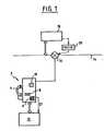
- La figure 1 est une vue simplifiée d'un système d'authentification pour un poste téléphonique conforme à l'invention;
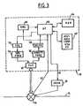
- La figure 2 montre le circuit d'authentification associé au poste téléphonique ;
- La figure 3 montre en détail les circuits du dispositif de contrôle monté sur la ligne téléphonique ; et
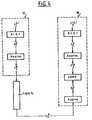
- La figure 4 montre une partie de l'organigramme mis en oeuvre pour comparer les deuxièmes fréquences.
- Figure 1 is a simplified view of an authentication system for a telephone set according to the invention;
- FIG. 2 shows the authentication circuit associated with the telephone set;
- Figure 3 shows in detail the circuits of the control device mounted on the telephone line; and
- Figure 4 shows part of the flow chart used to compare the second frequencies.
En se référant tout d'abord à la figure 1 on va décrire le principe de l'invention. Le terminal, le poste téléphonique 2 dans le cas de la présente description, comprend un combiné 4 un clavier d'entrée de numéros téléphoniques 6, un lecteur de cartes à mémoire 8 et un dispositif d'affichage 10 de façon classique pour les postes téléphoniques à pré paiement.Referring first to Figure 1 we will describe the principle of the invention. The terminal, the telephone set 2 in the case of the present description, comprises a handset 4 a keyboard for entering telephone numbers 6, a
Sur la figure 1 on a également fait apparaître un circuit 12 relié au reste des circuits du poste téléphonique 2 et qui regroupe l'ensemble des circuits propres à la fonction d'authentification au niveau du poste téléphonique 2. Sur la figure 1 on a également représenté une ligne téléphonique 14 sur laquelle est connectée par le branchement 16 le poste 2. La figure 1 montre encore un dispositif de contrôle 18 qui est relié à la ligne 14 et qui peut commander un dispositif d'inhibition 20 capable d'interrompre la transmission de l'information sur la ligne ou de la rendre inaudible.In FIG. 1, a
Ce dispositif de contrôle 18 échange, pendant toute la durée d'une communication téléphonique, avec le poste 2 des informations sous forme de signaux à très bas niveau (-50dB par exemple) ayant des fréquences non audibles pour l'oreille humaine.This
Le poste téléphonique 2 émet avec une périodicité fixe T ,par exemple toutes les deux secondes, un couple de fréquences
Les fréquences f; sont toutes égales et servent à identifier le poste téléphonique 2. Les fréquences f2 changent à chaque fois qu'un nouveau couple de fréquences est émis par le poste téléphonique.The frequencies f; are all equal and are used to identify
Le problème à résoudre vient en partie du fait que la plage de fréquence utilisable est limitée, par exemple de 25kHz à 35kHz, et qu'il y a une incertitude sur la fréquence effectivement élaborée par le téléphone, et sur la fréquence effectivement décodée par le dispositif de contrôle 18.Cette incertitude peut être chiffrée à ± 5 Hz. Cela signifie que dans la plage de fréquence définie ci-dessus, on ne peut utiliser effectivement que 1000 fréquences différentes, c'est à dire 1000 informations différentes.The problem to be solved comes in part from the fact that the usable frequency range is limited, for example from 25 kHz to 35 kHz, and that there is uncertainty about the frequency actually produced by the telephone, and on the frequency effectively decoded by the control device 18.This uncertainty can be calculated at ± 5 Hz. This means that in the frequency range defined above, only 1000 different frequencies can be effectively used, that is to say 1000 different pieces of information.
Pour obtenir cependant une authentification efficace on utilise de préférence le procédé suivant :
- la fréquence f8 est définie de la manière suivante :


- X clé publique, nombre premier (64 bits)
- D clé publique, nombre premier (96 bits)
- E1 nombre aléatoire (64 bits) tiré par le téléphone
- E2 nombre aléatoire (64 bits) tiré par le circuit de contrôle.


- the frequency f8 is defined as follows:
- X public key, prime number (64 bits)
- D public key, prime number (96 bits)
- E1 random number (64 bits) drawn by the telephone
- E2 random number (64 bits) drawn by the control circuit.
Le circuit 12 du poste téléphonique 2 calcule (code RSA) :

La mise en oeuvre du code R S A à clé publique est bien connue. Pour avoir plus de détails on pourra se reporter au brevet américain 4.405.829.The implementation of the R S A public key code is well known. For more details, reference may be made to US Patent 4,405,829.
Le téléphone 2 et le circuit de contrôle 18 échangent Y et Z, ce qui permet à chacun d'eux de calculer une première valeur initiale commune
Le fonctionnement pratique simplifié du système est le suivant :
- Préalablement à l'établissement de la communication téléphonique, les nombres Y et Z sont élaborés et échangés sous forme de fréquences.
- Prior to the establishment of telephone communication, the numbers Y and Z are worked out and exchanged in the form of frequencies.
De préférence Y et Z sont transmis de la manière suivante :
- Y et Z comportent 96 bits, soit 32 chiffres allant de 0 à 7 ou encore 8 nombres de 4 chiffres allant de 0 à 7.
- On peut poser formellement Y = ni, n2... n8
- ni i [1,8] étant des nombres à 4 chiffres compris entre 0 et 7.
- On peut alors poser :
- Yi = (ni + 25.000) Hz. La transmission de Y consistera alors dans la transmission des huit fréquences Y1 à Y8.
- Y and Z have 96 bits, either 32 digits ranging from 0 to 7 or 8 4-digit numbers ranging from 0 to 7.
- We can formally set Y = ni, n2 ... n8
- ni i [1,8] being 4-digit numbers between 0 and 7.
- We can then ask:
- Yi = (ni + 25,000) Hz. The transmission of Y will then consist in the transmission of the eight frequencies Y1 to Y8 .
Ainsi le poste téléphonique 2 et le circuit de contrôle 18 peuvent élaborer la première valeur initiale K1. Par ailleurs ils ont en mémoire les algorithmes ALG1 et ALG2.Thus the telephone set 2 and the
A l'établissement de la communication téléphonique, le poste téléphonique émet la fréquence caractéristique
A partir de
de la ligne de transmission, et du décodage de la fréquence à la réception. Cette approximation est typiquement de ± 5Hz.of the transmission line, and of the decoding of the frequency on reception. This approximation is typically ± 5Hz.
A la lecture de la description précédente on comprend que le système selon l'invention permet effectivement d'éviter tous les types de fraude.Comme la première valeur initiale Ki est différente pour chaque communication et que cette valeur intervient pour la définition des valeurs successives de deuxièmes fréquences, il n'est pas possible de tenter de frauder en enregistrant les valeurs de deuxième fréquence lors d'une communication normale et en réutilisant les valeurs enregistrées pour établir une communication frauduleuse. De même, comme chaque valeur de deuxième fréquence dépend de la valeur initiale Kn correspondante, la probabilité pour que l'algorithme ALG1 élabore des valeurs de deuxièmes fréquences identiques est quasiment nulle, ce qui permet d'empecher un autre type de fraude.Reading the preceding description, it will be understood that the system according to the invention effectively makes it possible to avoid all types of fraud. As the first initial value Ki is different for each communication and that this value intervenes for the definition of successive values of second frequencies, it is not possible to attempt to defraud by recording the values of second frequency during a normal communication and by reusing the values recorded to establish a fraudulent communication. Likewise, since each second frequency value depends on the corresponding initial value Kn , the probability that the algorithm ALG1 will develop values of identical second frequencies is almost zero, which makes it possible to prevent another type of fraud.
En se référenant maintenant à la figure 2 on va décrire plus en détail le circuit 12 du poste téléphonique 2 servant à mettre en oeuvre la procédure d'authentification. Le circuit 12 reçoit sur son entrée 22 le signal DT correspondant à l'instant de début de taxation. Le circuit 12 reçoit également sur son entrée 24 le signal FC de fin de communication. Il reçoit enfin sur son entrée 26 les signaux de fréquence reçus par les circuits téléphonique du poste 2. Le circuit 12 comprend essentiellement un microprocesseur 28 associé à une mémoire de programme et de données fixes 30 et à une mémoire volatile inscriptible 32. Par exemple la mémoire 30 est une PROM et la mémoire 32 est une RAM. Le circuit 12 comporte également des circuits d'interface et de synchronisation. Plus précisément il comprend un filtre 34 relié à l'entrée 26. Ce filtre 34 a pour fonction de ne laisser passer que les signaux de fréquence dans la plage de fréquence utilisée pour les signaux d'authentification c'est à dire typiquement dans la plage 25 à 35 kHz. Le filtre 34 est relié d'une part à un analyseur de fréquence 36 et d'autre part à un générateur de fréquence 38. La sortie 40 du microprocesseur 28 est reliée à l'entrée de commande du générateur de fréquence 38 par l'intermédiaire d'un circuit de codage 42.Referring now to Figure 2 we will describe in more detail the
Symétriquement l'entrée 44 du microprocesseur 28 est reliée à la sortie de l'analyseur de fréquence 36 par un circuit de décodage 46. Enfin le circuit 12 comporte un circuit de synchronisation 48 qui reçoit sur son entrée de commande 48a le signal de début de taxation appliqué à l'entrée 22 du circuit 12. Le circuit de synchronisation 48 a pour fonction d'émettre une impulsion d'initialisation à la réception du signal DT et puis d'émettre des signaux d'horloge de période T après une durée initiale to à compter de la réception du signal DT.Symmetrically the
La mémoire 30 comporte essentiellement les instructions et éléments de programme permettant la mise en oeuvre des algorithmes ALG1 et ALG2, la mise en oeuvre du programme de codage à clé publique RSA, les éléments d'élaboration de la valeur initiale Ki ainsi que des instructions permettant le déroulement de l'ensemble du programme qui sera décrit ci-après. La mémoire 32 permet d'effectuer et de mémoriser les résultats intermédiaires correspondant à la mise en oeuvre des différents algorithmes ainsi qu'à mémoriser les différentes valeurs des fréquences
La figure 3 montre les circuits du dispositif de contrôle 18. Il comprend un filtre d'entrée 50 qui ne laisse passer que les signaux d'authentification c'est-à-dire les signaux dont la fréquence est comprise entre 25 et 35kHz. Au filtre 50 sont associés un analyseur de fréquence 52 et un générateur de fréquence 54. Le générateur 54 est commandé par un circuit de codage 56 alors que la sortie de l'analyseur de fréquence 52 est reliée à un circuit de décodage 58. Le dispositif de contrôle 18 comprend également un microprocesseur 60 associé à une mémoire de programme et de données fixes 62 et à une mémoire inscriptible volatile 64. La mémoire 62 contient les sous programmes nécessaires pour la mise en oeuvre des algorithmes ALG1 et ALG2, le programme RSA à clé publique, un programme de comparaison COMP et les données E2, D et X associées au programme RSA. Le dispositif 18 comprend enfin un circuit de synchronisation 66 qui a la même fonction que le circuit de synchronisation 48 du circuit 12, et qui est déclenché par l'application sur son entrée du signal de début de taxation DT.FIG. 3 shows the circuits of the
Le fonctionnement détaillée du système d'authentification est le suivant. Lorsque le signal DT est appliqué sur son entrée 22, le circuit de synchronisation 48 du circuit 12 émet une impulsion d'initialisation qui déclenche un intervalle de temps initial to. Pendant cet intervalle de temps le micro processeur 28 élabore la valeur Y et la transmet au dispositif de contrôle 18 et à partir de la valeur Z qu'il reçoit du dispositif de contrôle 18 il élabore la grandeur initiale Ki. Pour cela, sous le contrôle du programme RSA stocké dans la mémoire 30, et à partir des clés publiques X et D et de la valeur E1 qui sont également stockées dans la mémoire 30, le microprocesseur 28 calcule le nombre Y. Le circuit de codage 42, élabore les huit nombres à quatre chiffres ni correspondants. A partir de ces huit nombres ni le générateur de fréquence 38 élabore les huit fréquences correspondance Yi qui sont envoyées sur la ligne 14 pour être reçues par le dispositif de contrôle 18.The detailed operation of the authentication system is as follows. When the signal DT is applied to its input 22, the
Symétriquement, à la réception du signal de début de taxation DT, le dispositif de contrôle 18 élabore les huit fréquences Zi correspondant à la valeur Z du code RSA et les envoie sur la ligne 14 pour qu'elles soient reçues par le circuit 12 du poste téléphonique 2.Symmetrically, on receipt of the charging start signal DT, the
A la réception des fréquences Zi, l'analyseur de fréquence 36 et le circuit de décodage 46 élabore les nombres correspondants ni et donc finalement le nombre Z qui est stocké temporairement dans la mémoire 32. A partir de la valeur Z, et sous le contrôle du programme RSA, le micro processeur 28 calcule la première valeur initiale Ki qui est à son tour mémorisée dans la mémoire 32. De même à la réception des fréquences Yi, le dispositif de contrôle 18 détermine par un processus analogue la valeur de Y et calcule la valeur initiale Ki qui est stockée dans la mémoire 64.On reception of the frequencies Zi , the frequency analyzer 36 and the decoding circuit 46 elaborates the corresponding numbers ni and therefore finally the number Z which is temporarily stored in the
A l'expiration de l'intervalle de temps to les circuits de synchronisation 48 et 66 émettent une nouvelle impulsion. A la réception de cette impulsion le circuit 12 émet la première fréquence
Après qu'un temps T se soit écoulé, les circuits de synchronisation 48 et 66 émettent une nouvelle impulsion d'horloge. A la réception de cette impulsion, le microprocesseur 28 du circuit 12, calcule la deuxième valeur K2 de Ki par mise en oeuvre de l'algorithme ALG2 et la deuxième valeur de deuxième fréquence f2 par mise en oeuvre de l'algorithme ALG1. Simultanément le microprocesseur 66 du circuit 18 calcule la deuxième valeur K2 de Ki et la deuxième valeur de deuxième fréquence f2 par mise en oeuvre des algorithmes ALG1, ALG2 et à partir de la valeur f2 déjà mémorisée. Lorsque le dispositif de contrôle 18 reçoit la deuxième valeur de deuxième fréquence
Si l'on veut décrire plus en détail le fonctionnement du système en tenant compte de l'approximation, il est le suivant :
- A partir de la fréquence
 . Ce nombre qui est compris entre 25000 et 35000 est remplacé par une valeur approximée de
 , cette valeur approximée étant fn2 . L'approximation est la suivante :
- Soit x le chiffre des unités de la valeur pn2 ;
- si o < x < 5 on passe de p8 à f8 en remplaçant x par o et en conservant le chiffre des dizaines et si 5 < x <9 on passe de p8 àf2n en remplaçant x par o et en remplaçant le chiffre des dizaines par le chiffre immédiatement supérieur. En d'autres termes fn2 est égale à pn2 arrondie à la dizaine inférieure si x < 5, et arrondie à la dizaine supérieure si x > 5.
- La fréquence approximée fn2 est transmise sur la ligne 14 par le générateur de fréquence 38. Lors de la transmission sur la ligne la fréquence peut être légèrement modifiée. L'analyseur de fréquence 52 délivre une valeur qn2 . Le microprocesseur 60 calcule la valeur approximée de qn2 par la technique d'approximation déjà décrite, cette valeur approximée étant gn2 . On comprend que gn2 = fn2 . Le microprocesseur 60 calcule f'n2 également en deux temps. Tout d'abord par mise en oeuvre de l'algorithme ALG1 le microprocesseur calcule vn2 à partir de


- Il va de soit que les approximations, au lieu d'être mises en oeuvre par des éléments de programme des microprocesseurs 28
et 60, pourraient l'être par des circuits numériques spécifiques comprenant des compteurs et des comparateurs. - Les circuits qui viennent d'être décrits sont spécifiques à l'authentification de la communication, mais il va de soi que le poste téléphonique 2 comporte tous les circuits classiques d'un poste téléphonique à pré-paiement et à taxation locale. Ces circuits sont en eux-mêmes bien connus.


- From frequency
microprocessor 28 calculates the value f8 in two stages. First of all it calculates by implementation of the algorithm ALG1 a number. This number which is between 25000 and 35000 is replaced by an approximate value of, this approximate value being fn2 . The approximation is as follows:- Let x be the digit of the units of the value pn2 ;
- if o <x <5 we go from p8 to f8 by replacing x by o and keeping the tens digit and if 5 <x <9 we go from p8 tof2n by replacing x by o and replacing the numbers of tens by the next higher number. In other words fn2 is equal to pn2 rounded to the nearest ten if x <5, and rounded to the top ten if x> 5.
- The approximate frequency fn2 is transmitted on
line 14 by thefrequency generator 38. When transmitting on the line the frequency can be slightly modified. The frequency analyzer 52 delivers a value qn2 . Themicroprocessor 60 calculates the approximate value of qn2 by the approximation technique already described, this approximate value being gn2 . We understand that gn2 = fn2 . Themicroprocessor 60 also calculates f 'n2 in two stages. First of all by implementing the ALG1 algorithm the microprocessor calculates vn2 from - It goes without saying that the approximations, instead of being implemented by program elements of the
microprocessors - The circuits which have just been described are specific to the authentication of the communication, but it goes without saying that the telephone set 2 includes all the conventional circuits of a prepaid telephone set and local charging. These circuits are in themselves well known.
Claims (7)


Applications Claiming Priority (2)
| Application Number | Priority Date | Filing Date | Title |
|---|---|---|---|
| FR8705503 | 1987-04-17 | ||
| FR8705503AFR2614162B1 (en) | 1987-04-17 | 1987-04-17 | ANALOGUE AUTHENTICATION SYSTEM RECIPROCED BETWEEN A TERMINAL AND A TRANSMISSION LINE |
Publications (2)
| Publication Number | Publication Date |
|---|---|
| EP0292342A1 EP0292342A1 (en) | 1988-11-23 |
| EP0292342B1true EP0292342B1 (en) | 1992-07-22 |
Family
ID=9350252
Family Applications (1)
| Application Number | Title | Priority Date | Filing Date |
|---|---|---|---|
| EP88400896AExpired - LifetimeEP0292342B1 (en) | 1987-04-17 | 1988-04-14 | System for the reciprocal analogous authentication between a terminal and a transmission line |
Country Status (5)
| Country | Link |
|---|---|
| US (1) | US4852155A (en) |
| EP (1) | EP0292342B1 (en) |
| JP (1) | JPS6429048A (en) |
| DE (1) | DE3872942T2 (en) |
| FR (1) | FR2614162B1 (en) |
Families Citing this family (25)
| Publication number | Priority date | Publication date | Assignee | Title |
|---|---|---|---|---|
| FR2646305B1 (en)* | 1989-04-19 | 1991-06-14 | Dassault Electronique | ELECTRONIC CODING DEVICE, ESPECIALLY FOR PUBLIC PHONE |
| US5311596A (en)* | 1992-08-31 | 1994-05-10 | At&T Bell Laboratories | Continuous authentication using an in-band or out-of-band side channel |
| US5488649A (en)* | 1994-05-06 | 1996-01-30 | Motorola, Inc. | Method for validating a communication link |
| DK11995A (en)* | 1994-05-02 | 1995-11-03 | Christian Henri Krause | Telephone system fuse |
| US5854975A (en)* | 1994-12-23 | 1998-12-29 | Freedom Wireless, Inc. | Prepaid security cellular telecommunications system |
| FR2734115B1 (en)* | 1995-05-12 | 1997-08-01 | Schlumberger Ind Sa | SECURE TELEPHONE INSTALLATION |
| FR2742950B1 (en)* | 1995-12-22 | 1998-03-27 | Monetel | ANTI-FRAUD SYSTEM FOR TELEPHONE LINE |
| IT1291472B1 (en)* | 1997-01-27 | 1999-01-11 | Urmet Sud Costruzioni Elettro | OBLITERATION FEEDING DEVICE FOR PUBLIC TELEPHONE EQUIPMENT. |
| FR2777404B1 (en)* | 1998-04-10 | 2000-05-19 | Schlumberger Ind Sa | DEVICE FOR SECURING A TELEPHONE LINE |
| FR2779308B1 (en)* | 1998-05-27 | 2000-06-30 | Schlumberger Ind Sa | DEVICE FOR SECURING A TELEPHONE LINE |
| US6704563B1 (en) | 1998-08-11 | 2004-03-09 | Boston Communications Group, Inc. | Systems and methods for prerating costs for a communication event |
| US7187928B1 (en) | 1998-11-24 | 2007-03-06 | Boston Communications Group, Inc. | Call delivery systems for roaming prepaid subscribers |
| AU2001239831A1 (en) | 2000-02-25 | 2001-09-03 | Telecommunication Systems, Inc. | Prepaid short messaging |
| US7110773B1 (en) | 2000-04-11 | 2006-09-19 | Telecommunication Systems, Inc. | Mobile activity status tracker |
| US7640031B2 (en) | 2006-06-22 | 2009-12-29 | Telecommunication Systems, Inc. | Mobile originated interactive menus via short messaging services |
| US6658260B2 (en) | 2001-09-05 | 2003-12-02 | Telecommunication Systems, Inc. | Inter-carrier short messaging service providing phone number only experience |
| US7853272B2 (en) | 2001-12-21 | 2010-12-14 | Telecommunication Systems, Inc. | Wireless network tour guide |
| US8195205B2 (en) | 2004-05-06 | 2012-06-05 | Telecommunication Systems, Inc. | Gateway application to support use of a single internet address domain for routing messages to multiple multimedia message service centers |
| US7991411B2 (en) | 2004-05-06 | 2011-08-02 | Telecommunication Systems, Inc. | Method to qualify multimedia message content to enable use of a single internet address domain to send messages to both short message service centers and multimedia message service centers |
| US7430425B2 (en) | 2005-05-17 | 2008-09-30 | Telecommunication Systems, Inc. | Inter-carrier digital message with user data payload service providing phone number only experience |
| US7548158B2 (en) | 2005-08-08 | 2009-06-16 | Telecommunication Systems, Inc. | First responder wireless emergency alerting with automatic callback and location triggering |
| US8954028B2 (en)* | 2008-09-25 | 2015-02-10 | Telecommunication Systems, Inc. | Geo-redundant and high reliability commercial mobile alert system (CMAS) |
| US8712453B2 (en) | 2008-12-23 | 2014-04-29 | Telecommunication Systems, Inc. | Login security with short messaging |
| WO2012082151A2 (en) | 2010-12-13 | 2012-06-21 | Telecommunication Systems, Inc. | Location services gateway server |
| US9408047B2 (en) | 2013-10-10 | 2016-08-02 | Telecommunication Systems, Inc. | Read acknowledgement interoperability for text messaging and IP messaging |
Family Cites Families (4)
| Publication number | Priority date | Publication date | Assignee | Title |
|---|---|---|---|---|
| US4467140A (en)* | 1981-05-01 | 1984-08-21 | Masco Corporation Of Indiana | Microprocessor-based cordless telephone system |
| US4625078A (en)* | 1983-12-30 | 1986-11-25 | At&T Technologies Inc. | Fraud prevention in an electronic coin telephone set |
| DE3410937A1 (en)* | 1984-03-24 | 1985-10-03 | Philips Patentverwaltung Gmbh, 2000 Hamburg | Method for identifying the unauthorised use of an identifier |
| DE3420460A1 (en)* | 1984-06-01 | 1985-12-05 | Philips Patentverwaltung Gmbh, 2000 Hamburg | METHOD FOR DETECTING THE UNAUTHORIZED USE OF AN IDENTIFICATION ASSIGNED TO A MOVABLE RADIO STATION IN A RADIO TRANSMISSION SYSTEM |
- 1987
- 1987-04-17FRFR8705503Apatent/FR2614162B1/ennot_activeExpired - Fee Related
- 1988
- 1988-04-14DEDE8888400896Tpatent/DE3872942T2/ennot_activeExpired - Lifetime
- 1988-04-14EPEP88400896Apatent/EP0292342B1/ennot_activeExpired - Lifetime
- 1988-04-14USUS07/181,605patent/US4852155A/ennot_activeExpired - Fee Related
- 1988-04-18JPJP63095380Apatent/JPS6429048A/enactivePending
Also Published As
| Publication number | Publication date |
|---|---|
| FR2614162B1 (en) | 1993-12-10 |
| DE3872942T2 (en) | 1992-12-03 |
| US4852155A (en) | 1989-07-25 |
| EP0292342A1 (en) | 1988-11-23 |
| DE3872942D1 (en) | 1992-08-27 |
| FR2614162A1 (en) | 1988-10-21 |
| JPS6429048A (en) | 1989-01-31 |
Similar Documents
| Publication | Publication Date | Title |
|---|---|---|
| EP0292342B1 (en) | System for the reciprocal analogous authentication between a terminal and a transmission line | |
| EP0335768B1 (en) | Pre-payment information transmission system | |
| CA2112518C (en) | Process for the authentication of at least one identification device using a verification device and implementation device | |
| FR2597235A1 (en) | POSTAGE DEVICE WITH BACKFILL SYSTEM, AND METHOD FOR IMPLEMENTING SAME | |
| FR2607292A1 (en) | ELECTRONIC POSTAGE DEVICE WITH CLOCK AND METHOD FOR ADJUSTING THE CLOCK | |
| CH625633A5 (en) | ||
| WO1999018546A1 (en) | Authenticating system with microcircuit card | |
| EP0463384A1 (en) | Method of access to a cordless telephone service | |
| FR2597231A1 (en) | POSTAGE DEVICE WITH COMMUNICATION SYSTEM, AND METHOD FOR IMPLEMENTING SAME | |
| CA2634612A1 (en) | System and method for dial tones screening | |
| FR2640835A1 (en) | AUTHENTICATION DEVICE FOR INTERACTIVE SERVER | |
| FR2471098A1 (en) | INSTALLATION FOR TELEPHONING WITHOUT COINS | |
| US4074079A (en) | Coin telephone antifraud system | |
| FR2561841A1 (en) | Identification code monitoring circuit | |
| FR2744822A1 (en) | TRANSMISSION SYSTEM INCLUDING TERMINAL DEVICES EQUIPPED WITH A PRE-PAYMENT CIRCUIT AND PROCESS IMPLEMENTED IN SUCH A SYSTEM | |
| WO1996036162A1 (en) | Subscriptionless telephone, control module therefor and secure telephone equipment including the telephone and security module | |
| WO1999049647A1 (en) | Mobile telephone system with prepaid card | |
| EP1978479A1 (en) | Dynamic cryptogram | |
| FR2685111A1 (en) | INSTALLATION FOR VERIFYING SECURITY IDENTIFICATION INFORMATION IN CONNECTION WITH A LIST OF SECURED OPPOSITION SECURITIES. | |
| EP0272954B1 (en) | Device for initiating the metering for a public telephone | |
| FR2646305A1 (en) | Electronic coding device especially for public telephones | |
| EP1097567B1 (en) | Telephone equipped with automatic dialling means | |
| FR3126514A1 (en) | Strong asynchronous authentication method and terminal configured for the implementation of said method. | |
| EP1179257A1 (en) | Method and device for detecting the unauthorized use of a telephone line | |
| FR2784840A1 (en) | Public telephone security device, to prevent interference with smart card credit consumption, senses call charge acknowledgement signals transmitted by payphone using sub-audible frequency line current modulation |
Legal Events
| Date | Code | Title | Description |
|---|---|---|---|
| PUAI | Public reference made under article 153(3) epc to a published international application that has entered the european phase | Free format text:ORIGINAL CODE: 0009012 | |
| AK | Designated contracting states | Kind code of ref document:A1 Designated state(s):BE CH DE ES GB IT LI NL SE | |
| 17P | Request for examination filed | Effective date:19890104 | |
| 17Q | First examination report despatched | Effective date:19910516 | |
| GRAA | (expected) grant | Free format text:ORIGINAL CODE: 0009210 | |
| AK | Designated contracting states | Kind code of ref document:B1 Designated state(s):BE CH DE ES GB IT LI NL SE | |
| PG25 | Lapsed in a contracting state [announced via postgrant information from national office to epo] | Ref country code:IT Free format text:LAPSE BECAUSE OF FAILURE TO SUBMIT A TRANSLATION OF THE DESCRIPTION OR TO PAY THE FEE WITHIN THE PRE;WARNING: LAPSES OF ITALIAN PATENTS WITH EFFECTIVE DATE BEFORE 2007 MAY HAVE OCCURRED AT ANY TIME BEFORE 2007. THE CORRECT EFFECTIVE DATE MAY BE DIFFERENT FROM THE ONE RECORDED.SCRIBED TIME-LIMIT Effective date:19920722 Ref country code:SE Effective date:19920722 Ref country code:ES Free format text:THE PATENT HAS BEEN ANNULLED BY A DECISION OF A NATIONAL AUTHORITY Effective date:19920722 Ref country code:NL Effective date:19920722 | |
| REF | Corresponds to: | Ref document number:3872942 Country of ref document:DE Date of ref document:19920827 | |
| GBT | Gb: translation of ep patent filed (gb section 77(6)(a)/1977) | ||
| NLV1 | Nl: lapsed or annulled due to failure to fulfill the requirements of art. 29p and 29m of the patents act | ||
| PG25 | Lapsed in a contracting state [announced via postgrant information from national office to epo] | Ref country code:GB Effective date:19930414 | |
| PG25 | Lapsed in a contracting state [announced via postgrant information from national office to epo] | Ref country code:BE Effective date:19930430 Ref country code:LI Effective date:19930430 Ref country code:CH Effective date:19930430 | |
| PLBE | No opposition filed within time limit | Free format text:ORIGINAL CODE: 0009261 | |
| STAA | Information on the status of an ep patent application or granted ep patent | Free format text:STATUS: NO OPPOSITION FILED WITHIN TIME LIMIT | |
| 26N | No opposition filed | ||
| BERE | Be: lapsed | Owner name:SCHLUMBERGER INDUSTRIES Effective date:19930430 | |
| GBPC | Gb: european patent ceased through non-payment of renewal fee | Effective date:19930414 | |
| REG | Reference to a national code | Ref country code:CH Ref legal event code:PL | |
| PG25 | Lapsed in a contracting state [announced via postgrant information from national office to epo] | Ref country code:DE Effective date:19940101 |