EP0286496A1 - Helmet-mounted, binocular, holographic view finder with wide field of vision - Google Patents
Helmet-mounted, binocular, holographic view finder with wide field of visionDownload PDFInfo
- Publication number
- EP0286496A1 EP0286496A1EP88400701AEP88400701AEP0286496A1EP 0286496 A1EP0286496 A1EP 0286496A1EP 88400701 AEP88400701 AEP 88400701AEP 88400701 AEP88400701 AEP 88400701AEP 0286496 A1EP0286496 A1EP 0286496A1
- Authority
- EP
- European Patent Office
- Prior art keywords
- image
- hologram
- combiner
- vision
- optical
- Prior art date
- Legal status (The legal status is an assumption and is not a legal conclusion. Google has not performed a legal analysis and makes no representation as to the accuracy of the status listed.)
- Granted
Links
- 230000004438eyesightEffects0.000titleclaimsabstractdescription28
- 230000003287optical effectEffects0.000claimsabstractdescription49
- 230000005855radiationEffects0.000claimsdescription8
- 230000005499meniscusEffects0.000claimsdescription7
- 210000001747pupilAnatomy0.000claimsdescription7
- 230000005540biological transmissionEffects0.000claimsdescription6
- 230000004075alterationEffects0.000claimsdescription5
- 230000003595spectral effectEffects0.000claimsdescription3
- 238000001228spectrumMethods0.000claimsdescription3
- 239000012780transparent materialSubstances0.000claimsdescription2
- 230000000694effectsEffects0.000claims1
- 238000010586diagramMethods0.000description9
- 239000011521glassSubstances0.000description3
- 238000001429visible spectrumMethods0.000description3
- 239000000463materialSubstances0.000description2
- 230000037361pathwayEffects0.000description2
- 230000009466transformationEffects0.000description2
- 238000011144upstream manufacturingMethods0.000description2
- 229920000297RayonPolymers0.000description1
- 230000004308accommodationEffects0.000description1
- 230000007547defectEffects0.000description1
- 210000000887faceAnatomy0.000description1
- 238000001093holographyMethods0.000description1
- 230000006872improvementEffects0.000description1
- 239000007788liquidSubstances0.000description1
- 239000004973liquid crystal related substanceSubstances0.000description1
- 239000011159matrix materialSubstances0.000description1
- 238000000034methodMethods0.000description1
- 230000004048modificationEffects0.000description1
- 238000012986modificationMethods0.000description1
- 230000010287polarizationEffects0.000description1
- 239000002964rayonSubstances0.000description1
- 238000004088simulationMethods0.000description1
- 238000009966trimmingMethods0.000description1
- 230000000007visual effectEffects0.000description1
Images


Classifications
- G—PHYSICS
- G02—OPTICS
- G02B—OPTICAL ELEMENTS, SYSTEMS OR APPARATUS
- G02B27/00—Optical systems or apparatus not provided for by any of the groups G02B1/00 - G02B26/00, G02B30/00
- G02B27/01—Head-up displays
- G02B27/0101—Head-up displays characterised by optical features
- G02B27/0103—Head-up displays characterised by optical features comprising holographic elements
- G—PHYSICS
- G02—OPTICS
- G02B—OPTICAL ELEMENTS, SYSTEMS OR APPARATUS
- G02B27/00—Optical systems or apparatus not provided for by any of the groups G02B1/00 - G02B26/00, G02B30/00
- G02B27/01—Head-up displays
- G02B27/017—Head mounted
- G02B27/0172—Head mounted characterised by optical features
- G—PHYSICS
- G02—OPTICS
- G02B—OPTICAL ELEMENTS, SYSTEMS OR APPARATUS
- G02B27/00—Optical systems or apparatus not provided for by any of the groups G02B1/00 - G02B26/00, G02B30/00
- G02B27/01—Head-up displays
- G02B27/0101—Head-up displays characterised by optical features
- G02B27/0103—Head-up displays characterised by optical features comprising holographic elements
- G02B2027/0105—Holograms with particular structures
- G02B2027/0107—Holograms with particular structures with optical power
- G—PHYSICS
- G02—OPTICS
- G02B—OPTICAL ELEMENTS, SYSTEMS OR APPARATUS
- G02B27/00—Optical systems or apparatus not provided for by any of the groups G02B1/00 - G02B26/00, G02B30/00
- G02B27/01—Head-up displays
- G02B27/0101—Head-up displays characterised by optical features
- G02B2027/0145—Head-up displays characterised by optical features creating an intermediate image
Definitions
- the present inventionrelates to a binocular, holographic and wide field viewfinder.
- viewfinderis meant a device in which a collimated light image is observed superimposed on the vision of the exterior landscape.
- a collimating opticreturns to infinity the light image corresponding to the data to be collimated; this results in the absence of accommodation for the eye of the observer and great visual comfort.
- the light imageis returned by a combination optic to the observer; this optic is crossed by radiation from the outside landscape.
- the observersuch as the pilot of an aircraft, sees in superimposition on the landscape the collimated light image corresponding, for example, to a synthetic image of piloting data.
- a known solutionconsists in using a spherical mirror on the axis which also makes it possible to limit optical aberrations.
- the optical axis of the spherical mirrorcorresponds to the normal line of vision of the observer whose eye is placed at the center of mirror; the latter is combined with a semi-transparent plane mirror which has the role of reflecting the optical axis of the light image generator towards the spherical mirror on the concave side which produces the collimation and sends the collimated image back to the observer.
- a holographic spherical mirrorwhich reflects the wavelength corresponding to the image generator which may consist of a cathode ray tube display.
- the main drawback of this solutionis that the circular field, although enlarged, remains however limited to values of the order of 30 ° to 40 ° in monocular vision.
- a semi-transparent plane mirroris used to return the axis of the generator of light images to the eye of the observer.
- the corresponding radiation reflected by this mirrorpasses through a spherical mirror, which is followed by a birefringent plane mounting perpendicular to the optical axis of the spherical mirror corresponding to the normal direction of vision.
- This birefringent assemblycooperates with an upstream polarizer to polarize the radiation of the light image and makes it possible to recover it after collimation by the spherical mirror.
- the object of the inventionis to remedy the aforementioned drawbacks and to produce a display device with a still enlarged field and a significant energy yield while constituting an ergonomic system.
- the solution proposed in the followingmakes it possible to easily obtain, in binocular vision, a field of the order of 60 ° in site on approximately 120 ° in deposit, with yields of the order of 40% for the image channel and 30% for the landscape channel.
- Another object of the inventionis the use on a helmet of a binocular sight according to the invention.
- the aforementioned aimis achieved by producing a binocular viewfinder using, in monocular vision, a collimator device grouping successively: a generator of a light image to be collimated, an optical relay formula, and an optical collimation and combination set, this set being composed of a mixing optical element to transmit the landscape path and reflect the image path and which is followed by two collimating optical elements including a first spherical element used on the axis, to transmit the two paths with collimation of the image path.
- the mixing optical element, as well as the two collimating optical elementseach have a hologram.
- the mixing optical elementpreferably consists of a flat holographic plate whose hologram is of the mirror type which makes it possible to ensure a high transmission of the landscape pathway together with an optimal reflection of the image pathway.
- the second collimating optical elementis also spherical like the first and coaxial with it, but of smaller curvature, to form with this first element a bi-convex assembly arranged downstream of the optical mixing element in the direction of the optical path of the image channel.
- the holograms of the two collimating optical elementsare determined to ensure diffraction by reflection in a defined spectral band corresponding to that of the image channel.
- the inventionrelates to a sighting device, adaptable to a helmet, the binocular field of which can reach 60 ° ⁇ 120 ° and the general appearance of which in operation is briefly indicated in FIG. 1. It consists of two similar parts each providing vision monocular and successively comprising: a generator 1A-1B of a light image to be collimated, an optical relay formula 2A-2B, and an optical assembly of collimation and combination composed of an element optical holographic mixer 3A, 3B, and two optical elements holographic collimators 4A-4B.
- the imagecan be produced using a miniature cathode ray tube 1A-1B for each eye.
- the imagescan be the same or different.
- the relay optics 2A-2Bis bent for reasons of space, for example by means of a prismatic structure.
- the optical mixing element 3A-3Bis formed using a flat blade which ensures the transmission of the path from the outside landscape and the reflection of the image path from the tube.
- the flat platehas a hologram in order to increase the photometric efficiency on the tube channel by reflecting only the reduced wavelength spectrum corresponding to the image channel and by transmitting all the other wavelengths of the visible spectrum without attenuation .
- the collimator optic 4A-4Bknown as the combiner in what follows, infinitely collimates the image coming from the relay optics and reflected by the blade 3A-3B, and it transmits the light radiation from the landscape path without modification.
- Figure 2shows the combination of elements involved in monocular vision.
- three holograms H1, H2 and H3placed respectively on the mixing blade 3A and on two optical elements 41 and 42 constituting the combiner 4A.
- the optical element 41has a spherical shape; the optical element 42 also has a spherical shape but of lesser curvature.
- the assemblyforms a biconvex optic used on the axis.
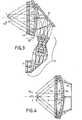
- Figures 3 and 4illustrate the optical path of the image channel for each monocular vision chain.
- the field radiiare shown for three directions the axial direction and two directions symmetrical with respect to the axial direction. It is noted that the direction of the central axis or optical axis of the system, does not undergo collimation. This results in an area of zero photometric efficiency and therefore a black hole in the monocular field. This defect is compensated by the overlap of fields in binocular, as we will see later.
- the pupil of the eye P o(more precisely it is the eye box, that is to say the area where one can move the eye without impairing vision) is conjugated with the pupil relay optics.
- the field in elevation represented in FIG. 3Acorresponds to ⁇ 30 ° and that in deposit appearing in FIG. 4 in top view is ⁇ 42.5 °, ie 85 ° lateral for 60 ° high in monocular vision.
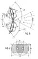
- FIG. 5illustrates the overlap of the fields in binocular vision, the eyes being at the distance D1 of the order of 6.5 cm, the collimation optics 4A-4B being arranged as shown, making an angle between them ensuring the desired overlap, by example of 50 ° in the embodiment concerned, so as to cover the axial black hole relating to the monocular vision of the other eye as illustrated in FIG. 6.
- the left and right nonocular fields, of circular shape,are referenced there CG and CD.
- the height trimmingresults from the size and dimensions of the mixing blades 3A-3B placed upstream (see Fig. 1).
- the optical characteristics of the viewfinderare as follows for the embodiment considered: circular monocular field of 85 °; binocular field 60 ° vertically by 120 ° horizontally; eye pupil P o considered to be 15mm in diameter; yield on image channel or tube channel 40%, yield on landscape channel 30%; diameter of the spot on the image path approximately 1.5 bn in the center of the monocular field at approximately 3.5 bn at 40 °.
- the viewfinder according to the inventionhas a high photometric yield, both on the image path and on that of the landscape. This marked improvement is mainly due to the use of the holographic collimator combiner 4A-4B.
- the 4A-4B holographic combinerbehaves like an afocal system on the path of the landscape, that is to say, of external vision. Its focal length is determined according to the size on the image channel. Aberrations on the way image and distortion on the landscape path are minimized. The photometric yields on the two channels are maximized, as well as the diameter of the pupil or eye box P o .
- the architecture of the combinerappears in FIGS. 3 and 4.
- the combinerconsists of two holograms diffracting by reflection the rays coming from the image generating tube which therefore correspond to a fixed wavelength or to a very reduced spectral band, are transmitted by the hologram H2, then diffracted by reflection by the hologram H3, then diffracted by reflection by the hologram H2, and finally transmitted by the hologram H3.
- a hologramis an optical component which, at a fixed wavelength, diffracts the rays falling at a given incidence and transmits without transformation the radiation falling at the other incidences.
- the rays coming from the landscapewhich contain the wavelengths of the visible spectrum are transmitted by the hologram H2 then by the hologram H3.
- the zero photometric efficiency zonecreates a hole in the field of approximately 14 ° in diameter.
- the use in binoculars with the field overlap indicated with the help of Figures 5 and 6overcomes these two zero yield holes.
- the index modulation of each of the two holograms H2 and H3can be made variable depending on the point considered on these holograms.
- the holograms H2 and H3are of the mirror type, that is to say that they act only as interference filters.
- the optical function of such a hologramis equal to that of its support.
- the mirror hologramis produced from known manner, by arranging the layer of photosensitive material to be recorded between a glass slide which constitutes its support and a recording mirror of the same curvature.
- An index adapter liquidmay be provided between the photosensitive material and the mirror.
- FIG. 7indicates the parameters to be considered for an exemplary embodiment of the combiner. These parameters are the radii of curvature R1 to R6 and the positions on the optical axis d1 to d7 of the different blades of the combiner, that is to say the supports 41 and 42 made of glass, or transparent material, and the holograms H2 and H3.
- the distance d1corresponds to the distance between the pupil of the eye P o and the hologram H3.
- the distance d7represents the distance between the hologram H2 and the mixing blade 3A.
- the positions d1 to d7are successively axial.
- the flat holographic blade 3A or 3Bensures mixing between the landscape and the tube path.
- the hologram usedis also of the mirror type.
- the bladeis inclined relative to the axis of the combiner, for example from 40 to 45 °.
- FIG. 8shows in developed form the relay optics 2A already visible in detail in FIG. 3 and which ensures the transport of the image from the tube 1A to the combiner 4A after reflection on the holographic flat blade 3A.
- This opticcompensates for the residual aberrations of the combiner.
- itconsists of a montage of eight lenses and a prism.
- the first element L1constitutes a converging meniscus.
- L2constitutes a converging meniscus.
- L3 grouping a divergent meniscus and a converging meniscusthere is then a triplet L4, L5, L6 consisting of a biconcave lens L4, a biconvex lens L5 and a converging meniscus L6.
- Element L7is a converging meniscus and element L8 is a biconvex lens.
- the terminal prism Pallows the optical path to be folded back and is terminated by curved faces which, on one side, conform to the corresponding spherical diopter of the lens L8 and which are located on the other side in front of the screen of the tube, the thickness of which glass is represented by the end piece V.
- the binocular viewfinderoffered allows a large field of observation; it can be mounted on a helmet.
- the essential applications envisagedare aid to the navigation of pilots of airplanes or helicopters, as well as piloting simulation.
- the image generator 1A or 1Bcan be produced differently, with a liquid crystal matrix for example.
Landscapes
- Physics & Mathematics (AREA)
- General Physics & Mathematics (AREA)
- Optics & Photonics (AREA)
- Diffracting Gratings Or Hologram Optical Elements (AREA)
- Lenses (AREA)
- Telescopes (AREA)
Abstract
Description
Translated fromFrenchLa présente invention concerne un viseur binoculaire, holographique et à grand champ.The present invention relates to a binocular, holographic and wide field viewfinder.
On entend par viseur un dispositif dans lequel une image lumineuse collimatée est observée en superposition sur la vision du paysage extérieur. Une optique collimatrice renvoit à l'infini l'image lumineuse correspondant aux données à collimater ; ceci se traduit par l'absence d'effort d'accomodation pour l'oeil de l'observateur et un grand confort visuel. De manière conventionnelle, l'image lumineuse est renvoyée par une optique de combinaison vers l'observateur ; cette optique est traversée par le rayonnement provenant du paysage extérieur. Ainsi, l'observateur, tel le pilote d'un aéronef, voit en superposition sur le paysage l'image lumineuse collimatée correspondant, par exemple, à une image synthétique de données de pilotage.By viewfinder is meant a device in which a collimated light image is observed superimposed on the vision of the exterior landscape. A collimating optic returns to infinity the light image corresponding to the data to be collimated; this results in the absence of accommodation for the eye of the observer and great visual comfort. Conventionally, the light image is returned by a combination optic to the observer; this optic is crossed by radiation from the outside landscape. Thus, the observer, such as the pilot of an aircraft, sees in superimposition on the landscape the collimated light image corresponding, for example, to a synthetic image of piloting data.
Les techniques récentes dans le domaine des collimateurs tête haute sont dirigées essentiellement vers un accroissement du champ de vision instantanée de l'image collimatée, ainsi que vers l'obtention d'un rendement optique amélioré.The recent techniques in the field of head-up collimators are directed essentially towards an increase in the instantaneous field of vision of the collimated image, as well as towards obtaining an improved optical efficiency.
Une solution connue consiste à utiliser un miroir sphérique sur l'axe ce qui permet également de limiter les aberrations optiques. Suivant une réalisation de ce genre décrite dans la demande de brevet français publiée sous le No2 542 459, l'axe optique du miroir sphérique correspond à l'axe normal de vision de l'observateur dont l'oeil est placé au centre du miroir ; ce dernier est combiné avec un miroir plan semi-transparent qui a pour rôle de renvoyer l'axe optique du générateur d'image lumineuse vers le miroir sphérique côté concave lequel produit la collimation et renvoit l'image collimatée vers l'observateur. Pour accroître le rendement on utilise un miroir sphérique holographique qui réfléchit la longueur d'onde correspondant au générateur d'image qui peut consister en une visualisation à tube cathodique. Le principal inconvénient de cette solution est que le champ circulaire, bien qu'agrandi, reste cependant limité à des valeurs de l'ordre de 30° à 40° en vision monoculaire. Pour un accroissement plus important du champ on est amené à une utilisation hors d'axe du miroir sphérique car le miroir plan partiellement transparent se trouve alors trop rapproché de l'oeil de l'observateur ; il en résulte des aberrations optiques et des difficultés de mise en oeuvre.A known solution consists in using a spherical mirror on the axis which also makes it possible to limit optical aberrations. According to one embodiment of this type described in the French patent application published underNo. 2542459, the optical axis of the spherical mirror corresponds to the normal line of vision of the observer whose eye is placed at the center of mirror; the latter is combined with a semi-transparent plane mirror which has the role of reflecting the optical axis of the light image generator towards the spherical mirror on the concave side which produces the collimation and sends the collimated image back to the observer. To increase the efficiency, a holographic spherical mirror is used which reflects the wavelength corresponding to the image generator which may consist of a cathode ray tube display. The main drawback of this solution is that the circular field, although enlarged, remains however limited to values of the order of 30 ° to 40 ° in monocular vision. For a greater increase in the field, we are led to use the spherical mirror off-axis because the partially transparent plane mirror is then too close to the eye of the observer; this results in optical aberrations and implementation difficulties.
Suivant une autre solution indiquée dans "Optical Engineering" de Sept./Oct. 1985/Vol. 24-No5/pages 769-780, article intitulé "Holographic mirrors", on utilise un miroir semi-transparent plan pour renvoyer l'axe du générateur d'images lumineuses vers l'oeil de l'observateur. Le rayonnement correspondant réfléchi par ce miroir traverse un miroir sphérique, lequel est suivi par un montage plan biréfringent perpendiculaire à l'axe optique du miroir sphérique correspondant à la direction normale de vision. L'utilisation de ce montage biréfringent coopère avec un polariseur en amont pour polariser le rayonnement de l'image lumineuse et permet de la récupérer ensuite après collimation par le miroir sphérique. On obtient ainsi une sélection de la voie du paysage et celle de l'imagerie en fonction de leur polarisation. Cette solution permet une augmentation du champ qui peut atteindre 60° vertical sur 135° horizontal en binoculaire (le champ monoculaire étant de 80° circulaire), mais elle n'est absolument pas performante du point de vue photométrique et pose des problèmes pour une utilisation en situation réelle. En effet, la transmission sur la voie optique d'observation du paysage est inférieure à 10% et celle sur la voie d'observation de l'image synthétique est limitée à 1,6% environ. Ceci résulte des pertes introduites sur les miroirs lors des multiples réflexions et transmissions, et par traversée des polariseurs. Il n'est pas possible d'utiliser un hologramme, le système étant totalement sur l'axe, les voies ne sont pas séparables par holographie.According to another solution indicated in "Optical Engineering" of Sept./Oct. 1985 / Vol. 24-No 5 / pages 769-780, article entitled "Holographic mirrors", a semi-transparent plane mirror is used to return the axis of the generator of light images to the eye of the observer. The corresponding radiation reflected by this mirror passes through a spherical mirror, which is followed by a birefringent plane mounting perpendicular to the optical axis of the spherical mirror corresponding to the normal direction of vision. The use of this birefringent assembly cooperates with an upstream polarizer to polarize the radiation of the light image and makes it possible to recover it after collimation by the spherical mirror. We thus obtain a selection of the landscape route and that of the imagery according to their polarization. This solution allows an increase in the field which can reach 60 ° vertical by 135 ° horizontal in binocular (the monocular field being 80 ° circular), but it is absolutely not efficient from the photometric point of view and poses problems for use. in a real situation. Indeed, the transmission on the optical path of observation of the landscape is less than 10% and that on the path of observation of the image synthetic is limited to approximately 1.6%. This results from the losses introduced on the mirrors during the multiple reflections and transmissions, and by crossing the polarizers. It is not possible to use a hologram, the system being completely on the axis, the channels cannot be separated by holography.
Le but de l'invention est de remédier aux inconvénients précités et de réaliser un dispositif de visualisation avec un champ encore agrandi et un rendement énergétique important tout en constituant un système ergonomique. A titre indicatif, la solution proposée dans ce qui suit permet d'obtenir aisément, en vision binoculaire, un champ de l'ordre de 60° en site sur environ 120° en gisement,avec des rendements de l'ordre de 40% pour la voie image et 30% pour la voie paysage.The object of the invention is to remedy the aforementioned drawbacks and to produce a display device with a still enlarged field and a significant energy yield while constituting an ergonomic system. As an indication, the solution proposed in the following makes it possible to easily obtain, in binocular vision, a field of the order of 60 ° in site on approximately 120 ° in deposit, with yields of the order of 40% for the image channel and 30% for the landscape channel.
Un autre objet de l'invention est l'utilisation sur casque d'un viseur binoculaire conforme à l'invention.Another object of the invention is the use on a helmet of a binocular sight according to the invention.
Le but précité est atteint en réalisant un viseur binoculaire utilisant, en vision monoculaire, un dispositif collimateur groupant successivement : un générateur d'une image lumineuse à collimater, une formule optique relais, et un ensemble optique de collimation et de combinaison, cet ensemble étant composé d'un élément optique mélangeur pour transmettre la voie du paysage et réfléchir la voie image et qui est suivi de deux éléments optiques collimateurs dont un premier élément sphérique utilisé sur l'axe, pour transmettre les deux voies avec collimation de la voie image. L'élément optique mélangeur, ainsi que les deux éléments optiques collimateurs comportent chacun un hologramme. L'élément optique mélangeur est constitué préférentiellement d'une lame plane holographique dont l'hologramme est du type miroir qui permet d'assurer une transmission élevée de la voie du paysage conjointement avec une réfléxion optimale de la voie image. Le deuxième élément optique collimateur est également sphérique comme le premier et coaxial avec celui-ci, mais de plus faible courbure, pour former avec ce premier élément un ensemble bi-convexe disposé en aval de l'élément optique mélangeur suivant le sens du trajet optique de la voie image. Les hologrammes des deux éléments optiques collimateurs sont déterminés pour assurer la diffraction par réflexion dans une bande spectrale délimitée correspondante à celle de la voie image.The aforementioned aim is achieved by producing a binocular viewfinder using, in monocular vision, a collimator device grouping successively: a generator of a light image to be collimated, an optical relay formula, and an optical collimation and combination set, this set being composed of a mixing optical element to transmit the landscape path and reflect the image path and which is followed by two collimating optical elements including a first spherical element used on the axis, to transmit the two paths with collimation of the image path. The mixing optical element, as well as the two collimating optical elements each have a hologram. The mixing optical element preferably consists of a flat holographic plate whose hologram is of the mirror type which makes it possible to ensure a high transmission of the landscape pathway together with an optimal reflection of the image pathway. The second collimating optical element is also spherical like the first and coaxial with it, but of smaller curvature, to form with this first element a bi-convex assembly arranged downstream of the optical mixing element in the direction of the optical path of the image channel. The holograms of the two collimating optical elements are determined to ensure diffraction by reflection in a defined spectral band corresponding to that of the image channel.
D'autres particularités et avantages de l'invention apparaîtront dans la description qui suit donnée à titre d'exemple, à l'aide des figures annexées qui représentent :
- - Fig.1, un schéma en perspective d'un viseur binoculaire conforme à l'invention porté par un observateur ;
- - Fig.2, un schéma général des éléments du viseur de la figure 1 intervenant pour chaque chaîne de vision monoculaire ;
- - Fig.3, un schéma détaillé du trajet optique de la voie image d'une chaîne de vision monoculaire ;
- - Fig.4, le schéma partiel de la figure 3 en vue de dessus pour montrer le cheminement correspondant des rayons dans ce plan ;
- - Fig.5, un schéma représentatif du montage binoculaire et du recouvrement des champs, en vue de dessus ;
- - Fig.6, un schéma correspondant à celui de la figure 5 pour illustrer le recouvrement de chaque zone de rendement photométrique nul par l'autre champ monoculaire, respectivement.
- - Fig.7, un schéma de la partie optique collimatrice holographique relatif à un mode de réalisation ;
- - Fig.8, un schéma relatif à une réalisation de l'optique relais.
- - Fig.1, a perspective diagram of a binocular viewfinder according to the invention carried by an observer;
- - Fig.2, a general diagram of the elements of the viewfinder of Figure 1 involved for each monocular vision chain;
- - Fig.3, a detailed diagram of the optical path of the image channel of a monocular vision chain;
- - Fig.4, the partial diagram of Figure 3 in top view to show the corresponding path of the rays in this plane;
- - Fig.5, a diagram representative of the binocular assembly and the overlap of the fields, seen from above;
- - Fig.6, a diagram corresponding to that of Figure 5 to illustrate the overlap of each area of zero photometric efficiency by the other monocular field, respectively.
- - Fig.7, a diagram of the optical holographic collimator part relating to an embodiment;
- - Fig.8, a diagram relating to an embodiment of the relay optics.
L'invention concerne un appareil viseur, adaptable sur casque, dont le champ binoculaire peut atteindre 60°×120° et dont l'allure générale en exploitation est indiquée sommairement sur la figure 1. Il se compose de deux parties semblables chacune assurant une vision monoculaire et comportant successivement : un générateur 1A-1B d'une image lumineuse à collimater, une formule optique relais 2A-2B, et un ensemble optique de collimation et de combinaison composé d'un élément optique mélangeur holographique 3A,3B, et de deux éléments optiques collimateurs holographiques 4A-4B.The invention relates to a sighting device, adaptable to a helmet, the binocular field of which can reach 60 ° × 120 ° and the general appearance of which in operation is briefly indicated in FIG. 1. It consists of two similar parts each providing vision monocular and successively comprising: a
L'élaboration de l'image peut être faite au moyen d'un tube cathodique miniature 1A-1B pour chaque oeil. Les images peuvent être identiques ou différentes. L'optique relais 2A-2B est coudée pour des raisons d'encombrement au moyen par exemple d'une structure prismatique. L'élément optique mélangeur 3A-3B est constitué à l'aide d'une lame plane qui assure la transmission de voie du paysage extérieur et la réflexion de la voie image issue du tube. La lame plane comporte un hologramme afin d'augmenter le rendement photométrique sur la voie du tube en ne réfléchissant que le spectre réduit de longueur d'onde correspondant à la voie image et en transmettant toutes les autres longueurs d'onde du spectre visible sans atténuation. L'optique collimatrice 4A-4B dite combineur dans ce qui suit, collimate à l'infini l'image venant de l'optique relais et réfléchie par la lame 3A-3B, et elle transmet sans modification le rayonnement lumineux de la voie paysage.The image can be produced using a miniature
La figure 2 montre la combinaison des éléments intervenant en vision monoculaire. Sur ce schéma simplifié sont indiqués trois hologrammes H1,H2 et H3 posés respectivement sur la lame mélangeuse 3A et sur deux éléments optiques 41 et 42 constituant le combineur 4A. L'élément optique 41 a une forme sphérique ; l'élément optique 42 a une forme également sphérique mais de moindre courbure. L'ensemble forme une optique biconvexe utilisée sur l'axe.Figure 2 shows the combination of elements involved in monocular vision. In this simplified diagram are indicated three holograms H1, H2 and H3 placed respectively on the
Les figures 3 et 4 illustrent le cheminement optique de la voie image pour chaque chaîne de vision monoculaire. Les rayons de champ sont représentés pour trois directions la direction axiale et deux directions symétriques par rapport à la direction axiale. On remarque que la direction de l'axe central ou axe optique du système, ne subit pas de collimation. Ceci entraîne une zone de rendement photométrique nul et donc un trou noir dans le champ monoculaire. Ce défaut est compensé par le recouvrement des champs en binoculaire, comme on le verra ultérieurement. La pupille de l'oeil Po (plus précisément il s'agit de la boîte à oeil, c'est-à-dire de la zone où l'on peut déplacer l'oeil sans altérer la vision) est conjuguée de la pupille de l'optique relais. Le champ en site représenté sur la figure 3A correspond à ± 30° et celui en gisement apparaisssant sur la figure 4 en vue de dessus est de ± 42,5° soit 85° latéral pour 60° de haut en vision monoculaire.Figures 3 and 4 illustrate the optical path of the image channel for each monocular vision chain. The field radii are shown for three directions the axial direction and two directions symmetrical with respect to the axial direction. It is noted that the direction of the central axis or optical axis of the system, does not undergo collimation. This results in an area of zero photometric efficiency and therefore a black hole in the monocular field. This defect is compensated by the overlap of fields in binocular, as we will see later. The pupil of the eye Po (more precisely it is the eye box, that is to say the area where one can move the eye without impairing vision) is conjugated with the pupil relay optics. The field in elevation represented in FIG. 3A corresponds to ± 30 ° and that in deposit appearing in FIG. 4 in top view is ± 42.5 °,
La figure 5 illustre le recouvrement des champs en vision binoculaire les yeux étant à la distance D1 de l'ordre de 6,5cm, les optiques de collimation 4A-4B étant disposées comme représentées, faisant entre elles un angle assurant le recouvrement désiré, par exemple de 50° dans la réalisation concernée, de manière à couvrir le trou noir axial relatif à la vision monoculaire de l'autre oeil comme l'illustre la figure 6. Les champs nonoculaires gauche et droite, de forme circulaire, y sont référencés CG et CD. Le tronquage en hauteur résulte de la taille et des dimensions des lames mélangeuses 3A-3B placées en amont (voir Fig.1).FIG. 5 illustrates the overlap of the fields in binocular vision, the eyes being at the distance D1 of the order of 6.5 cm, the
Les caractéristiques optiques du viseur sont les suivantes pour la réalisation considérée : champ monoculaire circulaire de 85° ; champ binoculaire 60° en vertical par 120° en horizontal ; pupille d'oeil Po considérée de 15mm de diamètre ; rendement sur la voie image ou voie du tube 40%, rendement sur la voie du paysage 30% ; diamètre de la tache sur la voie image 1,5mrd environ au centre du champ monoculaire à 3,5mrd environ à 40°. Le viseur selon l'invention présente un haut rendement photométrique, tant sur la voie image que sur celle du paysage. Cette nette amélioration résulte essentiellement de l'utilisation du combineur collimateur holographique 4A-4B.The optical characteristics of the viewfinder are as follows for the embodiment considered: circular monocular field of 85 °; binocular field 60 ° vertically by 120 ° horizontally; eye pupil Po considered to be 15mm in diameter; yield on image channel or tube channel 40%, yield on landscape channel 30%; diameter of the spot on the image path approximately 1.5 bn in the center of the monocular field at approximately 3.5 bn at 40 °. The viewfinder according to the invention has a high photometric yield, both on the image path and on that of the landscape. This marked improvement is mainly due to the use of the
Le combineur holographique 4A-4B se comporte comme un système afocal sur la voie du paysage c'est-à-dire de la vision extérieure. Sa focale est déterminée en fonction de l'encombrement sur la voie image. Les aberrations sur la voie image et la distorsion sur la voie paysage sont minimisées. Les rendements photométriques sur les deux voies sont maximisés, ainsi que le diamètre de la pupille ou boîte à oeil Po.The 4A-4B holographic combiner behaves like an afocal system on the path of the landscape, that is to say, of external vision. Its focal length is determined according to the size on the image channel. Aberrations on the way image and distortion on the landscape path are minimized. The photometric yields on the two channels are maximized, as well as the diameter of the pupil or eye box Po .
L'architecture du combineur apparaît sur les figures 3 et 4. Le combineur est constitué de deux hologrammes diffractant par réflexion les rayons venant du tube générateur d'image qui correspondent donc a une longueur d'onde fixée ou à une bande spectrale très réduite, sont transmis par l'hologramme H2, ensuite diffractés par réflexion par l'hologramme H3, puis diffractés par réflexion par l'hologramme H2, et enfin transmis par l'hologramme H3. Ceci est rendu possible par le fait qu'un hologramme est un composant optique qui, à longueur d'onde fixée, diffracte les rayons tombant à une incidence donnée et transmet sans transformation le rayonnement tombant aux autres incidences. Les rayons venant du paysage qui contiennent les longueurs d'onde du spectre visible sont transmis par l'hologramme H2 puis par l'hologramme H3. Ceci est dû au fait, qu'à incidence fixée, un hologramme ne diffracte que les rayons d'une longueur d'onde fixée et transmet sans transformation les rayons des autres longueurs d'onde. Ainsi le spectre visible est quasi-intégralement transmis à l'exception du spectre restreint affecté à la diffraction de la voie d'image.The architecture of the combiner appears in FIGS. 3 and 4. The combiner consists of two holograms diffracting by reflection the rays coming from the image generating tube which therefore correspond to a fixed wavelength or to a very reduced spectral band, are transmitted by the hologram H2, then diffracted by reflection by the hologram H3, then diffracted by reflection by the hologram H2, and finally transmitted by the hologram H3. This is made possible by the fact that a hologram is an optical component which, at a fixed wavelength, diffracts the rays falling at a given incidence and transmits without transformation the radiation falling at the other incidences. The rays coming from the landscape which contain the wavelengths of the visible spectrum are transmitted by the hologram H2 then by the hologram H3. This is due to the fact that at fixed incidence, a hologram diffracts only the rays of a fixed wavelength and transmits without transformation the rays of other wavelengths. Thus the visible spectrum is almost entirely transmitted with the exception of the restricted spectrum assigned to the diffraction of the image channel.
Sur la voie image, au centre de chaque champ monoculaire, la zone de rendement photométrique nul crée un trou dans le champ de 14° de diamètre environ. L'utilisation en binoculaire avec le recouvrement de champ indiqué à l'aide des figures 5 et 6 permet de remédier à ces deux trous de rendement nul. De plus, afin d'accroître le rendement photométrique du combineur sur la pupille, la modulation d'indice de chacun des deux hologrammes H2 et H3 peut être réalisée variable suivant le point considéré sur ces hologrammes. Les hologrammes H2 et H3 sont du type miroir c'est-à-dire qu'ils n'agissent qu'en tant que filtres interférentiels. La fonction optique d'un tel hologramme est égale à celle de son support. L'hologramme miroir est réalisé de manière connue, en disposant la couche de matériau photosensible à enregistrer entre une lame de verre qui constitue son support et un miroir d'enregistrement de même courbure. Un liquide adaptateur d'indice peut être prévu entre le matériau photosensible et le miroir.On the image channel, in the center of each monocular field, the zero photometric efficiency zone creates a hole in the field of approximately 14 ° in diameter. The use in binoculars with the field overlap indicated with the help of Figures 5 and 6 overcomes these two zero yield holes. In addition, in order to increase the photometric efficiency of the combiner on the pupil, the index modulation of each of the two holograms H2 and H3 can be made variable depending on the point considered on these holograms. The holograms H2 and H3 are of the mirror type, that is to say that they act only as interference filters. The optical function of such a hologram is equal to that of its support. The mirror hologram is produced from known manner, by arranging the layer of photosensitive material to be recorded between a glass slide which constitutes its support and a recording mirror of the same curvature. An index adapter liquid may be provided between the photosensitive material and the mirror.
La figure 7 indique les paramètres à considérer pour un exemple de réalisation du combineur. Ces paramètres sont les rayons de courbure R1 à R6 et les positions sur l'axe optique d1 à d7 des différentes lames du combineur c'est-à-dire les supports 41 et 42 en verre, ou matériau transparent, et les hologrammes H2 et H3. La distance d1 correspond à la distance entre la pupille de l'oeil Po et l'hologramme H3. De même la distance d7 représente la distance entre l'hologramme H2 et la lame mélangeuse 3A. Les positions d1 à d7 sont successivement axiales. Elles sont indiquées ci-après ainsi que les rayons R1 à R6, les dimensions sont en millimètres :
d₁ = 38 R₁ = 3100
d₂ = 1 R₂ = 530
d₃ = 4 R₃ = 6000
d₄ = 10 R₄ = 100
d₅ = 4 R₅ = 93
d₆ = 1 R₆ = 110
d₇ = 20
FIG. 7 indicates the parameters to be considered for an exemplary embodiment of the combiner. These parameters are the radii of curvature R1 to R6 and the positions on the optical axis d1 to d7 of the different blades of the combiner, that is to say the
d₁ = 38 R₁ = 3100
d₂ = 1 R₂ = 530
d₃ = 4 R₃ = 6000
d₄ = 10 R₄ = 100
d₅ = 4 R₅ = 93
d₆ = 1 R₆ = 110
d₇ = 20
La lame plane holographique 3A ou 3B assure le mixage entre la voie du paysage et celle du tube. L'hologramme utilisé est également du type miroir. La lame est inclinée par rapport à l'axe du combineur, par exemple de 40 à 45°.The flat
La figure 8, représente en développé l'optique relais 2A déjà visible en détail sur la figure 3 et qui assure le transport de l'image du tube 1A vers le combineur 4A après réflexion sur la lame plane holographique 3A. Cette optique compense les aberrations résiduelles du combineur. Pour la réalisation proposée, elle se compose d'un montage de huit lentilles et d'un prisme. Le premier élément L1 constitue un ménisque convergent. Vient ensuite un doublet L2, L3 groupant un ménisque divergent et un ménisque convergent ; on trouve ensuite un triplet L4,L5,L6 constitué d'une lentille biconcave L4, une lentille biconvexe L5 et d'un ménisque convergent L6. L'élément L7 est un ménisque convergent et l'élément L8 une lentille biconvexe. Le prisme terminal P permet le repli du trajet optique et est terminé par des faces courbes venant épouser d'un côté le dioptre sphérique correspondant de la lentille L8 et se situant de l'autre côté devant l'écran du tube dont l'épaisseur de verre est représentée par la pièce terminale V.FIG. 8 shows in developed form the
Le viseur binoculaire proposé permet un grand champ d'observation ; il peut être monté sur un casque. Les applications essentielles envisagées sont l'aide à la navigation des pilotes d'avions ou d'hélicoptères, ainsi que la simulation de pilotage.The binocular viewfinder offered allows a large field of observation; it can be mounted on a helmet. The essential applications envisaged are aid to the navigation of pilots of airplanes or helicopters, as well as piloting simulation.
Le générateur d'image 1A ou 1B peut être réalisé différemment, avec une matrice à cristaux liquides par exemple.The
Claims (8)
Translated fromFrenchd₁ = 38 R₁ = 3100 (H3)
d₂ = 1 (H3) R₂ = 530 (H3-42)
d₃ = 4 (42) R₃ = 6000 (42)
d₄ = 10 R₄ = 100 (41)
d₅ = 4 (41) R₅ = 93 (41-H2)
d₆ = 1 (H2) R₆ = 110 (H2)
d₇ = 20
d1 étant la position dudit premier hologramme (H3) par rapport à la pupille d'observation (Po) et d7 la position dudit deuxième hologramme (H2) par rapport à la lame mélangeuse (3A,3B).4. Viewfinder according to claim 3, characterized in that the combiner (4A, 4B) consists of supports (41,42) in transparent material and said first and second holograms (H2, H3) whose positions and axial thicknesses and radii of curvature are as follows, expressed in millimeters:
d₁ = 38 R₁ = 3100 (H3)
d₂ = 1 (H3) R₂ = 530 (H3-42)
d₃ = 4 (42) R₃ = 6000 (42)
d₄ = 10 R₄ = 100 (41)
d₅ = 4 (41) R₅ = 93 (41-H2)
d₆ = 1 (H2) R₆ = 110 (H2)
d₇ = 20
d1 being the position of said first hologram (H3) relative to the observation pupil (Po ) and d7 the position of said second hologram (H2) relative to the mixing blade (3A, 3B).
Applications Claiming Priority (2)
| Application Number | Priority Date | Filing Date | Title |
|---|---|---|---|
| FR8704484AFR2613497B1 (en) | 1987-03-31 | 1987-03-31 | BINOCULAR, HOLOGRAPHIC AND LARGE FIELD SIGHT, USED ON HELMET |
| FR8704484 | 1987-03-31 |
Publications (2)
| Publication Number | Publication Date |
|---|---|
| EP0286496A1true EP0286496A1 (en) | 1988-10-12 |
| EP0286496B1 EP0286496B1 (en) | 1993-02-17 |
Family
ID=9349627
Family Applications (1)
| Application Number | Title | Priority Date | Filing Date |
|---|---|---|---|
| EP88400701AExpired - LifetimeEP0286496B1 (en) | 1987-03-31 | 1988-03-23 | Helmet-mounted, binocular, holographic view finder with wide field of vision |
Country Status (4)
| Country | Link |
|---|---|
| US (1) | US5124821A (en) |
| EP (1) | EP0286496B1 (en) |
| DE (1) | DE3878479T2 (en) |
| FR (1) | FR2613497B1 (en) |
Cited By (8)
| Publication number | Priority date | Publication date | Assignee | Title |
|---|---|---|---|---|
| WO1992016867A1 (en)* | 1991-03-12 | 1992-10-01 | B.V. Optische Industrie 'de Oude Delft' | Helmet mountable display system and helmet provided with such a display system |
| EP0540394A1 (en)* | 1991-10-31 | 1993-05-05 | Thomson-Csf | Dual image binoculars |
| US5266930A (en)* | 1989-11-29 | 1993-11-30 | Yazaki Corporation | Display apparatus |
| WO1996001439A1 (en)* | 1994-07-01 | 1996-01-18 | B.V. Optische Industrie 'de Oude Delft' | Display system intended to be attached to the head or to a helmet, and a helmet provided with such a display system |
| WO1996001440A1 (en)* | 1994-07-01 | 1996-01-18 | B.V. Optische Industrie 'de Oude Delft' | Display system for superposing three images for obtaining a mixed image |
| WO1997009652A1 (en)* | 1995-09-06 | 1997-03-13 | B.V. Optische Industrie 'de Oude Delft' | Display system intended to be attached to the head or to a helmet, and a helmet provided with such a display system |
| FR2784201A1 (en)* | 1998-10-06 | 2000-04-07 | Sextant Avionique | OPTICAL DEVICE FOR A HELMET SIGHT COMPRISING A DIFFRACTIVE MIRROR |
| EP1069451A3 (en)* | 1999-07-14 | 2002-08-21 | Sony Corporation | Virtual image optical system |
Families Citing this family (105)
| Publication number | Priority date | Publication date | Assignee | Title |
|---|---|---|---|---|
| US5982343A (en)* | 1903-11-29 | 1999-11-09 | Olympus Optical Co., Ltd. | Visual display apparatus |
| DE4291016T1 (en)* | 1991-04-22 | 1993-05-13 | Evans & Sutherland Computer Corp., Salt Lake City, Utah, Us | |
| FR2675911B1 (en)* | 1991-04-25 | 1994-04-29 | Sextant Avionique | OPTICAL MIXER FOR HELMET VISUAL. |
| KR940007282B1 (en)* | 1991-07-03 | 1994-08-12 | 주식회사 금성사 | Optical device system for laser printers with hologram correction lens system |
| US5257094A (en)* | 1991-07-30 | 1993-10-26 | Larussa Joseph | Helmet mounted display system |
| US5252950A (en)* | 1991-12-20 | 1993-10-12 | Apple Computer, Inc. | Display with rangefinder |
| US5864326A (en)* | 1992-02-07 | 1999-01-26 | I-O Display Systems Llc | Depixelated visual display |
| US6097543A (en) | 1992-02-07 | 2000-08-01 | I-O Display Systems Llc | Personal visual display |
| US5303085A (en) | 1992-02-07 | 1994-04-12 | Rallison Richard D | Optically corrected helmet mounted display |
| US5357372A (en)* | 1992-04-07 | 1994-10-18 | Hughes Aircraft Company | Ultra-compact, wide field of view virtual image display optical system |
| US5406415A (en)* | 1992-09-22 | 1995-04-11 | Kelly; Shawn L. | Imaging system for a head-mounted display |
| US5526022A (en) | 1993-01-06 | 1996-06-11 | Virtual I/O, Inc. | Sourceless orientation sensor |
| EP0632303B1 (en)* | 1993-06-30 | 2001-04-25 | Canon Kabushiki Kaisha | Image displaying apparatus |
| FR2709854B1 (en)* | 1993-09-07 | 1995-10-06 | Sextant Avionique | Visualization device with optimized colors. |
| AU686245B2 (en)* | 1993-10-07 | 1998-02-05 | Virtual Vision, Inc. | Binocular head mounted display system |
| US5991087A (en) | 1993-11-12 | 1999-11-23 | I-O Display System Llc | Non-orthogonal plate in a virtual reality or heads up display |
| US5526183A (en)* | 1993-11-29 | 1996-06-11 | Hughes Electronics | Helmet visor display employing reflective, refractive and diffractive optical elements |
| US5659430A (en)* | 1993-12-21 | 1997-08-19 | Olympus Optical Co., Ltd. | Visual display apparatus |
| JP3392929B2 (en)* | 1994-02-07 | 2003-03-31 | オリンパス光学工業株式会社 | Video display device |
| AU7392794A (en)* | 1994-02-07 | 1995-08-21 | Virtual I/O, Inc. | Depixelated visual display |
| WO1995021395A1 (en)* | 1994-02-07 | 1995-08-10 | Virtual I/O, Inc. | Personal visual display system |
| US6160666A (en) | 1994-02-07 | 2000-12-12 | I-O Display Systems Llc | Personal visual display system |
| US5673146A (en)* | 1994-08-09 | 1997-09-30 | Kelly; Shawn L. | Binocular imaging system |
| US5903395A (en) | 1994-08-31 | 1999-05-11 | I-O Display Systems Llc | Personal visual display system |
| WO1996014641A1 (en)* | 1994-11-04 | 1996-05-17 | Kelly Shawn L | Modular binocular electronic imaging system |
| US5991085A (en) | 1995-04-21 | 1999-11-23 | I-O Display Systems Llc | Head-mounted personal visual display apparatus with image generator and holder |
| USD375495S (en) | 1995-07-20 | 1996-11-12 | Virtual I/O, Inc. | Head mounted display |
| USD383455S (en)* | 1995-08-31 | 1997-09-09 | Virtual I/O, Inc. | Head mounted display with headtracker |
| JPH09146038A (en)* | 1995-09-20 | 1997-06-06 | Olympus Optical Co Ltd | Video display device |
| US5953469A (en)* | 1996-10-29 | 1999-09-14 | Xeotron Corporation | Optical device utilizing optical waveguides and mechanical light-switches |
| US5903396A (en)* | 1997-10-17 | 1999-05-11 | I/O Display Systems, Llc | Intensified visual display |
| RU2189066C1 (en)* | 2001-02-15 | 2002-09-10 | Государственное унитарное предприятие "Альфа" | Infra-red night vision device |
| KR100436666B1 (en)* | 2001-12-14 | 2004-06-22 | 삼성전자주식회사 | Portable mobile phone with display unit using holographic screen |
| JP2005148655A (en)* | 2003-11-19 | 2005-06-09 | Sony Corp | Image display device |
| GB0718706D0 (en) | 2007-09-25 | 2007-11-07 | Creative Physics Ltd | Method and apparatus for reducing laser speckle |
| EP2104930A2 (en) | 2006-12-12 | 2009-09-30 | Evans & Sutherland Computer Corporation | System and method for aligning rgb light in a single modulator projector |
| US8358317B2 (en) | 2008-05-23 | 2013-01-22 | Evans & Sutherland Computer Corporation | System and method for displaying a planar image on a curved surface |
| US8702248B1 (en) | 2008-06-11 | 2014-04-22 | Evans & Sutherland Computer Corporation | Projection method for reducing interpixel gaps on a viewing surface |
| US8077378B1 (en) | 2008-11-12 | 2011-12-13 | Evans & Sutherland Computer Corporation | Calibration system and method for light modulation device |
| US9335604B2 (en) | 2013-12-11 | 2016-05-10 | Milan Momcilo Popovich | Holographic waveguide display |
| US11726332B2 (en) | 2009-04-27 | 2023-08-15 | Digilens Inc. | Diffractive projection apparatus |
| US11320571B2 (en) | 2012-11-16 | 2022-05-03 | Rockwell Collins, Inc. | Transparent waveguide display providing upper and lower fields of view with uniform light extraction |
| US8233204B1 (en) | 2009-09-30 | 2012-07-31 | Rockwell Collins, Inc. | Optical displays |
| US10795160B1 (en) | 2014-09-25 | 2020-10-06 | Rockwell Collins, Inc. | Systems for and methods of using fold gratings for dual axis expansion |
| US11300795B1 (en) | 2009-09-30 | 2022-04-12 | Digilens Inc. | Systems for and methods of using fold gratings coordinated with output couplers for dual axis expansion |
| US8659826B1 (en) | 2010-02-04 | 2014-02-25 | Rockwell Collins, Inc. | Worn display system and method without requiring real time tracking for boresight precision |
| WO2012136970A1 (en) | 2011-04-07 | 2012-10-11 | Milan Momcilo Popovich | Laser despeckler based on angular diversity |
| WO2016020630A2 (en) | 2014-08-08 | 2016-02-11 | Milan Momcilo Popovich | Waveguide laser illuminator incorporating a despeckler |
| US10670876B2 (en) | 2011-08-24 | 2020-06-02 | Digilens Inc. | Waveguide laser illuminator incorporating a despeckler |
| EP2995986B1 (en) | 2011-08-24 | 2017-04-12 | Rockwell Collins, Inc. | Data display |
| US8634139B1 (en) | 2011-09-30 | 2014-01-21 | Rockwell Collins, Inc. | System for and method of catadioptric collimation in a compact head up display (HUD) |
| US9507150B1 (en) | 2011-09-30 | 2016-11-29 | Rockwell Collins, Inc. | Head up display (HUD) using a bent waveguide assembly |
| US9366864B1 (en) | 2011-09-30 | 2016-06-14 | Rockwell Collins, Inc. | System for and method of displaying information without need for a combiner alignment detector |
| US9715067B1 (en) | 2011-09-30 | 2017-07-25 | Rockwell Collins, Inc. | Ultra-compact HUD utilizing waveguide pupil expander with surface relief gratings in high refractive index materials |
| US9641826B1 (en) | 2011-10-06 | 2017-05-02 | Evans & Sutherland Computer Corporation | System and method for displaying distant 3-D stereo on a dome surface |
| US9523852B1 (en) | 2012-03-28 | 2016-12-20 | Rockwell Collins, Inc. | Micro collimator system and method for a head up display (HUD) |
| CN106125308B (en) | 2012-04-25 | 2019-10-25 | 罗克韦尔柯林斯公司 | Device and method for displaying images |
| US9933684B2 (en) | 2012-11-16 | 2018-04-03 | Rockwell Collins, Inc. | Transparent waveguide display providing upper and lower fields of view having a specific light output aperture configuration |
| US9674413B1 (en) | 2013-04-17 | 2017-06-06 | Rockwell Collins, Inc. | Vision system and method having improved performance and solar mitigation |
| WO2015015138A1 (en) | 2013-07-31 | 2015-02-05 | Milan Momcilo Popovich | Method and apparatus for contact image sensing |
| US9244281B1 (en) | 2013-09-26 | 2016-01-26 | Rockwell Collins, Inc. | Display system and method using a detached combiner |
| JP6640082B2 (en) | 2013-11-19 | 2020-02-05 | スリーエム イノベイティブ プロパティズ カンパニー | Transparent head-mounted display with liquid crystal module for adjusting the brightness ratio of combined images |
| US10732407B1 (en) | 2014-01-10 | 2020-08-04 | Rockwell Collins, Inc. | Near eye head up display system and method with fixed combiner |
| US9519089B1 (en) | 2014-01-30 | 2016-12-13 | Rockwell Collins, Inc. | High performance volume phase gratings |
| US9244280B1 (en) | 2014-03-25 | 2016-01-26 | Rockwell Collins, Inc. | Near eye display system and method for display enhancement or redundancy |
| US10359736B2 (en) | 2014-08-08 | 2019-07-23 | Digilens Inc. | Method for holographic mastering and replication |
| WO2016042283A1 (en) | 2014-09-19 | 2016-03-24 | Milan Momcilo Popovich | Method and apparatus for generating input images for holographic waveguide displays |
| US10088675B1 (en) | 2015-05-18 | 2018-10-02 | Rockwell Collins, Inc. | Turning light pipe for a pupil expansion system and method |
| US9715110B1 (en) | 2014-09-25 | 2017-07-25 | Rockwell Collins, Inc. | Automotive head up display (HUD) |
| FR3028325B1 (en)* | 2014-11-06 | 2016-12-02 | Thales Sa | CROSS OPTICAL HEAD VISUALIZATION SYSTEM |
| WO2016113534A1 (en) | 2015-01-12 | 2016-07-21 | Milan Momcilo Popovich | Environmentally isolated waveguide display |
| US9632226B2 (en) | 2015-02-12 | 2017-04-25 | Digilens Inc. | Waveguide grating device |
| US10247943B1 (en) | 2015-05-18 | 2019-04-02 | Rockwell Collins, Inc. | Head up display (HUD) using a light pipe |
| US11366316B2 (en) | 2015-05-18 | 2022-06-21 | Rockwell Collins, Inc. | Head up display (HUD) using a light pipe |
| US10126552B2 (en) | 2015-05-18 | 2018-11-13 | Rockwell Collins, Inc. | Micro collimator system and method for a head up display (HUD) |
| US10108010B2 (en) | 2015-06-29 | 2018-10-23 | Rockwell Collins, Inc. | System for and method of integrating head up displays and head down displays |
| CN113759555B (en) | 2015-10-05 | 2024-09-20 | 迪吉伦斯公司 | Waveguide Display |
| US10598932B1 (en) | 2016-01-06 | 2020-03-24 | Rockwell Collins, Inc. | Head up display for integrating views of conformally mapped symbols and a fixed image source |
| CN108780224B (en) | 2016-03-24 | 2021-08-03 | 迪吉伦斯公司 | Method and apparatus for providing a polarization selective holographic waveguide device |
| US10890707B2 (en) | 2016-04-11 | 2021-01-12 | Digilens Inc. | Holographic waveguide apparatus for structured light projection |
| CN107290852B (en)* | 2016-04-13 | 2019-07-12 | 台达电子工业股份有限公司 | near-to-eye display device |
| TWI614525B (en)* | 2016-04-13 | 2018-02-11 | 台達電子工業股份有限公司 | Near-Eye Display Device |
| US10353202B2 (en) | 2016-06-09 | 2019-07-16 | Microsoft Technology Licensing, Llc | Wrapped waveguide with large field of view |
| WO2018102834A2 (en) | 2016-12-02 | 2018-06-07 | Digilens, Inc. | Waveguide device with uniform output illumination |
| US10545346B2 (en) | 2017-01-05 | 2020-01-28 | Digilens Inc. | Wearable heads up displays |
| US10295824B2 (en) | 2017-01-26 | 2019-05-21 | Rockwell Collins, Inc. | Head up display with an angled light pipe |
| WO2019079350A2 (en) | 2017-10-16 | 2019-04-25 | Digilens, Inc. | Systems and methods for multiplying the image resolution of a pixelated display |
| WO2019136476A1 (en) | 2018-01-08 | 2019-07-11 | Digilens, Inc. | Waveguide architectures and related methods of manufacturing |
| EP3710894B1 (en) | 2018-01-08 | 2025-07-30 | Digilens Inc. | Methods for fabricating optical waveguides |
| US10732569B2 (en) | 2018-01-08 | 2020-08-04 | Digilens Inc. | Systems and methods for high-throughput recording of holographic gratings in waveguide cells |
| EP3710876A4 (en) | 2018-01-08 | 2022-02-09 | DigiLens Inc. | SYSTEMS AND METHODS OF FABRICATING WAVEGUIDE CELLS |
| WO2020023779A1 (en) | 2018-07-25 | 2020-01-30 | Digilens Inc. | Systems and methods for fabricating a multilayer optical structure |
| US20200225471A1 (en) | 2019-01-14 | 2020-07-16 | Digilens Inc. | Holographic Waveguide Display with Light Control Layer |
| US20200247017A1 (en) | 2019-02-05 | 2020-08-06 | Digilens Inc. | Methods for Compensating for Optical Surface Nonuniformity |
| US20220283377A1 (en) | 2019-02-15 | 2022-09-08 | Digilens Inc. | Wide Angle Waveguide Display |
| KR102866596B1 (en) | 2019-02-15 | 2025-09-29 | 디지렌즈 인코포레이티드. | Method and device for providing a holographic waveguide display using an integral grating |
| WO2020186113A1 (en) | 2019-03-12 | 2020-09-17 | Digilens Inc. | Holographic waveguide backlight and related methods of manufacturing |
| EP3980825A4 (en) | 2019-06-07 | 2023-05-03 | Digilens Inc. | WAVEGUIDES WITH TRANSMITTING AND REFLECTING GRIDS AND RELATED MANUFACTURING PROCESSES |
| EP4004646A4 (en) | 2019-07-29 | 2023-09-06 | Digilens Inc. | METHODS AND APPARATUS FOR MULTIPLYING THE IMAGE RESOLUTION AND FIELD OF VIEW OF A PIXELATED DISPLAY SCREEN |
| KR102775783B1 (en) | 2019-08-29 | 2025-02-28 | 디지렌즈 인코포레이티드. | Vacuum grid and method for manufacturing the same |
| US11662582B2 (en)* | 2019-12-19 | 2023-05-30 | Meta Platforms Technologies, Llc | Display with holographic relay and holographic image combiner |
| WO2022150841A1 (en) | 2021-01-07 | 2022-07-14 | Digilens Inc. | Grating structures for color waveguides |
| US12158612B2 (en) | 2021-03-05 | 2024-12-03 | Digilens Inc. | Evacuated periodic structures and methods of manufacturing |
| JP2024522302A (en) | 2021-06-07 | 2024-06-13 | パナモーフ,インコーポレイテッド | Near Eye Display System |
| US12204096B2 (en) | 2021-06-07 | 2025-01-21 | Panamorph, Inc. | Near-eye display system |
Citations (3)
| Publication number | Priority date | Publication date | Assignee | Title |
|---|---|---|---|---|
| EP0007039A1 (en)* | 1978-07-10 | 1980-01-23 | Hughes Aircraft Company | Holographic head-up display system |
| EP0077193B1 (en)* | 1981-10-14 | 1985-09-18 | Gec Avionics Limited | Optical arrangements for head-up displays and night vision goggles |
| EP0170523A2 (en)* | 1984-08-01 | 1986-02-05 | Grumman Aerospace Corporation | Displaying information to aircraft pilots |
Family Cites Families (5)
| Publication number | Priority date | Publication date | Assignee | Title |
|---|---|---|---|---|
| US3923370A (en)* | 1974-10-15 | 1975-12-02 | Honeywell Inc | Head mounted displays |
| US3940204A (en)* | 1975-01-23 | 1976-02-24 | Hughes Aircraft Company | Optical display systems utilizing holographic lenses |
| IN152994B (en)* | 1978-09-15 | 1984-05-19 | Elliott Brothers London Ltd | |
| US4655540A (en)* | 1985-04-23 | 1987-04-07 | Flight Dynamics, Inc. | Holographic optical display system with optimum brightness uniformity |
| EP0303742A1 (en)* | 1987-08-13 | 1989-02-22 | KAISER AEROSPACE & ELECTRONICS CORPORATION | Head-up display |
- 1987
- 1987-03-31FRFR8704484Apatent/FR2613497B1/ennot_activeExpired - Lifetime
- 1988
- 1988-03-23DEDE8888400701Tpatent/DE3878479T2/ennot_activeExpired - Fee Related
- 1988-03-23EPEP88400701Apatent/EP0286496B1/ennot_activeExpired - Lifetime
- 1990
- 1990-05-22USUS07/526,679patent/US5124821A/ennot_activeExpired - Fee Related
Patent Citations (3)
| Publication number | Priority date | Publication date | Assignee | Title |
|---|---|---|---|---|
| EP0007039A1 (en)* | 1978-07-10 | 1980-01-23 | Hughes Aircraft Company | Holographic head-up display system |
| EP0077193B1 (en)* | 1981-10-14 | 1985-09-18 | Gec Avionics Limited | Optical arrangements for head-up displays and night vision goggles |
| EP0170523A2 (en)* | 1984-08-01 | 1986-02-05 | Grumman Aerospace Corporation | Displaying information to aircraft pilots |
Non-Patent Citations (2)
| Title |
|---|
| OPTICAL ENGINEERING, vol. 24, no. 5, septembre/octobre 1985, pages 769-780, Society of Photo Optical Instrumentation Engineers, Bellingham, US; J.R. MAGARINOS et al.: "Holographic mirrors"* |
| PROCEEDINGS OF THE IEEE 1981, NATIONAL AEROSPACE AND ELECTRONICS CONFERENCE NAECON 1981, Dayton Convention Center, 19-21 mai 1981, vol. 3, pages 1261-1268, IEEE, Dayton Section Aerospace and Electronics Systems Society, New York, US; R.L. BERRY et al.: "The lantirn wide field-of-view raster head-up display"* |
Cited By (14)
| Publication number | Priority date | Publication date | Assignee | Title |
|---|---|---|---|---|
| US5266930A (en)* | 1989-11-29 | 1993-11-30 | Yazaki Corporation | Display apparatus |
| WO1992016867A1 (en)* | 1991-03-12 | 1992-10-01 | B.V. Optische Industrie 'de Oude Delft' | Helmet mountable display system and helmet provided with such a display system |
| EP0540394A1 (en)* | 1991-10-31 | 1993-05-05 | Thomson-Csf | Dual image binoculars |
| FR2683331A1 (en)* | 1991-10-31 | 1993-05-07 | Thomson Csf | DOUBLE IMAGE. |
| US5416633A (en)* | 1991-10-31 | 1995-05-16 | Thomson-Csf | Twin-image binoculars |
| WO1996001440A1 (en)* | 1994-07-01 | 1996-01-18 | B.V. Optische Industrie 'de Oude Delft' | Display system for superposing three images for obtaining a mixed image |
| WO1996001439A1 (en)* | 1994-07-01 | 1996-01-18 | B.V. Optische Industrie 'de Oude Delft' | Display system intended to be attached to the head or to a helmet, and a helmet provided with such a display system |
| NL9401109A (en)* | 1994-07-01 | 1996-02-01 | Optische Ind Oede Oude Delftoe | Display system intended for mounting on the head or on a helmet and a helmet provided with such a display system. |
| NL9401110A (en)* | 1994-07-01 | 1996-02-01 | Optische Ind Oede Oude Delftoe | Display system designed to superimpose three images to obtain a mixed image. |
| WO1997009652A1 (en)* | 1995-09-06 | 1997-03-13 | B.V. Optische Industrie 'de Oude Delft' | Display system intended to be attached to the head or to a helmet, and a helmet provided with such a display system |
| FR2784201A1 (en)* | 1998-10-06 | 2000-04-07 | Sextant Avionique | OPTICAL DEVICE FOR A HELMET SIGHT COMPRISING A DIFFRACTIVE MIRROR |
| WO2000020913A1 (en)* | 1998-10-06 | 2000-04-13 | Thomson-Csf Sextant | Optical device for helmet visor comprising a diffractive mirror |
| US6788442B1 (en) | 1998-10-06 | 2004-09-07 | Thomson-Csf Sexant | Optical device for helmet visor comprising a diffractive mirror |
| EP1069451A3 (en)* | 1999-07-14 | 2002-08-21 | Sony Corporation | Virtual image optical system |
Also Published As
| Publication number | Publication date |
|---|---|
| DE3878479T2 (en) | 1993-06-03 |
| FR2613497A1 (en) | 1988-10-07 |
| US5124821A (en) | 1992-06-23 |
| FR2613497B1 (en) | 1991-08-16 |
| DE3878479D1 (en) | 1993-03-25 |
| EP0286496B1 (en) | 1993-02-17 |
Similar Documents
| Publication | Publication Date | Title |
|---|---|---|
| EP0286496B1 (en) | Helmet-mounted, binocular, holographic view finder with wide field of vision | |
| EP0240374B1 (en) | Head-up display and its use in a helmet-mounted sighting instrument | |
| EP0011024B1 (en) | Helmet mounted visualization system | |
| CA2018204C (en) | Wide field ergonomic helmet sight visualization device | |
| EP0399865B1 (en) | Optical device for introduction of a collimated image into the field of view of an observer and helmet comprising such a device | |
| EP1714179B1 (en) | Method and device for generating retinal images using the stigmatism of the two foci of a substantially elliptical sight | |
| EP0288365B1 (en) | Helmet-mounted holographic head-up display | |
| EP3270208B1 (en) | Method for supplying a display device for an electronic information device | |
| FR2625336A1 (en) | HIGH HEAD VISIT SYSTEM AND AIRCRAFT EQUIPPED WITH SUCH A SYSTEM | |
| FR2526553A1 (en) | DISPLAY DEVICE FOR HIGH HEAD STEERING COLLIMATOR | |
| FR2948775A1 (en) | PLANAR OPTICAL POLYCHROMATIC IMAGING SYSTEM WITH BROAD FIELD OF VISION | |
| FR2665773A1 (en) | IMAGE PROJECTION DEVICE USING TWO ORTHOGONAL LIGHT POLARIZATION COMPONENTS. | |
| WO2000020913A1 (en) | Optical device for helmet visor comprising a diffractive mirror | |
| EP3696595B1 (en) | Viewing device comprising a pupil expander with two mirrors | |
| BE1011163A5 (en) | Night vision systems a light intensification. | |
| EP3438725B1 (en) | Display system comprising a holographic optical device for displaying images in various planes | |
| FR2470396A1 (en) | IMPROVED OPTICAL APPARATUS FOR BINOCULAR VISION | |
| FR2693004A1 (en) | Optical collimator for visor of protective helmet etc. - comprises sequence of linear polariser, spherical mirror, slide and flat mirror, with reflection of mirrors controlled by surface coatings | |
| EP0104114B1 (en) | Viewer with holographic mirror and method of manufacturing said mirror | |
| FR2745917A1 (en) | VISUALIZATION DEVICE FOR HELMET VIEWFINDER | |
| EP4394484B1 (en) | Device for projecting an image formed by a screen | |
| EP4089466A1 (en) | Waveguide | |
| US20240255687A1 (en) | Waveguide | |
| FR2472762A1 (en) | BINOCULAR DAY VISION DEVICE | |
| FR2533326A1 (en) | ENLARGED INSTANTANEOUS FIELD VIEWING DEVICE COMPRISING A MIRROR AND METHOD FOR MANUFACTURING THE MIRROR |
Legal Events
| Date | Code | Title | Description |
|---|---|---|---|
| PUAI | Public reference made under article 153(3) epc to a published international application that has entered the european phase | Free format text:ORIGINAL CODE: 0009012 | |
| AK | Designated contracting states | Kind code of ref document:A1 Designated state(s):BE DE GB IT | |
| 17P | Request for examination filed | Effective date:19890320 | |
| RAP3 | Party data changed (applicant data changed or rights of an application transferred) | Owner name:THOMSON-CSF | |
| 17Q | First examination report despatched | Effective date:19910927 | |
| GRAA | (expected) grant | Free format text:ORIGINAL CODE: 0009210 | |
| AK | Designated contracting states | Kind code of ref document:B1 Designated state(s):BE DE GB IT | |
| ITF | It: translation for a ep patent filed | ||
| REF | Corresponds to: | Ref document number:3878479 Country of ref document:DE Date of ref document:19930325 | |
| GBT | Gb: translation of ep patent filed (gb section 77(6)(a)/1977) | Effective date:19930426 | |
| PLBE | No opposition filed within time limit | Free format text:ORIGINAL CODE: 0009261 | |
| STAA | Information on the status of an ep patent application or granted ep patent | Free format text:STATUS: NO OPPOSITION FILED WITHIN TIME LIMIT | |
| RAP2 | Party data changed (patent owner data changed or rights of a patent transferred) | Owner name:THOMSON-CSF | |
| 26N | No opposition filed | ||
| PGFP | Annual fee paid to national office [announced via postgrant information from national office to epo] | Ref country code:BE Payment date:19990315 Year of fee payment:12 | |
| PG25 | Lapsed in a contracting state [announced via postgrant information from national office to epo] | Ref country code:BE Free format text:LAPSE BECAUSE OF NON-PAYMENT OF DUE FEES Effective date:20000331 | |
| BERE | Be: lapsed | Owner name:THOMSON-CSF Effective date:20000331 | |
| PGFP | Annual fee paid to national office [announced via postgrant information from national office to epo] | Ref country code:DE Payment date:20010214 Year of fee payment:14 | |
| PGFP | Annual fee paid to national office [announced via postgrant information from national office to epo] | Ref country code:GB Payment date:20010222 Year of fee payment:14 | |
| REG | Reference to a national code | Ref country code:GB Ref legal event code:IF02 | |
| PG25 | Lapsed in a contracting state [announced via postgrant information from national office to epo] | Ref country code:GB Free format text:LAPSE BECAUSE OF NON-PAYMENT OF DUE FEES Effective date:20020323 | |
| PG25 | Lapsed in a contracting state [announced via postgrant information from national office to epo] | Ref country code:DE Free format text:LAPSE BECAUSE OF NON-PAYMENT OF DUE FEES Effective date:20021001 | |
| GBPC | Gb: european patent ceased through non-payment of renewal fee | Effective date:20020323 | |
| PG25 | Lapsed in a contracting state [announced via postgrant information from national office to epo] | Ref country code:IT Free format text:LAPSE BECAUSE OF NON-PAYMENT OF DUE FEES;WARNING: LAPSES OF ITALIAN PATENTS WITH EFFECTIVE DATE BEFORE 2007 MAY HAVE OCCURRED AT ANY TIME BEFORE 2007. THE CORRECT EFFECTIVE DATE MAY BE DIFFERENT FROM THE ONE RECORDED. Effective date:20050323 |