EP0282758A2 - Valve arrangement - Google Patents
Valve arrangementDownload PDFInfo
- Publication number
- EP0282758A2 EP0282758A2EP88102493AEP88102493AEP0282758A2EP 0282758 A2EP0282758 A2EP 0282758A2EP 88102493 AEP88102493 AEP 88102493AEP 88102493 AEP88102493 AEP 88102493AEP 0282758 A2EP0282758 A2EP 0282758A2
- Authority
- EP
- European Patent Office
- Prior art keywords
- line
- fuel
- valve arrangement
- arrangement according
- secondary line
- Prior art date
- Legal status (The legal status is an assumption and is not a legal conclusion. Google has not performed a legal analysis and makes no representation as to the accuracy of the status listed.)
- Granted
Links
Images


Classifications
- F—MECHANICAL ENGINEERING; LIGHTING; HEATING; WEAPONS; BLASTING
- F23—COMBUSTION APPARATUS; COMBUSTION PROCESSES
- F23N—REGULATING OR CONTROLLING COMBUSTION
- F23N1/00—Regulating fuel supply
- F23N1/02—Regulating fuel supply conjointly with air supply
- F23N1/025—Regulating fuel supply conjointly with air supply using electrical or electromechanical means
- F—MECHANICAL ENGINEERING; LIGHTING; HEATING; WEAPONS; BLASTING
- F23—COMBUSTION APPARATUS; COMBUSTION PROCESSES
- F23N—REGULATING OR CONTROLLING COMBUSTION
- F23N2235/00—Valves, nozzles or pumps
- F23N2235/02—Air or combustion gas valves or dampers
- F23N2235/10—Air or combustion gas valves or dampers power assisted, e.g. using electric motors
- F—MECHANICAL ENGINEERING; LIGHTING; HEATING; WEAPONS; BLASTING
- F23—COMBUSTION APPARATUS; COMBUSTION PROCESSES
- F23N—REGULATING OR CONTROLLING COMBUSTION
- F23N2235/00—Valves, nozzles or pumps
- F23N2235/12—Fuel valves
- F23N2235/24—Valve details
- F—MECHANICAL ENGINEERING; LIGHTING; HEATING; WEAPONS; BLASTING
- F23—COMBUSTION APPARATUS; COMBUSTION PROCESSES
- F23N—REGULATING OR CONTROLLING COMBUSTION
- F23N2237/00—Controlling
- F23N2237/20—Controlling one or more bypass conduits
Definitions
- the inventionhas for its object to provide a valve assembly that allows the simultaneous connection or shutdown of a secondary line and the fuel line assigned to it and is characterized by simple structure and high reliability, so that they are also for use in heat generators of relatively low power can be used and thus makes such heat generators suitable for use in areas with relatively low heat requirements, such as in heating systems for single-family homes or even flats.
- valve arrangement according to the inventionWhen using the valve arrangement according to the invention, there is no need to install separate valves both in the secondary line and in the associated fuel line and, if necessary, to connect them to a common drive and also to provide special fittings such as T-pieces or the like in order to connect the fuel line with the Merging the secondary line and then the secondary line with the main line, since the valve arrangement according to the invention fulfills both the functions of two shut-off valves and the line mergers. In addition, there is no longer any need to connect two separate valves to a common actuator. Therefore, the Valve arrangement according to the invention a significant simplification of the structure and a reduction in the space requirement of fuel-fired heat generators of the type described. The elimination of devices for coupling two separate valves simultaneously increases the operational safety and reliability of such a heat generator.
- a further simplification of the system provided by means of such a valve arrangement for heat generationis achieved if, in a further embodiment of the invention, in the pot of Bottom also de fuel line opens, which supplies the amount of fuel required to form the fuel / air mixture led by the main line. It is then no longer necessary to install special fuel lines for the main line and the secondary line, but a lonely fuel line can be used, which is connected to the pot and opens into the pot with openings, one of which, which cannot be covered, opens the gas throughput for determines the amount of air required by the main line, whereas one or more other openings are assigned to the secondary line and, like the mouth opening of the secondary line, can optionally be covered or released by the slide.
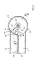
- the heat generator shown in the drawinghas a burner 1, to which a gas / air mixture is supplied via a main line 2, 2 ⁇ .
- the burner 1is located within a boiler housing 3, which also encloses the heat exchanger 4 of a heating system.
- the boiler housing 3is provided with a vent 5 for the flue gases, in which there is a fan 7 driven by a motor 6.
Landscapes
- Engineering & Computer Science (AREA)
- Chemical & Material Sciences (AREA)
- Combustion & Propulsion (AREA)
- Mechanical Engineering (AREA)
- General Engineering & Computer Science (AREA)
- Feeding And Controlling Fuel (AREA)
- Regulation And Control Of Combustion (AREA)
- Magnetically Actuated Valves (AREA)
- Compressor (AREA)
- Fuel-Injection Apparatus (AREA)
Abstract
Description
Translated fromGermanDie Erfindung betrifft eine Ventilanordnung zum wahlweisen Zuschalten und Absperren einer Nebenleitung, die in einer ein Brennstoff/Luft-Gemisch geregelter Zusammensetzung führenden Hauptleitung eines brennstoffbefeuerten Wärmeerzeugers mündet, und einer der Nebenleitung zugeordneten Brennstoffleitung, über die eine dem Luftdurchsatz in der Nebenleitung proportionale, zeitlich konstante Brennstoffmenge zugeführt wird, die dem Brennstoff/Luft-Verhältnis in dem in der Hauptleitung geführten Gemisch entspricht.The invention relates to a valve arrangement for selectively switching on and shutting off a secondary line, which opens into a main line of a fuel-fired heat generator carrying a fuel / air mixture controlled composition, and a fuel line assigned to the secondary line, via which a time constant is proportional to the air flow rate in the secondary line Amount of fuel is supplied, which corresponds to the fuel / air ratio in the mixture carried in the main line.
In der deutschen Patentanmeldung P 37 00 084.5-35, deren Inhalt als Stand der Technik gilt, ist eine Einrichtung zur Leistungsregelung von brennstoffbefeuerten, insbesondere gasbefeuerten Wärmeerzeugern beschrieben, bei dem dem Wärmeerzeuger über eine Hauptleitung ein Brennstoff/Luft-Gemisch zugeführt wird, dessen Zusammensetzung dadurch geregelt wird, daß der Hauptleitung eine vorgegebene, zeitlich konstante Brennstoffmenge zugeführt wird und der Luftdurchsatz in der Hauptleitung mittels eines Gebläses eingestellt wird, dessen Förderleistung in Abhängigkeit von dem Ausgangssignal eines in der Hauptleitung angeordneten Strömungssensors und ggf. weiteren, das optimale Brennstoff/Luft-Verhältnis beeinflussenden Größen mittels einer Regeleinrichtung gesteuert wird. Das über die Hauptleitung einem Brenner zugeführte Brennstoff/Luft-Gemisch bestimmt demnach die minimale Leistung des Wärmeerzeugers. Die bekannte Einrichtung weist zusätzlich mindestens eine Nebenleitung auf, über die eine zusätzliche Menge Brennstoff/Luft-Gemisch zugeführt werden kann. Da auch bei Zuschalten der Nebenleitung die Strömungsgeschwindigkeit der Luft in der Hauptleitung durch Erhöhen der Förderleistung des Gebläses konstant gehalten wird, wird durch die Nebenleitung eine Luftmenge gefördert, die sich zu der durch die Hauptleitung geförderten Luftmenge ebenso verhält wie der Querschnitt der Nebenleitung zum Querschnitt der Hauptleitung. Demgemäß kann auch der Nebenleitung eine konstante Brennstoffmenge zugeführt werden, die sich zu der der Hauptleitung zugeführten Brennstoffmenge ebenso verhält wie die Querschnitte der Leitungen. Dabei ist es auch möglich, die Heizleistung schrittweise oder stetig zu erhöhen, indem die Querschnitte der Nebenleitung und der zugeordneten Brennstoffleitung schrittweise oder stetig und zueinander proportional verändert werden. Bei der in der Patentanmeldung P 37 00 084.5 beschriebenen Anlage sind zu diesem Zweck in der Nebenleitung und der zugeordneten Brennstoffleitung motorisch verstellbare Absperrventile vorgesehen.German
Der Erfindung liegt die Aufgabe zugrunde, eine Ventilanordnung zu schaffen, die das gleichzeitige Zuschalten bzw. Absperren einer Nebenleitung und der ihr zugeordneten Brennstoffleitung gestattet und sich durch einfachen Aufbau und zugleich hohe Zuverlässigkeit auszeichnet, so daß sie auch für den Einsatz bei Wärmeerzeugern relativ kleiner Leistung eingesetzt werden kann und damit solche Wärmeerzeuger auch für den Einsatz auf Gebieten mit relativ geringem Wärmebedarf, wie beispielsweise in Heizungsanlagen für Einfamilienhäuser oder gar Etagenwohnungen, geeignet macht.The invention has for its object to provide a valve assembly that allows the simultaneous connection or shutdown of a secondary line and the fuel line assigned to it and is characterized by simple structure and high reliability, so that they are also for use in heat generators of relatively low power can be used and thus makes such heat generators suitable for use in areas with relatively low heat requirements, such as in heating systems for single-family homes or even flats.
Diese Aufgabe wird nach der Erfindung dadurch gelöst, daß die Nebenleitung und die Brennstoffleitung nebeneinander in die Hauptleitung münden und den Mündungen der beiden Leitungen ein gemeinsamer Schieber zugeordnet ist, der wahlweise in eine die beiden Mündungen gleichzeitig freigebende oder abdeckende Stellung bringbar ist.This object is achieved according to the invention in that the secondary line and the fuel line open side by side into the main line and the mouths of the two lines are assigned a common slide which can be brought into a position that simultaneously releases or covers the two mouths.
Bei Anwendung der erfindungsgemäßen Ventilanordnung entfällt die Notwendigkeit, sowohl in die Nebenleitung als auch in die zugeordnete Brennstoffleitung gesonderte Ventile einzubauen und ggf. mit einem gemeinsamen Antrieb zu verbinden und außerdem besondere Armaturen wie T-Stücke o. dgl. vorzusehen, um die Brennstoffleitung mit der Nebenleitung und dann die Nebenleitung mit der Hauptleitung zusammenzuführen, da die erfindungsgemäße Ventilanordnung sowohl die Funktionen zweier Absperrventile als auch der Leitungs-Zusammenführungen erfüllt. Außerdem besteht auch keine Notwendigkeit mehr, zwei getrennte Ventile an einen gemeinsamen Antrieb anzuschließen. Daher ermöglicht die erfindungsgemäße Ventilanordnung eine bedeutende Vereinfachung des Aufbaus und einer Verminderung des Platzbedarfes von brennstoffbefeuerten Wärmeerzeugern der beschriebenen Art. Der Wegfall von Einrichtungen zum Koppeln zweier getrennter Ventile erhöht zugleich die Betriebssicherheit und Zuverlässigkeit eines solchen Wärmeerzeugers.When using the valve arrangement according to the invention, there is no need to install separate valves both in the secondary line and in the associated fuel line and, if necessary, to connect them to a common drive and also to provide special fittings such as T-pieces or the like in order to connect the fuel line with the Merging the secondary line and then the secondary line with the main line, since the valve arrangement according to the invention fulfills both the functions of two shut-off valves and the line mergers. In addition, there is no longer any need to connect two separate valves to a common actuator. Therefore, the Valve arrangement according to the invention a significant simplification of the structure and a reduction in the space requirement of fuel-fired heat generators of the type described. The elimination of devices for coupling two separate valves simultaneously increases the operational safety and reliability of such a heat generator.
Die Anwendung der erfindungsgemäßen Ventilanordnung ist dann von besonderem Vorteil, wenn nicht nur eine sprunghafte Erhöhung der Heizleistung durch vollständiges Zuschalten der Nebenleitung und der zugeordneten Brennstoffleitung gewünscht wird, sondern eine mehr oder weniger stetige Änderung der Heizleistung, weil in weiterer Ausgestaltung der Erfindung die Mündungen der Nebenleitung und der Brennstoffleitung zueinander proportionale Querschnitte haben und der Schieber in Zwischenstellungen bringbar sein kann, in denen er gleiche Anteile der Mündungsquerschnitte freigibt bzw. abdeckt. Da der Durchsatz der über die Nebenleitung zugeführten Luft wie auch des über die Brennstoffleitung zugeführten Brennstoffes dem Mündungsquerschnitt proportional ist, kann durch Verändern der Mündungsquerschnitte die zusätzlich zu dem von der Hauptleitung geförderten Brennstoff/Luft-Gemisch zugeführte Menge eines solchen Gemisches mehr oder weniger stetig verändert werden. Bei einer bevorzugten Ausführungsform der Erfindung ist der Schieber schrittweise verstellbar, und es wird die Mündung der Brennstoffleitung von einer Anzahl Bohrungen gebildet, von denen bei jedem Schritt der Schieberverstellung eine freigegeben bzw. abgedeckt wird. Hat die Mündung der Nebenleitung einen rechteckigen Querschnitt, so ist der Durchsatz der Nebenleitung dem Stellweg des Schiebers genau proportional. Dabei kann dann entweder die Mündung der zugeordneten Brennstoffleitung ebenfalls einen rechteckigen Querschnitt haben oder es können bei der Verwendung von Bohrungen alle Bohrungen den gleichen Durchmesser haben.The application of the valve arrangement according to the invention is particularly advantageous if not only a sudden increase in the heating power by completely switching on the secondary line and the associated fuel line is desired, but a more or less constant change in the heating power, because in a further embodiment of the invention the mouths of the The secondary line and the fuel line have cross sections which are proportional to one another and the slide can be able to be brought into intermediate positions in which it releases or covers equal parts of the orifice cross sections. Since the throughput of the air supplied via the secondary line as well as of the fuel supplied via the fuel line is proportional to the cross-section of the mouth, the amount of such a mixture supplied in addition to the fuel / air mixture conveyed by the main line can be changed more or less continuously by changing the cross-sections of the mouth will. In a preferred embodiment of the invention, the slide is adjustable step by step, and the mouth of the fuel line is formed by a number of bores, one of which is released or covered at each step of the slide adjustment. If the mouth of the secondary line has a rectangular cross-section, the throughput of the secondary line is exactly proportional to the travel of the slide. Then either the mouth of the assigned fuel line also have a rectangular cross-section or it can all holes have the same diameter when using holes.
Für den mechanischen Aufbau einer solchen Ventilanordnung ist es von besonderem Vorteil, wenn die Hauptleitung an der Stelle der Einmündung der Nebenleitung eine Kammer mit einem kreisbogenförmigen Wandabschnitt bildet und der Schieber als Drehschieber ausgebildet ist. Drehschieberanordnungen sind besonders leicht herstellbar und gestatten eine einfache Lagerung sowie auch einen besonders einfachen Antrieb des Schiebers. Dabei kann dann die Brennstoffleitung innerhalb des durch die Mündung der Nebenleitung definierten Sektors der Kammer in einem zu dem kreisbogenförmigen Wandabschnitt senkrechten, ebenen Boden münden und der Schieber einen am Boden anliegenden, gefederten Einsatz aufweisen. Auch diese Gestaltung führt wieder zu einem besonders einfachen und raumsparenden Aufbau. Dabei kann die Kammer in besonders einfacher Weise vollständig von einem zylindrischen, an einem Ende offenen Topf gebildet werden, in dessen Mantel außer der Nebenleitung auch der zu einer Lufteintrittsöffnung führende Abschnitt der Hauptleitung mündet, während der zum Brenner des Wärmeerzeugers führende Abschnitt der Hauptleitung sich an das offene Ende des Topfes anschließt. Eine besonders raumsparende Anordnung ergibt sich dann, wenn sowohl der in den Mantel der Kammer mündende Abschnitt der Hauptleitung als auch die Nebenleitung von im Querschnitt rechteckigen Rohrabschnitten gebildet werden und diese Rohrabschnitte mit einer Seite aneinander anliegen.For the mechanical construction of such a valve arrangement, it is particularly advantageous if the main line forms a chamber with an arcuate wall section at the point where the secondary line opens and the slide is designed as a rotary slide valve. Rotary slide valve arrangements are particularly easy to manufacture and allow simple storage and also particularly simple drive of the slide valve. The fuel line can then open within the sector of the chamber defined by the mouth of the secondary line in a flat floor perpendicular to the wall section in the form of a circular arc, and the slide can have a spring-loaded insert resting on the floor. This design also leads to a particularly simple and space-saving construction. The chamber can be formed in a particularly simple manner completely by a cylindrical pot which is open at one end, into the jacket of which, in addition to the secondary line, the section of the main line leading to an air inlet opening also opens, while the section of the main line leading to the burner of the heat generator is attached connects the open end of the pot. A particularly space-saving arrangement is obtained if both the section of the main line opening into the jacket of the chamber and the secondary line are formed by pipe sections with a rectangular cross section and these pipe sections abut one side.
Eine weitere Vereinfachung der mittels einer solchen Ventilanordnung versehenen Anlage zur Wärmeerzeugung wird erzielt, wenn in weiterer Ausgestaltung der Erfindung in den Topf des Bodens auch de Brennstoffleitung mündet, die die zur Bildung des von der Hauptleitung geführten Brennstoff/Luft-Gemisches erforderliche Brennstoffmenge zuführt. Es ist dann nicht mehr die Installation besonderer Brennstoffleitungen für die Hauptleitung und die Nebenleitung erforderlich, sondern es kann eine einsame Brennstoffleitung verwendet werden, die an den Topf angeschlossen ist und mit Öffnungen in den Topf mündet, von denen eine, nicht abdeckbare Öffnung den Gasdurchsatz für die von der Hauptleitung geforderte Luftmenge bestimmt, wogegen eine oder mehrere andere Öffnungen der Nebenleitung zugeordnet sind und ebenso wie die Mündungsöffnung der Nebenleitung wahlweise durch den Schieber abgedeckt oder freigegeben werden können. So kann insbesondere der Boden des Topfes von einer Scheibe gebildet werden, in der sich ein Ringkanal befindet, an den eine gemeinsame Brennstoffleitung angeschlossen ist und der durch Öffnungen mit dem Inneren des Topfes verbunden ist, welche die Mündungen der der Nebenleitung sowie der Hauptleitung zugeordneten Brennstoffleitungen bilden.A further simplification of the system provided by means of such a valve arrangement for heat generation is achieved if, in a further embodiment of the invention, in the pot of Bottom also de fuel line opens, which supplies the amount of fuel required to form the fuel / air mixture led by the main line. It is then no longer necessary to install special fuel lines for the main line and the secondary line, but a lonely fuel line can be used, which is connected to the pot and opens into the pot with openings, one of which, which cannot be covered, opens the gas throughput for determines the amount of air required by the main line, whereas one or more other openings are assigned to the secondary line and, like the mouth opening of the secondary line, can optionally be covered or released by the slide. In particular, the bottom of the pot can be formed by a disk in which there is an annular channel to which a common fuel line is connected and which is connected to the interior of the pot through openings which connect the mouths of the fuel lines assigned to the secondary line and the main line form.
Bei dieser Ausführungsform der Erfindung gestattet der Boden der Kammer zugleich das Lagern einer gegenüber dem Boden abgedichteten Welle, an der im Inneren der Kammer der Schieber befestigt ist und deren den Boden durchdringendes Ende mit einem Antriebsmotor verbunden ist.In this embodiment of the invention, the bottom of the chamber also permits the bearing of a shaft which is sealed off from the bottom and to which the slide is fastened inside the chamber and whose end penetrating the bottom is connected to a drive motor.
Die Erfindung wird im folgenden anhand des in der Zeichnung dargestellten Ausführungsbeispieles näher beschrieben und erläutert. Die der Beschreibung und der Zeichnung zu entnehmenden Merkmale können bei anderen Ausführungsformen der Erfindung einzeln für sich oder zu mehreren in beliebiger Kombination Anwendung finden. Es zeigen
- Fig. 1 eine schematische Darstellung eines Wärmeerzeugers mit einer Ventilanordnung nach der Erfindung in schematischer Darstellung,
- Fig. 2 einen Schnitt längs der Linie II-II durch eine Ausführungsform der in Fig. 1 nur schematisch dargestellte Ventilanordnung und
- Fig. 3 einen Schnitt längs der Linie III-III durch die Ventilanordnung nach Fig. 2.
- 1 is a schematic representation of a heat generator with a valve arrangement according to the invention in a schematic representation,
- Fig. 2 shows a section along the line II-II through an embodiment of the valve arrangement shown only schematically in Fig. 1 and
- 3 shows a section along the line III-III through the valve arrangement according to FIG. 2.
Der in der Zeichnung dargestellte Wärmeerzeuger weist einen Brenner 1 auf, dem über eine Hauptleitung 2, 2ʹ ein Gas/Luft-Gemisch zugeführt wird. Der Brenner 1 befindet sich innerhalb eines Kesselgehäuses 3, das auch den Wärmeaustauscher 4 einer Heizungsanlage umschließt. Das Kesselgehäuse 3 ist mit einem Abzug 5 für die Rauchgase versehen, in dem sich ein von einem Motor 6 angetriebenes Gebläse 7 befindet.The heat generator shown in the drawing has a burner 1, to which a gas / air mixture is supplied via a
Die Hauptleitung 2, 2ʹ verbindet den Brenner 1 mit einer Lufteintrittsöffnung 8. In den Abschnitt 2 der Hauptleitung ragen weiterhin ein Temperatursensor 9 und ein Strömungssensor 10 hinein. Die Ausgangssignale dieser Sensoren 9, 10 werden einer Regeleinrichtung 11 zugeführt. Im Bereich zwischen den Sensoren 9, 10 und dem Brenner 1 mündet in die Hauptleitung 2 eine Brennstoffleitung 13, die der Hauptleitung als Brennstoff Gas zuführt. In der Brennstoffleitung 13 befinden sich in der Strömungsrichtung des Gases hintereinander ein Gasdruckregler 14, so daß der Hauptleitung 2, 2ʹ das Gas mit vorgegebenem Druck und daher auch vorgegebener Menge zugeführt wird. Um optimale Verbrennungsverhältnisse zu haben, gehört zu der vorgegebenen Gasmenge eine genau bestimmte Luftmenge. Die Zufuhr der richtigen Luftmenge wird durch den Strömungssensor 10 überwacht, dessen Ausgangssignal für die Strömungsgeschwindigkeit der Luft in dem Abschnitt 2 der Hauptleitung charakteristisch ist. Die Regeleinrichtung 11 steuert in Abhängigkeit von den Ausgangssignalen des Temperatursensors 9 und des Strömungssensors 10 die Drehzahl des zum Antrieb des Gebläses 7 dienenden Motors 6 in solcher Weise, daß in dem Abschnitt 2 der Hauptleitung die zur Zufuhr der richtigen Luftmenge erforderliche Strömungsgeschwindigkeit herrscht. Damit ist auf sehr einfache Weise gewährleistet, daß optimale Verbrennungsbedingungen für das dem Brenner 1 zugeführte Gas vorliegen.The
Der Hauptleitung 2, 2ʹ ist eine Nebenleitung 21 parallel geschaltet, die in die Hauptleitung 2, 2ʹ im Bereich zwischen den Sensoren 9, 10 und dem Brenner 1 mündet. Ähnlich wie die Hauptleitung 2, 2ʹ hat auch die Nebenleitung 21 ein als Lufteintrittsöffnung 22 dienendes, offenes Ende, und es ist auch ihr eine Brennstoffleitung 23 zugeordnet, die von der in die Hauptleitung 2, 2ʹ mündenden Brennstoffleitung 13 abzweigt. In dieser Brennstoffleitung 23 befindet sich ein Absperrventil 24. Auch in der Nebenleitung 21 befindet sich ein Absperrventil 25. Die Absperrventile 24 und 25 sind mit einem gemeinsamen Stellmotor 26 verbunden der bei Bedarf das gemeinsame Öffnen bzw. Schließen der Absperrventile 24, 25 bewirkt.The
Wie aus den Fig. 2 und 3 näher ersichtlich, sind die in Fig. 1 schematisch dargestellten Sperrventile 24, 25 für die Nebenleitung 21 und die zugeordnete Brennstoffleitung 23 in eine Ventilanordnung integriert, die einen zylindrischen Topf 31 aufweist, in dessen Mantel 32 der zur Lufteintrittsöffnung 8 führende Abschnitt 2 der Hauptleitung und die Nebenleitung 21 münden. Wie ersichtlich, haben beide Leitungen bei dem dargestellten Ausführungsbeispiel den gleichen rechteckigen Querschnitt und sind derart parallel zueinander angeordnet, daß sie mit einer Seite 27 bzw. 28 aneinander anliegen. Der zum Brenner 1 führende Abschnitt 2ʹ der Hauptleitung schließt an das offene Ende des Topfes 31 an.As can be seen from FIGS. 2 and 3 in more detail, the
Das dem Abschnitt 2ʹ der Hauptleitung gegenüberliegende Ende des Topfes 31 ist mit einem Boden 33 versehen, in den ein Ringkanal 34 eingearbeitet ist. Zu diesem Zweck besteht der Boden 33 aus zwei scheibenförmigen Teilen 35, 36, von denen der obere Teil 36 an seiner dem unteren Teil 35 zugewandten Seite eine den Ringkanal 34 bildende Nut aufweist. Der untere scheibenförmige Teil 35 ist mit einem Schraubanschluß für die Gasleitung 13 versehen, so daß die Gasleitung 13 in den Ringkanal 34 mündet. Dieser Ringkanal 34 steht mit dem Innenraum des Topfes 31 über Bohrungen 37 und 38 in Verbindung, von denen die Bohrung 37 vor der Mündung des Abschnittes 2 der Hauptleitung angeordnet ist und einen solchen Durchmesser hat, daß die über diese Bohrung 37 in den Topf eintretende Gasmenge der Mindestleistung des Brenners entspricht, auf welche die die Hauptleitung 2, 2ʹ durchströmende Luftmenge mittels der Sensoren 9, 10 eingestellt wird.The section 2ʹ of the main line opposite end of the
Die Bohrungen 38 sind innerhalb des in Fig. 2 durch strichpunktierte Linien begrenzten Sektors 39, der durch die Mündung 40 der Nebenleitung 21 im Mantel 32 des Topfes 31 definiert wird, und nebeneinander auf einem ebenfalls strichpunktiert angedeuteten Kreisbogen 41 angeordnet. Die Bohrungen 38 bilden in ihrer Gesamtheit die der Nebenleitung 21 zugeordnete Brennstoffleitung 23. Der Gesamtquerschnitt dieser Bohrungen 38 ist so bemessen, daß die über diese Bohrungen dem Topf 31 zugeführte Gasmenge zu der über die Nebenleitung 21 zugeführten Luftmenge in dem gleichen Verhältnis steht wie die über die Bohrung 37 zugeführte Gasmenge zu der durch den Abschnitt 2 der Hauptleitung zugeführten Luftmenge. Dabei können die über die Gesamtheit der Bohrungen 38 zugeführte Gasmenge und die über die Nebenleitung 21 zugeführte, entsprechende Luftmenge so bemessen sein, daß zusammen mit dem von der Hauptleitung 2, 2ʹ stets geführten Brennstoff/Luft-Gemisch die Maximalleistung des Brenners 1 erreicht wird. Bei dem dargestellten Ausführungsbeispiel haben der zur Lufteintrittsöffnung 8 führende Abschnitt 2 der Hauptleitung und die Nebenleitung 21 den gleichen Querschnitt, so daß auch die Gesamtheit der Bohrungen 38 den gleichen Querschnitt hat wie die Bohrung 37 und die Heizleistung des Brenners 1 durch Zuschalten der Nebenleitung 21 verdoppelt werden kann.The
Als Absperrventile 24, 25 für die Nebenleitung 21 und die zugeordnete Gasleitung 23 dient bei dem dargestellten Ausführungsbeispiel der Ventilanordnung ein Drehschieber 51, der auf dem inneren Ende einer in dem Boden 33 drehbar gelagerten und in nicht näher dargestellter Weise gegenüber dem Boden abgedichteten Welle 52 befestigt ist. Dieser Drehschieber weist an seinem Ende eine im Querschnitt kreisbogenförmige Platte 53 auf, die in einer ersten Endstellung die Mündung 40 der Nebenleitung 21 abdeckt und damit die Nebenleitung 21 absperrt. In seinem die Platte 53 mit der Welle 52 verbindenden Abschnitt weist der Drehschieber 51 eine zum Boden 33 des Topfes senkreche Bohrung 54 auf, in der ein stempelartiger Einsatz 55 verschiebbar gelagert und durch eine in der Bohrung 54 angeordnete Schraubendruckfeder 56 belastet ist, so daß dieser Einsatz mit der Außenfläche seines Kopfes 57 am Boden 33 anliegt. Der Durchmesser des Kopfes 57 ist so bemessen, daß er die auf dem Kreis bogen 41 angeordneten Bohrungen 38 vollständig abdeckt, wenn die Platte 53 die Mündung 40 der Nebenleitung 21 abdeckt. Durch Verschwenken des Drehschiebers 51 um einen Winkel, der im wesentlichen gleich dem Winkel des durch die Mündung 40 der Nebenleitung 21 definierten Sektors 39 gleich ist, kann der Drehschieber 51 in eine in der Zeichnung nicht dargestellte, zweite Endstellung gebracht werden, in welcher die Platte 53 die Mündung 40 und ebenso auch der Kopf 57 des Einsatzes 55 sämtliche Bohrungen 38 freigibt. Nimmt der Drehschieber eine zwischen diesen beiden Endstellungen liegende Stellung ein, wird die Mündung 40 der Nebenleitung 21 nur partiell freigegeben. Die Verwendung von Rohren mit rechteckigem Querschnitt hat zur Folge, daß auch die Mündung 40 der Nebenleitung einen rechteckigen Querschnitt hat und der freigegebene Abschnitt der Nebenleitung dem Schwenkwinkel des Drehschiebers genau proportional ist. Ebenso ist durch die Anwendung einer Anzahl von Bohrungen 38 als Mündung der der Nebenleitung 21 zugeordneten Brennstoffleitung gewährleistet, daß die zugeführte Gasmenge der Anzahl der freigegebenen Bohrungen und damit wiederum dem Schwenkwinkel des Drehschiebers proportional ist. Dabei ist es zweckmäßig, den Drehschieber schrittweise so zu verstellen, daß jeweils eine weitere Bohrung vollständig freigegeben oder abgedeckt wird. Wenn eine völlig stetige Veränderung der Heizleistung gewünscht wird, könnte die Reihe von Bohrungen durch einen entsprechenden Schlitz ersetzt werden. Ebenso wäre es möglich, eine größere Bohrung ähnlich wie die Mündung der Nebenleitung partiell abzudecken, wobei dann eine solche Bohrung einer kreisförmigen Mündung der Nebenleitung entsprechen wurde. Im Hinblick auf eine lineare Abhängigkeit der Leistungsänderung vom Drehwinkel wird jedoch die beschriebene Ausführungsform mit einer rechteckigen Mündung der Nebenleitung und einer entsprechend gestalteten Mündung der zugeordneten Brennstoffleitung bevorzugt.In the exemplary embodiment of the valve arrangement shown, a
Der besondere Vorteil der Erfindung besteht darin, daß durch die Verwendung eines gemeinsamen Schiebers zum Freigeben oder Absperren der Nebenleitung sowie der zugeordneten Brennstoffleitung keinerlei Probleme für den motorischen Antrieb der Ventilanordnung bestehen. Bei dem dargestellten Ausführungsbeispiel ist der Antriebsmotor 26 für den Drehschieber 51, der den beiden Absperrventilen 24, 25 nach Fig. 1 entspricht, mittels einer Halterung 61 an dem Boden 33 des Topfes 31 derart befestigt, daß die Abtriebswelle 62 des Motors mit der den Drehschieber 51 tragenden Welle 52 fluchtet und mit dieser Welle durch eine Steckkupplung 63 verbunden werden kann. Bei dem Motor 26 kann es sich um einen Schrittschaltmotor, aber auch um einen kontinuierlich laufenden Motor mit entsprechender Steuerung handeln, der vorzugsweise eine starke Untersetzung aufweist, da der Drehschieber 51 nur mit relativ geringer Geschwindigkeit verstellt werden darf. Da der Luftdurchsatz durch die Förderleistung des Gebläses 7 bestimmt wird, darf die Veränderung der Leitunsquerschnitte und damit der Brennstoffzufuhr nicht schneller erfolgen als mit der Geschwindigkeit, mit der das Gebläse 7 auf den veränderten Luftbedarf reagieren kann.The particular advantage of the invention is that by using a common slide for releasing or shutting off the secondary line and the associated fuel line there are no problems for the motor drive of the valve arrangement. In the illustrated embodiment, the
Es versteht sich, daß die Erfindung nicht auf das dargestellte Ausführungsbeispiel beschränkt ist, sondern Abweichungen davon möglich sind, ohne den Rahmen der Erfindung zu verlassen. So ist beispielsweise ohne weiteres ersichtlich, daß die zylindrische Form des Topfes nur für den Schwenkbereich des Drehschiebers von Bedeutung ist, so daß selbst bei Verwendung eines Drehschiebers die von dem Topf gebildete Kammer auch eine andere Querschnittsform haben kann, solange nur die Nebenleitung in einen zylindrischen Wandabschnitt mündet und ausreichend Raum zum Wegschwenken des Drehschiebers vorhanden ist. Weiterhin ist ersichtlich, daß anstelle eines Drehschiebers auch ein geradlinig beweglicher Schieber Verwendung finden kann und daß es möglich ist, die Mündungen der Luft- und der Gasleitung in dem gleichen Wandabschnitt vorzusehen. Dabei besteht sowohl die Möglichkeit, diese Mündungen mit ausreichendem Abstand in der Bewegungsrichtung des Schiebers hintereinander als auch an der gleichen Wand senkrecht zur Bewegungsrichtung des Schiebers nebeneinander anzuordnen. Es sei auch erwähnt, daß bei Wärmeerzeugern, die eine solche Ventilanordnung aufweisen, das Gebläse an einem für die Hauptleitung und die Nebenleitung gemeinsamen Lufteinlaß angeordnet sein könnte. Angesichts all dieser vielen Möglichkeiten wird jedoch die dargestellte Ausführungsform der Ventilanordnung wegen ihrer besonders einfachen und kompakten Bauweise als optimale Verwirklichung der Erfindung angesehen.It is understood that the invention is not limited to the exemplary embodiment shown, but deviations from it are possible without leaving the scope of the invention. For example, it is readily apparent that the cylindrical shape of the pot is only important for the pivoting range of the rotary valve, so that even when using a rotary valve, the chamber formed by the pot is also different Can have a cross-sectional shape as long as only the secondary line opens into a cylindrical wall section and there is sufficient space for the rotary valve to pivot away. It can also be seen that instead of a rotary valve, a linearly movable valve can also be used and that it is possible to provide the mouths of the air and gas lines in the same wall section. There is the possibility of arranging these orifices one behind the other at a sufficient distance in the direction of movement of the slide and also on the same wall perpendicular to the direction of movement of the slide. It should also be mentioned that in the case of heat generators which have such a valve arrangement, the fan could be arranged at an air inlet common to the main line and the secondary line. In view of all these many possibilities, however, the illustrated embodiment of the valve arrangement is regarded as the optimal implementation of the invention because of its particularly simple and compact design.
Claims (11)
Translated fromGermandadurch gekennzeichnet,
daß die Nebenleitung (21) und die Brennstoffleitung (23) nebeneinander in die Hauptleitung (2, 2ʹ) münden und den Mündungen (40, 38) der beiden Leitungen ein gemeinsamer Schieber (51) zugeordnet ist, der wahlweise in eine die beiden Mündungen (40, 38) gleichzeitig freigebende oder abdeckende Stellung bringbar ist.1.Valve arrangement for selectively switching on and shutting off a secondary line, which opens into a main line of a fuel-fired heat generator carrying a fuel / air mixture of controlled composition, and a fuel line assigned to the secondary line, via which a fuel quantity proportional to the air flow rate in the secondary line is fed in over a period of time which corresponds to the fuel / air ratio in the mixture carried in the main line,
characterized,
that the secondary line (21) and the fuel line (23) open side by side into the main line (2, 2ʹ) and the mouths (40, 38) of the two lines is assigned a common slide (51), which optionally in one of the two mouths ( 40, 38) simultaneously releasing or covering position can be brought.
Priority Applications (1)
| Application Number | Priority Date | Filing Date | Title |
|---|---|---|---|
| AT88102493TATE68580T1 (en) | 1987-03-17 | 1988-02-20 | VALVE ARRANGEMENT. |
Applications Claiming Priority (2)
| Application Number | Priority Date | Filing Date | Title |
|---|---|---|---|
| DE19873708573DE3708573A1 (en) | 1987-03-17 | 1987-03-17 | VALVE ARRANGEMENT |
| DE3708573 | 1987-03-17 |
Publications (3)
| Publication Number | Publication Date |
|---|---|
| EP0282758A2true EP0282758A2 (en) | 1988-09-21 |
| EP0282758A3 EP0282758A3 (en) | 1988-12-14 |
| EP0282758B1 EP0282758B1 (en) | 1991-10-16 |
Family
ID=6323239
Family Applications (1)
| Application Number | Title | Priority Date | Filing Date |
|---|---|---|---|
| EP88102493AExpired - LifetimeEP0282758B1 (en) | 1987-03-17 | 1988-02-20 | Valve arrangement |
Country Status (3)
| Country | Link |
|---|---|
| EP (1) | EP0282758B1 (en) |
| AT (1) | ATE68580T1 (en) |
| DE (2) | DE3708573A1 (en) |
Cited By (17)
| Publication number | Priority date | Publication date | Assignee | Title |
|---|---|---|---|---|
| GB2317444B (en)* | 1996-09-06 | 2000-11-01 | Hepworth Heating Ltd | Control mechanisms for gas fires |
| US9645584B2 (en) | 2014-09-17 | 2017-05-09 | Honeywell International Inc. | Gas valve with electronic health monitoring |
| US9657946B2 (en) | 2012-09-15 | 2017-05-23 | Honeywell International Inc. | Burner control system |
| US9683674B2 (en) | 2013-10-29 | 2017-06-20 | Honeywell Technologies Sarl | Regulating device |
| US9835265B2 (en) | 2011-12-15 | 2017-12-05 | Honeywell International Inc. | Valve with actuator diagnostics |
| US9841122B2 (en) | 2014-09-09 | 2017-12-12 | Honeywell International Inc. | Gas valve with electronic valve proving system |
| US9846440B2 (en) | 2011-12-15 | 2017-12-19 | Honeywell International Inc. | Valve controller configured to estimate fuel comsumption |
| US9851103B2 (en) | 2011-12-15 | 2017-12-26 | Honeywell International Inc. | Gas valve with overpressure diagnostics |
| US9995486B2 (en) | 2011-12-15 | 2018-06-12 | Honeywell International Inc. | Gas valve with high/low gas pressure detection |
| US10024439B2 (en) | 2013-12-16 | 2018-07-17 | Honeywell International Inc. | Valve over-travel mechanism |
| US10422531B2 (en) | 2012-09-15 | 2019-09-24 | Honeywell International Inc. | System and approach for controlling a combustion chamber |
| US10503181B2 (en) | 2016-01-13 | 2019-12-10 | Honeywell International Inc. | Pressure regulator |
| WO2020030323A1 (en)* | 2018-08-09 | 2020-02-13 | Ebm-Papst Landshut Gmbh | Method for controlling a mixing ratio of fuel gas and air for a heating appliance |
| US10564062B2 (en) | 2016-10-19 | 2020-02-18 | Honeywell International Inc. | Human-machine interface for gas valve |
| US10697815B2 (en) | 2018-06-09 | 2020-06-30 | Honeywell International Inc. | System and methods for mitigating condensation in a sensor module |
| US10697632B2 (en) | 2011-12-15 | 2020-06-30 | Honeywell International Inc. | Gas valve with communication link |
| US11073281B2 (en) | 2017-12-29 | 2021-07-27 | Honeywell International Inc. | Closed-loop programming and control of a combustion appliance |
Families Citing this family (7)
| Publication number | Priority date | Publication date | Assignee | Title |
|---|---|---|---|---|
| DE3829664C1 (en)* | 1988-09-01 | 1990-01-18 | Karl Dungs Gmbh & Co, 7060 Schorndorf, De | |
| AT394051B (en)* | 1988-12-06 | 1992-01-27 | Greiner Schaumstoffwerk | MOLDED PART FROM INJECTED OR EXTRUDED PLASTIC SHEETS AND METHOD FOR THE PRODUCTION THEREOF |
| US8905063B2 (en) | 2011-12-15 | 2014-12-09 | Honeywell International Inc. | Gas valve with fuel rate monitor |
| US8899264B2 (en) | 2011-12-15 | 2014-12-02 | Honeywell International Inc. | Gas valve with electronic proof of closure system |
| US9074770B2 (en) | 2011-12-15 | 2015-07-07 | Honeywell International Inc. | Gas valve with electronic valve proving system |
| US8839815B2 (en) | 2011-12-15 | 2014-09-23 | Honeywell International Inc. | Gas valve with electronic cycle counter |
| US8947242B2 (en) | 2011-12-15 | 2015-02-03 | Honeywell International Inc. | Gas valve with valve leakage test |
Family Cites Families (7)
| Publication number | Priority date | Publication date | Assignee | Title |
|---|---|---|---|---|
| DE619637C (en)* | 1930-10-10 | 1935-10-04 | Selas Akt Ges | Mixing device for two gases, especially for fuel gas and air, in gas firing systems |
| US3212526A (en)* | 1963-04-29 | 1965-10-19 | Selas Corp Of America | Ratio adjusting mechanism for gas mixing machines |
| FR2325099A1 (en)* | 1975-09-18 | 1977-04-15 | Utilisation Ration Gaz | Mixture ratio regulation for two gaseous fluids - uses predetermined calibrated orifices to produce constant ratio independent of flow |
| DE3019622A1 (en)* | 1980-05-22 | 1981-11-26 | SIEMENS AG AAAAA, 1000 Berlin und 8000 München | METHOD FOR OPERATING A GASIFICATION BURNER / BOILER PLANT |
| DE3113511C2 (en)* | 1981-04-03 | 1986-07-10 | Holec Gas Generators B.V., Nijmegen | Burner device for a gaseous fuel |
| DE3526608A1 (en)* | 1985-07-25 | 1987-01-29 | Ruhrgas Ag | DEVICE FOR REGULATING THE AMOUNT AND / OR MIXING RATIO OF A COMBUSTION GAS-AIR MIXTURE |
| US4640678A (en)* | 1985-09-26 | 1987-02-03 | Joseph Fraioli | Dual-valve air-gas controller |
- 1987
- 1987-03-17DEDE19873708573patent/DE3708573A1/ennot_activeCeased
- 1988
- 1988-02-20DEDE8888102493Tpatent/DE3865467D1/ennot_activeExpired - Lifetime
- 1988-02-20ATAT88102493Tpatent/ATE68580T1/ennot_activeIP Right Cessation
- 1988-02-20EPEP88102493Apatent/EP0282758B1/ennot_activeExpired - Lifetime
Cited By (21)
| Publication number | Priority date | Publication date | Assignee | Title |
|---|---|---|---|---|
| GB2317444B (en)* | 1996-09-06 | 2000-11-01 | Hepworth Heating Ltd | Control mechanisms for gas fires |
| US10697632B2 (en) | 2011-12-15 | 2020-06-30 | Honeywell International Inc. | Gas valve with communication link |
| US9835265B2 (en) | 2011-12-15 | 2017-12-05 | Honeywell International Inc. | Valve with actuator diagnostics |
| US10851993B2 (en) | 2011-12-15 | 2020-12-01 | Honeywell International Inc. | Gas valve with overpressure diagnostics |
| US9846440B2 (en) | 2011-12-15 | 2017-12-19 | Honeywell International Inc. | Valve controller configured to estimate fuel comsumption |
| US9851103B2 (en) | 2011-12-15 | 2017-12-26 | Honeywell International Inc. | Gas valve with overpressure diagnostics |
| US9995486B2 (en) | 2011-12-15 | 2018-06-12 | Honeywell International Inc. | Gas valve with high/low gas pressure detection |
| US11421875B2 (en) | 2012-09-15 | 2022-08-23 | Honeywell International Inc. | Burner control system |
| US9657946B2 (en) | 2012-09-15 | 2017-05-23 | Honeywell International Inc. | Burner control system |
| US10422531B2 (en) | 2012-09-15 | 2019-09-24 | Honeywell International Inc. | System and approach for controlling a combustion chamber |
| US9683674B2 (en) | 2013-10-29 | 2017-06-20 | Honeywell Technologies Sarl | Regulating device |
| US10215291B2 (en) | 2013-10-29 | 2019-02-26 | Honeywell International Inc. | Regulating device |
| US10024439B2 (en) | 2013-12-16 | 2018-07-17 | Honeywell International Inc. | Valve over-travel mechanism |
| US9841122B2 (en) | 2014-09-09 | 2017-12-12 | Honeywell International Inc. | Gas valve with electronic valve proving system |
| US10203049B2 (en) | 2014-09-17 | 2019-02-12 | Honeywell International Inc. | Gas valve with electronic health monitoring |
| US9645584B2 (en) | 2014-09-17 | 2017-05-09 | Honeywell International Inc. | Gas valve with electronic health monitoring |
| US10503181B2 (en) | 2016-01-13 | 2019-12-10 | Honeywell International Inc. | Pressure regulator |
| US10564062B2 (en) | 2016-10-19 | 2020-02-18 | Honeywell International Inc. | Human-machine interface for gas valve |
| US11073281B2 (en) | 2017-12-29 | 2021-07-27 | Honeywell International Inc. | Closed-loop programming and control of a combustion appliance |
| US10697815B2 (en) | 2018-06-09 | 2020-06-30 | Honeywell International Inc. | System and methods for mitigating condensation in a sensor module |
| WO2020030323A1 (en)* | 2018-08-09 | 2020-02-13 | Ebm-Papst Landshut Gmbh | Method for controlling a mixing ratio of fuel gas and air for a heating appliance |
Also Published As
| Publication number | Publication date |
|---|---|
| DE3865467D1 (en) | 1991-11-21 |
| EP0282758A3 (en) | 1988-12-14 |
| EP0282758B1 (en) | 1991-10-16 |
| ATE68580T1 (en) | 1991-11-15 |
| DE3708573A1 (en) | 1988-09-29 |
Similar Documents
| Publication | Publication Date | Title |
|---|---|---|
| EP0282758B1 (en) | Valve arrangement | |
| EP0356690B1 (en) | Fuel-fired heat producer | |
| DE60129164T2 (en) | AIR GAS BLENDER | |
| DE2007226A1 (en) | Ventilation device, in particular for motor vehicles | |
| DE3850935T2 (en) | GAS / AIR RATIO CONTROL VALVE FOR GAS BURNERS. | |
| DE2454512B2 (en) | Exhaust gas recirculation device for internal combustion engines | |
| DD294770A5 (en) | DEVICE FOR REGULATING A VOLUME FLOW IN A GUIDE TUBE | |
| DE3211962A1 (en) | METHOD AND DEVICE FOR REGULATING FLAPS OF A VENTILATION AND TEMPERATURE CONTROL SYSTEM FOR A VEHICLE | |
| DE2428895C3 (en) | Closing device for air outlet openings | |
| DE3510009A1 (en) | Mixer tap for mixing hot and cold water | |
| DE4416154A1 (en) | Through-flow regulator valve with partition wall + | |
| DE4117445C2 (en) | Valve for controlling or regulating the flow of a fluid | |
| EP0210472B1 (en) | Device for controlling the flow rate and/or the mixing ratio of a combustible gas-air mixture | |
| DE3907631C2 (en) | Volume flow control system for lubrication systems | |
| DE2346895A1 (en) | CARBURETOR | |
| DE4407758C2 (en) | Atmospheric premix gas burner | |
| DE19703082A1 (en) | Through-flow regulator for sick-child incubator system | |
| DE954750C (en) | Carburettor with auxiliary starting device | |
| DE2432675B2 (en) | Control valve | |
| DE3438803A1 (en) | FLUID DISTRIBUTOR FOR CONTROLLING AN ACTUATING CYLINDER FOR STEP-BY-STEP SHIFTING AND HEATING OR AIR-CONDITIONING DEVICE FOR MOTOR VEHICLES, WHICH INCLUDE SUCH A DISTRIBUTOR | |
| DE4316315A1 (en) | Burner | |
| EP0341604B1 (en) | Piston valve | |
| DE3205984C2 (en) | Valve device for metering the flow rates of fuel-rich gases in ramjet rocket engines | |
| DE69411416T2 (en) | Valve arrangement for regulating a gas flow | |
| DE1222197B (en) | Thermostat regulator for regulating the fuel supply to a burner device |
Legal Events
| Date | Code | Title | Description |
|---|---|---|---|
| PUAI | Public reference made under article 153(3) epc to a published international application that has entered the european phase | Free format text:ORIGINAL CODE: 0009012 | |
| AK | Designated contracting states | Kind code of ref document:A2 Designated state(s):AT BE CH DE FR GB IT LI NL | |
| PUAL | Search report despatched | Free format text:ORIGINAL CODE: 0009013 | |
| AK | Designated contracting states | Kind code of ref document:A3 Designated state(s):AT BE CH DE FR GB IT LI NL | |
| 17P | Request for examination filed | Effective date:19881201 | |
| 17Q | First examination report despatched | Effective date:19910218 | |
| GRAA | (expected) grant | Free format text:ORIGINAL CODE: 0009210 | |
| AK | Designated contracting states | Kind code of ref document:B1 Designated state(s):AT BE CH DE FR GB IT LI NL | |
| REF | Corresponds to: | Ref document number:68580 Country of ref document:AT Date of ref document:19911115 Kind code of ref document:T | |
| REF | Corresponds to: | Ref document number:3865467 Country of ref document:DE Date of ref document:19911121 | |
| ITF | It: translation for a ep patent filed | ||
| GBT | Gb: translation of ep patent filed (gb section 77(6)(a)/1977) | ||
| ET | Fr: translation filed | ||
| PLBE | No opposition filed within time limit | Free format text:ORIGINAL CODE: 0009261 | |
| STAA | Information on the status of an ep patent application or granted ep patent | Free format text:STATUS: NO OPPOSITION FILED WITHIN TIME LIMIT | |
| 26N | No opposition filed | ||
| PGFP | Annual fee paid to national office [announced via postgrant information from national office to epo] | Ref country code:DE Payment date:19991229 Year of fee payment:13 | |
| PGFP | Annual fee paid to national office [announced via postgrant information from national office to epo] | Ref country code:GB Payment date:20000128 Year of fee payment:13 | |
| PGFP | Annual fee paid to national office [announced via postgrant information from national office to epo] | Ref country code:FR Payment date:20000217 Year of fee payment:13 | |
| PGFP | Annual fee paid to national office [announced via postgrant information from national office to epo] | Ref country code:BE Payment date:20000218 Year of fee payment:13 | |
| PGFP | Annual fee paid to national office [announced via postgrant information from national office to epo] | Ref country code:NL Payment date:20000223 Year of fee payment:13 | |
| PGFP | Annual fee paid to national office [announced via postgrant information from national office to epo] | Ref country code:AT Payment date:20000225 Year of fee payment:13 | |
| PGFP | Annual fee paid to national office [announced via postgrant information from national office to epo] | Ref country code:CH Payment date:20000504 Year of fee payment:13 | |
| PG25 | Lapsed in a contracting state [announced via postgrant information from national office to epo] | Ref country code:GB Free format text:LAPSE BECAUSE OF NON-PAYMENT OF DUE FEES Effective date:20010220 Ref country code:AT Free format text:LAPSE BECAUSE OF NON-PAYMENT OF DUE FEES Effective date:20010220 | |
| PG25 | Lapsed in a contracting state [announced via postgrant information from national office to epo] | Ref country code:LI Free format text:LAPSE BECAUSE OF NON-PAYMENT OF DUE FEES Effective date:20010228 Ref country code:CH Free format text:LAPSE BECAUSE OF NON-PAYMENT OF DUE FEES Effective date:20010228 Ref country code:BE Free format text:LAPSE BECAUSE OF NON-PAYMENT OF DUE FEES Effective date:20010228 | |
| BERE | Be: lapsed | Owner name:KARL DUNGS G.M.B.H. & CO. Effective date:20010228 | |
| PG25 | Lapsed in a contracting state [announced via postgrant information from national office to epo] | Ref country code:NL Free format text:LAPSE BECAUSE OF NON-PAYMENT OF DUE FEES Effective date:20010901 | |
| REG | Reference to a national code | Ref country code:CH Ref legal event code:PL | |
| GBPC | Gb: european patent ceased through non-payment of renewal fee | Effective date:20010220 | |
| PG25 | Lapsed in a contracting state [announced via postgrant information from national office to epo] | Ref country code:FR Free format text:LAPSE BECAUSE OF NON-PAYMENT OF DUE FEES Effective date:20011031 | |
| NLV4 | Nl: lapsed or anulled due to non-payment of the annual fee | Effective date:20010901 | |
| REG | Reference to a national code | Ref country code:FR Ref legal event code:ST | |
| PG25 | Lapsed in a contracting state [announced via postgrant information from national office to epo] | Ref country code:DE Free format text:LAPSE BECAUSE OF NON-PAYMENT OF DUE FEES Effective date:20011201 | |
| PG25 | Lapsed in a contracting state [announced via postgrant information from national office to epo] | Ref country code:IT Free format text:LAPSE BECAUSE OF NON-PAYMENT OF DUE FEES;WARNING: LAPSES OF ITALIAN PATENTS WITH EFFECTIVE DATE BEFORE 2007 MAY HAVE OCCURRED AT ANY TIME BEFORE 2007. THE CORRECT EFFECTIVE DATE MAY BE DIFFERENT FROM THE ONE RECORDED. Effective date:20050220 |