EP0281157A2 - Power system for inductively coupled plasma torch - Google Patents
Power system for inductively coupled plasma torchDownload PDFInfo
- Publication number
- EP0281157A2 EP0281157A2EP88103403AEP88103403AEP0281157A2EP 0281157 A2EP0281157 A2EP 0281157A2EP 88103403 AEP88103403 AEP 88103403AEP 88103403 AEP88103403 AEP 88103403AEP 0281157 A2EP0281157 A2EP 0281157A2
- Authority
- EP
- European Patent Office
- Prior art keywords
- power
- plasma
- voltage
- receptive
- output
- Prior art date
- Legal status (The legal status is an assumption and is not a legal conclusion. Google has not performed a legal analysis and makes no representation as to the accuracy of the status listed.)
- Granted
Links
- 238000009616inductively coupled plasmaMethods0.000titledescription11
- 230000006698inductionEffects0.000claimsabstractdescription39
- 230000008859changeEffects0.000claimsabstractdescription24
- 230000001351cycling effectEffects0.000claimsabstractdescription15
- 230000000694effectsEffects0.000claimsabstractdescription8
- 230000004044responseEffects0.000claimsabstractdescription8
- 239000000126substanceSubstances0.000claimsabstractdescription8
- 239000003990capacitorSubstances0.000claimsdescription23
- 230000008878couplingEffects0.000claimsdescription16
- 238000010168coupling processMethods0.000claimsdescription16
- 238000005859coupling reactionMethods0.000claimsdescription16
- 238000010304firingMethods0.000claimsdescription7
- XUIMIQQOPSSXEZ-UHFFFAOYSA-NSiliconChemical compound[Si]XUIMIQQOPSSXEZ-UHFFFAOYSA-N0.000claimsdescription4
- 229910052710siliconInorganic materials0.000claimsdescription4
- 239000010703siliconSubstances0.000claimsdescription4
- 238000012546transferMethods0.000claimsdescription4
- 238000004804windingMethods0.000claimsdescription4
- 230000007423decreaseEffects0.000claimsdescription2
- 238000007599dischargingMethods0.000claims2
- 239000013078crystalSubstances0.000abstractdescription7
- 230000000977initiatory effectEffects0.000abstract1
- 239000000523sampleSubstances0.000description22
- 239000007789gasSubstances0.000description18
- 101100365087Arabidopsis thaliana SCRA geneProteins0.000description4
- 101000668165Homo sapiens RNA-binding motif, single-stranded-interacting protein 1Proteins0.000description4
- 102100039692RNA-binding motif, single-stranded-interacting protein 1Human genes0.000description4
- 101150105073SCR1 geneProteins0.000description4
- 101100134054Saccharomyces cerevisiae (strain ATCC 204508 / S288c) NTG1 geneProteins0.000description4
- 230000033228biological regulationEffects0.000description4
- 239000012159carrier gasSubstances0.000description4
- 239000010453quartzSubstances0.000description4
- VYPSYNLAJGMNEJ-UHFFFAOYSA-Nsilicon dioxideInorganic materialsO=[Si]=OVYPSYNLAJGMNEJ-UHFFFAOYSA-N0.000description4
- 238000010586diagramMethods0.000description3
- 230000001939inductive effectEffects0.000description3
- 238000002347injectionMethods0.000description3
- 239000007924injectionSubstances0.000description3
- 239000000463materialSubstances0.000description3
- 239000002184metalSubstances0.000description3
- 229910052751metalInorganic materials0.000description3
- 239000000843powderSubstances0.000description3
- 230000001360synchronised effectEffects0.000description3
- XKRFYHLGVUSROY-UHFFFAOYSA-NArgonChemical compound[Ar]XKRFYHLGVUSROY-UHFFFAOYSA-N0.000description2
- IJGRMHOSHXDMSA-UHFFFAOYSA-NAtomic nitrogenChemical compoundN#NIJGRMHOSHXDMSA-UHFFFAOYSA-N0.000description2
- RYGMFSIKBFXOCR-UHFFFAOYSA-NCopperChemical compound[Cu]RYGMFSIKBFXOCR-UHFFFAOYSA-N0.000description2
- 238000013459approachMethods0.000description2
- 238000001816coolingMethods0.000description2
- 239000000112cooling gasSubstances0.000description2
- 229910052802copperInorganic materials0.000description2
- 239000010949copperSubstances0.000description2
- 238000010438heat treatmentMethods0.000description2
- 239000000203mixtureSubstances0.000description2
- 230000010363phase shiftEffects0.000description2
- 230000001105regulatory effectEffects0.000description2
- 230000000717retained effectEffects0.000description2
- 238000004611spectroscopical analysisMethods0.000description2
- 239000007858starting materialSubstances0.000description2
- OKTJSMMVPCPJKN-UHFFFAOYSA-NCarbonChemical compound[C]OKTJSMMVPCPJKN-UHFFFAOYSA-N0.000description1
- 239000004215Carbon black (E152)Substances0.000description1
- 239000003570airSubstances0.000description1
- PNEYBMLMFCGWSK-UHFFFAOYSA-Naluminium oxideInorganic materials[O-2].[O-2].[O-2].[Al+3].[Al+3]PNEYBMLMFCGWSK-UHFFFAOYSA-N0.000description1
- 238000004458analytical methodMethods0.000description1
- 229910052786argonInorganic materials0.000description1
- QVGXLLKOCUKJST-UHFFFAOYSA-Natomic oxygenChemical compound[O]QVGXLLKOCUKJST-UHFFFAOYSA-N0.000description1
- 230000004323axial lengthEffects0.000description1
- 230000004888barrier functionEffects0.000description1
- 230000015572biosynthetic processEffects0.000description1
- 229910052799carbonInorganic materials0.000description1
- 238000006243chemical reactionMethods0.000description1
- 230000003247decreasing effectEffects0.000description1
- 230000001419dependent effectEffects0.000description1
- 230000001066destructive effectEffects0.000description1
- 239000012777electrically insulating materialSubstances0.000description1
- 230000005669field effectEffects0.000description1
- 238000001914filtrationMethods0.000description1
- 239000001307heliumSubstances0.000description1
- 229910052734heliumInorganic materials0.000description1
- SWQJXJOGLNCZEY-UHFFFAOYSA-Nhelium atomChemical compound[He]SWQJXJOGLNCZEY-UHFFFAOYSA-N0.000description1
- 229930195733hydrocarbonNatural products0.000description1
- 150000002430hydrocarbonsChemical class0.000description1
- 239000001257hydrogenSubstances0.000description1
- 229910052739hydrogenInorganic materials0.000description1
- 125000004435hydrogen atomChemical class[H]*0.000description1
- 239000007788liquidSubstances0.000description1
- 238000012423maintenanceMethods0.000description1
- 230000007257malfunctionEffects0.000description1
- 238000002844meltingMethods0.000description1
- 230000008018meltingEffects0.000description1
- 238000012986modificationMethods0.000description1
- 230000004048modificationEffects0.000description1
- 229910052757nitrogenInorganic materials0.000description1
- 239000001301oxygenSubstances0.000description1
- 229910052760oxygenInorganic materials0.000description1
- 238000011084recoveryMethods0.000description1
- 238000005070samplingMethods0.000description1
- 230000000087stabilizing effectEffects0.000description1
- 238000012360testing methodMethods0.000description1
- 230000007704transitionEffects0.000description1
- XLYOFNOQVPJJNP-UHFFFAOYSA-NwaterSubstancesOXLYOFNOQVPJJNP-UHFFFAOYSA-N0.000description1
Images


Classifications
- H—ELECTRICITY
- H05—ELECTRIC TECHNIQUES NOT OTHERWISE PROVIDED FOR
- H05H—PLASMA TECHNIQUE; PRODUCTION OF ACCELERATED ELECTRICALLY-CHARGED PARTICLES OR OF NEUTRONS; PRODUCTION OR ACCELERATION OF NEUTRAL MOLECULAR OR ATOMIC BEAMS
- H05H1/00—Generating plasma; Handling plasma
- H05H1/24—Generating plasma
- H05H1/26—Plasma torches
- H05H1/30—Plasma torches using applied electromagnetic fields, e.g. high frequency or microwave energy
- H—ELECTRICITY
- H05—ELECTRIC TECHNIQUES NOT OTHERWISE PROVIDED FOR
- H05H—PLASMA TECHNIQUE; PRODUCTION OF ACCELERATED ELECTRICALLY-CHARGED PARTICLES OR OF NEUTRONS; PRODUCTION OR ACCELERATION OF NEUTRAL MOLECULAR OR ATOMIC BEAMS
- H05H1/00—Generating plasma; Handling plasma
- H05H1/24—Generating plasma
- H05H1/26—Plasma torches
- H05H1/32—Plasma torches using an arc
- H05H1/34—Details, e.g. electrodes, nozzles
- H05H1/36—Circuit arrangements
Definitions
- the present inventionrelates generally to the field of inductively coupled plasma torches and more particularly to a plasma torch and an associated power supply system for improved operation of the plasma.
- ICPinductively coupled plasma
- the gases necessary to sustain an ICP dischargeare commonly introduced into a torch constructed of a quartz tube which partially contains the high temperature plasma.
- the tubesurrounds the discharge to shape the plasma which is maintained by the radio frequency field created by the induction coil encircling the quartz tube.
- U.S. Patent Nos. Re. 29,304 and 4,266,113illustrate typical ICP torches that may be used for spectroscopy, comprising three concentric tubes.
- the plasma-forming gasis passed through the annular space between the innermost tube and the middle tube.
- the innermost tube, or pipeterminates near the plasma region and is used for a carrier gas containing the sample substance being injected into the plasma.
- a cooling gas for the tube assemblywhich may be the same type or a different gas than for the plasma, flows between the outermost tube and the middle tube.
- the induction coilis typically formed of copper tubing and is generally water cooled.
- the torch assemblyis fixed with respect to the induction coil so that the sample substance is injected axially near the rear end of the coil; i.e., the lower end of the coil in a vertical configuration with the plasma issuing upwards.
- U.S. Patent No. 4,578,560discloses the use of flanges on the bottom ends of the tubes which connect to corresponding flanges of lower mounts. Spaces are placed between the connecting flanges to provide adjustment of the tubes during assembly, fixing the positions for operation.
- U.S. Patent No. 3,324,334mentions a high energy spark source (at column 5, line 46) but provides no details.
- U.S. Patent No. 3,296,410a tap from the radio frequency generator is disclosed (Fig. 2 of the referenced patent), but in practice this has not been very reliable for starting.
- U.S. Patent No. 4,482,246teaches the use of a Tesla coil which is relatively expensive.
- a lower cost deviceis disclosed in aforementioned U.S. Patent No. Re. 29,304 whereby a carbon rod is introduced into the open end of the torch where it is heated by the radio frequency field, in turn heating the gas to initiate the plasma (column 5, lines 15-20); however, this device also has proven to be unreliable.
- a typical circuitis shown in the Re. 29,304 patent (Fig. 2).
- the main oscillatoris a "tank" circuit, i.e., an LC circuit, in combination with a vacuum triode tube having a DC power supply on the plate.
- a second LC circuitincludes the induction coil for the ICP, that coil also providing at least part of the inductance for the second LC circuit. Coupling between the circuits is either inductive or capacitive. The two circuits are tuned to similar frequencies to obtain transfer of power.
- U.S. Patent No. 4,629,940shows the utilization of variable capacitance for retuning in which the retuning is done automatically through feedback circuitry. Although such a system has been quite successful, it generally is cumbersome, expensive, and prone to malfunction.
- the ICPto be distinguished from a different type of radio frequency plasma generator as disclosed, for example, in U.S. Patent No. 3,648,015, in which the plasma is generated capacitively.
- a metallic nozzle assemblyis attached to the output coil and the plasma is generated from the tip of the nozzle.
- the plasma-forming gasis provided to the nozzle through its connection to the coil which is formed of piping. The gas and a powder are introduced into the coil pipe at another connection point.
- a primary object of the present inventionis to provide an improved induction plasma generating system that remains stable over a range of operating conditions.
- Another objectis to provide a novel induction plasma generating system having a precisely regulated power output.
- a further objectis to provide an improved induction plasma generating system having a constant power output over a range of operating conditions.
- Yet another objectis to provide an improved power regulation system capable of fast response in maintaining constant voltage as load conditions vary.
- an oscillator networkthat generates radio frequency power at a first frequency and an output LC network that includes an induction coil tuned to a second frequency that is higher than the first frequency.
- the induction coilis coupled to a plasma torch.
- Meansare provided for coupling the oscillator network and the output LC network so as to transfer a predetermined fraction of the radio frequency power to the output LC network.
- the systemincludes means for maintaining constant power to the plasma discharge.
- Such meanscomprises a radio frequency generator including the output LC network and the oscillator network that includes a power triode with a plate and being coupled to the output LC network.
- a DC power supply for effecting a rectified voltage to the triode plateincludes an input transformer with a primary winding receptive of AC power.
- An AC circuit receptive of line voltage for effecting the AC powerincludes means for duty cycling the AC power in response to a control signal, feedback means for generating a feedback signal relative to the rectified voltage, and control means receptive of the feedback signal for producing the control signal such that a change in the rectified voltage effects an inverse change in the duty cycling such as to nullify the change in the rectified voltage.
- a tubular torch member 12is formed of quartz or other electrically insulating material.
- a helical induction coil 14having about three and one half turns is shaped from copper tubing and encircles the upper part of the torch member generally concentrically therewith.
- a small diameter pipe 16of similar material or preferably alumina is positioned along the axis of the torch, terminating in the vicinity of coil 14 as will be described in detail below.
- a tubular intermediate member 18preferably of the same composition as the torch member, is located concentrically between torch member 12 and pipe 16 , forming an inner annular space 20 outside pipe 16 and a second relatively thin outer annular space 22 inside torch member 12 . Intermediate member 18 terminates at about the rearward edge of coil 14 .
- Torch member 12 , intermediate member 18 and pipe 16are affixed concentrically with respect to each other in a mounting member 24 with O-rings 26 .
- a first conduit 38 for conveying plasma-forming gas from a source 40 into inner annular space 20 , by way of the piping of coil 14is connected to the lower part of intermediate member 18 and extends laterally therefrom.
- the plasma-forming gasthus flows in a forward direction with respect to torch 10 ; i.e., upwardly in the orientation shown in the present example.
- a second conduit 42 for cooling gas from a source 44is similarly connected to torch member 12 .
- the sources 40 , 42optionally may be the same single source.
- the plasma-forming gasis preferably argon but may be any other desired gas such as nitrogen, helium, hydrogen, oxygen, hydrocarbon, air, or the like.
- the bottom end of the central pipe 16protrudes downwardly through mounting member 24 and is attached through a third conduit 46 to a source of carrier gas 48 .
- a sample of substance from a sample container 50 to be introduced into the plasmais fed into the carrier gas flow through a valve 52 from a source of the sample or material, in liquid or powder form. Such substance may be for spectrographic analysis or other treatment by the plasma as desired.
- the carrier gasitself may be the sample.
- the fluidized sampleis thus conveyed upwardly (forwardly) through an orifice 54 in pipe 16 and injected into a plasma region 55 generated within induction coil 14 and torch member 12 .
- Mounting member 24is slidingly retained in a torch body 56 such that the mounting member and its assembly 58 of torch member 12 , intermediate member 18 and pipe 16 can be moved vertically.
- An upper shoulder 60 and a lower shoulder 62are provided in torch body 56 to engage respective upper and lower end surfaces 64,66 of mounting member 24 to position the mounting member in an upper (forward) position or lower (rearward) position respectively; the lower position of mounting member 24 is shown in Fig. 1.
- a vertical slot 57 in torch body 56accommodates movement of the gas conduits 38,42 .
- a vertical strut 68is attached to a side 70 of mounting member 24 and extends down beyond torch body 56 .
- a set of teeth 72 arranged verticallyis cut into the strut 68 to form a rack.
- a pinion gear 74 engaging teeth 72is mounted on a shaft 76 to which a control knob 78 also is mounted.
- motor, pulley belt or the likecauses strut 68 , mounting member 24 and tube assembly 58 to move vertically between the shoulder limits 60 , 62 .
- Mounting member 24may be moved by any other desired means, such as a stepper motor.
- More reliable ignition of a stable, properly-formed plasma dischargeis obtained by vertical position adjustability of the quartz torch. Proper aerodynamic flow at the load coil location is assured so that destructive ring discharges are unable to form during ignition. The adjustment then locates the injector tip at, or close to, the lower location where the plasma forms, which greatly simplifies formation of a sample channel axially through the plasma, and when the sample is subsequently injected it is restricted from circumventing the plasma region.
- Induction coil 14is retained on a tubular mount 80 formed of a cylindrical section 82 on which the coil is positioned snugly.
- Tubular mount 80has an axial length that is enough greater than that of coil 14 so as to extend the mount to a contact surface 86 on torch body 56 to position coil 14 with respect to body 56 .
- the tubular mountalso has an upper flange 90 extending radially outwardly from cylindrical section 82 at the top (forward end) thereof.
- the upper flangehas an outer diameter greater than the outer diameter of coil 14 and is adjacent to the forward edge 92 of the coil, so as to provide a radio frequency barrier between the coil and the open end of the torch.
- Coil 14is positioned vertically between upper flange 90 and a lower flange 91 .
- an electrically conductive probe 94is extended through a slot 96 in the forward end of the torch member 12 .
- the probeis electrically connected to the high voltage output of a piezoelectric crystal 98 capable of yielding a pulse of at least 10 kilovolts, for example about 20 kilovolts.
- a pneumatic piston assembly 100is supplied by a source 102 of compressed gas through a valve 104 and is connected mechanically to the crystal by a rod 106 .
- a mechanical pulse from the rod to the crystalresults in a very high voltage pulse that triggers a spark from the tip 108 of probe 94 at the torch.
- the plasmais initiated by first applying the radio frequency power to the induction coil and then pulsing the crystal. Pulsing may be repeated as necessary at a higher repetition time than the full recovery cycle time of the piezoelectric crystal, allowing creation of sufficient ionized gas intermittently to cause ignition as if a continuously ionized stream was being produced. Starting the plasma discharge in this manner has been found to be highly reliable and the piezoelectric crystal system has a relatively low cost compared to prior reliable starters.
- the plasma dischargeis thus formed in the torch member in plasma region generally within the induction coil.
- the injector pipe, and preferably the entire torch assemblyis adjusted axially with respect to the induction coil while the plasma discharge is energized.
- Such position of the pipeis shown by broken lines 114 in Fig. 1.
- the injector tipis withdrawn to a second position, which is that shown in the figure, proximate a second plane 116 that is oriented perpendicularly to the axis of the coil in contact with the rearward edge 118 of the coil.
- the radio frequency (RF) system 200is a 40 MHZ tuned power oscillator, capacitively coupled to a high Q tuned output network which powers the inductively coupled plasma.
- the frequencygenerally should be between about 20 MHZ and 90 MHZ, preferably between 30 MHZ and 50 MHZ, for example 40 MHZ.
- An oscillator network 202comprises a power triode amplifier 203 with a filament circuit 204 , a feedback and grid leak biasing circuit of inductance Lf, capacitance Cf and resistance Rb, and a tuned plate circuit coil Lp and capacitance Cp.
- the output of oscillator 204is capacitively coupled through Cc to the output network 204 comprising capacitance CL; such capacitive coupling Cc is preferable over inductive coupling due to lower impedance and undesirable effects of heating.
- Output network load coil 14is used to inductively couple the RF power to the plasma.
- Coil Lpis conventionally formed of metal sheet which also intrinsically provides the capacitance Cp.
- the coupling capacitor Cc between the oscillator and the output networkis also formed of metal sheet proximate Lp/Cc, shown schematically in Fig. 2 as a tap coming off of coil LP.
- a tunable capacitor Clis used to tune the circuit and comprises a third metal sheet variable in position. Once this is adjusted upon assembly of the system it need not be changed again.
- a capacitance Csis stray capacitance formed by the proximity of the output network to its enclosure, and is the RF return for load coil 14 .
- output LC network 206is tuned without sample injection to a higher frequency than oscillator network 202 , thereby allowing only a predetermined fraction of the oscillator power to be coupled through Cc to the output network and hence to the plasma.
- the frequency difference between the frequencies of oscillator network 202 and output networkshould be between 0.1 MHZ and 2 MHZ.
- the frequency differencedrops from about 1 MHZ for plasma without sample injection to about 0.4 MHZ as a sample is injected into the plasma.
- the frequency of network 206may even approach the same value as for oscillator 202 with certain sample introductions but may not be a lesser frequency due to instability.
- the flow pattern and compositionis changed, causing unfavorable conditions for sustaining the plasma, and the reactive coupling coefficient of the coil 14 is thereby altered to increase its apparent inductance. This decreases the resonant frequency of the output network to a value that is closer to the frequency of the oscillator, thereby coupling more power to the output network and hence stabilizing the plasma.
- the level of power dissipated by the plasmais a function of the coupling coefficient of the load coil to the plasma which is sample dependent, while the power delivered to the plasma for a given sample condition is tightly regulated by the high voltage plate regulation of power triode 203 .
- the plate voltage of power triode 203will determine the RF output power delivered to the plasma.
- the operating poweris held constant throughout the changes in coupling between the coil and the plasma.
- thisis accomplished by means of a feedback network involving sampling the DC plate voltage and varying the fractional size of each of the applied half cycles of AC power supplied to the high voltage transformer primary.
- This phase control (duty cycle) regulationallows the plate voltage to be adjustable from a few hundred volts to 4.5 KV DC and to be held constant over large line voltage transitions. With the plate voltage set to 3 KV and 75% of max loading, the regulation for the system described hereinbelow was found to be better than 1% when the line voltage was varied from 190 VAC to 256 VAC.
- phase control regulatorThe operation of the phase control regulator can be seen with the aid of block diagram Fig. 3 and the wave forms shown in Fig. 4.
- An accurately controlled DC voltageis provided by a control voltage source 208 and fed through line 252 to a summing circuit 210 .
- a feedback signal proportional to the plate voltage of triode 203enters circuit 210 where it is summed with the control voltage to generate an error voltage.
- the error voltageis applied through line 254 , a control limit network 212 and line 256 to a voltage control current source 214 which provides a constant source of current proportional to the error voltage.
- the current from line 258charges a timing capacitor 216 , which charges linearly as shown in Fig. 4b, because of the constant current supply, at a rate that is determined by the magnitude of the current and, therefore, by the error voltage.
- the voltage on timing capacitor 216is sensed on line 260 by a voltage comparator 218 .
- a synchronizing reference 224is driven by the start of each half cycle of line voltage source 226 obtained through line 262 , a non-filtering full wave rectifier 228 and line 264 .
- Reference 224generates zero-crossing pulses synchronized by the line voltage. These pulses, indicated in Fig. 4a, are fed through line 266 to pulse trap 222 , which is reset by each pulse.
- the comparatorWhen the input voltage to voltage comparator 218 reaches a predetermined voltage, the comparator discharges timing capacitor 216 into a pulse driver 220 , via line 268 , which provides a trigger pulse (Fig. 4d) on its output line 272 .
- the discharge of comparator 218also fires, via line 270 , a pulse trap 222 which has been reset earlier in the cycle by the zero crossing pulses from line 266 .
- the output of pulse trap 222 on line 268is in the form of a square pulse (Fig. 4b) having a duration extending from the zero crossing (reset) to a time in the cycle established by the discharge timer 216 through voltage comparator 218 .
- timing capacitor 216The initial firing of pulse trap 222 unleashes voltage comparator 218 to allow timing capacitor 216 to start its charging cycle (Fig. 4c). By allowing timing capacitor 216 to always start its timing cycle referenced to the zero-crossing synchronized pulse, the regulator will always be in synchronization with the line.
- the pulse driver 220drives a 1:1:1 pulse transformer T1 which determines the firing angle of each of a parallel pair of silicon control rectifiers SCR1, SCR2.
- These control rectifiers SCR1, SCR2are in series with the AC power source to the DC power supply, as will be described below.
- the firing angle and, therefore, the duty cycle (Fig. 4e) of these control rectifiersdetermine the AC voltage input to the high voltage DC power supply and, therefore, the DC voltage applied to oscillator circuit 202 (Fig. 2).
- the duty cycleis established inversely to the plate voltage of triode 203 , any potential change initiated, for example, by a change in the plasma torch load or in the AC power supply, is caused to be nullified by inverse change in the duty cycling provided by the control rectifiers.
- a feedback signal proportional to the plate voltage of triode 203enters summing circuit 210 at connection I and is summed with a control voltage of -9.0 volts by operational amplifier U1 to generate an error voltage.
- the response speed of the phase control regulatoris determined by this amplifier; desirably its gain is 34 db with a breakpoint of 2 Hz with the gain decreasing 20 db/decade and reaching 0 db at 50 Hz.
- the error voltage from U1is supplied through control limit network 212 comprising resistors R13, R14 and zener diode CR15 to voltage controlled current source 214 comprising transistor Q3.
- a timing capacitor 216is charged linearly by Q3 output because of the constant current supply.
- timing capacitor 216is sensed via connection J by voltage comparator 218 comprising Q4, Fig. 6, which is a programable unijunction transistor.
- Q4fires and discharges capacitor 216 (from connection J) through resistor R31 into the base of pulse driver 220 comprising transistor Q5.
- the pulse generated by Q4also fires pulse trap 222 comprising control rectifier CR8 which, through resistor R17, clamps the gate of Q4 to 0.7V and prevents it from refiring and also prevents timer 216 from recharging.
- Pulses to timing capacitor Q4are synchronized with a synchronizing reference 224 (Fig. 6) comprising a buffer field effect transistor Q6 and zener diode CR11.
- a line voltage 226is rectified by a full wave rectifier 228 and fed to the gate of Q6 which, in conjunction with diode CR11, produces zero-crossing pulses (Fig. 4a) of one each half cycle. That buffered signal is limited to 3.9 volts through diode CR11 producing a very clipped pulse with spikes going to ground during zero crossing transients.
- the zero-crossing sync pulseresets pulse trap CR8 and unlatches Q4 which allows capacitor 216 to start its charging cycle.
- the upper and lower control limit circuit 212(Fig. 5) which comprises resistors R13, R14, and diode CR15 is used to insure that when the regulator is set to the minimum DC output voltage SCR1 and SCR2 fire every half cycle to prevent an imbalance in the transformer; or, when set to maximum DC voltage, that the SCR's are not turned off prematurely due to the small voltage to current phase shift caused by the inductance of the transformer.
- the maximum inductive phase shiftis 14.4° and the minimum delay limit is 27°, the maximum delay limit is 162°.
- Resistor R8 to U1 in circuit 210is used to keep the error voltage high, and Q3 at minimum charging current, to initialize a starting point when both the high voltage and the control voltage are off.
- the pulse driver, Q5drives pulse transformer T1 which triggers silicon control rectifiers SCR1, SCR2. These are rated at 35 amperes continuous at 800V peak.
- a high DC voltage supply 230takes 4,000 volts AC off of the secondary winding high voltage transformer T2 to a full wave rectifier bridge PF6.
- the networkincludes a large external capacitor CR of 6 microfarads.
- Metering resistors R1, R2, R3include a voltage divider for suitable level of feedback voltage.
- the plate voltage of tube 203(Fig. 2) is supplied via connection H through choke T3.
- the feedback voltage of about 0.4 voltsis taken between resistor R1 and diode D1 and fed through connection I to the summing circuit 210 (Fig. 5).
- the maintenance of a constant power level to the plasma for the duration of each run with a specific test sampleis especially desirable while the sample substance is being injection into the plasma.
- the power levelmay be different for different samples.
Landscapes
- Physics & Mathematics (AREA)
- Engineering & Computer Science (AREA)
- Plasma & Fusion (AREA)
- Spectroscopy & Molecular Physics (AREA)
- Electromagnetism (AREA)
- Plasma Technology (AREA)
Abstract
Description
- The present invention relates generally to the field of inductively coupled plasma torches and more particularly to a plasma torch and an associated power supply system for improved operation of the plasma.
- In typical inductively coupled plasma ("ICP") systems a strong radio frequency field is generated by an induction coil and energizes a gas as a plasma discharge in a torch device. Such plasma systems are typically used for spectroscopy, treatment of fine powders, melting of materials, chemical reactions and the like. These applications derive from the high temperatures inherently associated with a plasma, e.g., on the order of about 9000 degrees Centigrade.
- The gases necessary to sustain an ICP discharge are commonly introduced into a torch constructed of a quartz tube which partially contains the high temperature plasma. In such a torch the tube surrounds the discharge to shape the plasma which is maintained by the radio frequency field created by the induction coil encircling the quartz tube.
- U.S. Patent Nos. Re. 29,304 and 4,266,113 illustrate typical ICP torches that may be used for spectroscopy, comprising three concentric tubes. The plasma-forming gas is passed through the annular space between the innermost tube and the middle tube. The innermost tube, or pipe, terminates near the plasma region and is used for a carrier gas containing the sample substance being injected into the plasma. A cooling gas for the tube assembly, which may be the same type or a different gas than for the plasma, flows between the outermost tube and the middle tube. The induction coil is typically formed of copper tubing and is generally water cooled.
- As indicated in the above-identified patents the torch assembly is fixed with respect to the induction coil so that the sample substance is injected axially near the rear end of the coil; i.e., the lower end of the coil in a vertical configuration with the plasma issuing upwards. U.S. Patent No. 4,578,560 discloses the use of flanges on the bottom ends of the tubes which connect to corresponding flanges of lower mounts. Spaces are placed between the connecting flanges to provide adjustment of the tubes during assembly, fixing the positions for operation.
- Generally the plasma discharge must be initiated by a starter device. U.S. Patent No. 3,324,334 mentions a high energy spark source (at
column 5, line 46) but provides no details. In U.S. Patent No. 3,296,410 a tap from the radio frequency generator is disclosed (Fig. 2 of the referenced patent), but in practice this has not been very reliable for starting. U.S. Patent No. 4,482,246 teaches the use of a Tesla coil which is relatively expensive. A lower cost device is disclosed in aforementioned U.S. Patent No. Re. 29,304 whereby a carbon rod is introduced into the open end of the torch where it is heated by the radio frequency field, in turn heating the gas to initiate the plasma (column 5, lines 15-20); however, this device also has proven to be unreliable. - Another problem associated with ICP systems is tuning the radio frequency. A typical circuit is shown in the Re. 29,304 patent (Fig. 2). The main oscillator is a "tank" circuit, i.e., an LC circuit, in combination with a vacuum triode tube having a DC power supply on the plate. A second LC circuit includes the induction coil for the ICP, that coil also providing at least part of the inductance for the second LC circuit. Coupling between the circuits is either inductive or capacitive. The two circuits are tuned to similar frequencies to obtain transfer of power.
- As indicated in aforementioned U.S. Patent No. 3,296,410 there is a certain amount of coupling between the plasma and the associated induction coil, the coupling resulting in changes in the frequency (column 4, lines 17-26). The changes may occur as the plasma gases change, for example when the sample substance is injected into the plasma. The result is inefficient transfer of radio frequency power from the main oscillator to the second LC circuit and thus to the ICP. The '410 patent attempts to solve this by a further inductance in the second circuit, but such an approach clearly does not resolve the problem and either a compromise frequency is chosen or retuning is required during operation.
- U.S. Patent No. 4,629,940 shows the utilization of variable capacitance for retuning in which the retuning is done automatically through feedback circuitry. Although such a system has been quite successful, it generally is cumbersome, expensive, and prone to malfunction.
- The ICP to be distinguished from a different type of radio frequency plasma generator as disclosed, for example, in U.S. Patent No. 3,648,015, in which the plasma is generated capacitively. A metallic nozzle assembly is attached to the output coil and the plasma is generated from the tip of the nozzle. The plasma-forming gas is provided to the nozzle through its connection to the coil which is formed of piping. The gas and a powder are introduced into the coil pipe at another connection point.
- In view of the foregoing a primary object of the present invention is to provide an improved induction plasma generating system that remains stable over a range of operating conditions.
- Another object is to provide a novel induction plasma generating system having a precisely regulated power output.
- A further object is to provide an improved induction plasma generating system having a constant power output over a range of operating conditions.
- Yet another object is to provide an improved power regulation system capable of fast response in maintaining constant voltage as load conditions vary.
- The foregoing and other objects of the present invention are accomplished by an oscillator network that generates radio frequency power at a first frequency and an output LC network that includes an induction coil tuned to a second frequency that is higher than the first frequency. The induction coil is coupled to a plasma torch. Means are provided for coupling the oscillator network and the output LC network so as to transfer a predetermined fraction of the radio frequency power to the output LC network.
- Preferably the system includes means for maintaining constant power to the plasma discharge. Such means comprises a radio frequency generator including the output LC network and the oscillator network that includes a power triode with a plate and being coupled to the output LC network. A DC power supply for effecting a rectified voltage to the triode plate includes an input transformer with a primary winding receptive of AC power.
- An AC circuit receptive of line voltage for effecting the AC power includes means for duty cycling the AC power in response to a control signal, feedback means for generating a feedback signal relative to the rectified voltage, and control means receptive of the feedback signal for producing the control signal such that a change in the rectified voltage effects an inverse change in the duty cycling such as to nullify the change in the rectified voltage.
- Figure 1 is a side view in vertical section of a torch with induction coil according to the present invention;
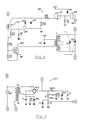
- Figure 2 is a schematic of the oscillator network circuit of the present invention;
- Figure 3 is a block diagram of a feedback network circuit according to the present invention;
- Figures 4a-4e are graphs of the signals of various points in the circuit of Fig. 3; and
- Figures 5-7 are circuit diagrams of certain elements of Fig. 3.
- Referring to Fig. 1, which shows a plasma torch10 according to the present invention, a
tubular torch member 12 is formed of quartz or other electrically insulating material. Ahelical induction coil 14 having about three and one half turns is shaped from copper tubing and encircles the upper part of the torch member generally concentrically therewith. A small diameter pipe16 of similar material or preferably alumina is positioned along the axis of the torch, terminating in the vicinity ofcoil 14 as will be described in detail below. A tubular intermediate member18, preferably of the same composition as the torch member, is located concentrically betweentorch member 12 and pipe16, forming an innerannular space 20 outside pipe16 and a second relatively thin outerannular space 22 insidetorch member 12. Intermediate member18 terminates at about the rearward edge ofcoil 14. - (As used herein and in the claims, " forward" and terms derived therefrom or synonymous or analogous thereto, have reference to the end toward which the plasma flame issues from the gun; similarly "rearward" etc. denote the opposite location.)
Torch member 12, intermediate member18 and pipe16 are affixed concentrically with respect to each other in a mountingmember 24 with O-rings 26.- A
first conduit 38 for conveying plasma-forming gas from asource 40 into innerannular space 20, by way of the piping ofcoil 14 is connected to the lower part of intermediate member18 and extends laterally therefrom. The plasma-forming gas thus flows in a forward direction with respect to torch10; i.e., upwardly in the orientation shown in the present example. Asecond conduit 42 for cooling gas from asource 44 is similarly connected to torchmember 12. Thesources - Flowing the plasma-forming gas through the tubing of
coil 14 was found to have the benefits of cooling the coil and preheating the gas. Surprisingly, sufficient cooling was obtained even at and above 1 KW applied RF power. Preheating the gas results in less of a thermal gradient through the system with improved stability resulting. - The bottom end of the central pipe16 protrudes downwardly through mounting
member 24 and is attached through athird conduit 46 to a source ofcarrier gas 48. A sample of substance from asample container 50 to be introduced into the plasma is fed into the carrier gas flow through avalve 52 from a source of the sample or material, in liquid or powder form. Such substance may be for spectrographic analysis or other treatment by the plasma as desired. Alternatively the carrier gas itself may be the sample. The fluidized sample is thus conveyed upwardly (forwardly) through an orifice54 in pipe16 and injected into a plasma region 55 generated withininduction coil 14 andtorch member 12. - Mounting
member 24 is slidingly retained in atorch body 56 such that the mounting member and itsassembly 58 oftorch member 12, intermediate member18 and pipe16 can be moved vertically. An upper shoulder60 and a lower shoulder62 are provided intorch body 56 to engage respective upper and lower end surfaces64,66 of mountingmember 24 to position the mounting member in an upper (forward) position or lower (rearward) position respectively; the lower position of mountingmember 24 is shown in Fig. 1. Avertical slot 57 intorch body 56 accommodates movement of thegas conduits - A
vertical strut 68 is attached to aside 70 of mountingmember 24 and extends down beyondtorch body 56. A set ofteeth 72 arranged vertically is cut into thestrut 68 to form a rack. Apinion gear 74 engagingteeth 72 is mounted on a shaft76 to which acontrol knob 78 also is mounted. Thus turning of the control knob, by hand, motor, pulley belt or the like (not shown), causesstrut 68, mountingmember 24 andtube assembly 58 to move vertically between the shoulder limits60,62. Mountingmember 24 may be moved by any other desired means, such as a stepper motor. - More reliable ignition of a stable, properly-formed plasma discharge is obtained by vertical position adjustability of the quartz torch. Proper aerodynamic flow at the load coil location is assured so that destructive ring discharges are unable to form during ignition. The adjustment then locates the injector tip at, or close to, the lower location where the plasma forms, which greatly simplifies formation of a sample channel axially through the plasma, and when the sample is subsequently injected it is restricted from circumventing the plasma region.
Induction coil 14 is retained on a tubular mount80 formed of a cylindrical section82 on which the coil is positioned snugly. Tubular mount80 has an axial length that is enough greater than that ofcoil 14 so as to extend the mount to acontact surface 86 ontorch body 56 to positioncoil 14 with respect tobody 56. Preferably the tubular mount also has an upper flange90 extending radially outwardly from cylindrical section82 at the top (forward end) thereof. The upper flange has an outer diameter greater than the outer diameter ofcoil 14 and is adjacent to theforward edge 92 of the coil, so as to provide a radio frequency barrier between the coil and the open end of the torch.Coil 14 is positioned vertically between upper flange90 and alower flange 91.- Continuing with Fig. 1, an electrically
conductive probe 94 is extended through aslot 96 in the forward end of thetorch member 12. The probe is electrically connected to the high voltage output of apiezoelectric crystal 98 capable of yielding a pulse of at least 10 kilovolts, for example about 20 kilovolts. - A
pneumatic piston assembly 100 is supplied by asource 102 of compressed gas through avalve 104 and is connected mechanically to the crystal by arod 106. When the valve is opened a mechanical pulse from the rod to the crystal results in a very high voltage pulse that triggers a spark from thetip 108 ofprobe 94 at the torch. The plasma is initiated by first applying the radio frequency power to the induction coil and then pulsing the crystal. Pulsing may be repeated as necessary at a higher repetition time than the full recovery cycle time of the piezoelectric crystal, allowing creation of sufficient ionized gas intermittently to cause ignition as if a continuously ionized stream was being produced. Starting the plasma discharge in this manner has been found to be highly reliable and the piezoelectric crystal system has a relatively low cost compared to prior reliable starters. - The plasma discharge is thus formed in the torch member in plasma region generally within the induction coil. According to the present invention the injector pipe, and preferably the entire torch assembly is adjusted axially with respect to the induction coil while the plasma discharge is energized. In particular, it was found advantageous to start the plasma while the orifice of the injector pipe is positioned proximate a
hypothetical plane 112 that is oriented perpendicularly to the axis114 of the induction coil in contact with the forward edge of the coil. Such position of the pipe is shown by broken lines114 in Fig. 1. After the plasma is started the injector tip is withdrawn to a second position, which is that shown in the figure, proximate a second plane116 that is oriented perpendicularly to the axis of the coil in contact with therearward edge 118 of the coil. - The radio frequency (RF)
system 200, shown in Fig. 2, is a 40 MHZ tuned power oscillator, capacitively coupled to a high Q tuned output network which powers the inductively coupled plasma. The frequency generally should be between about 20 MHZ and 90 MHZ, preferably between 30 MHZ and 50 MHZ, for example 40 MHZ. Anoscillator network 202 comprises a power triode amplifier203 with a filament circuit204, a feedback and grid leak biasing circuit of inductance Lf, capacitance Cf and resistance Rb, and a tuned plate circuit coil Lp and capacitance Cp. The output of oscillator204 is capacitively coupled through Cc to the output network204 comprising capacitance CL; such capacitive coupling Cc is preferable over inductive coupling due to lower impedance and undesirable effects of heating. Outputnetwork load coil 14 is used to inductively couple the RF power to the plasma. - Coil Lp is conventionally formed of metal sheet which also intrinsically provides the capacitance Cp. The coupling capacitor Cc between the oscillator and the output network is also formed of metal sheet proximate Lp/Cc, shown schematically in Fig. 2 as a tap coming off of coil LP. A tunable capacitor Cl is used to tune the circuit and comprises a third metal sheet variable in position. Once this is adjusted upon assembly of the system it need not be changed again. A capacitance Cs is stray capacitance formed by the proximity of the output network to its enclosure, and is the RF return for
load coil 14. - According to the present invention,
output LC network 206 is tuned without sample injection to a higher frequency thanoscillator network 202, thereby allowing only a predetermined fraction of the oscillator power to be coupled through Cc to the output network and hence to the plasma. During plasma generation the frequency difference between the frequencies ofoscillator network 202 and output network should be between 0.1 MHZ and 2 MHZ. - Typically the frequency difference drops from about 1 MHZ for plasma without sample injection to about 0.4 MHZ as a sample is injected into the plasma. The frequency of
network 206 may even approach the same value as foroscillator 202 with certain sample introductions but may not be a lesser frequency due to instability. When a sample is atomized and injected into the plasma, the flow pattern and composition is changed, causing unfavorable conditions for sustaining the plasma, and the reactive coupling coefficient of thecoil 14 is thereby altered to increase its apparent inductance. This decreases the resonant frequency of the output network to a value that is closer to the frequency of the oscillator, thereby coupling more power to the output network and hence stabilizing the plasma. - The level of power dissipated by the plasma is a function of the coupling coefficient of the load coil to the plasma which is sample dependent, while the power delivered to the plasma for a given sample condition is tightly regulated by the high voltage plate regulation of power triode203. The plate voltage of power triode203 will determine the RF output power delivered to the plasma.
- Preferably the operating power is held constant throughout the changes in coupling between the coil and the plasma. According to a preferred embodiment of the present invention, this is accomplished by means of a feedback network involving sampling the DC plate voltage and varying the fractional size of each of the applied half cycles of AC power supplied to the high voltage transformer primary. This phase control (duty cycle) regulation allows the plate voltage to be adjustable from a few hundred volts to 4.5 KV DC and to be held constant over large line voltage transitions. With the plate voltage set to 3 KV and 75% of max loading, the regulation for the system described hereinbelow was found to be better than 1% when the line voltage was varied from 190 VAC to 256 VAC.
- The operation of the phase control regulator can be seen with the aid of block diagram Fig. 3 and the wave forms shown in Fig. 4. An accurately controlled DC voltage is provided by a
control voltage source 208 and fed throughline 252 to a summingcircuit 210. A feedback signal proportional to the plate voltage of triode203 enterscircuit 210 where it is summed with the control voltage to generate an error voltage. The error voltage is applied throughline 254, acontrol limit network 212 andline 256 to a voltage controlcurrent source 214 which provides a constant source of current proportional to the error voltage. The current fromline 258 charges atiming capacitor 216, which charges linearly as shown in Fig. 4b, because of the constant current supply, at a rate that is determined by the magnitude of the current and, therefore, by the error voltage. The voltage ontiming capacitor 216 is sensed on line260 by avoltage comparator 218. - A synchronizing
reference 224 is driven by the start of each half cycle ofline voltage source 226 obtained throughline 262, a non-filteringfull wave rectifier 228 andline 264.Reference 224 generates zero-crossing pulses synchronized by the line voltage. These pulses, indicated in Fig. 4a, are fed throughline 266 topulse trap 222, which is reset by each pulse. - When the input voltage to
voltage comparator 218 reaches a predetermined voltage, the comparator dischargestiming capacitor 216 into apulse driver 220, vialine 268, which provides a trigger pulse (Fig. 4d) on its output line272. The discharge ofcomparator 218 also fires, via line270, apulse trap 222 which has been reset earlier in the cycle by the zero crossing pulses fromline 266. The output ofpulse trap 222 online 268 is in the form of a square pulse (Fig. 4b) having a duration extending from the zero crossing (reset) to a time in the cycle established by thedischarge timer 216 throughvoltage comparator 218. The initial firing ofpulse trap 222 unleashesvoltage comparator 218 to allowtiming capacitor 216 to start its charging cycle (Fig. 4c). By allowingtiming capacitor 216 to always start its timing cycle referenced to the zero-crossing synchronized pulse, the regulator will always be in synchronization with the line. - The
pulse driver 220 drives a 1:1:1 pulse transformer T1 which determines the firing angle of each of a parallel pair of silicon control rectifiers SCR1, SCR2. These control rectifiers SCR1, SCR2 are in series with the AC power source to the DC power supply, as will be described below. Thus the firing angle and, therefore, the duty cycle (Fig. 4e) of these control rectifiers determine the AC voltage input to the high voltage DC power supply and, therefore, the DC voltage applied to oscillator circuit202 (Fig. 2). As the duty cycle is established inversely to the plate voltage of triode203, any potential change initiated, for example, by a change in the plasma torch load or in the AC power supply, is caused to be nullified by inverse change in the duty cycling provided by the control rectifiers. - As examples, certain circuit details and preferred embodiments of the phase control regulator are provided in Figs. 5-6. With reference to Fig. 5, a feedback signal proportional to the plate voltage of triode203 enters summing
circuit 210 at connection I and is summed with a control voltage of -9.0 volts by operational amplifier U1 to generate an error voltage. The response speed of the phase control regulator is determined by this amplifier; desirably its gain is 34 db with a breakpoint of 2 Hz with the gain decreasing 20 db/decade and reaching 0 db at 50 Hz. - The error voltage from U1 is supplied through
control limit network 212 comprising resistors R13, R14 and zener diode CR15 to voltage controlledcurrent source 214 comprising transistor Q3. - A
timing capacitor 216 is charged linearly by Q3 output because of the constant current supply. - The voltage on
timing capacitor 216 is sensed via connection J byvoltage comparator 218 comprising Q4, Fig. 6, which is a programable unijunction transistor. When the anode voltage of Q4 charges to 0.2V less than the gate voltage, Q4 fires and discharges capacitor216 (from connection J) through resistor R31 into the base ofpulse driver 220 comprising transistor Q5. The pulse generated by Q4 also firespulse trap 222 comprising control rectifier CR8 which, through resistor R17, clamps the gate of Q4 to 0.7V and prevents it from refiring and also preventstimer 216 from recharging. - Pulses to timing capacitor Q4 are synchronized with a synchronizing reference224 (Fig. 6) comprising a buffer field effect transistor Q6 and zener diode CR11. A
line voltage 226 is rectified by afull wave rectifier 228 and fed to the gate of Q6 which, in conjunction with diode CR11, produces zero-crossing pulses (Fig. 4a) of one each half cycle. That buffered signal is limited to 3.9 volts through diode CR11 producing a very clipped pulse with spikes going to ground during zero crossing transients. The zero-crossing sync pulse resets pulse trap CR8 and unlatches Q4 which allowscapacitor 216 to start its charging cycle. - The upper and lower control limit circuit212 (Fig. 5) which comprises resistors R13, R14, and diode CR15 is used to insure that when the regulator is set to the minimum DC output voltage SCR1 and SCR2 fire every half cycle to prevent an imbalance in the transformer; or, when set to maximum DC voltage, that the SCR's are not turned off prematurely due to the small voltage to current phase shift caused by the inductance of the transformer. The maximum inductive phase shift is 14.4° and the minimum delay limit is 27°, the maximum delay limit is 162°. Resistor R8 to U1 in
circuit 210 is used to keep the error voltage high, and Q3 at minimum charging current, to initialize a starting point when both the high voltage and the control voltage are off. - The pulse driver, Q5, drives pulse transformer T1 which triggers silicon control rectifiers SCR1, SCR2. These are rated at 35 amperes continuous at 800V peak.
- A high
DC voltage supply 230, shown in Fig. 7, takes 4,000 volts AC off of the secondary winding high voltage transformer T2 to a full wave rectifier bridge PF6. The network includes a large external capacitor CR of 6 microfarads. Metering resistors R1, R2, R3 include a voltage divider for suitable level of feedback voltage. The plate voltage of tube203 (Fig. 2) is supplied via connection H through choke T3. The feedback voltage of about 0.4 volts is taken between resistor R1 and diode D1 and fed through connection I to the summing circuit210 (Fig. 5). - As indicated hereinabove, the maintenance of a constant power level to the plasma for the duration of each run with a specific test sample is especially desirable while the sample substance is being injection into the plasma. However, the power level may be different for different samples.
- While the invention has been described above in detail with reference to specific embodiments, various changes and modifications which fall within the spirit of the invention and scope of the appended claims will become apparent to those skilled in this art. The invention is therefore only intended to be limited by the appended claims or their equivalents.
Claims (14)
an AC circuit receptive of line voltage for effecting the AC power input including means for duty cycling the AC power in response to a control signal, feedback means for generating a feedback signal relative to the DC voltage output, and control means receptive of the feedback signal for producing the control signal such that a change in the DC voltage output effects an inverse change in the duty cycling whereby the change in the DC voltage output is nullified.
an AC circuit receptive of line voltage for effecting the AC power input including means for duty cycling the AC power in response to a control signal, feedback means for generating a feedback signal relative to the DC voltage output, and control means receptive of the feedback signal for producing the control signal such that a change in the DC voltage output effects an inverse change in the duty cycling whereby the change in the DC voltage output is nullified.
a radio frequency generator including the output LC network and a power triode with a plate and being coupled to the output LC network, a DC power supply for effecting a rectified voltage to the triode plate including an input transformer with a primary winding receptive of AC power, an AC circuit receptive of line voltage for effecting the AC power including means for duty cycling the AC power in response to a control signal, feedback means for generating a feedback signal relative to the rectified voltage, and control means receptive of the feedback signal for producing the control signal such that a change in the rectified voltage effects an inverse change in the duty cycling such as to nullify the change in the rectified voltage.
Applications Claiming Priority (2)
| Application Number | Priority Date | Filing Date | Title |
|---|---|---|---|
| US22838 | 1987-03-06 | ||
| US07/022,838US4818916A (en) | 1987-03-06 | 1987-03-06 | Power system for inductively coupled plasma torch |
Publications (3)
| Publication Number | Publication Date |
|---|---|
| EP0281157A2true EP0281157A2 (en) | 1988-09-07 |
| EP0281157A3 EP0281157A3 (en) | 1990-03-28 |
| EP0281157B1 EP0281157B1 (en) | 1994-06-29 |
Family
ID=21811693
Family Applications (1)
| Application Number | Title | Priority Date | Filing Date |
|---|---|---|---|
| EP88103403AExpired - LifetimeEP0281157B1 (en) | 1987-03-06 | 1988-03-04 | Power system for inductively coupled plasma torch |
Country Status (4)
| Country | Link |
|---|---|
| US (1) | US4818916A (en) |
| EP (1) | EP0281157B1 (en) |
| JP (1) | JP2708447B2 (en) |
| DE (1) | DE3850422T2 (en) |
Cited By (9)
| Publication number | Priority date | Publication date | Assignee | Title |
|---|---|---|---|---|
| DE4037698A1 (en)* | 1990-02-26 | 1991-08-29 | Leco Corp | MULTI-FREQUENCY ACTIVATION CONTROL CIRCUIT FOR AN INDUCTIVELY COUPLED PLASMA GENERATOR |
| EP0465422A3 (en)* | 1990-07-03 | 1992-06-03 | Plasma Technik Ag | Surface coating device |
| EP0602764A1 (en)* | 1992-12-17 | 1994-06-22 | FISONS plc | Inductively coupled plasma spectrometers and radio - frequency power supply therefor |
| US5383019A (en)* | 1990-03-23 | 1995-01-17 | Fisons Plc | Inductively coupled plasma spectrometers and radio-frequency power supply therefor |
| ES2115542A1 (en)* | 1996-07-24 | 1998-06-16 | Iberdrola Sa | Power supply for plasma furnace torches. |
| EP0910231A3 (en)* | 1997-10-15 | 2003-07-16 | The Perkin-Elmer Corporation | Mounting apparatus for induction coupled plasma torch |
| US6740842B2 (en) | 1999-07-13 | 2004-05-25 | Tokyo Electron Limited | Radio frequency power source for generating an inductively coupled plasma |
| DE10345890A1 (en)* | 2003-09-30 | 2005-04-28 | Siemens Ag | Method for stabilizing gas mixture combustion, e.g. for at least one premixture flame in combustion chamber of gas turbine, using plasma to interact with flame in premixture pilot burner, for energy generation without diffusion burner |
| GB2508824A (en)* | 2012-12-11 | 2014-06-18 | Linde Ag | Piezoelectric apparatus for generating voltage from a compressed gas |
Families Citing this family (45)
| Publication number | Priority date | Publication date | Assignee | Title |
|---|---|---|---|---|
| JPH02215038A (en)* | 1989-02-15 | 1990-08-28 | Hitachi Ltd | Microwave plasma trace element analyzer |
| US5055743A (en)* | 1989-05-02 | 1991-10-08 | Spectra Physics, Inc. | Induction heated cathode |
| US5047692A (en)* | 1990-01-30 | 1991-09-10 | General Electric Company | Integrated tuning capacitor network and heat sink for an electrodeless high intensity discharge lamp ballast |
| KR930004713B1 (en)* | 1990-06-18 | 1993-06-03 | 삼성전자 주식회사 | Plasma Generator and Method Using Modulation |
| US5095189A (en)* | 1990-09-26 | 1992-03-10 | General Electric Company | Method for reducing plasma constriction by intermediate injection of hydrogen in RF plasma gun |
| US5159173A (en)* | 1990-09-26 | 1992-10-27 | General Electric Company | Apparatus for reducing plasma constriction by intermediate injection of hydrogen in RF plasma gun |
| NO174180C (en)* | 1991-12-12 | 1994-03-23 | Kvaerner Eng | Burner insertion tubes for chemical processes |
| US5216330A (en)* | 1992-01-14 | 1993-06-01 | Honeywell Inc. | Ion beam gun |
| EP0792091B1 (en)* | 1995-12-27 | 2002-03-13 | Nippon Telegraph And Telephone Corporation | Elemental analysis method |
| US6329757B1 (en) | 1996-12-31 | 2001-12-11 | The Perkin-Elmer Corporation | High frequency transistor oscillator system |
| US6222186B1 (en) | 1998-06-25 | 2001-04-24 | Agilent Technologies, Inc. | Power-modulated inductively coupled plasma spectrometry |
| US7511246B2 (en)* | 2002-12-12 | 2009-03-31 | Perkinelmer Las Inc. | Induction device for generating a plasma |
| US7106438B2 (en)* | 2002-12-12 | 2006-09-12 | Perkinelmer Las, Inc. | ICP-OES and ICP-MS induction current |
| US8057468B2 (en) | 2002-12-17 | 2011-11-15 | Bovie Medical Corporation | Method to generate a plasma stream for performing electrosurgery |
| US7663319B2 (en)* | 2004-02-22 | 2010-02-16 | Zond, Inc. | Methods and apparatus for generating strongly-ionized plasmas with ionizational instabilities |
| AU2012202363B2 (en)* | 2005-03-11 | 2014-08-14 | Perkinelmer U.S. Llc | Plasmas and methods of using them |
| US8633416B2 (en)* | 2005-03-11 | 2014-01-21 | Perkinelmer Health Sciences, Inc. | Plasmas and methods of using them |
| US8622735B2 (en)* | 2005-06-17 | 2014-01-07 | Perkinelmer Health Sciences, Inc. | Boost devices and methods of using them |
| US7742167B2 (en)* | 2005-06-17 | 2010-06-22 | Perkinelmer Health Sciences, Inc. | Optical emission device with boost device |
| US7459899B2 (en) | 2005-11-21 | 2008-12-02 | Thermo Fisher Scientific Inc. | Inductively-coupled RF power source |
| US7863785B2 (en)* | 2007-08-08 | 2011-01-04 | Anadish Kumar Pal | High power-density static-field ac conduction motor |
| US8994270B2 (en) | 2008-05-30 | 2015-03-31 | Colorado State University Research Foundation | System and methods for plasma application |
| WO2009146439A1 (en) | 2008-05-30 | 2009-12-03 | Colorado State University Research Foundation | System, method and apparatus for generating plasma |
| US9288886B2 (en) | 2008-05-30 | 2016-03-15 | Colorado State University Research Foundation | Plasma-based chemical source device and method of use thereof |
| US9649143B2 (en)* | 2009-09-23 | 2017-05-16 | Bovie Medical Corporation | Electrosurgical system to generate a pulsed plasma stream and method thereof |
| US8222822B2 (en) | 2009-10-27 | 2012-07-17 | Tyco Healthcare Group Lp | Inductively-coupled plasma device |
| US8795265B2 (en) | 2010-01-28 | 2014-08-05 | Bovie Medical Corporation | Electrosurgical apparatus to generate a dual plasma stream and method thereof |
| CA2794895A1 (en) | 2010-03-31 | 2011-10-06 | Colorado State University Research Foundation | Liquid-gas interface plasma device |
| EP2552340A4 (en) | 2010-03-31 | 2015-10-14 | Univ Colorado State Res Found | PLASMA DEVICE WITH LIQUID-GAS INTERFACE |
| CN203556992U (en)* | 2010-05-05 | 2014-04-23 | 珀金埃尔默健康科学股份有限公司 | Induction device, torch assembly, optical transmitting device, atomic absorption device, and mass spectrometer |
| US9387269B2 (en) | 2011-01-28 | 2016-07-12 | Bovie Medical Corporation | Cold plasma jet hand sanitizer |
| US20160121418A1 (en)* | 2012-01-25 | 2016-05-05 | Gordon Hanka | Welder Powered Arc Starter |
| EP2904881B1 (en) | 2012-07-13 | 2020-11-11 | PerkinElmer Health Sciences, Inc. | Torches with refractory and not-refractory materials coupled together |
| US9532826B2 (en) | 2013-03-06 | 2017-01-03 | Covidien Lp | System and method for sinus surgery |
| US9555145B2 (en) | 2013-03-13 | 2017-01-31 | Covidien Lp | System and method for biofilm remediation |
| US9504137B2 (en)* | 2013-04-08 | 2016-11-22 | Perkinelmer Health Sciences, Inc. | Capacitively coupled devices and oscillators |
| US9635750B2 (en) | 2013-10-23 | 2017-04-25 | Perkinelmer Health Sciences, Inc. | Oscillator generators and methods of using them |
| EP3061326B1 (en)* | 2013-10-23 | 2021-08-11 | PerkinElmer Health Sciences, Inc. | Hybrid generators and methods of using them |
| WO2017096112A1 (en) | 2015-12-02 | 2017-06-08 | Bovie Medical Corporation | Mixing cold plasma beam jets with atmosphere |
| EP3449700B1 (en)* | 2016-04-27 | 2025-03-12 | PerkinElmer Health Sciences, Inc. | Oscillator generators and methods of using them |
| US10918433B2 (en) | 2016-09-27 | 2021-02-16 | Apyx Medical Corporation | Devices, systems and methods for enhancing physiological effectiveness of medical cold plasma discharges |
| NL2018778B1 (en) | 2017-04-25 | 2018-11-05 | Skil B V | Power tool |
| CN107634587B (en)* | 2017-09-20 | 2024-06-11 | 扬州芯智瑞电子科技有限公司 | Improved wireless power supply system based on Tesla coil |
| US10798809B2 (en)* | 2018-07-13 | 2020-10-06 | Shimadzu Coporation | Inductively coupled plasma generator |
| CN216928483U (en)* | 2021-12-01 | 2022-07-08 | 费勉仪器科技(南京)有限公司 | Embedded radio frequency plasma source generating device and vacuum processing system |
Family Cites Families (4)
| Publication number | Priority date | Publication date | Assignee | Title |
|---|---|---|---|---|
| US3467471A (en)* | 1963-10-21 | 1969-09-16 | Albright & Wilson Mfg Ltd | Plasma light source for spectroscopic investigation |
| US3958883A (en)* | 1974-07-10 | 1976-05-25 | Baird-Atomic, Inc. | Radio frequency induced plasma excitation of optical emission spectroscopic samples |
| US4225769A (en)* | 1977-09-26 | 1980-09-30 | Thermal Dynamics Corporation | Plasma torch starting circuit |
| ZA841218B (en)* | 1983-03-08 | 1984-09-26 | Allied Corp | Plasma excitation system |
- 1987
- 1987-03-06USUS07/022,838patent/US4818916A/ennot_activeExpired - Lifetime
- 1988
- 1988-03-04DEDE3850422Tpatent/DE3850422T2/ennot_activeExpired - Fee Related
- 1988-03-04EPEP88103403Apatent/EP0281157B1/ennot_activeExpired - Lifetime
- 1988-03-07JPJP63051794Apatent/JP2708447B2/ennot_activeExpired - Lifetime
Cited By (9)
| Publication number | Priority date | Publication date | Assignee | Title |
|---|---|---|---|---|
| DE4037698A1 (en)* | 1990-02-26 | 1991-08-29 | Leco Corp | MULTI-FREQUENCY ACTIVATION CONTROL CIRCUIT FOR AN INDUCTIVELY COUPLED PLASMA GENERATOR |
| US5383019A (en)* | 1990-03-23 | 1995-01-17 | Fisons Plc | Inductively coupled plasma spectrometers and radio-frequency power supply therefor |
| EP0465422A3 (en)* | 1990-07-03 | 1992-06-03 | Plasma Technik Ag | Surface coating device |
| EP0602764A1 (en)* | 1992-12-17 | 1994-06-22 | FISONS plc | Inductively coupled plasma spectrometers and radio - frequency power supply therefor |
| ES2115542A1 (en)* | 1996-07-24 | 1998-06-16 | Iberdrola Sa | Power supply for plasma furnace torches. |
| EP0910231A3 (en)* | 1997-10-15 | 2003-07-16 | The Perkin-Elmer Corporation | Mounting apparatus for induction coupled plasma torch |
| US6740842B2 (en) | 1999-07-13 | 2004-05-25 | Tokyo Electron Limited | Radio frequency power source for generating an inductively coupled plasma |
| DE10345890A1 (en)* | 2003-09-30 | 2005-04-28 | Siemens Ag | Method for stabilizing gas mixture combustion, e.g. for at least one premixture flame in combustion chamber of gas turbine, using plasma to interact with flame in premixture pilot burner, for energy generation without diffusion burner |
| GB2508824A (en)* | 2012-12-11 | 2014-06-18 | Linde Ag | Piezoelectric apparatus for generating voltage from a compressed gas |
Also Published As
| Publication number | Publication date |
|---|---|
| EP0281157A3 (en) | 1990-03-28 |
| DE3850422D1 (en) | 1994-08-04 |
| EP0281157B1 (en) | 1994-06-29 |
| JPS63304598A (en) | 1988-12-12 |
| US4818916A (en) | 1989-04-04 |
| JP2708447B2 (en) | 1998-02-04 |
| DE3850422T2 (en) | 1994-11-10 |
Similar Documents
| Publication | Publication Date | Title |
|---|---|---|
| US4818916A (en) | Power system for inductively coupled plasma torch | |
| EP0281158B1 (en) | Inductively coupled plasma torch | |
| JPH01699A (en) | Inductive plasma generator and method | |
| US10064263B2 (en) | Cold plasma treatment devices and associated methods | |
| US3347698A (en) | Radio frequency plasma flame spraying | |
| US4557819A (en) | System for igniting and controlling a wafer processing plasma | |
| CA1271229A (en) | Plasma flame spray gun method and apparatus with adjustable ratio of radial and tangential plasma gas flow | |
| US5383019A (en) | Inductively coupled plasma spectrometers and radio-frequency power supply therefor | |
| US4482246A (en) | Inductively coupled plasma discharge in flowing non-argon gas at atmospheric pressure for spectrochemical analysis | |
| CA2034459C (en) | Low frequency radio frequency plasma spray deposition | |
| EP0602764A1 (en) | Inductively coupled plasma spectrometers and radio - frequency power supply therefor | |
| US5587630A (en) | Continuous plasma ignition system | |
| US4306175A (en) | Induction plasma system | |
| US4142089A (en) | Pulsed coaxial thermal plasma sprayer | |
| US8080944B2 (en) | Ignition device | |
| EP0940063B1 (en) | Lamp driver circuit and method | |
| US5159173A (en) | Apparatus for reducing plasma constriction by intermediate injection of hydrogen in RF plasma gun | |
| JP5305900B2 (en) | Apparatus and method for applying plasma coating | |
| US4146819A (en) | Method for varying voltage in a high intensity discharge mercury lamp | |
| JP2908912B2 (en) | Plasma ignition method in induction plasma generator | |
| NZ229175A (en) | High frequency induction heating of thin filaments | |
| US3488426A (en) | Apparatus for uniform vaporisation of high melting materials in particular quartz | |
| JP3042119B2 (en) | Plasma ignition power supply | |
| JP5597340B2 (en) | Plasma processing of large volume components | |
| JPH09223595A (en) | High frequency inductively coupled arc plasma ignition method and plasma generator |
Legal Events
| Date | Code | Title | Description |
|---|---|---|---|
| PUAI | Public reference made under article 153(3) epc to a published international application that has entered the european phase | Free format text:ORIGINAL CODE: 0009012 | |
| AK | Designated contracting states | Kind code of ref document:A2 Designated state(s):DE FR GB | |
| PUAL | Search report despatched | Free format text:ORIGINAL CODE: 0009013 | |
| AK | Designated contracting states | Kind code of ref document:A3 Designated state(s):DE FR GB | |
| 17P | Request for examination filed | Effective date:19900928 | |
| 17Q | First examination report despatched | Effective date:19930210 | |
| GRAA | (expected) grant | Free format text:ORIGINAL CODE: 0009210 | |
| AK | Designated contracting states | Kind code of ref document:B1 Designated state(s):DE FR GB | |
| REF | Corresponds to: | Ref document number:3850422 Country of ref document:DE Date of ref document:19940804 | |
| ET | Fr: translation filed | ||
| PLBE | No opposition filed within time limit | Free format text:ORIGINAL CODE: 0009261 | |
| STAA | Information on the status of an ep patent application or granted ep patent | Free format text:STATUS: NO OPPOSITION FILED WITHIN TIME LIMIT | |
| 26N | No opposition filed | ||
| REG | Reference to a national code | Ref country code:GB Ref legal event code:IF02 | |
| PGFP | Annual fee paid to national office [announced via postgrant information from national office to epo] | Ref country code:DE Payment date:20020228 Year of fee payment:15 | |
| PGFP | Annual fee paid to national office [announced via postgrant information from national office to epo] | Ref country code:FR Payment date:20020305 Year of fee payment:15 | |
| PGFP | Annual fee paid to national office [announced via postgrant information from national office to epo] | Ref country code:GB Payment date:20020307 Year of fee payment:15 | |
| PG25 | Lapsed in a contracting state [announced via postgrant information from national office to epo] | Ref country code:GB Free format text:LAPSE BECAUSE OF NON-PAYMENT OF DUE FEES Effective date:20030304 | |
| PG25 | Lapsed in a contracting state [announced via postgrant information from national office to epo] | Ref country code:DE Free format text:LAPSE BECAUSE OF NON-PAYMENT OF DUE FEES Effective date:20031001 | |
| GBPC | Gb: european patent ceased through non-payment of renewal fee | ||
| PG25 | Lapsed in a contracting state [announced via postgrant information from national office to epo] | Ref country code:FR Free format text:LAPSE BECAUSE OF NON-PAYMENT OF DUE FEES Effective date:20031127 | |
| REG | Reference to a national code | Ref country code:FR Ref legal event code:ST |