EP0274950B1 - Broad-band coupling device between the delay line of a travelling-wave tube and the external energy-transmitting circuit, and travelling-wave tube comprising such a device - Google Patents
Broad-band coupling device between the delay line of a travelling-wave tube and the external energy-transmitting circuit, and travelling-wave tube comprising such a deviceDownload PDFInfo
- Publication number
- EP0274950B1 EP0274950B1EP87402855AEP87402855AEP0274950B1EP 0274950 B1EP0274950 B1EP 0274950B1EP 87402855 AEP87402855 AEP 87402855AEP 87402855 AEP87402855 AEP 87402855AEP 0274950 B1EP0274950 B1EP 0274950B1
- Authority
- EP
- European Patent Office
- Prior art keywords
- guide
- wave tube
- molding
- travelling
- delay line
- Prior art date
- Legal status (The legal status is an assumption and is not a legal conclusion. Google has not performed a legal analysis and makes no representation as to the accuracy of the status listed.)
- Expired - Lifetime
Links
- 230000008878couplingEffects0.000titleclaimsdescription18
- 238000010168coupling processMethods0.000titleclaimsdescription18
- 238000005859coupling reactionMethods0.000titleclaimsdescription18
- 230000007423decreaseEffects0.000claimsdescription2
- 238000000465mouldingMethods0.000description50
- 238000001816coolingMethods0.000description3
- 230000007704transitionEffects0.000description3
- 230000000694effectsEffects0.000description2
- 230000006978adaptationEffects0.000description1
- 238000010276constructionMethods0.000description1
- 238000010894electron beam technologyMethods0.000description1
- 230000001373regressive effectEffects0.000description1
Images


Classifications
- H—ELECTRICITY
- H01—ELECTRIC ELEMENTS
- H01J—ELECTRIC DISCHARGE TUBES OR DISCHARGE LAMPS
- H01J23/00—Details of transit-time tubes of the types covered by group H01J25/00
- H01J23/36—Coupling devices having distributed capacitance and inductance, structurally associated with the tube, for introducing or removing wave energy
- H01J23/40—Coupling devices having distributed capacitance and inductance, structurally associated with the tube, for introducing or removing wave energy to or from the interaction circuit
- H01J23/42—Coupling devices having distributed capacitance and inductance, structurally associated with the tube, for introducing or removing wave energy to or from the interaction circuit the interaction circuit being a helix or a helix-derived slow-wave structure
- H—ELECTRICITY
- H01—ELECTRIC ELEMENTS
- H01P—WAVEGUIDES; RESONATORS, LINES, OR OTHER DEVICES OF THE WAVEGUIDE TYPE
- H01P5/00—Coupling devices of the waveguide type
- H01P5/08—Coupling devices of the waveguide type for linking dissimilar lines or devices
Definitions
- the present inventionrelates to a device for coupling between on one side the delay line of a power traveling wave tube, in which the focusing of the electron beam is carried out using annular, permanent, alternating magnets and on the other side an external circuit for transmitting the energy of the tube, constituted by a waveguide with double molding; the invention relates more specifically to a device comprising a small waveguide, generally with simple molding, of reduced dimensions so as not to exceed the thickness, measured parallel to the axis of the tube, of that of the permanent magnets that it crosses to ensure the coupling between the delay line located inside the focuser and the waveguide with double molding located outside the focuser.
- Such a coupling device corresponding to the preamble of claim 1is known from FR-A-2 485 801, where the small waveguide is a straight guide which opens into the output waveguide, with one of the two moldings of the outlet guide which constitutes an extension of the molding of the small guide and the other of the two moldings which is reduced, until disappearing, before reaching the end of the guide with double molding coupled to the small guide.
- Such a coupling devicean exemplary embodiment of which will be described with the aid of FIG. 1 of this text, has an insufficient bandwidth for certain applications; moreover, by its construction, it is quite bulky.
- Document US-A-3,188,583describes a regressive wave tube with an RF output formed by a coaxial line. The impedance of this line preferably corresponds to the impedance of the delay structure of the tube. Between this coaxial line and another waveguide an impedance matching is used.
- the object of the present inventionis to reduce the above-mentioned drawbacks.
- the small guideis bent so as to be able to arrange, for example, the output guide with double molding parallel to the traveling wave tube.
- a device for coupling between the delay line of a traveling wave tube and the external circuit for transmitting the energy of the tube consisting of a first waveguide having first and second moldingthis device comprising a second waveguide coupled in a junction plane to the first guide and having a single molding connected, at one of its ends, to the delay line and, at the other of its ends, to the first molding, is characterized in that the second molding is short-circuited in the junction plane, in that the first guide comprises an impedance transformer, in that the second guide is at substantially constant impedance, and in that the width of the second guide is, at least substantially, equal to that of the first guide in the junction plane and is reduced in the direction of the delay line.
- Figures la to 1care sectional views of a coupling device according to FR-A-2 485 801.
- Figure tashows a delay line, 1, of a traveling wave tube; it is a helical line, of axis XX ′, with its propeller 10 and its centering rods such as 11.
- the delay line 1is disposed inside a focusing device 2 with annular permanent magnets , alternating such as 20, 22 separated by annular polar masses such as 21, 23.
- An external circuit for transmitting the energy of the tubeconstituted by a rectangular guide 4 with two moldings 40 ', 41', is coupled to line delay 1.
- the coupling device between the line 1 and the guide 4comprises a small guide 3 which passes through the magnet 20 without exceeding the width, measured parallel to the axis XX ', of this magnet; the small guide 3 has a molding 30 'which, on one side, is welded to the end of the propeller 10 and, on the other side, extends into the molding 40' of the guide 4.
- the guides 3 and 4are straight guides arranged perpendicular to the axis XX '; their transverse dimensions are constant so that the junction between these two guides takes place by an abrupt transition in the two transverse dimensions of the guides; the molding 41 ′ of the guide 4 decreases until it disappears completely before reaching the end of the guide 4 coupled to the small guide 3.
- Figures 1b and 1are sectional views of the guide 4 and the small guide 3 according to sectional planes, the respective traces AA and BB are shown in Figure 1 a.
- Figures 2a and 2bshow a coupling device according to the invention.
- FIG. 2ais a view in longitudinal section which, like FIG. 1a, shows a delay line, 1, a traveling wave tube; the line is a propeller line arranged inside a focusing 2, with alternating annular magnets, equipped with cooling fins such as 25.
- a small waveguide 3provided with a single molding 30 has a single molding 30 through which the end of the propeller 10 of the line 1 is welded; on the other side, the molding is extended in the molding 40 by a rectangular guide with two moldings 40, 41, which constitutes the external circuit for transmitting the energy of the tube.
- Figure 2bis a sectional view along the section plane, the trace CC of which is shown in Figure 2a. This view shows the connection of the molding 30 to the propeller 10 and its extension in the molding 40.
- the elbowis a right angle elbow located at the junction of guides 3 and 4; its main role is to allow the guide 4 to be arranged parallel to the tube 1 in order to reduce the size of the assembly; incidentally it allows better cooling of the tube 1, some of its cooling fins being brazed on the guide 4 and therefore benefiting from its mass to ensure the flow of calories from the tube 1.
- zone D2before arriving at the bend, the dimensions of the guide 3 and its molding 30 are gradually increased by arranging so that the increase in the dimensions of the guide are compensated by those of the molding for the effects on the characteristic impedance of the guide; thus in zone D2 the small guide 3 has a constant characteristic impedance equal to Z1.
- the length of the area D 2is a function of the standing wave ratio (ROS) admissible in the working frequency band. With a length corresponding to a quarter of the average wavelength in the band 4.75 - 11 GHz, a SWR less than or equal to 1.92 has been measured in this band and, with a length equal to three quarters of this length. medium wave, an ROS less than or equal to 1.29 was measured.
- ROSstanding wave ratio
- zone D3where the bend is located, the dimensions continue to increase while maintaining the same characteristic impedance; for the molding 30 the increase is made until reaching the dimensions of the molding 40, for the long side of the small guide 3 until reaching the size of the long side of the guide 4 and for the short side of the guide 3 until to a dimension which turns out to be less than that of the guide 4 at the junction point; there is therefore a gradual transition for the moldings 30, 40 and the short sides and abrupt transition for the long sides; the molding 41 ends in short circuit, Y, in the plane of the junction of the guides 3 and 4. From this junction plane the two moldings 40, 41 of the guide 4 are present and the guide 4 has small and large sides whose dimensions will not vary.
- the guide 4is a guide with double molding of standard dimensions, marketed under the reference WRD 475 D 24 and having a characteristic impedance equal to Z3 and a cross section of 27.68 mm X 12.85 mm.
- the guide 4is provided, in its part not shown in FIG. 2a, with a sealed window with a wide strip.
- zone D4which makes it possible to lower the characteristic impedance of the guide with double molding 4, before reaching the junction plane with the small guide with single molding 3, is necessary for the conservation of the bandwidth of the standard guide with double molding; this change can not only be made as indicated in FIG. 3a thanks to a transformer with successive stages of the Tchebycheff type but also by an impedance transformer of linear, exponential, cosinosoidal, parabolic type.
- FIGS. 3a to 3dare sectional views of the guides 3 and 4 of another coupling device according to the invention which is distinguished from that according to Figures 2a, 2b only by the fact that the guides 3 and 4 are in the extension of each other, that is to say do not form an elbow.
- FIG. 3ais a longitudinal section while the sections 3b, 3c, 3d are transverse sections, the traces of the respective sectional planes of which have been indicated in FIG. 3a. Everything that has been said about the guides 3 and 4 of FIGS. 2a, 2b applies to the guides 3 and 4 of FIGS. 3a to 3d, with the exception of the elbow, as can be seen from the figures.
- FIG. 3ais particularly interesting because it clearly shows the short-circuiting, Y, of the molding 41 of the guide 4 in the plane of junction with the small guide 3.
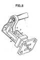
- FIGS 4, 5 and 6are partial perspective views showing different variants of coupling devices according to the invention; in these figures where the focalizers are not represented, tear-offs make it possible to see how the moldings of the guides are produced.
- Figure 4is a view which corresponds to the real sation according to Figures 2a, 2b, that is to say an embodiment with curvature in the plane E and with the molding 30 of the small guide 3 which is connected to that, 40, of the two moldings of the guide 4 which is the closer to delay line 1; the short-circuited end, Y, of the other molding, 41, of the guide 4 appears clearly in FIG. 4.
- FIG. 5corresponds to FIG. 4 with the difference that the molding 40, which is connected to the molding 30 of the small guide 3, is that of the two moldings of the guide 4 which is the farthest from the delay line 1.
- FIG. 6is an embodiment with curvature in the plane H, that is to say an embodiment where the guide 4 is found to be arranged orthogonally with respect to the delay line 1.
- this elbowmay not be at the junction plane of these guides but somewhere in the guide 3 or in the guide 4.
Landscapes
- Control Of Motors That Do Not Use Commutators (AREA)
- Microwave Tubes (AREA)
Description
Translated fromFrenchLa présente invention concerne un dispositif de couplage entre d'un côté la ligne à retard d'un tube à ondes progressives de puissance, dans lequel la focalisation du faisceau d'électrons est réalisée à l'aide d'aimants annulaires, permanents, alternés et de l'autre côté un circuit externe de transmission de l'énergie du tube, constitué par un guide d'ondes à double moulure ; l'invention concerne plus spécialement un dispositif comportant un petit guide d'ondes, généralement à simple moulure, de dimensions réduites de manière à ne pas excéder l'épaisseur, mesurée parallèlement à l'axe du tube, de celui des aimants permanents qu'il traverse pour assurer le couplage entre la ligne à retard située à l'intérieur du focalisateur et le guide d'ondes à double moulure situé à l'extérieur du focalisateur.The present invention relates to a device for coupling between on one side the delay line of a power traveling wave tube, in which the focusing of the electron beam is carried out using annular, permanent, alternating magnets and on the other side an external circuit for transmitting the energy of the tube, constituted by a waveguide with double molding; the invention relates more specifically to a device comprising a small waveguide, generally with simple molding, of reduced dimensions so as not to exceed the thickness, measured parallel to the axis of the tube, of that of the permanent magnets that it crosses to ensure the coupling between the delay line located inside the focuser and the waveguide with double molding located outside the focuser.
Un tel dispositif de couplage correspondant au préambule de la revendication 1 est connu par FR-A-2 485 801, où le petit guide d'ondes est un guide droit qui débouche dans le guide d'ondes de sortie, avec l'une des deux moulures du guide de sortie qui constitue un prolongement de la moulure du petit guide et l'autre des deux moulures qui va en se réduisant, jusqu'à disparaître, avant d'avoir atteint l'extrémité du guide à double moulure couplée au petit guide. Un tel dispositif de couplage, dont un exemple de réalisation sera décrit à l'aide de la figure 1 de ce texte, présente une largeur de bande insuffisante pour certaines applications ; de plus, de par sa réalisation, il est assez encombrant. Le document US-A-3.188.583 décrit un tube à ondes régressives avec une sortie-RF formée par une ligne coaxiale. L'impédance de cette ligne correspond de préférence à l'impédance de la structure à retard du tube. Entre cette ligne coaxiale et un autre guide d'ondes on utilise un adaptement d'impédance.Such a coupling device corresponding to the preamble of
La présente invention a pour but de réduire les inconvénients sus-mentionnés.The object of the present invention is to reduce the above-mentioned drawbacks.
Ceci est obtenu en particulier en effectuant un changement d'impédance dans le guide de sortie, en mettant en court-circuit celle des deux moulures du guide de sortie qui ne constitue pas le prolongement de la moulure du petit guide et en réduisant progressivement, du guide à double moulure vers la ligne à retard, les dimensions du petit guide mais en conservant une impédance sensiblement constate. Subsidiairement, dans le but de réduire l'encombrement de l'ensemble, le petit guide est coudé afin de pouvoir disposer, par exemple, le guide de sortie à double moulure parallèlement au tube à onde progressive.This is obtained in particular by making a change of impedance in the output guide, by short-circuiting that of the two moldings of the output guide which does not constitute the extension of the molding of the small guide and by gradually reducing, from guide with double molding towards the delay line, the dimensions of the small guide but retaining a substantially noted impedance. Alternatively, in order to reduce the overall size of the assembly, the small guide is bent so as to be able to arrange, for example, the output guide with double molding parallel to the traveling wave tube.
Selon l'invention, un dispositif de couplage entre la ligne à retard d'un tube à onde progressive et le circuit externe de transmission de l'énergie du tube constitué par un premier guide d'ondes ayant une première et une seconde moulure, ce dispositif comportant un second guide d'ondes couplé dans un plan de jonction au premier guide et ayant une moulure unique reliée, à l'une de ses extrémités, à la ligne de retard et, à l'autre de ses extrémités, à la première moulure, est caractérisé en ce que la seconde moulure est en court-circuit dans le plan de jonction, en ce que le premier guide comporte un transformateur d'impédance, en ce que le second guide est à impédance sensiblement constante, et en ce que la largeur du second guide est, au moins sensiblement, égale à celle du premier guide dans le plan de jonction et se réduit en direction de la ligne à retard.According to the invention, a device for coupling between the delay line of a traveling wave tube and the external circuit for transmitting the energy of the tube consisting of a first waveguide having first and second molding, this device comprising a second waveguide coupled in a junction plane to the first guide and having a single molding connected, at one of its ends, to the delay line and, at the other of its ends, to the first molding, is characterized in that the second molding is short-circuited in the junction plane, in that the first guide comprises an impedance transformer, in that the second guide is at substantially constant impedance, and in that the width of the second guide is, at least substantially, equal to that of the first guide in the junction plane and is reduced in the direction of the delay line.
La présente invention sera mieux comprise et d'autres caractéristiques apparaîtront à l'aide de la description ci-après et des figures s'y rapportant qui représentent :
- - les figures la à 1 des coupes relatives à un dispositif de couplage selon l'art connu,
- - les figures 2a et 2b des coupes relatives à un premier dispositif de couplage selon l'invention,
- - les figures 3a à 3d des coupes relatives à un deuxième dispositif de couplage selon l'invention,
- - les figures 4 à 6 des vues avec arrachés de parties de dispositifs de couplage selon l'invention.
- FIGS. 1a to 1 of the sections relating to a coupling device according to the known art,
- FIGS. 2a and 2b of the sections relating to a first coupling device according to the invention,
- FIGS. 3a to 3d of the sections relating to a second coupling device according to the invention,
- - Figures 4 to 6 views with cutaway parts of coupling devices according to the invention.
Sur les différentes figures les éléments correspondants sont désignés par les mêmes repères.In the various figures, the corresponding elements are designated by the same references.
Les figures la à 1c sont des vues en coupe d'un dispositif de couplage selon FR-A-2 485 801.Figures la to 1c are sectional views of a coupling device according to FR-A-2 485 801.
La figure ta montre une ligne à retard, 1, d'un tube à onde progressive ; il s'agit d'une ligne en hélice, d'axe XX', avec son hélice 10 et ses bâtonnets de centrage tels que 11. La ligne à retard 1 est disposée à l'intérieur d'un focalisateur 2 à aimants permanents annulaire, alternés tels que 20, 22 séparés par des masses polaires annulaires telles que 21, 23. Un circuit externe de transmission de l'énergie du tube, constitué par un guide rectangulaire 4 à deux moulures 40', 41', est couplé à ligne à retard 1. Le dispositif de couplage entre la ligne 1 et le guide 4 comporte un petit guide 3 qui traverse l'aimant 20 sans déborder de la largeur, mesurée parallèlement à l'axe XX', de cet aimant ; le petit guide 3 comporte une moulure 30' qui, d'un côté, est soudée sur l'extrémité de l'hélice 10 et, de l'autre côté, se prolonge dans la moulure 40' du guide 4. Les guides 3 et 4 sont des guides droits disposés perpendiculairement à l'axe XX'; leurs dimensions transversales sont constantes si bien que la jonction entre ces deux guides se fait par une transition brusque dans les deux dimensions transversales des guides ; la moulure 41' du guide 4 va en se réduisant jusqu'à disparaître complètement avant d'avoir atteint l'extrémité du guide 4 couplée au petit guide 3.Figure ta shows a delay line, 1, of a traveling wave tube; it is a helical line, of axis XX ′, with its
Les figures 1b et 1 sont des vues en coupe du guide 4 et du petit guide 3 selon des plans de coupe dont les traces respectives AA et BB sont indiquées sur la figure 1 a.Figures 1b and 1 are sectional views of the
Avec un montage comme celui des figures 1 a à 1 c, même en modifiant les dimensions de la moulure 30' dans sa traversée du focalisateur 2 comme il est suggéré mais non décrit dans le brevet français sus-mentionné, la largeur de bande est insuffisante dans certaines applications; c'est pourquoi d'autres montages ont été conçus dans le but d'améliorer cette largeur de bande.With an assembly like that of FIGS. 1 a to 1 c, even by modifying the dimensions of the
Les figures 2a et 2b montrent un dispositif de couplage selon l'invention.Figures 2a and 2b show a coupling device according to the invention.
La figure 2a est une vue en coupe longitudinale qui, comme la figure 1a, montre une ligne à retard, 1, d'un tube à ondes progressives ; la ligne est une ligne à hélice disposée à l'intérieur d'un focalisateur 2, à aimants annulaires alternés, équipé d'ailettes de refroidissement telles que 25. Comme dans le montage selon la figure 1a, l'un des aimants, 20, du focalisateur est traversé par un petit guide d'ondes 3 muni d'une seule moulure 30 sur laquelle, d'un côté est soudée l'extrémité de l'hélice 10 de la ligne 1; de l'autre côté, la moulure se prolonge dans la moulure 40 d'un guide rectangulaire à deux moulures 40, 41, qui constitue le circuit externe de transmission de l'énergie du tube.FIG. 2a is a view in longitudinal section which, like FIG. 1a, shows a delay line, 1, a traveling wave tube; the line is a propeller line arranged inside a focusing 2, with alternating annular magnets, equipped with cooling fins such as 25. As in the assembly according to FIG. 1a, one of the magnets, 20, a small waveguide 3 provided with a
La figure 2b est une vue en coupe, selon le plan de coupe dont la trace CC est indiquée sur la figure 2a. Cette vue montre le raccordement de la moulure 30 à l'hélice 10 et son prolongement dans la moulure 40.Figure 2b is a sectional view along the section plane, the trace CC of which is shown in Figure 2a. This view shows the connection of the
Le dispositif de couplage du montage selon les figures 2a, 2b diffère principalement de celui selon les figures 1 a, 1 b par :
- - un coude dans le plan E des guides 3 et 4 c'est-à-dire dans un plan parallèle à leurs petits côtés
- - une structure différente des guides 3 et 4 et de leurs moulures.
- - a bend in the plane E of the
guides 3 and 4, that is to say in a plane parallel to their short sides - - a different structure from
guides 3 and 4 and their moldings.
Le coude est un coude à angle droit situé à la jonction des guides 3 et 4 ; il a principalement pour rôle de permettre de disposer le guide 4 parallèlement au tube 1 afin de réduire l'encombrement du montage ; accessoirement il permet un meilleur refroidissement du tube 1, certaines de ses ailettes de refroidissement étant brasés sur le guide 4 et bénéficiant donc de sa masse pour assurer l'écoulement des calories provenant du tube 1.The elbow is a right angle elbow located at the junction of
La différence de structure des guides 3 et 4 et de leurs moulures par rapport au montage selon les figures 1a, 1b peut être étudiée en considérant cinq zones successives D1 à D5, dans les guides 3 et 4, dont la première D1 est celle où le petit guide, 3, traverse l'aimant 20.The difference in structure of
Dans la zone D1 le guide 3 travers l'aimant 20 du focalisateur 2 ; ses dimensions et celles de sa moulure sont constantes et sont choisies de manière que son impédance caractéristique Z1 soit assez proche de celle de l'hélice (Ze=60 ohms) afin d'obtenir une adaptation à très large bande : plus d'une octave.In zone D1 the guide 3 passes through the
Dans la zone D2, avant d'arriver au coude, les dimensions du guide 3 et de sa moulure 30 sont progressivement augmentées en s'arrangeant pour que l'augmentation des dimensions du guide soient compensées par celles de la moulure pour les effets sur l'impédance caractéristique du guide ; ainsi dans la zone D2 le petit guide 3 est à impédance caractéristique constante égale à Z1. La longueur de la zone D2 est fonction du rapport d'onde stationnaire (R.O.S) admissible dans la bande de fréquence de travail. Avec une longueur correspondant au quart de la longueur d'onde moyenne dans la bande 4,75 - 11 GHz il a été mesuré un R.O.S inférieur ou égal à 1,92 dans cette bande et, avec une longueur égale aux trois quarts de cette longuer d'onde moyenne, il a été mesuré un R.O.S. inférieur ou égal à 1,29.In zone D2, before arriving at the bend, the dimensions of the guide 3 and its
Dans la zone D3, là où se trouve le coude, les dimensions continuent d'augmenter tout en conservant la même impédance caractéristique ; pour la moulure 30 l'augmentation se fait jusqu'à atteindre les dimensions de la moulure 40, pour le grand côté du petit guide 3 jusqu'à atteindre la dimension du grand côté du guide 4 et pour le petit côté du guide 3 jusqu'à une dimension qui s'avère inférieure à celle du guide 4 au point de jonction ; il y a donc transis- tion progressive pour les moulures 30, 40 et les petits côtés et transition brusque pour les grands côtés ; la moulure 41 aboutit en court-circuit, Y, dans le plan de la jonction des guides 3 et 4. A partir de ce plan de jonction les deux moulures 40, 41 du guide 4 sont présentes et le guide 4 a des petits et des grands côtés dont les dimensions ne varieront pas. L'impédance caractéristique qui était Z1 = 60 ohms avant le plan de jonction est passée à la valeur Z2 = 62 ohmsIn zone D3, where the bend is located, the dimensions continue to increase while maintaining the same characteristic impedance; for the
Dans la zone D4 l'écartement entre les moulures 40 et 41 du guide 4 est augmenté par paliers successifs afin de réaliser un changement d'impédance progressif en augmentant l'impédance caractéristique du guide 4 jusqu'à la valeur Z3 = 156 ohms dans la zone D5.In zone D4 the spacing between the
Dans la zone D5 et au delà, le guide 4 est un guide à double moulure de dimensions standard, commercialisé sous la référence WRD 475 D 24 et présentant une impédance caractéristique égale à Z3 et une section droite de 27,68 mm X 12,85 mm. De manière classique le guide 4 est muni, dans sa partie non représentée sur la figure 2a, d'une fenêtre étanche à large bande.In zone D5 and beyond, the
Le changement d'impédance, dans la zone D4, qui permet de baisser l'impédance caractéristique du guide à double moulure 4, avant d'atteindre le plan de jonction avec le petit guide à simple moulure 3, est nécessaire à la conservation de la bande passante du guide standard à double moulure ; ce changement peut non seulement se faire comme indiqué sur la figure 3a grâce à un transformateur à paliers successifs du type Tchebycheff mais également par un transformateur d'impédance de type linéaire, exponentiel, cosinosoïdal, parabolique.The change of impedance, in zone D4, which makes it possible to lower the characteristic impedance of the guide with
Les figures 3a à 3d sont des vues en coupe des guides 3 et 4 d'un autre dispositif de couplage selon l'invention qui ne se distingue de celui selon les figures 2a, 2b que par le fait que les guides 3 et 4 sont dans le prolongement l'un de l'autre, c'est-à-dire ne forment pas un coude. La figure 3a est une coupe longitudinale tandis que les coupes 3b, 3c, 3d sont des coupes transversales dont les traces des plans de coupe respectifs ont été indiquées sur la figure 3a. Tout ce qui a été dit au sujet des guides 3 et 4 des figures 2a, 2b s'applique aux guides 3 et 4 des figures 3a à 3d, à l'exception du coude, comme il ressort des figures. La figure 3a est particulièrement intéressante parce qu'elle montre bien la mise en court-circuit, Y, de la moulure 41 du guide 4 dans le plan de jonction avec le petit guide 3.Figures 3a to 3d are sectional views of the
Les figures 4, 5 et 6 sont des vues partielles, en perspective, montrant différentes variantes de dispositifs de couplage selon l'invention ; sur ces figures où ne sont pas représentés les focalisateurs, des arrachés permettent de voir comment sont réalisées les moulures des guides.Figures 4, 5 and 6 are partial perspective views showing different variants of coupling devices according to the invention; in these figures where the focalizers are not represented, tear-offs make it possible to see how the moldings of the guides are produced.
La figure 4 est une vue qui correspond à la réalisation selon les figures 2a, 2b, c'est-à-dire à une réalisation avec courbure dans le plan E et avec la moulure 30 du petit guide 3 qui est reliée à celle, 40, des deux moulures du guide 4 qui est la plus proche de la ligne à retard 1 ; l'extrémité en court-circuit, Y, de l'autre moulure, 41, du guide 4 apparaît bien sur la figure 4.Figure 4 is a view which corresponds to the real sation according to Figures 2a, 2b, that is to say an embodiment with curvature in the plane E and with the
La figure 5 correspond à la figure 4 à la différence près que la moulure 40, qui est reliée à la moulure 30 du petit guide 3, est celle des deux moulures du guide 4 qui est la plus éloignée de la ligne à retard 1.FIG. 5 corresponds to FIG. 4 with the difference that the
La figure 6 est une réalisation avec courbure dans le plan H c'est-à-dire une réalisation où le guide 4 se trouve être disposé orthogonalement par rapport à la ligne à retard 1.FIG. 6 is an embodiment with curvature in the plane H, that is to say an embodiment where the
De même quand il est nécessaire d'effectuer un coude avec les guides 3 et 4, ce coude peut ne pas être au niveau du plan de jonction de ces guides mais quelque part dans le guide 3 ou dans le guide 4.Similarly, when it is necessary to make an elbow with the
Claims (4)
Applications Claiming Priority (2)
| Application Number | Priority Date | Filing Date | Title |
|---|---|---|---|
| FR8617879 | 1986-12-19 | ||
| FR8617879AFR2608835B1 (en) | 1986-12-19 | 1986-12-19 | BROADBAND COUPLING DEVICE BETWEEN THE DELAY LINE OF A PROGRESSIVE WAVE TUBE AND THE EXTERNAL CIRCUIT FOR TRANSMITTING ENERGY OF THE TUBE, AND PROGRESSIVE WAVE TUBE COMPRISING SUCH A DEVICE |
Publications (2)
| Publication Number | Publication Date |
|---|---|
| EP0274950A1 EP0274950A1 (en) | 1988-07-20 |
| EP0274950B1true EP0274950B1 (en) | 1990-08-08 |
Family
ID=9342114
Family Applications (1)
| Application Number | Title | Priority Date | Filing Date |
|---|---|---|---|
| EP87402855AExpired - LifetimeEP0274950B1 (en) | 1986-12-19 | 1987-12-15 | Broad-band coupling device between the delay line of a travelling-wave tube and the external energy-transmitting circuit, and travelling-wave tube comprising such a device |
Country Status (5)
| Country | Link |
|---|---|
| US (1) | US4871950A (en) |
| EP (1) | EP0274950B1 (en) |
| JP (1) | JPS63166123A (en) |
| DE (1) | DE3764262D1 (en) |
| FR (1) | FR2608835B1 (en) |
Families Citing this family (6)
| Publication number | Priority date | Publication date | Assignee | Title |
|---|---|---|---|---|
| FR2630257A1 (en)* | 1988-04-19 | 1989-10-20 | Thomson Csf | PROGRESSIVE WAVE TUBE HAVING A COUPLING DEVICE BETWEEN ITS DELAY LINE AND EXTERNAL HYPERFREQUENCY CIRCUITS |
| FR2637731A1 (en)* | 1988-10-11 | 1990-04-13 | Thomson Csf | PROGRESSIVE WAVE TUBE PROVIDED WITH A WATERPROOF COUPLING DEVICE BETWEEN THE DELAYED LINE AND AN EXTERNAL MICROWAVE CIRCUIT |
| FR2655771A1 (en)* | 1989-12-08 | 1991-06-14 | Thomson Tubes Electroniques | WIDEBAND HYPERFREQUENCY WINDOW WITH MINIATURIZED DIMENSIONS FOR ELECTRONIC TUBES. |
| FR2677170A1 (en)* | 1991-05-28 | 1992-12-04 | Thomson Tubes Electroniques | Device for coupling between the delay line of a travelling wave tube and a waveguide, and travelling wave tube including this device |
| JPH0799670B2 (en)* | 1993-03-30 | 1995-10-25 | 日本電気株式会社 | Vacuum element |
| FR2787918B1 (en) | 1998-12-23 | 2001-03-16 | Thomson Tubes Electroniques | MULTIBAND PROGRESSIVE WAVE TUBE OF REDUCED LENGTH CAPABLE OF OPERATING AT HIGH POWER |
Family Cites Families (8)
| Publication number | Priority date | Publication date | Assignee | Title |
|---|---|---|---|---|
| BE544910A (en)* | 1941-07-25 | |||
| US2761915A (en)* | 1952-02-08 | 1956-09-04 | Bell Telephone Labor Inc | Helix couplers |
| US3188583A (en)* | 1961-10-12 | 1965-06-08 | Raytheon Co | Parallel plate line transition section between a coaxial line and a ridged waveguide |
| US3602766A (en)* | 1969-02-12 | 1971-08-31 | Hughes Aircraft Co | Traveling-wave tube having auxiliary resonant cavities containing lossy bodies which protrude into the slow-wave structure interaction cells to provide combined frequency sensitive and directionally sensitive attenuation |
| US4004180A (en)* | 1975-06-09 | 1977-01-18 | Siemens Aktiengesellschaft | Traveling wave tube with rectangular coupling waveguides |
| US4147956A (en)* | 1976-03-16 | 1979-04-03 | Nippon Electric Co., Ltd. | Wide-band coupled-cavity type traveling-wave tube |
| FR2485801A1 (en)* | 1980-06-27 | 1981-12-31 | Thomson Csf | Coupler for static focussed travelling wave tube - has rib connected to slow wave helix and guide of similar dimension to focussing magnet |
| FR2531575B1 (en)* | 1981-01-09 | 1987-09-04 | Thomson Csf | WAVEGUIDE TRANSITION DEVICE WITH A DOUBLE REDAN-LINE COAXIAL END-TO-END AND MICROWAVE CIRCUIT COMPRISING SUCH A DEVICE |
- 1986
- 1986-12-19FRFR8617879Apatent/FR2608835B1/ennot_activeExpired - Fee Related
- 1987
- 1987-12-15DEDE8787402855Tpatent/DE3764262D1/ennot_activeExpired - Fee Related
- 1987-12-15EPEP87402855Apatent/EP0274950B1/ennot_activeExpired - Lifetime
- 1987-12-16USUS07/133,739patent/US4871950A/ennot_activeExpired - Fee Related
- 1987-12-18JPJP62321117Apatent/JPS63166123A/enactivePending
Also Published As
| Publication number | Publication date |
|---|---|
| EP0274950A1 (en) | 1988-07-20 |
| JPS63166123A (en) | 1988-07-09 |
| US4871950A (en) | 1989-10-03 |
| FR2608835A1 (en) | 1988-06-24 |
| DE3764262D1 (en) | 1990-09-13 |
| FR2608835B1 (en) | 1994-05-13 |
Similar Documents
| Publication | Publication Date | Title |
|---|---|---|
| EP0320404B1 (en) | Helix-type antenna and its manufacturing process | |
| EP3489987B1 (en) | Internal load for travelling-wave tube using a delay line in a folded waveguide | |
| EP0057121A2 (en) | High-frequency dual-band feeder and antenna incorporating the same | |
| EP0274950B1 (en) | Broad-band coupling device between the delay line of a travelling-wave tube and the external energy-transmitting circuit, and travelling-wave tube comprising such a device | |
| EP0467818B1 (en) | Transition element between electromagnetic waveguides, especially between a circular waveguide and a coaxial waveguide | |
| EP0153541B1 (en) | Circular window for a microwave waveguide | |
| FR2599191A1 (en) | DIRECT COUPLER AT 3 DB | |
| FR2622048A1 (en) | COOLING DEVICE FOR HYPERFREQUENCY CIRCUITS | |
| EP0031275B1 (en) | Microwave window and waveguide with such a window | |
| FR2813995A1 (en) | DIRECTIONAL COUPLER, ANTENNA DEVICE AND RADAR SYSTEM | |
| EP3804025B1 (en) | Microwave coupler/combiner device and related microwave generator | |
| FR2831716A1 (en) | BENDING GUIDE ELEMENT AND TRANSMISSION DEVICE COMPRISING SAID ELEMENT | |
| CA1074878A (en) | Hyperfrequency transition | |
| EP0424221B1 (en) | Broadband power microwave window | |
| EP0041877B1 (en) | Microwave waveguide-coupler | |
| FR2655199A1 (en) | BAND REMOVAL FILTER FOR MICROWAVE WAVEGUIDE. | |
| FR2675313A1 (en) | TRANSITION BETWEEN A WAVE GUIDE AND A COAXIAL LINE. | |
| FR2733090A1 (en) | CAVITY BANDPASS FILTER WITH COMB STRUCTURE AND RADIOALTIMETER EQUIPPED WITH AN INPUT FILTER OF THIS TYPE | |
| EP0668624B1 (en) | Microwave load arrangement especially for a wave guide device, and ferrite isolator equipped with such an arrangement | |
| EP0093058B1 (en) | Feeding device for a corrugated conical primary radiating element for two frequency bands | |
| FR2519476A1 (en) | Electromagnetic feed for electronic scanning aerial - comprises dielectric substrate with spaced conductive bands forming horn shaped waveguide | |
| FR2584870A1 (en) | COMPACT POLARIZATION DUPLEXER WITH SERIAL MODE SEPARATION | |
| CA2085453A1 (en) | Metal shutter-energized non-sloping radiating slot guide | |
| EP0757403A1 (en) | Magnetic coupling device between a main conductor of a TEM line and a waveguide, forming a gamma/g/2 resonator | |
| FR2677170A1 (en) | Device for coupling between the delay line of a travelling wave tube and a waveguide, and travelling wave tube including this device |
Legal Events
| Date | Code | Title | Description |
|---|---|---|---|
| PUAI | Public reference made under article 153(3) epc to a published international application that has entered the european phase | Free format text:ORIGINAL CODE: 0009012 | |
| AK | Designated contracting states | Kind code of ref document:A1 Designated state(s):DE GB IT | |
| 17P | Request for examination filed | Effective date:19881222 | |
| RAP3 | Party data changed (applicant data changed or rights of an application transferred) | Owner name:THOMSON-CSF | |
| 17Q | First examination report despatched | Effective date:19891108 | |
| GRAA | (expected) grant | Free format text:ORIGINAL CODE: 0009210 | |
| AK | Designated contracting states | Kind code of ref document:B1 Designated state(s):DE GB IT | |
| ITF | It: translation for a ep patent filed | ||
| GBT | Gb: translation of ep patent filed (gb section 77(6)(a)/1977) | ||
| REF | Corresponds to: | Ref document number:3764262 Country of ref document:DE Date of ref document:19900913 | |
| PLBE | No opposition filed within time limit | Free format text:ORIGINAL CODE: 0009261 | |
| STAA | Information on the status of an ep patent application or granted ep patent | Free format text:STATUS: NO OPPOSITION FILED WITHIN TIME LIMIT | |
| 26N | No opposition filed | ||
| ITTA | It: last paid annual fee | ||
| PGFP | Annual fee paid to national office [announced via postgrant information from national office to epo] | Ref country code:DE Payment date:19951120 Year of fee payment:9 | |
| PGFP | Annual fee paid to national office [announced via postgrant information from national office to epo] | Ref country code:GB Payment date:19951121 Year of fee payment:9 | |
| PG25 | Lapsed in a contracting state [announced via postgrant information from national office to epo] | Ref country code:GB Effective date:19961215 | |
| GBPC | Gb: european patent ceased through non-payment of renewal fee | Effective date:19961215 | |
| PG25 | Lapsed in a contracting state [announced via postgrant information from national office to epo] | Ref country code:DE Effective date:19970902 | |
| PG25 | Lapsed in a contracting state [announced via postgrant information from national office to epo] | Ref country code:IT Free format text:LAPSE BECAUSE OF NON-PAYMENT OF DUE FEES;WARNING: LAPSES OF ITALIAN PATENTS WITH EFFECTIVE DATE BEFORE 2007 MAY HAVE OCCURRED AT ANY TIME BEFORE 2007. THE CORRECT EFFECTIVE DATE MAY BE DIFFERENT FROM THE ONE RECORDED. Effective date:20051215 |