EP0266451B1 - Instrument for reducing intra-ocular pressure - Google Patents
Instrument for reducing intra-ocular pressureDownload PDFInfo
- Publication number
- EP0266451B1 EP0266451B1EP19860115357EP86115357AEP0266451B1EP 0266451 B1EP0266451 B1EP 0266451B1EP 19860115357EP19860115357EP 19860115357EP 86115357 AEP86115357 AEP 86115357AEP 0266451 B1EP0266451 B1EP 0266451B1
- Authority
- EP
- European Patent Office
- Prior art keywords
- pressure
- signal
- pad
- spherical
- ocular
- Prior art date
- Legal status (The legal status is an assumption and is not a legal conclusion. Google has not performed a legal analysis and makes no representation as to the accuracy of the status listed.)
- Expired - Lifetime
Links
- 230000004410intraocular pressureEffects0.000titledescription3
- 238000012806monitoring deviceMethods0.000claimsdescription3
- 238000013016dampingMethods0.000claims1
- 230000001105regulatory effectEffects0.000description4
- FAPWRFPIFSIZLT-UHFFFAOYSA-MSodium chlorideChemical compound[Na+].[Cl-]FAPWRFPIFSIZLT-UHFFFAOYSA-M0.000description3
- 239000006196dropSubstances0.000description3
- 238000001356surgical procedureMethods0.000description3
- 239000012530fluidSubstances0.000description2
- 238000012544monitoring processMethods0.000description2
- 238000005086pumpingMethods0.000description2
- 210000002159anterior chamberAnatomy0.000description1
- 210000001742aqueous humorAnatomy0.000description1
- 230000006835compressionEffects0.000description1
- 238000007906compressionMethods0.000description1
- 230000007423decreaseEffects0.000description1
- 230000007547defectEffects0.000description1
- 238000010586diagramMethods0.000description1
- 230000005284excitationEffects0.000description1
- 239000003889eye dropSubstances0.000description1
- 229940012356eye dropsDrugs0.000description1
- 230000012010growthEffects0.000description1
- 210000003128headAnatomy0.000description1
- 230000002045lasting effectEffects0.000description1
- 238000012423maintenanceMethods0.000description1
- 230000002572peristaltic effectEffects0.000description1
- 239000002504physiological saline solutionSubstances0.000description1
- 230000035945sensitivityEffects0.000description1
Images

Classifications
- A—HUMAN NECESSITIES
- A61—MEDICAL OR VETERINARY SCIENCE; HYGIENE
- A61F—FILTERS IMPLANTABLE INTO BLOOD VESSELS; PROSTHESES; DEVICES PROVIDING PATENCY TO, OR PREVENTING COLLAPSING OF, TUBULAR STRUCTURES OF THE BODY, e.g. STENTS; ORTHOPAEDIC, NURSING OR CONTRACEPTIVE DEVICES; FOMENTATION; TREATMENT OR PROTECTION OF EYES OR EARS; BANDAGES, DRESSINGS OR ABSORBENT PADS; FIRST-AID KITS
- A61F9/00—Methods or devices for treatment of the eyes; Devices for putting in contact-lenses; Devices to correct squinting; Apparatus to guide the blind; Protective devices for the eyes, carried on the body or in the hand
- A61F9/007—Methods or devices for eye surgery
- A61F9/00781—Apparatus for modifying intraocular pressure, e.g. for glaucoma treatment
Definitions
- the inventionrelates to an oculopression device with a pad connected to a pump and to be attached to the eye of a test subject, as is known, for example, from FR-A 2 395 742.
- the oculopressionis used to prepare for ophthalmic surgery, especially when implanting an intraocular lens, where a hypotonic bulb with a deep anterior chamber is required.
- a padis attached to the eye with a band and then the pad is inflated by means of a pump ball under the control of a manometer, so that a pressure between 25 and 40 mmHg is exerted on the eye.
- the intraocular fluidis gradually pushed out of the eye and a so-called "soft eye” arises.
- the padexpands, which, due to the small volume of the pad, leads to a pressure drop which is undesirable and disadvantageous.
- the inventionis therefore based on the object of providing an oculopression device with which the oculopression can be carried out at constant pressure over, in principle, any length of time without the risk of damage to the eye.
- An oculopression deviceaccording to the invention of the type mentioned at the outset has the features specified in the characterizing part of patent claim 1.
- a microprocessor-controlled pressure monitoring devicewhich presses a physiological saline solution kept under the desired intraocular pressure into the interior of the eye via a hollow needle to be inserted into the antechamber, for example .
- the saline solutionis controlled by a peristaltic pump in a circulating system.
- the speed of the pumpis kept at the desired constant pressure. If the pressure sensed via the hollow needle in the interior of the eye drops, the pumping capacity is increased, but decreases with increasing intraocular pressure.
- this known eye surgery deviceis an overall complex system in which the pressure measured directly in the interior of the eye via the supply or withdrawal of eye fluid / saline solution is indirectly kept constant or regulated to desired values by regulating the speed of a pump system.
- EP-A 0 180 317does not describe which control criteria apply to the circulating medium (saline solution) and how the control device should be designed, an elaborate control system with circulating medium is hardly an option for the intended purpose of oculopression .
- a known and customary padis first fastened to the eye by means of a strap which is wrapped around the subject's head.
- the pumpis then operated by a switch with the pad attached until the setpoint is reached. If the pressure in the pad drops while the eye is slowly emptying, i.e. if the setpoint is slightly undercut, the pump is switched on again until the pressure signal from the pressure transducer again reaches the setpoint, for example 30 mmHg.
- the other comparatoris supplied with the setpoint on the one hand and, on the other hand, with a proportion reduced by a fixed ratio (e.g.
- an oculopression device 1with features according to the invention will be provided with a pressure display instrument 2, on the scale of which the pressure values customary for oculopressure can be displayed.
- a selector switch 3 of a switch device 20 intended for pressure preselectioncertain pressure setpoints 4 can be set between desired pressure value levels in the usual way For example, 25 and 40 mmHg can be selected.
- a light indicator 5serves to indicate the operational readiness or to check the charge status of a battery, since it will be expedient for the universal operational readiness of the device to provide both mains operation and battery operation.
- a conventional pad 7can be connected via a connecting hose 6, which can be attached in a known manner by means of a strap (not shown) via a shoulder 8 on the eye.
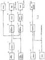
- FIG. 2The block diagram representation of FIG. 2 reveals the basic structure of the electronic control and monitoring device for setting and maintaining the pressure in the pad.
- a pressure transducer 10detects the pressure in the hose 6 or in the pad 7, that is to say on the connecting path between an electric pump 14 and the pad 7.
- the pressure transducer signal amplified via an amplifier 11acts on the one hand on the comparison input of a first comparator 12 and on the other hand the comparison input of a second comparator 21.
- the pressure transducer signalalso reaches the pressure display device 2 for immediate display.
- the comparison input of the second comparator 21is not acted upon directly by the pressure transducer signal, but rather with a pressure value reduced by a fixed ratio.
- the reduction factorlargely determines the sensitivity of the setting of the pressure value in the pad 7, as will be explained later. In practice, it is recommended, but also sufficient, to set the reduction factor to 0.9, i.e. the comparison input of the second comparator 21 is acted upon by a pressure transducer signal reduced in level by 10%.
- the setpoint or setting value of the pressureis set on the switch device 20 by means of the selector button 3, for example to a pressure value of 35 mmHg.
- the electrical signal corresponding to this target valueacts on the target inputs of the comparators 12 and 21.
- a driver 13 for the pump 14is connected downstream of the first comparator 12, while the comparator 21 supplies the control signal for a pulse electronics circuit 22 which excites the reducing valve 23.
- FIG. 2also shows the structure of the power supply part of the overall device. Because of the required precision of the pressure monitoring and the desired very small fluctuation range of the set pressure in the pad 7, a regulated supply part 27 will be required.
- a third comparator 26compares a voltage supplied by a battery 25 against the regulated voltage from the regulator 27 and switches off the battery control display 5 in the event of undervoltage, which can be implemented, for example, by means of a light-emitting diode.
- the pressure input 10is applied to the comparison input by the pressure transducer 10 in accordance with the prerequisites.
- a value of, for example, 0.8 to 0.95is expediently selected for this pressure reduction ratio, but in any case a value which ensures that the reducing valve 23 is reliably opened when switching to a lower pressure level.
- a reduction of approx. 10%, i.e. H. a reduction ratio of about 0.9,has been found to be sufficient and usable.
- the second comparator 21therefore has the task of switching the setting.
- the second comparator 21also represents monitoring for the first comparator 12. If the pressure in the pad 7 exceeds the selected set value of the pressure for any reason by a certain amount, which is determined by the reduction ratio, the second comparator 21 delivers the pulse electronics 22 the signal for opening the reducing valve 23.
- a mechanical valve(not shown) is also provided in the pressure system, which opens automatically at a pressure above 55 mmHg, so that damage to the eye is excluded in any case.
- the oculopressionis gaining greater acceptance in ophthalosurgery, since the previous disadvantages, such as difficult manual pressure control, risk of overpressure, are required. by experienced and trained personnel for surveillance. There will be a higher level of security, relief of the staff and above all an unprecedented effectiveness with a complete automatic pressure maintenance for the oculopression.
Landscapes
- Health & Medical Sciences (AREA)
- Ophthalmology & Optometry (AREA)
- Heart & Thoracic Surgery (AREA)
- Surgery (AREA)
- Engineering & Computer Science (AREA)
- Biomedical Technology (AREA)
- Nuclear Medicine, Radiotherapy & Molecular Imaging (AREA)
- Vascular Medicine (AREA)
- Life Sciences & Earth Sciences (AREA)
- Animal Behavior & Ethology (AREA)
- General Health & Medical Sciences (AREA)
- Public Health (AREA)
- Veterinary Medicine (AREA)
- External Artificial Organs (AREA)
Description
Translated fromGermanDie Erfindung betrifft ein Okulopressionsgerät mit einer an eine Pumpe angeschlossenen und auf dem Auge eines Probanden zu befestigenden Pelotte, wie es beispielsweise aus FR-A 2 395 742 bekannt ist.The invention relates to an oculopression device with a pad connected to a pump and to be attached to the eye of a test subject, as is known, for example, from FR-A 2 395 742.
Die Okulopression dient zur Vorbereitung für die Ophthalmochirurgie, insbesondere bei der Implantation einer Intraokularlinse, wo ein hypotoner Bulbus mit tiefer Vorderkammer gefordert ist. Um den Flüssigkeitsdruck im Auge zu reduzieren, wird eine Pelotte mit einem Band auf dem Auge befestigt und sodann wird die Pelotte mittels eines Pumpballs unter Kontrolle durch ein Manometer aufgepumpt, so daß auf das Auge ein Druck zwischen 25 und 40 mmHg ausgeübt wird. Während der etwa 15 Minuten dauemden Okulopression wird die intraokulare Flüssigkeit allmählich aus dem Auge gedrückt und es entsteht ein sogenanntes "weiches Auge". Beim Nachgeben des Auges dehnt sich die Pelotte aus, was aufgrund des geringen Volumens der Pelotte zu einem Druckabfall führt, der unerwünscht und nachteilig ist. Während der Okulopression ist es also erforderlich, daß der Proband unter ständiger Kontrolle bleibt; der Druck muß wiederholt manuell nachgeregelt werden. Dabei ergeben sich in der Praxis insbesondere bei ungeübtem Personal erhebliche Probleme, da es äußerst schwierig ist, bei dem sehr kleinen Volumen der Pelotte derart niedrige Druckwerte zwischen 25 und 40 mmHg manuell exakt einzustellen. Da bereits bei einem Druck von etwa 55 mmHg eine Schädigung des Auges zu befürchten ist, bedarf die bisher übliche manuelle Handhabung des Pressionsgeräts einer sehr gro- βen ärztlichen Erfahrung, um einerseits eine Schädigung des Auges zu vermeiden und um andererseits während der Okulopression einen ganz konstanten Druck auf dem Auge aufrechtzuerhalten. Wird ein durch das nachgebende Auge verursachter Druckverlust nicht unmittelbar durch Nachpumpen ausgeglichen, so hat dies ein schlechteres Ergebnis der Okulopression zur Folge, was für den Chirurgen eine unliebsame Reduzierung der ihm zur Verfügung stehenden Operationszeit bedeuten kann.The oculopression is used to prepare for ophthalmic surgery, especially when implanting an intraocular lens, where a hypotonic bulb with a deep anterior chamber is required. In order to reduce the fluid pressure in the eye, a pad is attached to the eye with a band and then the pad is inflated by means of a pump ball under the control of a manometer, so that a pressure between 25 and 40 mmHg is exerted on the eye. During the oculopression lasting about 15 minutes, the intraocular fluid is gradually pushed out of the eye and a so-called "soft eye" arises. When the eye gives in, the pad expands, which, due to the small volume of the pad, leads to a pressure drop which is undesirable and disadvantageous. During the oculopression it is therefore necessary that the subject remains under constant control; the pressure must be readjusted manually repeatedly. In practice, considerable problems arise in practice, especially for inexperienced personnel, since it is extremely difficult to precisely set such low pressure values between 25 and 40 mmHg with the very small volume of the pad. Since damage to the eye is to be feared even at a pressure of approximately 55 mmHg, the manual handling of the compression device, which has been customary to date, requires a great deal of medical experience in order to avoid damage to the eye on the one hand and to maintain a constant level during ocular depression on the other To maintain pressure on the eye. If a pressure loss caused by the yielding eye is not immediately compensated for by pumping in, this results in a worse result of the oculopression, which can mean an unpleasant reduction in the operating time available to the surgeon.
Der Erfindung liegt damit die Aufgabe zugrunde, ein Okulopressionsgerät zu schaffen, mit dem sich die Okulopression bei konstantem Druck über im Prinzip beliebig lange Zeiträume ohne Gefahr einer Schädigung des Auges durchführen läßt.The invention is therefore based on the object of providing an oculopression device with which the oculopression can be carried out at constant pressure over, in principle, any length of time without the risk of damage to the eye.
Ein erfindungsgemäßes Okulopressionsgerät der eingangs genannten Art weist die im kennzeichnenden Teil des Patentanspruchs 1 angegebenen Merkmale auf.An oculopression device according to the invention of the type mentioned at the outset has the features specified in the characterizing part of patent claim 1.
Bei einem aus der Druckschrift EP-A 0 180 317 bekannten chirurgischen Gerät zur operativen Entfernung von Wucherungen im Augeninneren ist zwar eine mikroprozessorgesteuerte Drucküberwachungseinrichtung vorgesehen, die über eine beispielsweise in die Augenvorkammer zu stechende Hohlnadel eine unter dem erwünschten Augeninnendruck gehaltene physiologische Kochsalzlösung in das Augeninnere drückt.In a surgical device known from the document EP-
Die Salzlösung wird unter der Wirkung eine Peristaltikpumpe in einem Umlaufsystem durch Regelung . der Drehzahl der Pumpe auf dem erwünschten konstanten Druck gehalten. Sinkt der über die Hohlnadel im Augeninneren erfaßte Druck ab, so wird die Pumpleistung erhöht, bei ansteigendem Augeninnendruck dagegen erniedrigt. Bei diesem bekannten Augenoperationsgerät handelt es sich jedoch um ein insgesamt aufwendiges System, bei dem der unmittelbar im Augeninneren gemessene Druck über die Einspeisung bzw. Entnahme von Augenflüssigkeit/Salzlösung indirekt über die Regulierung der Drehzahl eines Pumpensystems konstant gehalten bzw. auf gewünschte Werte geregelt wird. Abgesehen davon, daß in EP-A 0 180 317 nicht beschrieben ist, welche Regelkriterien für das umlaufende Medium (Kochsalzlösung) gelten und wie die Regeleinrichtung zu gestalten wäre, kommt für den hier vorgesehenen Zweck der Okulopression ein aufwendiges Regelsystem mit umlaufendem Medium kaum in Frage.The saline solution is controlled by a peristaltic pump in a circulating system. the speed of the pump is kept at the desired constant pressure. If the pressure sensed via the hollow needle in the interior of the eye drops, the pumping capacity is increased, but decreases with increasing intraocular pressure. However, this known eye surgery device is an overall complex system in which the pressure measured directly in the interior of the eye via the supply or withdrawal of eye fluid / saline solution is indirectly kept constant or regulated to desired values by regulating the speed of a pump system. In addition to the fact that EP-
Wie bei bekannten Okulopressionsgeräten auch, wird bei der erfindungsgemäßen Verbesserung zunächst eine bekannte und übliche Pelotte mittels eines um den Kopf des Probanden geschlungenen Bandes auf dem Auge befestigt. Sodann wird schalterbetätigt die Pumpe mit angeschlossener Pelotte in Betrieb gesetzt, bis der Sollwert erreicht ist. Sinkt der Druck in der Pelotte bei sich langsam entleerendem Auge ab, wird also der Sollwert geringfügig unterschritten, so wird die Pumpe wieder eingeschaltet, bis das Drucksignal vom Druckwandler den Sollwert beispielsweise 30 mmHg, wieder erreicht. Der andere Komparator ist eingangsseitig einerseits mit dem Sollwert und andererseits mit einem um ein festes Verhältnis reduzierten Anteil (z. B. 0,9) oder einem festen, 3 bis 4 mmHg entsprechenden geringeren Betrag des Druckwandlersignals beaufschlagt und liefert ausgangsseitig ein Steuersignal an das Reduzierventil, sobald der Druck in der Pelotte den Sollwert beispielsweise bei gestörtem ersten Komparator um den Differenzwert zwischen Sollwert und dem reduzierten Drucksignal überschreitet.As with known oculopression devices, in the improvement according to the invention a known and customary pad is first fastened to the eye by means of a strap which is wrapped around the subject's head. The pump is then operated by a switch with the pad attached until the setpoint is reached. If the pressure in the pad drops while the eye is slowly emptying, i.e. if the setpoint is slightly undercut, the pump is switched on again until the pressure signal from the pressure transducer again reaches the setpoint, for example 30 mmHg. On the input side, the other comparator is supplied with the setpoint on the one hand and, on the other hand, with a proportion reduced by a fixed ratio (e.g. 0.9) or a fixed amount of the pressure transducer signal corresponding to 3 to 4 mmHg and supplies a control signal to the reducing valve on the output side , as soon as the pressure in the pad exceeds the setpoint, for example with a disturbed first comparator, by the difference between the setpoint and the reduced pressure signal.
Dies ist selbstverständlich auch der Fall, wenn der Druck in der Pelotte und damit der Druck auf das Auge beispielsweise auf 25 mmHg reduziert werden soll.Of course, this is also the case if the pressure in the pad and thus the pressure on the eye is to be reduced to 25 mmHg, for example.
Die Erfindung und vorteilhafte Einzelheiten werden nachfolgend unter Bezug auf die Zeichnung anhand eines Ausführungsbeispiels näher erläutert. Es zeigen:
- Fig. 1 die (schematische) Frontansicht eines Okulopressionsgeräts gemäß der Erfindung, und
- Fig. 2 den prinzipiellen schaltungstechnischen Aufbau des Geräts nach Fig. 1.
- Fig. 1 is the (schematic) front view of an oculopression device according to the invention, and
- 2 shows the basic circuit design of the device according to FIG. 1.
Von der Außenseite wird ein Okulopressionsgerät 1 mit erfindungsgemäßen Merkmalen mit einem Druckanzeigeinstrument 2 versehen sein, auf dessen Skala die für die Okulopression üblichen Druckwerte anzeigbar sind. An einem Wahlschalter 3 einer zur Druckvorwahl bestimmten Schaltereinrichtung 20 können bestimmte Drucksollwerte 4 in üblicher Weise gewünschten Druckwertstufen zwischen beispielsweise 25 und 40 mmHg vorgewählt werden. Eine Lichtanzeige 5 dient zur Anzeige der Betriebsbereitschaft bzw. zur Kontrolle des Ladezustands einer Batterie, da es für die universelle Einsatzbereitschaft des Geräts zweckmäßig sein wird,sowohl Netzbetrieb als auch Batteriebetrieb vorzusehen. An einem Druckluftauslaß 9 kann über einen Verbindungsschlauch 6 eine übliche Pelotte 7 angeschlossen werden, die in bekannter Weise mittels eines (nicht gezeigten) Bandes über einen Ansatz 8 auf dem Auge befestigt werden kann.From the outside, an oculopression device 1 with features according to the invention will be provided with a
Die Blockschaltbilddarstellung der Fig. 2 läßt den prinzipiellen Aufbau der elektronischen Steuer-und Überwachungseinrichtung zur Einstellung und Konstanthaltung des Drucks in der Pelotte erkennen.The block diagram representation of FIG. 2 reveals the basic structure of the electronic control and monitoring device for setting and maintaining the pressure in the pad.
Ein Druckwandler 10 erfaßt den Druck im Schlauch 6 bzw. in der Pelotte 7, also auf dem Verbindungsweg zwischen einer elektrischen Pumpe 14 und der Pelotte 7. Das über einen Verstärker 11 verstärkte Druckwandlersignal beaufschlagt einerseits den Vergleichseingang eines ersten Komparators 12 und andererseits den Vergleichseingang eines zweiten Komparators 21. Zur unmittelbaren Anzeige gelangt das Druckwandlersignal außerdem auf die Druckanzeigeeinrichtung 2. Der Vergleichseingang des zweiten Komparators 21 wird jedoch nicht durch das Druckwandlersignal unmittelbar, sondern mit einem um ein fest eingestelltes Verhältnis reduzierten Druckwert beaufschlagt. Der Reduktionsfaktor bestimmt zu einem wesentlichen Teil die Empfindlichkeit der Einstellung des Druckwerts in der Pelotte 7, wie noch später erläutert werden wird. Für die Praxis zeigt es sich als empfehlenswert, aber auch als ausreichend, den Reduktionsfaktor auf 0.9 einzustellen, d.h. der Vergleichseingang des zweiten Komparators 21 wird mit einem um 10 % im Pegel reduzierten Druckwandlersignal beaufschlagt.A
Der Soll- oder Einstellwert des Drucks wird an der Schaltereinrichtung 20 mittels des Wählknopfs 3 eingestellt, beispielsweise auf einen Druckwert von 35 mmHg. Das diesem Sollwert entsprechende elektrische Signal beaufschlagt die Solleingänge der Komparatoren 12 und 21.The setpoint or setting value of the pressure is set on the
Dem ersten Komparator 12 ist ein Treiber 13 für die Pumpe 14 nachgeschaltet, während der Komparator 21 das Ansteuersignal für eine Impulselektronikschaltung 22 liefert, die das Reduzierventil 23 erregt.A
Der Vollständigkeit halber ze igt die Fig. 2 noch den Aufbau des Stromversorgungsteils des Gesamtgeräts. Wegen der erforderlichen Präzision der Drucküberwachung und der erwünschten sehr kleinen Schwankungsbreite des eingestellten Drucks in der Pelotte 7 wird ein geregeltes Versorgungsteil 27 erforderlich sein. Ein dritter Komparator 26 vergleicht eine von einer Batterie 25 gelieferte Spannung gegen die geregelte Spannung vom Regler 27 und schaltet bei Unterspannung die Batteriekontrollanzeige 5 aus, die beispielsweise mittels einer lichtemittierenden Diode verwirklicht sein kann.For the sake of completeness, FIG. 2 also shows the structure of the power supply part of the overall device. Because of the required precision of the pressure monitoring and the desired very small fluctuation range of the set pressure in the
Die Schaltung nach Fig. 2 arbeitet wie folgt:
- Solange in der Pelotte 7 ein an der Druckvorwahl-
Schaltereinrichtung 20 eingestellter Druckwert noch nicht erreicht ist, liefert derKomparator 12 über denTreiber 13 ein Erregersignal an diePumpe 14, die damit den Druck in derPelotte 7 erhöht. Sobald das vomDruckwandler 10 gelieferte Drucksignal den eingestellten Sollwert des Drucks erreicht, sperrt dererste Komparator 12 denTreiber 14, so daß diePumpe 14 abgeschaltet wird. Wird das unter dem Überdruck der Pelotte 7 stehende Auge allmählich weich, so sinkt das Drucksignal ab und dererste Komparator 12 schaltet diePumpe 14 wieder so lange ein, bis der an derSchaltereinrichtung 20 eingestellte Sollwert wieder erreicht ist. Auf diese Weise kann der Druck auf das Auge innerhalb eines Schwankungsbereichs von maximal ± 2 mmHg konstant gehalten werden.
- As long as a pressure value set on the pressure
preselection switch device 20 has not yet been reached in thepad 7, thecomparator 12 supplies an excitation signal to thepump 14 via thedriver 13, which thus increases the pressure in thepad 7. As soon as the pressure signal supplied by thepressure transducer 10 reaches the setpoint value of the pressure, thefirst comparator 12 blocks thedriver 14 so that thepump 14 is switched off. If the eye under the excess pressure of thepad 7 gradually becomes soft, the pressure signal drops and thefirst comparator 12 switches thepump 14 on again until the setpoint set on theswitch device 20 is reached again. In this way, the pressure on the eye can be kept constant within a maximum fluctuation range of ± 2 mmHg.
Am Solleingang des zweiten Komparators 21 liegt einerseits das Druckvorwahlsignal von der Schaltereinrichtung 20, während den Vergleichseingang andererseits voraussetzungsgemäß der in einem festgelegten Verhältnis oder um einen festgelegten Betrag untersetzte Druckwert vom Druckwandler 10 beaufschlagt. Für dieses Druckuntersetzungsverhältnis wird zweckmäßigerweise ein Wert von beispielsweise 0,8 bis 0,95 gewählt, in jedem Fall aber ein Wert, der bei Umschaltung auf eine niedrigere Druckstufe eine sichere Öffnung des Reduzierventils 23 gewährleistet. In der Praxis hat sich eine Reduzierung ca. 10 %, d. h. ein Untersetzungsverhältnis von ca. 0,9, als ausreichend und brauchbar erwiesen. Der zweite Komparator 21 hat also einerseits die Aufgabe, bei Umschaltung des Setz- . werts der Druckvorwahl das Reduzierventil 23 so lange zu öffnen, wie der Druck in der Pelotte den neu eingestellten Sollwert um den Differenzwert zwischen diesem Sollwert und dem reduzierten Drucksignal überschreitet. Selbstverständlich wird die vollständige Entleerung der Pelotte bei Abschaltung des Geräts ebenfalls über das Reduzierventil 23 erfolgen. Der zweite Komparator 21 stellt aber andererseits auch eine Überwachung für den ersten Komparator 12 dar. Denn übersteigt der Druck in der Pelotte 7 den gewählten Setzwert des Druck aus irgendeinem Grund um einen bestimmten, durch das Reduzierverhältnis festgelegten Betrag, so liefert der zweite Komparator 21 über die Impulselektronik 22 das Signal zum Öffnen des Reduzierventils 23.At the setpoint input of the
Zur zusätzlichen Sicherheit für das Auge gegen Überdruck im Falle eines vollständigen Defekts der Elektronik, d.h. bei eventuellem Dauerlauf der Pumpe 14 oder bei Versagen des elektromagnetischen Reduzierventils 23 ist im Drucksystem außerdem noch ein (nicht gezeigtes) mechanisches Ventil vorgesehen, das bei einem Druck ab 55 mmHg automatisch öffnet, so daß eine Schädigung des Auges in jedem Fall ausgeschlossen ist.For additional safety for the eye against excess pressure in the event of a complete defect in the electronics, i.e. If the
Durch die Erfindung wird die Okulopression eine größere Akzeptanz in der Ophthalochirurgie erhalten, da die bisherigen Nachteile, wie schwierige manuelle Druckregelung, Überdruckgefahr, Bedarf . von erfahrenem und geschultem Personal zur Überwachung, beseitigt sind. Es wird eine höhere Sicherheit, Entlastung des Personals und vor allem eine bisher nicht erzielte Wirksamkeit mit einer vollkommen automatischen Druckkonstanthaltung für die Okulopression erreicht.By means of the invention, the oculopression is gaining greater acceptance in ophthalosurgery, since the previous disadvantages, such as difficult manual pressure control, risk of overpressure, are required. by experienced and trained personnel for surveillance. There will be a higher level of security, relief of the staff and above all an unprecedented effectiveness with a complete automatic pressure maintenance for the oculopression.
Claims (7)
Priority Applications (2)
| Application Number | Priority Date | Filing Date | Title |
|---|---|---|---|
| EP19860115357EP0266451B1 (en) | 1986-11-05 | 1986-11-05 | Instrument for reducing intra-ocular pressure |
| DE8686115357TDE3669032D1 (en) | 1986-11-05 | 1986-11-05 | OKULOPRESSIONSGERAET. |
Applications Claiming Priority (1)
| Application Number | Priority Date | Filing Date | Title |
|---|---|---|---|
| EP19860115357EP0266451B1 (en) | 1986-11-05 | 1986-11-05 | Instrument for reducing intra-ocular pressure |
Publications (2)
| Publication Number | Publication Date |
|---|---|
| EP0266451A1 EP0266451A1 (en) | 1988-05-11 |
| EP0266451B1true EP0266451B1 (en) | 1990-02-14 |
Family
ID=8195572
Family Applications (1)
| Application Number | Title | Priority Date | Filing Date |
|---|---|---|---|
| EP19860115357Expired - LifetimeEP0266451B1 (en) | 1986-11-05 | 1986-11-05 | Instrument for reducing intra-ocular pressure |
Country Status (2)
| Country | Link |
|---|---|
| EP (1) | EP0266451B1 (en) |
| DE (1) | DE3669032D1 (en) |
Families Citing this family (4)
| Publication number | Priority date | Publication date | Assignee | Title |
|---|---|---|---|---|
| WO1995019749A2 (en)* | 1994-01-21 | 1995-07-27 | Propper Manufacturing Co., Inc. | Oculopressive device and method |
| US5601548A (en)* | 1994-11-07 | 1997-02-11 | Ophthalmic International, L.L.C. | Open angle glaucoma treatment apparatus and method |
| CA3057786C (en) | 2011-12-08 | 2022-02-08 | Alcon Research, Ltd. | Selectively moveable valve elements for aspiration and irrigation circuits |
| US9549850B2 (en) | 2013-04-26 | 2017-01-24 | Novartis Ag | Partial venting system for occlusion surge mitigation |
Family Cites Families (3)
| Publication number | Priority date | Publication date | Assignee | Title |
|---|---|---|---|---|
| US3527204A (en)* | 1965-05-28 | 1970-09-08 | Ibm | Pressure cuff system |
| US4175562A (en)* | 1977-06-30 | 1979-11-27 | Honan Paul R | Intraocular pressure applicator |
| US4722350A (en)* | 1984-09-21 | 1988-02-02 | Armeniades C D | Ophthalmic instrument for measuring intraocular fluid pressure |
- 1986
- 1986-11-05EPEP19860115357patent/EP0266451B1/ennot_activeExpired - Lifetime
- 1986-11-05DEDE8686115357Tpatent/DE3669032D1/ennot_activeExpired - Lifetime
Also Published As
| Publication number | Publication date |
|---|---|
| EP0266451A1 (en) | 1988-05-11 |
| DE3669032D1 (en) | 1990-03-22 |
Similar Documents
| Publication | Publication Date | Title |
|---|---|---|
| DE69528659T2 (en) | PHYSIOLOGICAL TOURNIQUET | |
| EP0626151B1 (en) | Compression apparatus for creating a bloodless condition in the extremities | |
| DE69413680T2 (en) | AUTOMATIC BLOOD RETAINING CUFF | |
| DE69534453T2 (en) | SYSTEM FOR CORONARY VESSEL PLASTIC | |
| DE69027430T2 (en) | METHOD AND DEVICE FOR OCULAR PERFUSION | |
| DE69600227T2 (en) | Process control system | |
| US4157718A (en) | Intra-ocular pressure normalization technique and equipment | |
| US4184491A (en) | Intra-ocular pressure normalization technique and equipment | |
| DE3143421A1 (en) | Laser scalpel | |
| EP0717970A1 (en) | Opthalmic aspiration and irrigation device and its operation procedure | |
| DE3133259A1 (en) | PNEUMATIC TOURNIQUET | |
| EP2905038B1 (en) | Determining the size of the air fistula in thoracic drainage treatment | |
| DE2506652A1 (en) | BLOOD PRESSURE MONITOR | |
| DE1061480B (en) | Device for automatic blood pressure monitoring | |
| EP0266451B1 (en) | Instrument for reducing intra-ocular pressure | |
| EP1125554B1 (en) | Vein occluding apparatus | |
| EP3295906A1 (en) | System for performing a phacoemulsification | |
| DE3116387A1 (en) | BLOOD PRESSURE MEASURING DEVICE | |
| DE3000218C2 (en) | Apparatus for insufflating flowable media | |
| DE69323575T2 (en) | Automatic sphygmomanometer | |
| EP1519701A1 (en) | Device for measuring and monitoring the fractional load of orthopaedic and surgical patents | |
| EP2621421B1 (en) | Device for eye surgery | |
| DE9203788U1 (en) | Shoe insole for ulcer prophylaxis on the diabetic foot | |
| DE3716230C2 (en) | ||
| DE102018130376B4 (en) | Method of controlling an ophthalmic surgical handpiece, ophthalmic surgical apparatus and system |
Legal Events
| Date | Code | Title | Description |
|---|---|---|---|
| PUAI | Public reference made under article 153(3) epc to a published international application that has entered the european phase | Free format text:ORIGINAL CODE: 0009012 | |
| 17P | Request for examination filed | Effective date:19870902 | |
| AK | Designated contracting states | Kind code of ref document:A1 Designated state(s):BE CH DE FR GB IT LI SE | |
| 17Q | First examination report despatched | Effective date:19880810 | |
| GRAA | (expected) grant | Free format text:ORIGINAL CODE: 0009210 | |
| AK | Designated contracting states | Kind code of ref document:B1 Designated state(s):BE CH DE FR GB IT LI SE | |
| REF | Corresponds to: | Ref document number:3669032 Country of ref document:DE Date of ref document:19900322 | |
| ET | Fr: translation filed | ||
| ITF | It: translation for a ep patent filed | ||
| GBT | Gb: translation of ep patent filed (gb section 77(6)(a)/1977) | ||
| PG25 | Lapsed in a contracting state [announced via postgrant information from national office to epo] | Ref country code:GB Effective date:19901105 | |
| PG25 | Lapsed in a contracting state [announced via postgrant information from national office to epo] | Ref country code:SE Effective date:19901106 | |
| PG25 | Lapsed in a contracting state [announced via postgrant information from national office to epo] | Ref country code:LI Effective date:19901130 Ref country code:CH Effective date:19901130 Ref country code:BE Effective date:19901130 | |
| PLBE | No opposition filed within time limit | Free format text:ORIGINAL CODE: 0009261 | |
| STAA | Information on the status of an ep patent application or granted ep patent | Free format text:STATUS: NO OPPOSITION FILED WITHIN TIME LIMIT | |
| 26N | No opposition filed | ||
| BERE | Be: lapsed | Owner name:BOSCH + SOHN G.M.B.H. U. CO. K.G. FABRIK MEDIZINI Effective date:19901130 | |
| GBPC | Gb: european patent ceased through non-payment of renewal fee | ||
| PG25 | Lapsed in a contracting state [announced via postgrant information from national office to epo] | Ref country code:FR Effective date:19910731 | |
| REG | Reference to a national code | Ref country code:CH Ref legal event code:PL | |
| PG25 | Lapsed in a contracting state [announced via postgrant information from national office to epo] | Ref country code:DE Effective date:19910801 | |
| REG | Reference to a national code | Ref country code:FR Ref legal event code:ST | |
| EUG | Se: european patent has lapsed | Ref document number:86115357.5 Effective date:19910705 | |
| PG25 | Lapsed in a contracting state [announced via postgrant information from national office to epo] | Ref country code:IT Free format text:LAPSE BECAUSE OF NON-PAYMENT OF DUE FEES;WARNING: LAPSES OF ITALIAN PATENTS WITH EFFECTIVE DATE BEFORE 2007 MAY HAVE OCCURRED AT ANY TIME BEFORE 2007. THE CORRECT EFFECTIVE DATE MAY BE DIFFERENT FROM THE ONE RECORDED. Effective date:20051105 |