EP0265798B1 - A magnetoresistive read transducer - Google Patents
A magnetoresistive read transducerDownload PDFInfo
- Publication number
- EP0265798B1 EP0265798B1EP87115179AEP87115179AEP0265798B1EP 0265798 B1EP0265798 B1EP 0265798B1EP 87115179 AEP87115179 AEP 87115179AEP 87115179 AEP87115179 AEP 87115179AEP 0265798 B1EP0265798 B1EP 0265798B1
- Authority
- EP
- European Patent Office
- Prior art keywords
- layer
- transducer
- magnetoresistive layer
- bias
- end regions
- Prior art date
- Legal status (The legal status is an assumption and is not a legal conclusion. Google has not performed a legal analysis and makes no representation as to the accuracy of the status listed.)
- Expired - Lifetime
Links
- 230000005291magnetic effectEffects0.000claimsdescription30
- 239000004020conductorSubstances0.000claimsdescription18
- 239000010409thin filmSubstances0.000claimsdescription11
- 239000000696magnetic materialSubstances0.000claimsdescription8
- 230000035945sensitivityEffects0.000claimsdescription7
- 239000002885antiferromagnetic materialSubstances0.000claimsdescription3
- 229910001030Iron–nickel alloyInorganic materials0.000claimsdescription2
- 230000001939inductive effectEffects0.000claimsdescription2
- 239000010408filmSubstances0.000description17
- 125000006850spacer groupChemical group0.000description14
- 230000005290antiferromagnetic effectEffects0.000description7
- 230000005415magnetizationEffects0.000description6
- 230000004044responseEffects0.000description5
- 230000001629suppressionEffects0.000description5
- 230000005330Barkhausen effectEffects0.000description4
- 239000000463materialSubstances0.000description4
- 230000004907fluxEffects0.000description3
- 230000002411adverseEffects0.000description2
- 230000008878couplingEffects0.000description2
- 238000010168coupling processMethods0.000description2
- 238000005859coupling reactionMethods0.000description2
- 230000006866deteriorationEffects0.000description2
- 230000003993interactionEffects0.000description2
- 238000000034methodMethods0.000description2
- 230000005316antiferromagnetic exchangeEffects0.000description1
- 230000008901benefitEffects0.000description1
- 238000001514detection methodMethods0.000description1
- 239000000758substrateSubstances0.000description1
Images


Classifications
- G—PHYSICS
- G11—INFORMATION STORAGE
- G11B—INFORMATION STORAGE BASED ON RELATIVE MOVEMENT BETWEEN RECORD CARRIER AND TRANSDUCER
- G11B5/00—Recording by magnetisation or demagnetisation of a record carrier; Reproducing by magnetic means; Record carriers therefor
- G11B5/127—Structure or manufacture of heads, e.g. inductive
- G11B5/33—Structure or manufacture of flux-sensitive heads, i.e. for reproduction only; Combination of such heads with means for recording or erasing only
- G11B5/39—Structure or manufacture of flux-sensitive heads, i.e. for reproduction only; Combination of such heads with means for recording or erasing only using magneto-resistive devices or effects
- G11B5/3903—Structure or manufacture of flux-sensitive heads, i.e. for reproduction only; Combination of such heads with means for recording or erasing only using magneto-resistive devices or effects using magnetic thin film layers or their effects, the films being part of integrated structures
- G11B5/399—Structure or manufacture of flux-sensitive heads, i.e. for reproduction only; Combination of such heads with means for recording or erasing only using magneto-resistive devices or effects using magnetic thin film layers or their effects, the films being part of integrated structures with intrinsic biasing, e.g. provided by equipotential strips
Definitions
- This inventionrelates to a magnetoresistive transducer for reading information signals from a magnetic record medium.
- An MR sensordetects magnetic field signals through the resistance changes of a read element made from a magnetoresistive material as a function of the amount and direction of magnetic flux being sensed by the element.
- EP -A- 0 216 062discloses how patterned longitudinal bias may be used to overcome the aforementioned problems. More particularly, a longitudinal bias is produced in the end regions only of the MR layer to maintain the end regions in a single domain state and these single domain states induce a single domain state in the central region of the MR layer.
- a thin film of soft magnetic materialis provided parallel to, but spaced from, the MR layer to also produce a transverse bias in the central region only of the MR layer to maintain the central region, where the output signal is sensed, in a linear response mode. The introduction of the soft magnetic material may, however, give rise to some problems.
- This inventionseeks to maintain the magnetization within the passive end regions of a MR sensor in a single domain state, so as to keep at a constant value the magnetic flux entering the central active region of the MR sensor from the passive end regions.
- the inventionprovides a magnetoresistive read transducer comprising: a thin magnetoresistive layer, a nonmagnetic decoupling layer covering the magnetoresistive layer; a thin film of soft magnetic material covering the decoupling layer; longitudinal-bias producing means for producing a longitudinal bias directly in only end regions of the magnetoresistive layer of a level sufficient to maintain the end regions of the magnetoresistive layer in a single domain state, the single domain states of the end regions thereby inducing a single domain state in the central region; a pair of conductors electrically connected to opposite ends of said central region of the magnetoresistive layer; and means for supplying a bias current to the pair of conductors to magnetically bias the magnetoresistive layer with transverse bias of a level sufficient to maintain the magnetoresistive layer in a high sensitivity condition whereby, upon connection of the pair of conductors to a signal sensing means, the signal sensing means determines the resistance changes in the magnetoresistive layer as a function of the fields which are intercepted by
- a known magnetic read head 11incorporates a magnetoresistive (MR) sensor 10 (Fig. 1) having three regions, an active region 14 where actual sensing of data is accomplished, and end regions 12. The regions are biased in different ways with longitudinal bias only in the end regions 12 and transverse bias in the active region 14.
- the longitudinal biasis produced by an antiferromagnetic exchange bias layer 15 which is deposited in direct physical contact with MR layer 10.
- the transverse biasis produced by soft magnetic film layer 16 which is separated from MR layer 10 by a thin nonmagnetic spacer layer 17 whose purpose is to prevent, within the active central region, a magnetic exchange coupling between the MR layer 10 and the soft magnetic film layer 16.
- the distance between the inner edges of conductors 18 and 19comprises the detection region over which the output signal is sensed.
- This sensoris based on the premise that with the end regions 12 in a single domain state, the central region 14 is forced into a single domain state so long as the longitudinally unbiased central region is not too long in comparison to the height of the sensor.
- This sensor designhas been demonstrated to provide much more stable operating characteristics and better suppression of Barkhausen noise than designs without exchange biasing provisions, while at the same time not to adversely affect sensor sensitivity as with designs having continuous exchange bias over the active and passive MR sensor segments.
- a magnetic read head assembly 20 embodying the inventioncomprises a magnetoresistive (MR) sensor 22, which is provided with longitudinal bias for domain suppression applied only to the end regions 24 and is provided with transverse bias for a linear response mode only in the central region 26.
- the active read region, over which the output signal is sensed,corresponds to the part of the central region 26 which is provided with transverse bias.
- the MR sensor 22is first deposited over both end regions 24 and central region 26.
- Thin nonmagnetic spacer layer 28is deposited only in the central region 26 and soft magnetic film layer 30 is deposited over both the end regions 24 and the central region 26.
- the soft magnetic film layer 30is separated from MR sensor 22 in the central region 26 by thin spacer layer 28 so that a transverse bias can be produced only in the central region 26 of the MR sensor 22 to produce a linear response mode in MR sensor 22.
- the MR sensor 22is shown as deposited first in Fig. 2, soft magnetic film layer 30 could as well be deposited first, followed by thin spacer layer 28 and then by the MR sensor 22.
- An antiferromagnetic layer 32is deposited over the soft magnetic film layer 30 only in the end regions 24.
- Antiferromagnetic layer 32creates an interfacial exchange interaction with the soft magnetic film layer 30 that results in an effective bias field experienced by soft magnetic film layer 30 and also by the MR sensor 22 which is in contact with the soft magnetic film layer 30.
- the resulting bias fieldis oriented longitudinally for domain suppression as is shown in Fig. 4.
- Conductor leads 34 and 36, over which the output signal is sensed,are deposited only in the end regions 24 over the antiferromagnetic layer 32.
- a bias current source 35is connected between conductor leads 34 and 36 to produce a bias current in the central region 26 of the MR sensor 22 to magnetically bias the MR sensor with transverse bias.
- the transverse biasis produced in that part of the central region 26 of the MR sensor 22 in which the bias current and the thin spacer layer 28 are both present.
- the transverse biasproduces magnetization at a chosen angle, as shown in Fig. 4, in the central region 26 of the MR sensor 22 so that the MR sensor 22 is maintained in a high sensitivity condition.
- the transverse biasis provided in a central active region Ra.
- the MR layer 22 ⁇is deposited as before, but, in this embodiment, the extent of the thin nonmagnetic spacer layer 28 ⁇ is less than the distance between the inner edges of the conductor leads 34 ⁇ and 36 ⁇ and antiferromagnetic layer 32 ⁇ .
- the central active region Rais again defined by the extent of the MR sensor within the central region in which a bias current and thin spacer layer 28 ⁇ are present.
- the position of the MR sensor 22 ⁇ and the soft magnetic film layer 30 ⁇can be reversed, if desired.
- FIG. 5A further embodiment of the MR read transducer assembly is shown in FIG. 5 in which the MR read transducer assembly has a sensing edge 56 which is closely spaced from the magnetic medium during normal operation.
- the MR element 58is shaped so that only the active central region 60 of the sensor extends to the sensing edge.
- the active region (shown shaded in the drawing) 60is defined by the extent of the spacer member in common with the embodiment shown in Fig. 3.
- the end regions 62 of the MR element 58are tapered to become wider with increasing distance from the central region and tilted away from the sensing edge, and conductor leads 64 and 66 are in contact with the end regions 62 away from the sensing edge.
- the embodiment of the MR read transducer assembly shown in FIG. 5has the advantage of less sensitivity to its operating environment since only the central region of the MR element extends to the sensing edge.
- the fact that the conductor leads do not extend to the sensing edgeeases mechanical problems, and the tapering and tilting of the MR sensor in the end regions leads to reduced side reading. Since any deterioration of the MR sensor/conductor lead electrical contact adversely affects the sensitivity profile, this design prevents deterioration since the electrical contact is not exposed at the sensing edge.
- a magnetic read head 120incorporates an MR sensor 122 provided with longitudinal bias for domain suppression only in its end regions 124 and with transverse bias for a linear response mode only in its central region 126.
- the active read region Raover which the output signal is sensed, corresponds to the part of the central region 126 which is provided with transverse bias.
- the MR sensor 122is first deposited over both end regions 124 and central region 126.
- a spacer layer 128is formed only over the central region 126 of the MR sensor layer 122 and a soft magnetic film layer 130 is formed only over the spacer layer 128 so that a transverse bias can be produced only in the central region 126 of the MR sensor 122 to produce a linear response mode in MR sensor 122.
- An antiferromagnetic layer 132is formed only in the end regions of MR sensor layer 122. Antiferromagnetic layer 132 creates an interfacial exchange interaction with the MR sensor 122 that results in an effective bias field experienced by the MR sensor 122, and this bias field is oriented longitudinally for domain suppression.
- Conductor leads 134 and 136, over which the output signal is sensed,are deposited only on the antiferromagnetic layer 132, i.e. only over the end regions 124 of MR sensor layer 122.
- the position of the MR sensor 122 and the soft magnetic film layer 130can be reversed, if desired.
- a bias current source 38is connected between conductor leads 134 and 136 to produce a bias current in the central region 126 of the MR sensor 122 to magnetically bias the MR sensor with transverse bias.
- the transverse biasis produced in that part of the central region 126 of the MR sensor 122 in which the bias current and the spacer layer 128 are both present.
- the transverse biasproduces magnetization at a chosen angle in the central region 126 of the MR sensor 122 so that the MR sensor 122 is maintained in a high sensitivity condition.
- both the soft magnetic film 130 and the spacer layer 128extend only over the central region 126 of the MR sensor 122 in contrast to the arrangement in the known design of Fig. 1 in which the corresponding layers are continuous over the entire length of the MR sensor 10.
- the magnetic read head embodying the present inventionhas a soft film transverse bias exclusively in the active part of the central region of the head since the spacer layer served to break the exchange coupling between the MR sensor and the soft magnetic film.
- the use of the present inventionincreases the range of stable operation relative to the various disturb conditions. It also self-initiates the proper magnetization configuration thereby eliminating the need for device initialisation.
Landscapes
- Engineering & Computer Science (AREA)
- Manufacturing & Machinery (AREA)
- Magnetic Heads (AREA)
Description
- This invention relates to a magnetoresistive transducer for reading information signals from a magnetic record medium.
- An MR sensor detects magnetic field signals through the resistance changes of a read element made from a magnetoresistive material as a function of the amount and direction of magnetic flux being sensed by the element.
- Problems with MR sensors of unstable operating characteristics and Barkhausen noise have limited their use. These problems arise because there generally exists more than one stable state for the magnetization, a degeneracy which typically produces various multi-domain configurations. Random changes in this configuration are the cause of the above-mentioned unstable operating characteristics and Barkhausen noise.
- EP -A- 0 216 062 discloses how patterned longitudinal bias may be used to overcome the aforementioned problems. More particularly, a longitudinal bias is produced in the end regions only of the MR layer to maintain the end regions in a single domain state and these single domain states induce a single domain state in the central region of the MR layer. In a specific embodiment, a thin film of soft magnetic material is provided parallel to, but spaced from, the MR layer to also produce a transverse bias in the central region only of the MR layer to maintain the central region, where the output signal is sensed, in a linear response mode. The introduction of the soft magnetic material may, however, give rise to some problems. Specifically, as a single domain state is induced only in the end regions of the MR layer and the domain state in the end regions of the soft magnetic bias film is left undefined, the total amount of magnetic flux coming in from the passive end regions is still undefined and some unstable operating characteristics and Barkhausen noise may still occur.
- This invention seeks to maintain the magnetization within the passive end regions of a MR sensor in a single domain state, so as to keep at a constant value the magnetic flux entering the central active region of the MR sensor from the passive end regions.
- The invention provides a magnetoresistive read transducer comprising: a thin magnetoresistive layer, a nonmagnetic decoupling layer covering the magnetoresistive layer; a thin film of soft magnetic material covering the decoupling layer; longitudinal-bias producing means for producing a longitudinal bias directly in only end regions of the magnetoresistive layer of a level sufficient to maintain the end regions of the magnetoresistive layer in a single domain state, the single domain states of the end regions thereby inducing a single domain state in the central region; a pair of conductors electrically connected to opposite ends of said central region of the magnetoresistive layer; and means for supplying a bias current to the pair of conductors to magnetically bias the magnetoresistive layer with transverse bias of a level sufficient to maintain the magnetoresistive layer in a high sensitivity condition whereby, upon connection of the pair of conductors to a signal sensing means, the signal sensing means determines the resistance changes in the magnetoresistive layer as a function of the fields which are intercepted by the magnetoresistive layer, characterised in that:- the nomagnetic decoupling layer covers only a central region of the magnetoresistive layer.
- How the invention can be carried out will now be described by way of example, with reference to the accompanying diagrammatic drawings, in which:
- Fig. 1 is an end view of a known magnetoresistive read transducer assembly;
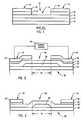
- Fig. 2 is an end view of one magnetoresistive read transducer assembly embodying the present invention;
- Fig. 3 is an end view of another magnetoresistive read transducer assembly embodying the invention;
- Fig. 4 is a exploded perspective view which shows the magnetization configuration of the thin film of soft magnetic material and the MR layer of the magnetic read transducer assembly of Fig. 2;
- FIG. 5 is a plan view of a further magnetoresistive read transducer embodying the invention; and
- Fig. 6 is an end view of another magnetoresistive read transducer assembly embodying the invention.
- A known magnetic read head 11 incorporates a magnetoresistive (MR) sensor 10 (Fig. 1) having three regions, an
active region 14 where actual sensing of data is accomplished, andend regions 12. The regions are biased in different ways with longitudinal bias only in theend regions 12 and transverse bias in theactive region 14. The longitudinal bias is produced by an antiferromagneticexchange bias layer 15 which is deposited in direct physical contact withMR layer 10. The transverse bias is produced by softmagnetic film layer 16 which is separated fromMR layer 10 by a thinnonmagnetic spacer layer 17 whose purpose is to prevent, within the active central region, a magnetic exchange coupling between theMR layer 10 and the softmagnetic film layer 16. The distance between the inner edges ofconductors - The design of this sensor is based on the premise that with the
end regions 12 in a single domain state, thecentral region 14 is forced into a single domain state so long as the longitudinally unbiased central region is not too long in comparison to the height of the sensor. This sensor design has been demonstrated to provide much more stable operating characteristics and better suppression of Barkhausen noise than designs without exchange biasing provisions, while at the same time not to adversely affect sensor sensitivity as with designs having continuous exchange bias over the active and passive MR sensor segments. - With reference to Fig. 2, a magnetic
read head assembly 20 embodying the invention, comprises a magnetoresistive (MR)sensor 22, which is provided with longitudinal bias for domain suppression applied only to theend regions 24 and is provided with transverse bias for a linear response mode only in thecentral region 26. The active read region, over which the output signal is sensed, corresponds to the part of thecentral region 26 which is provided with transverse bias. - The
MR sensor 22 is first deposited over bothend regions 24 andcentral region 26. Thinnonmagnetic spacer layer 28 is deposited only in thecentral region 26 and softmagnetic film layer 30 is deposited over both theend regions 24 and thecentral region 26. The softmagnetic film layer 30 is separated fromMR sensor 22 in thecentral region 26 bythin spacer layer 28 so that a transverse bias can be produced only in thecentral region 26 of theMR sensor 22 to produce a linear response mode inMR sensor 22. Although theMR sensor 22 is shown as deposited first in Fig. 2, softmagnetic film layer 30 could as well be deposited first, followed bythin spacer layer 28 and then by theMR sensor 22. Anantiferromagnetic layer 32 is deposited over the softmagnetic film layer 30 only in theend regions 24.Antiferromagnetic layer 32 creates an interfacial exchange interaction with the softmagnetic film layer 30 that results in an effective bias field experienced by softmagnetic film layer 30 and also by theMR sensor 22 which is in contact with the softmagnetic film layer 30. The resulting bias field is oriented longitudinally for domain suppression as is shown in Fig. 4. Conductor leads 34 and 36, over which the output signal is sensed, are deposited only in theend regions 24 over theantiferromagnetic layer 32. - A bias
current source 35 is connected between conductor leads 34 and 36 to produce a bias current in thecentral region 26 of theMR sensor 22 to magnetically bias the MR sensor with transverse bias. The transverse bias is produced in that part of thecentral region 26 of theMR sensor 22 in which the bias current and thethin spacer layer 28 are both present. The transverse bias produces magnetization at a chosen angle, as shown in Fig. 4, in thecentral region 26 of theMR sensor 22 so that theMR sensor 22 is maintained in a high sensitivity condition. In the embodiment shown in Fig. 2, the transverse bias is provided in a central active region Ra. - In the embodiment of Fig. 3, the MR layer 22ʹ is deposited as before, but, in this embodiment, the extent of the thin nonmagnetic spacer layer 28ʹ is less than the distance between the inner edges of the conductor leads 34ʹ and 36ʹ and antiferromagnetic layer 32ʹ. The central active region Ra is again defined by the extent of the MR sensor within the central region in which a bias current and thin spacer layer 28ʹ are present. In common with the embodiment shown in Fig. 2, the position of the MR sensor 22ʹ and the soft magnetic film layer 30ʹ can be reversed, if desired.
- A further embodiment of the MR read transducer assembly is shown in FIG. 5 in which the MR read transducer assembly has a
sensing edge 56 which is closely spaced from the magnetic medium during normal operation. In this embodiment theMR element 58 is shaped so that only the activecentral region 60 of the sensor extends to the sensing edge. The active region (shown shaded in the drawing) 60 is defined by the extent of the spacer member in common with the embodiment shown in Fig. 3. Theend regions 62 of theMR element 58 are tapered to become wider with increasing distance from the central region and tilted away from the sensing edge, and conductor leads 64 and 66 are in contact with theend regions 62 away from the sensing edge. - The embodiment of the MR read transducer assembly shown in FIG. 5 has the advantage of less sensitivity to its operating environment since only the central region of the MR element extends to the sensing edge. The fact that the conductor leads do not extend to the sensing edge eases mechanical problems, and the tapering and tilting of the MR sensor in the end regions leads to reduced side reading. Since any deterioration of the MR sensor/conductor lead electrical contact adversely affects the sensitivity profile, this design prevents deterioration since the electrical contact is not exposed at the sensing edge.
- In the embodiment of Fig. 6, a
magnetic read head 120 incorporates anMR sensor 122 provided with longitudinal bias for domain suppression only in itsend regions 124 and with transverse bias for a linear response mode only in itscentral region 126. The active read region Ra, over which the output signal is sensed, corresponds to the part of thecentral region 126 which is provided with transverse bias. - The
MR sensor 122 is first deposited over bothend regions 124 andcentral region 126. Aspacer layer 128 is formed only over thecentral region 126 of theMR sensor layer 122 and a softmagnetic film layer 130 is formed only over thespacer layer 128 so that a transverse bias can be produced only in thecentral region 126 of theMR sensor 122 to produce a linear response mode inMR sensor 122. Anantiferromagnetic layer 132 is formed only in the end regions ofMR sensor layer 122.Antiferromagnetic layer 132 creates an interfacial exchange interaction with theMR sensor 122 that results in an effective bias field experienced by theMR sensor 122, and this bias field is oriented longitudinally for domain suppression. Conductor leads 134 and 136, over which the output signal is sensed, are deposited only on theantiferromagnetic layer 132, i.e. only over theend regions 124 ofMR sensor layer 122. The position of theMR sensor 122 and the softmagnetic film layer 130 can be reversed, if desired. - A bias
current source 38 is connected between conductor leads 134 and 136 to produce a bias current in thecentral region 126 of theMR sensor 122 to magnetically bias the MR sensor with transverse bias. The transverse bias is produced in that part of thecentral region 126 of theMR sensor 122 in which the bias current and thespacer layer 128 are both present. The transverse bias produces magnetization at a chosen angle in thecentral region 126 of theMR sensor 122 so that theMR sensor 122 is maintained in a high sensitivity condition. - Note that both the soft
magnetic film 130 and thespacer layer 128 extend only over thecentral region 126 of theMR sensor 122 in contrast to the arrangement in the known design of Fig. 1 in which the corresponding layers are continuous over the entire length of theMR sensor 10. - A magnetic read head embodying the present invention can be fabricated by any suitable method known to those skilled in the art. In a specific embodiment, a thin film of a suitable MR material such as NiFe, a patterned thin film spacer layer of a suitable material such as Ta, a soft magnetic film layer of a suitable material such as NiFeRh, a layer of antiferromagnetic material such as MnFe, and conductive leads are deposited upon a suitable substrate in successive layers which are appropriately patterned using lithographic thin film processing techniques known to those skilled in the art.
- It can be seen that the magnetic read head embodying the present invention has a soft film transverse bias exclusively in the active part of the central region of the head since the spacer layer served to break the exchange coupling between the MR sensor and the soft magnetic film. The use of the present invention increases the range of stable operation relative to the various disturb conditions. It also self-initiates the proper magnetization configuration thereby eliminating the need for device initialisation.
Claims (13)
- A magnetoresistive read transducer comprising:
a thin magnetoresistive layer (22),
a nonmagnetic decoupling layer (28) covering the magnetoresistive layer;
a thin film (30) of soft magnetic material covering the decoupling layer;
longitudinal-bias producing means (32) for producing a longitudinal bias directly in only end regions (24) of the magnetoresistive layer of a level sufficient to maintain the end regions of the magnetoresistive layer in a single domain state, the single domain states of end regions thereby inducing a single domain state in the central region;
a pair of conductors (34,36) electrically connected to opposite ends of said central region of the magnetoresistive layer; and
means for supplying a bias current (35) to the pair of conductors to magnetically bias the magnetoresistive layer with transverse bias of a level sufficient to maintain the magnetoresistive layer in a high sensitivity condition whereby, upon connection of the pair of conductors to a signal sensing means, the signal sensing means determines the resistance changes in the magnetoresistive layer as a function of the fields which are intercepted by the magnetoresistive layer,
characterised in that:-
the nonmagnetic decoupling layer covers only a central region of the magnetoresistive layer. - A transducer as claimed in claim 1, in which (Figs 2 and 3) the thin film of soft magnetic material contacts the magnetoresistive layer on each side of the central region thereof.
- A transducer as claimed in claim 2, in which (Fig 2) the longitudinal-bias producing means and the pair of conductors overlap the non-magnetic decoupling layer.
- A transducer as claimed in claim 2, in which (Fig. 3) the longitudinal-bias producing means (32') and the pair of conductors (34',36') are disposed only over the outermost parts of the end regions of the magnetoresistive layer (22'), so that the innermost parts of the end regions are not covered by the pair of conductors.
- A transducer as claimed in claim 1, in which (Fig. 6) the thin film (130) of soft magnetic material does not overlap the decoupling layer (128).
- A transducer as claimed in any preceding claim, in which the magnetoresistive layer is composed of NiFe.
- A transducer as claimed in any preceding claim, in which the longitudinal-bias producing means comprises a thin film of antiferromagnetic material in direct contact with the end regions of the magnetoresistive layer.
- A transducer as claimed in claim 7, in which the thin film of antiferromagnetic material is MnFe.
- A transducer as claimed in any preceding claim, in which the soft magnetic material is NiFeRh.
- A transducer as claimed in any preceding claim, in which the decoupling layer is composed of Ta.
- A transducer as claimed in any preceding claim, in which the magnetoresistive layer is shaped so that only its central region extends to a sensing edge.
- A transducer as claimed in claim 11, in which the end regions of the magnetoresistive layer are tilted away from said sensing edge.
- A transducer as claimed in claim 11 or claim 12, in which the end regions of the magnetoresistive layer are tapered to become wider with increasing distance from said central region.
Applications Claiming Priority (5)
| Application Number | Priority Date | Filing Date | Title |
|---|---|---|---|
| US06/926,076US4713708A (en) | 1986-10-31 | 1986-10-31 | Magnetoresistive read transducer |
| US926148 | 1986-10-31 | ||
| US06/926,148US4771349A (en) | 1986-10-31 | 1986-10-31 | Magnetoresistive read transducer |
| US926076 | 1986-10-31 | ||
| SG147494ASG147494G (en) | 1986-10-31 | 1994-10-13 | A magnetoresistive read transducer |
Publications (3)
| Publication Number | Publication Date |
|---|---|
| EP0265798A2 EP0265798A2 (en) | 1988-05-04 |
| EP0265798A3 EP0265798A3 (en) | 1990-12-05 |
| EP0265798B1true EP0265798B1 (en) | 1992-12-23 |
Family
ID=27356084
Family Applications (1)
| Application Number | Title | Priority Date | Filing Date |
|---|---|---|---|
| EP87115179AExpired - LifetimeEP0265798B1 (en) | 1986-10-31 | 1987-10-16 | A magnetoresistive read transducer |
Country Status (4)
| Country | Link |
|---|---|
| EP (1) | EP0265798B1 (en) |
| DE (1) | DE3783207T2 (en) |
| HK (1) | HK138894A (en) |
| SG (1) | SG147494G (en) |
Families Citing this family (8)
| Publication number | Priority date | Publication date | Assignee | Title |
|---|---|---|---|---|
| US4785366A (en)* | 1987-07-09 | 1988-11-15 | International Business Machine Corporation | Magnetoresistive read transducer having patterned orientation of longitudinal bias |
| US4782414A (en)* | 1987-07-28 | 1988-11-01 | International Business Machine | Magnetoresistive read transducer with insulator defined trackwidth |
| US5005096A (en)* | 1988-12-21 | 1991-04-02 | International Business Machines Corporation | Magnetoresistive read transducer having hard magnetic shunt bias |
| US5018037A (en)* | 1989-10-10 | 1991-05-21 | Krounbi Mohamad T | Magnetoresistive read transducer having hard magnetic bias |
| US5274521A (en)* | 1990-08-23 | 1993-12-28 | Sony Corporation | Planar thin film magnetic head |
| DE69316438T2 (en)* | 1992-05-18 | 1998-08-27 | Nippon Electric Co | Magnetoresistive element |
| EP0612061B1 (en)* | 1993-02-17 | 1998-08-26 | International Business Machines Corporation | Magnetoresistive read transducer |
| US5966272A (en)* | 1993-06-21 | 1999-10-12 | Read-Rite Corporation | Magnetoresistive read head having an exchange layer |
Citations (1)
| Publication number | Priority date | Publication date | Assignee | Title |
|---|---|---|---|---|
| EP0216062A1 (en)* | 1985-08-15 | 1987-04-01 | International Business Machines Corporation | Magnetoresistive read transducer assembly |
Family Cites Families (3)
| Publication number | Priority date | Publication date | Assignee | Title |
|---|---|---|---|---|
| US4504880A (en)* | 1982-08-09 | 1985-03-12 | International Business Machines Corporation | Integrated magnetic recording head assembly including an inductive write subassembly and a magnetoresistive read subassembly |
| US4639806A (en)* | 1983-09-09 | 1987-01-27 | Sharp Kabushiki Kaisha | Thin film magnetic head having a magnetized ferromagnetic film on the MR element |
| US4663684A (en)* | 1984-01-27 | 1987-05-05 | Hitachi, Ltd. | Magnetic transducer using magnetoresistance effect |
- 1987
- 1987-10-16EPEP87115179Apatent/EP0265798B1/ennot_activeExpired - Lifetime
- 1987-10-16DEDE8787115179Tpatent/DE3783207T2/ennot_activeExpired - Lifetime
- 1994
- 1994-10-13SGSG147494Apatent/SG147494G/enunknown
- 1994-12-08HKHK138894Apatent/HK138894A/ennot_activeIP Right Cessation
Patent Citations (1)
| Publication number | Priority date | Publication date | Assignee | Title |
|---|---|---|---|---|
| EP0216062A1 (en)* | 1985-08-15 | 1987-04-01 | International Business Machines Corporation | Magnetoresistive read transducer assembly |
Also Published As
| Publication number | Publication date |
|---|---|
| SG147494G (en) | 1995-03-17 |
| DE3783207T2 (en) | 1993-07-01 |
| DE3783207D1 (en) | 1993-02-04 |
| EP0265798A3 (en) | 1990-12-05 |
| EP0265798A2 (en) | 1988-05-04 |
| HK138894A (en) | 1994-12-16 |
Similar Documents
| Publication | Publication Date | Title |
|---|---|---|
| US4713708A (en) | Magnetoresistive read transducer | |
| US4771349A (en) | Magnetoresistive read transducer | |
| KR900008860B1 (en) | Magnetoresistive readout transducer | |
| EP0298417B1 (en) | A magnetoresistive read transducer | |
| EP0375646B1 (en) | Magnetoresistive read transducer having hard magnetic shunt bias | |
| US5438470A (en) | Magnetoresistive structure with contiguous junction hard bias design with low lead resistance | |
| EP0605336B1 (en) | A magnetoresistive magnetic field sensor with a very long active region | |
| EP0301294B1 (en) | A magnetoresistive read transducer with insulator defined trackwidth | |
| JPS641848B2 (en) | ||
| US5646805A (en) | Magnetoresistive read transducer with partially abutted junctions | |
| US5260652A (en) | Magnetoresistive sensor with electrical contacts having variable resistive regions for enhanced sensor sensitivity | |
| US6191925B1 (en) | Dual element read with shaped elements | |
| EP0265798B1 (en) | A magnetoresistive read transducer | |
| EP0308483B1 (en) | Magneto-resistive thin film head for digital magnetic storage device | |
| EP0470687B1 (en) | Magneto-resistive sensor | |
| KR20020021087A (en) | Highly sensitive spin valve heads using a self-aligned demag-field balance element | |
| US5381291A (en) | Vertical contact - canted magnet magnetoresistive sensor | |
| EP0573155A2 (en) | Magnetoresistive transducer conductor configuration | |
| US6388846B1 (en) | Magnetic field sensor with magnetoresistor | |
| EP0650156A1 (en) | Contact scheme for minimizing inductive pickup in magnetoresistive read heads | |
| EP0755048B1 (en) | Magnetoresistive recording head | |
| EP0430672A2 (en) | Magnetoresistive transducer | |
| KR100433202B1 (en) | Shield type magnetic head and magnetic reproducing device | |
| EP0777213A1 (en) | Flux-guided paired magnetoresistive head | |
| KR100234190B1 (en) | Magnetoresistive sensor |
Legal Events
| Date | Code | Title | Description |
|---|---|---|---|
| PUAI | Public reference made under article 153(3) epc to a published international application that has entered the european phase | Free format text:ORIGINAL CODE: 0009012 | |
| AK | Designated contracting states | Kind code of ref document:A2 Designated state(s):DE FR GB IT | |
| 17P | Request for examination filed | Effective date:19880823 | |
| PUAL | Search report despatched | Free format text:ORIGINAL CODE: 0009013 | |
| AK | Designated contracting states | Kind code of ref document:A3 Designated state(s):DE FR GB IT | |
| 17Q | First examination report despatched | Effective date:19911021 | |
| GRAA | (expected) grant | Free format text:ORIGINAL CODE: 0009210 | |
| AK | Designated contracting states | Kind code of ref document:B1 Designated state(s):DE FR GB IT | |
| PG25 | Lapsed in a contracting state [announced via postgrant information from national office to epo] | Ref country code:IT Free format text:LAPSE BECAUSE OF FAILURE TO SUBMIT A TRANSLATION OF THE DESCRIPTION OR TO PAY THE FEE WITHIN THE PRE;WARNING: LAPSES OF ITALIAN PATENTS WITH EFFECTIVE DATE BEFORE 2007 MAY HAVE OCCURRED AT ANY TIME BEFORE 2007. THE CORRECT EFFECTIVE DATE MAY BE DIFFERENT FROM THE ONE RECORDED.SCRIBED TIME-LIMIT Effective date:19921223 | |
| REF | Corresponds to: | Ref document number:3783207 Country of ref document:DE Date of ref document:19930204 | |
| ET | Fr: translation filed | ||
| PLBE | No opposition filed within time limit | Free format text:ORIGINAL CODE: 0009261 | |
| STAA | Information on the status of an ep patent application or granted ep patent | Free format text:STATUS: NO OPPOSITION FILED WITHIN TIME LIMIT | |
| 26N | No opposition filed | ||
| PGFP | Annual fee paid to national office [announced via postgrant information from national office to epo] | Ref country code:FR Payment date:19961007 Year of fee payment:10 | |
| PG25 | Lapsed in a contracting state [announced via postgrant information from national office to epo] | Ref country code:FR Free format text:THE PATENT HAS BEEN ANNULLED BY A DECISION OF A NATIONAL AUTHORITY Effective date:19971031 | |
| REG | Reference to a national code | Ref country code:FR Ref legal event code:ST | |
| REG | Reference to a national code | Ref country code:GB Ref legal event code:IF02 | |
| REG | Reference to a national code | Ref country code:GB Ref legal event code:732E | |
| PGFP | Annual fee paid to national office [announced via postgrant information from national office to epo] | Ref country code:GB Payment date:20051209 Year of fee payment:19 | |
| PGFP | Annual fee paid to national office [announced via postgrant information from national office to epo] | Ref country code:DE Payment date:20061207 Year of fee payment:20 | |
| GBPC | Gb: european patent ceased through non-payment of renewal fee | Effective date:20061016 | |
| PG25 | Lapsed in a contracting state [announced via postgrant information from national office to epo] | Ref country code:GB Free format text:LAPSE BECAUSE OF NON-PAYMENT OF DUE FEES Effective date:20061016 |