EP0263952A2 - Robot unit with moving manipulators - Google Patents
Robot unit with moving manipulatorsDownload PDFInfo
- Publication number
- EP0263952A2 EP0263952A2EP87112607AEP87112607AEP0263952A2EP 0263952 A2EP0263952 A2EP 0263952A2EP 87112607 AEP87112607 AEP 87112607AEP 87112607 AEP87112607 AEP 87112607AEP 0263952 A2EP0263952 A2EP 0263952A2
- Authority
- EP
- European Patent Office
- Prior art keywords
- image
- robot system
- laser radar
- correlation
- dimensional
- Prior art date
- Legal status (The legal status is an assumption and is not a legal conclusion. Google has not performed a legal analysis and makes no representation as to the accuracy of the status listed.)
- Granted
Links
- 238000003909pattern recognitionMethods0.000claimsabstractdescription10
- 238000011156evaluationMethods0.000claimsabstractdescription7
- 238000012545processingMethods0.000claimsdescription14
- 230000015654memoryEffects0.000claimsdescription8
- 238000010276constructionMethods0.000claimsdescription2
- 238000013461designMethods0.000abstractdescription4
- 238000004364calculation methodMethods0.000description4
- 238000000034methodMethods0.000description4
- 238000005314correlation functionMethods0.000description3
- 230000001419dependent effectEffects0.000description2
- 238000010586diagramMethods0.000description2
- 230000009466transformationEffects0.000description2
- 238000000844transformationMethods0.000description2
- 210000004556brainAnatomy0.000description1
- 230000002596correlated effectEffects0.000description1
- 230000000875corresponding effectEffects0.000description1
- 238000004519manufacturing processMethods0.000description1
- 238000005259measurementMethods0.000description1
- 239000004065semiconductorSubstances0.000description1
Images

Classifications
- B—PERFORMING OPERATIONS; TRANSPORTING
- B25—HAND TOOLS; PORTABLE POWER-DRIVEN TOOLS; MANIPULATORS
- B25J—MANIPULATORS; CHAMBERS PROVIDED WITH MANIPULATION DEVICES
- B25J9/00—Programme-controlled manipulators
- B25J9/0084—Programme-controlled manipulators comprising a plurality of manipulators
- B25J9/0087—Dual arms
- B—PERFORMING OPERATIONS; TRANSPORTING
- B25—HAND TOOLS; PORTABLE POWER-DRIVEN TOOLS; MANIPULATORS
- B25J—MANIPULATORS; CHAMBERS PROVIDED WITH MANIPULATION DEVICES
- B25J19/00—Accessories fitted to manipulators, e.g. for monitoring, for viewing; Safety devices combined with or specially adapted for use in connection with manipulators
- B25J19/02—Sensing devices
- B—PERFORMING OPERATIONS; TRANSPORTING
- B25—HAND TOOLS; PORTABLE POWER-DRIVEN TOOLS; MANIPULATORS
- B25J—MANIPULATORS; CHAMBERS PROVIDED WITH MANIPULATION DEVICES
- B25J9/00—Programme-controlled manipulators
- B25J9/0084—Programme-controlled manipulators comprising a plurality of manipulators
- B—PERFORMING OPERATIONS; TRANSPORTING
- B25—HAND TOOLS; PORTABLE POWER-DRIVEN TOOLS; MANIPULATORS
- B25J—MANIPULATORS; CHAMBERS PROVIDED WITH MANIPULATION DEVICES
- B25J9/00—Programme-controlled manipulators
- B25J9/16—Programme controls
- B25J9/1694—Programme controls characterised by use of sensors other than normal servo-feedback from position, speed or acceleration sensors, perception control, multi-sensor controlled systems, sensor fusion
- B25J9/1697—Vision controlled systems
Definitions
- the inventionrelates to a robot system with one or more movable manipulator arms according to the preamble of claim 1.
- the manipulatorsare designed and constructed according to the type of heavy machine construction, i.e. they have a high degree of stability and return or repeat accuracy, with all degrees of freedom of the moving parts, such as joints, rotating and pushing elements, etc. being monitored and controlled by highly precise sensors.
- Thisis the prerequisite for the detailed preprogrammed sequence of movements of such systems, which can only handle largely constant situations, which in turn presupposes maximum stability and freedom from vibrations etc. and therefore leads to the heavy devices which are actually oversized compared to moving or processed objects and require a lot of space.
- the working process of these known devicesis mostly fully determined, i.e. the movement and processing sequence is pre-programmed in detail. This presupposes a constant starting situation, in which all objects must first be in precisely prescribed locations in the prescribed orientation. For series production, more or less complex sorting and positioning machines are used.
- manipulatorsIn order to save these mostly mechanical devices, manipulators have been developed that are controlled by means of TV image processing.
- the location and Orientation of the objects to be manipulatedare determined by means of a TV camera, which records the scene and the object with a fixed focal length and then an image correlator then resolves this image into a finite number of halftone dots and the digitized scene with the object with the reference object for various magnifications and all occurring Aspect angle correlated.
- the structural design of the systems according to the state of the artis many times too high and oversized.
- the functional sequenceis also too complex.
- the image correlationrequires many arithmetic processes until the "best" magnification is found from the set of all possible magnifications of the reference object, as well as its exact position within the TV image, for reasons of computing economy. To avoid this, the observation situation must be severely restricted and predetermined again, e.g. by the object to be recognized the field of view of the TV camera at a defined distance and in a sufficiently defined direction e.g. happened on a conveyor belt.
- the greatest possible peak value of the correlation functionis only reached by chance, namely when the best magnification, i.e. that at the correlation maximum, coincides with the (fixed) camera magnification and, on the other hand, the distance of the object happens to be just as large and the viewing direction is such that the object contours correspond optimally with the pixel grid of the digitized scene. It is also necessary that the object distance is in the depth of field of the camera lens.
- the present inventionhas for its object to eliminate the disadvantages of the prior art shown and to create a robot system that perform the pattern recognition with little computation effort and a CCD camera with comparatively few picture elements, and the manipulated objects themselves and their reaction to them Manipulator arms can be measured continuously, so that it is possible to dispense with highly stable manipulators and high-precision sensors for position and movement control and to carry out the manipulators of the robot system flexibly and in a lightweight design, although such manipulators can no longer be rigid, but during loading and movement deform, ie are flexible and a high return accuracy is initially no longer possible.
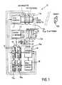
- FIG. 1The block diagram (FIG. 1) of the proposed image processing system and a schematic illustration of the robot system are shown in the two figures of the drawing (FIG. 2).
- the general idea of the inventionis based on the fact that by means of a CCD camera with zoom lens, a laser radar and an evaluation and control system, a greatly simplified pattern recognition is made possible, which is therefore applicable to the greatest extent to all objects involved, including those just manipulated, which creates the possibility the robot system with flexible manipulator arms in a lightweight design and the simplest sensors for position and movement control.
- the flexible manipulatorwith its simple position and movement sensors that measure within large tolerances corresponds to the human arm.
- the two- and three-dimensional sensorscorrespond to the human eyes, and the evaluation and control system corresponds to the human brain.
- the flexible manipulatorsare able to handle workpieces or objects of almost any mass precisely and in a controlled manner, as long as their mechanical stability is capable of doing so.
- load-dependent deformations of the manipulator armare compensated for in that the manipulator and workpiece are precisely controlled and controlled by the sensors.
- the rudimentary sensor system arranged in the flexible manipulator armserves - as with the human arm - only for additional rough information.
- the robot system 5is provided with a 3D sensor system 13a, which records a three-dimensional image of the environment.
- a laser radar LRis used for this purpose, to which a 2D sensor system 11a for two-dimensional information recording is now additionally assigned.
- Both arrangementsform, with a platform 20 and an evaluation and control system 19a which evaluates the information, the image recording and processing system 10.
- This system 10is composed, in detail, of a CCD camera 11 which is provided with a recording lens designed as a zoom lens 12 , a controllable platform 20 with drive units 21 and 22 and image correlators 15, 16 with reference image memories 15a, 16a for 2D or 3D image processing.
- a laser radar LRconsisting of a laser range finder 13 and a deflection unit 14 is arranged on the platform 20.
- the devices of this platform 20 and these themselvesare acted upon by a control unit 18, which aligns the 2D and 3D sensor systems of 11a and 13a with the suspected object 100.
- the information on this first rough alignmentis taken from the program and data unit 19, in which the necessary knowledge of the robot system, ie the approximate position and the properties of all objects involved, the processing task and the state using the simple sensors 7 for position and movement control the manipulator arms 6 are available.
- 3D imagesare much easier to evaluate than 2D images, since the third dimension assigned to the pixels, the distance to the surfaces of the object and thus its spatial extent, are clearly measured quantities.
- the gray value assigned to the pixelsis a variable, that is to say unclear, depending on the lighting, viewing angle, distance and surface condition.
- the boundary lines of the areas of the same gray valuesare usually usually determines the edges of the object in an additional calculation section; the correlation is then carried out only with respect to these edge lines.
- the spatial extenti.e. The size of the object is not taken directly from the 2D image, but can only be derived after the successful correlation.
- the respective objectis therefore first measured according to the invention with the laser radar LR.
- a laser rangefinder 13a system with a semiconductor laser and a range accuracy of the order of magnitude of 1 to 10 mm can advantageously be used.
- the search field of view and the image resolution in azimuth ⁇ and elevation ⁇are adapted to the respective requirements by the program and data unit 19 via the control unit 18 and the deflection unit 14.
- the following correlation calculation between the 3D image and the corresponding 3D reference imagesis comparatively simple and therefore quick according to the above explanations and identifies the measured object and its special position in space.
- the image resolution possible with a laser radaris not sufficient for full identification in many cases. If, for example, the object is a cube with various fine bores on the various surfaces, these bores - and thus the sought-after, unambiguous orientation of the object in space - can only be achieved through a 2D image correlation with the pixel resolution of conventional TV, which is always significantly higher than that of the laser radar image -Identify cameras. In other cases, in which the resolution of the laser radar 13a is sufficient, it can nevertheless be advantageous to identify only a part of the object with the laser radar 13a and to determine its distance and then to proceed to the 2D image correlation.
- the control unit 18aligns the 2D sensor system 11a via the platform 20 to the object 100 selected with the laser radar LR, if necessary, and controls the zoom lens 12 of the CCD camera 11 in accordance with the measured object distance so that it is in focus and the Camera magnification corresponds exactly to the only one or one of a few two-dimensional reference images of the present view (aspect angle of the object) available in the reference memory 15a.
- One reference image per aspect angleis sufficient if the setting range of the zoom lens 12 is large enough to image an object at the correct magnification at all occurring distances.
- This procedureeliminates time-consuming scale transformations due to the known and balanced magnification. Because of the known and balanced object direction, i.e. Object location in the 2D image also significantly reduces the search area over which the correlation calculation must be carried out. At the same time - especially in the case of CCD cameras with few picture elements - the correlation maximum is higher than in the prior art.
- the described embodimentprovides that the 2D sensor system 11a is readjusted in this way via the ⁇ , ⁇ platform 20 and the units 21, 22 is that the viewing direction is such that the object contours optimally match the pixel grid of the CCD camera 11. This further increases the correlation maximum.
- a further increase in the correlation maximumis finally achieved by a clever choice of the reference images.
- the objects manipulated by robot systemsmostly have geometrically simple shapes with often straight and mutually perpendicular edges. It is therefore proposed to take advantage of this property and to select the scale of the reference image so that the object edges optimally match the grid of the reference image memory. In the event that two or more enlargements of the possible views of the reference object must be saved, i.e. if the zoom range is not sufficient, it is further proposed that these magnifications are each in a ratio of 2: 1 to one another, so that the object edges continue to optimally match the grid of the reference image memory.
Landscapes
- Engineering & Computer Science (AREA)
- Robotics (AREA)
- Mechanical Engineering (AREA)
- Manipulator (AREA)
- Length Measuring Devices By Optical Means (AREA)
- Optical Radar Systems And Details Thereof (AREA)
Abstract
Translated fromGermanDescription
Translated fromGermanDie Erfindung bezieht sich auf eine Roboteranlage mit einem oder mehreren beweglichen Manipulatorarmen gemäß dem Gattungsbegriff des Anspruchs 1.The invention relates to a robot system with one or more movable manipulator arms according to the preamble of claim 1.
Beim Stand der Technik sind die Manipulatoren nach Art des Schwermaschinenbaus konzipiert und ausgeführt, d.h. sie haben eine weitgehend hohe Stabilität und Wiederkehr- bzw. Wiederholgenauigkeit, wobei alle Freiheitsgrade der beweglichen Teile, wie Gelenke, Dreh- und Schubelemente usw. durch hochgenaue Sensoren überwacht und gesteuert werden. Dies ist die Voraussetzung für den detailliert vorprogrammierten Bewegungsablauf derartiger Anlagen, die nur weitgehend konstante Situationen beherrschen, was wiederum höchste Standfestigkeit und Erschütterungsfreiheit etc. voraussetzt und daher zu den schweren, im Vergleich zu den bewegten oder bearbeiteten Objekten eigentlich überdimensionierten Geräten mit hohem Platzbedarf führt. Der Arbeitsvorgang dieser bekannten Geräte ist zumeist voll determiniert, d.h. der Bewegungs- und Bearbeitungsablauf ist detailliert vorprogrammiert. Dies setzt eine konstante Ausgangssituation voraus, bei welcher sich alle Objekte zunächst an genau vorgeschriebenen Orten in vorgeschriebener Orientierung befinden müssen. Hierfür werden bei Serienfertigung mehr oder weniger aufwendige Sortier- und Positionierautomaten benutzt.In the prior art, the manipulators are designed and constructed according to the type of heavy machine construction, i.e. they have a high degree of stability and return or repeat accuracy, with all degrees of freedom of the moving parts, such as joints, rotating and pushing elements, etc. being monitored and controlled by highly precise sensors. This is the prerequisite for the detailed preprogrammed sequence of movements of such systems, which can only handle largely constant situations, which in turn presupposes maximum stability and freedom from vibrations etc. and therefore leads to the heavy devices which are actually oversized compared to moving or processed objects and require a lot of space. The working process of these known devices is mostly fully determined, i.e. the movement and processing sequence is pre-programmed in detail. This presupposes a constant starting situation, in which all objects must first be in precisely prescribed locations in the prescribed orientation. For series production, more or less complex sorting and positioning machines are used.
Um diese zumeist mechanisch arbeitenden Geräte einzusparen, wurden Manipulatoren entwickelt, die mittels TV-Bildverarbeitung gesteuert werden. Die Lage und Orientierung der zu manipulierenden Objekte werden mittels einer TV-Kamera bestimmt, die mit fester Brennweite Szene und Objekt aufnimmt und wonach ein Bildkorrelator dann dieses Bild in eine endliche Zahl von Rasterpunkten auflöst und die digitalisierte Szene mit Objekt mit dem Referenzobjekt für verschiedene Vergrößerungen und alle vorkommenden Aspektwinkel desselben korreliert.In order to save these mostly mechanical devices, manipulators have been developed that are controlled by means of TV image processing. The location and Orientation of the objects to be manipulated are determined by means of a TV camera, which records the scene and the object with a fixed focal length and then an image correlator then resolves this image into a finite number of halftone dots and the digitized scene with the object with the reference object for various magnifications and all occurring Aspect angle correlated.
Der konstruktive Aufbau der Anlagen nach dem Stand der Technik ist um ein vielfaches zu hoch und überdimensioniert. Der Funktionsablauf ist ebenfalls zu aufwendig. Die Bildkorrelation erfordert viele Rechenabläufe bis die "beste" Vergrößerung aus der aus Gründen der Rechenökonomie diskreten Menge aller möglicher Vergrößerungen des Referenzobjektes sowie dessen genaue Lage innerhalb des TV-Bildes gefunden ist. Um dieses zu vermeiden, muß die Beobachtungssituation wieder stark eingeschränkt und vorbestimmt werden, indem z.B. das zu erkennende Objekt das Gesichtsfeld der TV-Kamera in definiertem Abstand und in hinreichend definierter Richtung z.B. auf einem Förderband passiert.The structural design of the systems according to the state of the art is many times too high and oversized. The functional sequence is also too complex. The image correlation requires many arithmetic processes until the "best" magnification is found from the set of all possible magnifications of the reference object, as well as its exact position within the TV image, for reasons of computing economy. To avoid this, the observation situation must be severely restricted and predetermined again, e.g. by the object to be recognized the field of view of the TV camera at a defined distance and in a sufficiently defined direction e.g. happened on a conveyor belt.
Weiterhin wird der größtmögliche Spitzenwert der Korrelationsfunktion nur zufällig erreicht, nämlich dann, wenn einmal die beste Vergrößerung, d.h. diejenige beim Korrelationsmaximum zufällig mit der (festen) Kameravergrößerung übereinstimmt und zum andernmal die Entfernung des Objekts zufällig gerade so groß und die Blickrichtung derart ist, daß die Objektkonturen optimal mit dem Bildpunktraster der digitalisierten Szene übereinstimmen. Weiterhin ist erforderlich, daß die Objektentfernung im Tiefenschärfendbereich des Kameraobjektivs liegt.Furthermore, the greatest possible peak value of the correlation function is only reached by chance, namely when the best magnification, i.e. that at the correlation maximum, coincides with the (fixed) camera magnification and, on the other hand, the distance of the object happens to be just as large and the viewing direction is such that the object contours correspond optimally with the pixel grid of the digitized scene. It is also necessary that the object distance is in the depth of field of the camera lens.
Der vorliegenden Erfindung liegt die Aufgabe zugrunde, die Nachteile des aufgezeigten Standes der Technik zu beseitigen und eine Roboteranlage zu schaffen, die mit geringem Rechenaufwand und einer CCD-Kamera mit vergleichsweise wenigen Bildelementen die Mustererkennung durchführen, und die manipulierten Objekte selbst sowie ihre Rückwirkung auf die Manipulatorarme laufend vermessen kann, so daß es ermöglicht wird, auf hochstabile Manipulatoren und hochgenauen Sensoren zur Lage- und Bewegungskontrolle zu verzichten und die Manipulatoren der Roboteranlage flexibel und in Leichtbauweise auszuführen, obwohl derartige Manipulatoren nicht mehr starr sein können, sondern bei Belastung und Bewegung sich verformen, d.h. flexibel sind und damit eine hohe Widerkehrgenauigkeit zunächst nicht mehr möglich ist.The present invention has for its object to eliminate the disadvantages of the prior art shown and to create a robot system that perform the pattern recognition with little computation effort and a CCD camera with comparatively few picture elements, and the manipulated objects themselves and their reaction to them Manipulator arms can be measured continuously, so that it is possible to dispense with highly stable manipulators and high-precision sensors for position and movement control and to carry out the manipulators of the robot system flexibly and in a lightweight design, although such manipulators can no longer be rigid, but during loading and movement deform, ie are flexible and a high return accuracy is initially no longer possible.
Diese Aufgabe wird durch die im Anspruch 1 aufgeführten Maßnahmen gelöst. In den Unteransprüchen sind weitere Ausgestaltungen aufgezeigt und in der nachfolgenden Beschreibung ist ein Ausführungbeispiel erläutert. In den beiden Figuren der Zeichnung sind das Blockschaltbild (Fig.1) der vorgeschlagenen Bildverarbeitungsanlage sowie eine schematische Darstellung der Roboteranlage gezeigt (Fig.2).This object is achieved by the measures listed in claim 1. Further embodiments are shown in the subclaims and an exemplary embodiment is explained in the following description. The block diagram (FIG. 1) of the proposed image processing system and a schematic illustration of the robot system are shown in the two figures of the drawing (FIG. 2).
Der allgemeine Erfindungsgedanke beruht darauf, daß mittels einer CCD-Kamera mit Zoomobjektiv, einem Laserradar und einer Auswerte- und Steueranlage eine stark vereinfachte Mustererkennung ermöglicht wird, die deshalb in weitesten Umfang auf alle beteiligen Objekte einschließlich der gerade manipulierten anwendbar ist, wodurch die Möglichkeit geschaffen wird, die Roboteranlage mit flexiblen Manipulatorarmen in Leichtbauweise und einfachster Sensorik zur Lage- und Bewegungskontrolle auszuführen. Hierbei entspricht in einer Analogie der flexible Manipulator mit seinen einfachen und in großen Toleranzen messenden Lage- und Bewegungssensoren dem menschlichen Arm. Die zwei- und dreidimensionale Sensorik (TV und Laserradar) entspricht hier den menschlichen Augen, und die Auswerte- und Steueranlage entspricht dem menschlichen Gehirn.The general idea of the invention is based on the fact that by means of a CCD camera with zoom lens, a laser radar and an evaluation and control system, a greatly simplified pattern recognition is made possible, which is therefore applicable to the greatest extent to all objects involved, including those just manipulated, which creates the possibility the robot system with flexible manipulator arms in a lightweight design and the simplest sensors for position and movement control. In an analogy, the flexible manipulator with its simple position and movement sensors that measure within large tolerances corresponds to the human arm. The two- and three-dimensional sensors (TV and laser radar) correspond to the human eyes, and the evaluation and control system corresponds to the human brain.
In derselben Analogie ist es den flexiblen Manipulatoren möglich, Werkstücke bzw. Objekte von nahezu beliebiger Masse genau und kontrolliert zu handhaben, solange ihre mechanische Stabilität hierzu überhaupt in der Lage ist. Lastabhängige Deformationen des Manipulatorarmes werden wie beim menschlichen Arm dadurch kompensiert, daß Manipulator und Werkstück von der Sensorik genau kontrolliert und gesteuert werden. Die im flexiblen Manipulatorarm angeordnete rudimentäre Sensorik dient - wie beim menschlichen Arm äquivalent - nur zu einer zusätzlichen Grobinformation.In the same analogy, the flexible manipulators are able to handle workpieces or objects of almost any mass precisely and in a controlled manner, as long as their mechanical stability is capable of doing so. As with the human arm, load-dependent deformations of the manipulator arm are compensated for in that the manipulator and workpiece are precisely controlled and controlled by the sensors. The rudimentary sensor system arranged in the flexible manipulator arm serves - as with the human arm - only for additional rough information.
Die Roboteranlage 5 wird mit einer 3D-Sensorik 13a versehen, die ein dreidimensionales Abbild der Umwelt aufnimmt. Im vorgeschlagenen Ausführungsbeispiel wird hierzu ein Laserradar LR eingesetzt, dem zusätzlich nun noch eine 2D-Sensorik 11a zur zweidimensionalen Informationsaufnahme zugeordnet ist. Beide Anordnungen bilden mit einer Plattform 20 und einer, die Informationen auswertenden Auswerte- und Steueranlage 19a die Bildaufnahme- und -verarbeitungsanlage 10. Diese Anlage 10 setzt sich im einzelnen aus einer CCD-Kamera 11, die mit einer als Zoomobjektiv 12 ausgebildeten Aufnahmeoptik versehen ist, einer steuerbaren Plattform 20 mit Antriebseinheiten 21 und 22 und Bildkorrelatoren 15, 16 mit Referenzbildspeichern 15a, 16a für die 2D- bzw. 3D-Bildverarbeitung zusammen. Weiterhin ist auf der Plattform 20 ein aus einem Laserentfernungsmesser 13 und einer Ablenkeinheit 14 bestehendes Laserradar LR angeordnet. Die Einrichtungen dieser Plattform 20 sowie diese selbst werden von einer Steuereinheit 18 beaufschlagt, die die 2D- und 3D-Sensoriken von 11a und 13a auf das vermutete Objekt 100 ausrichtet. Die Informationen zu dieser ersten Grobausrichtung werden der Programm- und Dateneinheit 19 entnommen, in welcher die notwendigen Kenntnisse der Roboteranlage, d.h. die ungefähre Lage und die Eigenschaften aller beteiligten Objekte, die Bearbeitungsaufgabe sowie mittels der Einfach-Sensorik 7 zur Lage- und Bewegungskontrolle der Zustand der Manipulatorarme 6 verfügbar sind.The
Gegebenenfalls können solche Vorinformationen auch aufgrund einer vorläufigen, stark vereinfachten Aufnahme und Verarbeitung von 2D- bzw. 3D-Bildern gewonnen werden.If necessary, such preliminary information can also be obtained on the basis of a preliminary, greatly simplified recording and processing of 2D or 3D images.
Bekanntermaßen sind 3D-Bilder sehr viel einfacher auszuwerten als 2D-Bilder, da die den Bildpunkten zugeordnete dritte Dimension, die Entfernung zu den Flächen des Objektes und damit dessen räumliche Ausdehnung, eindeutig gemessene Größen sind. Im Gegensatz dazu ist bei einem 2D-Bild der den Bildpunkten zugeordnete Grauwert ein je nach Beleuchtung, Blickwinkel, Entfernung und Oberflächenbeschaffenheit variable, d.h. nicht eindeutige Größe.As is known, 3D images are much easier to evaluate than 2D images, since the third dimension assigned to the pixels, the distance to the surfaces of the object and thus its spatial extent, are clearly measured quantities. In contrast to this, in the case of a 2D image, the gray value assigned to the pixels is a variable, that is to say unclear, depending on the lighting, viewing angle, distance and surface condition.
Vor der eigentlichen Bildkorrelation werden daher zumeist die Begrenzungslinien der Flächen gleicher Grauwerte, d.h. in der Regel die Kanten des Objektes in einem zusätzlichen Rechenabschnitt bestimmt; die Korrelation wird dann nur bezüglich dieser Kantenlinien durchgeführt.Before the actual image correlation, the boundary lines of the areas of the same gray values are usually usually determines the edges of the object in an additional calculation section; the correlation is then carried out only with respect to these edge lines.
Zudem kann die räumliche Ausdehnung, d.h. Größe des Objekts nicht unmittelbar dem 2D-Bild entnommen, sondern erst nach der erfolgreichen Korrelation abgeleitet werden.In addition, the spatial extent, i.e. The size of the object is not taken directly from the 2D image, but can only be derived after the successful correlation.
Der Aufwand zur Mustererkennung mittels Korrelation zwischen Objektbild und einer Datenbank von Referenzbildern des Objektes in den verschiedenen vorkommenden Ansichten ist daher bei 2D-Bildern wesentlich höher als bei 3D-Bildern. So muß beispielsweise bei der 2D-Bildkorrelation die Referenzbildgröße nacheinander einer Reihe von Maßstabstransformationen unterworfen werden, bis die entfernungsabhängige, scheinbare Göße des Objektes derjenigen des Referenzobjektes entspricht, so daß die Korrelationsfunktion ein Maximum ergibt. Bei der aus Gründen der Rechenzeit notwendigerweise nur endlichen Zahl von diskreten Vergrößerungsschnitten wird überdies der größtmögliche Spitzenwert der Korrelationsfunktion nur zufällig erreicht, nämlich dann, wenn
- a) die "beste" Vergrößerung, d.h. diejenige beim Korrelationsmaximum, zufällig der (festen) Kamera-Ver-größerung entspricht, mit welcher das 2D-Bild aufgenommen wurde, und
- b) die Blickrichtung bei der die Bildaufnahme derart ist, daß die Objektkonturen optimal mit dem Bildpunktraster übereinstimmen. Selbstverständlich muß auch die Objektentferung im Tiefenschärfenbereich des Kameraobjektivs liegen.
- a) the "best" magnification, ie that at the correlation maximum, coincidentally corresponds to the (fixed) camera magnification with which the 2D image was taken, and
- b) the direction of view at which the image is recorded in such a way that the object contours correspond optimally with the pixel grid. Of course, the object distance must also be in the depth of field of the camera lens.
Nach der ersten Grobausrichtung der 2D- und 3D-Sensoriken 11a, 13a wird daher erfindungsgemäß das jeweilige Objekt zunächst mit dem Laserradar LR vermessen. Als Laserentfernungsmesser 13 kann hierbei vorteilhaft ein nach dem Phasenmeßverfahren arbeitendes System mit Halbleiterlaser und einer Entfernungsgenauigkeit der Größenordnung 1 bis 10 mm verwendet werden. Das Suchgesichtsfeld sowie die Bildauflösung in Azimuth Θ und Elevation φ wird durch die Programm- und Dateneinheit 19 über die Steuereinheit 18 und die Ablenkeinheit 14 den jeweiligen Erfordernissen angepaßt. Die nachfolgende Korrelationsrechnung zwischen dem 3D-Bild und den entsprechenden 3D-Referenzbildern ist nach den obigen Ausführungen vergleichsweise einfach und daher schnell und identifiziert das vermessene Objekt und seine spezielle Lage im Raum.After the first rough alignment of the 2D and
In der Praxis genügt in vielen Fällen die mit einem Laserradar mögliche Bildauflösung nicht zur vollen Identifizierung. Ist beispielsweise das Objekt ein Würfel mit verschiedenen feinen Bohrungen auf den verschiedenen Flächen, so lassen sich diese Bohrungen - und damit die gesuchte, eindeutige Orientierung des Objekts im Raum - nur durch eine 2D-Bildkorrelation mit der gegenüber dem Laserradarbild immer deutlich höheren Bildpunktauflösung üblicher TV-Kameras identifizieren. In anderen Fällen, in denen die Auflösung des Laserradars 13a ausreichend ist, kann es trotzdem vorteilhaft sein, nur einen Teil des Objektes mit dem Laserradar 13a zu identifizieren und seine Entfernung zu bestimmen und anschließend zur 2D-Bildkorrelation überzugehen.In practice, the image resolution possible with a laser radar is not sufficient for full identification in many cases. If, for example, the object is a cube with various fine bores on the various surfaces, these bores - and thus the sought-after, unambiguous orientation of the object in space - can only be achieved through a 2D image correlation with the pixel resolution of conventional TV, which is always significantly higher than that of the laser radar image -Identify cameras. In other cases, in which the resolution of the laser radar 13a is sufficient, it can nevertheless be advantageous to identify only a part of the object with the laser radar 13a and to determine its distance and then to proceed to the 2D image correlation.
Bei diesem Prozeß richtet die Steuereinheit 18 die 2D-Sensorik 11a über die Plattform 20 auf das mit dem Laserradar LR ausgewählte Objekt 100 gegebenenfalls nach und steuert das Zoomobjektiv 12 der CCD-Kamera 11 gemäß der gemessenen Objektentfernung so, daß es scharf gestellt ist und die Kameravergrößerung exakt dem einzigen bzw. einem von wenigen im Referenzspeicher 15a verfügbaren zweidimensionalen Referenzbildern der vorliegenden Ansicht (Aspektwinkel des Objektes) entspricht. Jeweils ein Referenzbild pro Aspektwinkel genügt dabei dann, wenn der Einstellbereich des Zoomobjektivs 12 genügend groß ist, um ein Objekt bei allen vorkommenden Entfernungen in der richtigen Vergrößerung abzubilden. Bei diesem Vorgehen entfallen also wegen der vorbekannten und abgeglichenen Vergrößerung zeitraubende Maßstabstransformationen. Wegen der vorbekannten und abgeglichenen Objektrichtung, d.h. Objektlage im 2D-Bild reduziert sich ebenso erheblich der Suchbereich, über welchen die Korrelationsrechnung durchgeführt werden muß. Gleichzeitig wird - insbesondere bei CCD-Kameras mit wenigen Bildelementen - das Korrelationsmaximum höher als beim bisherigen Stand der Technik.In this process, the
Weiterhin sieht die beschriebene Ausführungsform vor, daß die 2D-Sensorik 11a über die ϑ, φ-Plattform 20 und die Einheiten 21, 22 derart nachgesteuert wird, daß die Blickrichtung derart ist, daß die Objektkonturen optimal mit dem Bildpunktraster der CCD-Kamera 11 übereinstimmen. Dadurch wird das Korrelationsmaximum weiter erhöht.Furthermore, the described embodiment provides that the
Eine weitere Erhöhung des Korrelationsmaximums wird schließlich noch durch eine geschickte Wahl der Referenzbilder erreicht. Die von Roboteranlagen manipulierten Objekte haben zumeist geometrisch einfache Formen mit oft geraden und aufeinander senkrecht stehenden Kanten. Es wird daher vorgeschlagen, diese Eigenschaft auszunutzen und den Maßstab des Referenzbildes so zu wählen, daß die Objektkanten optimal mit dem Raster des Referenzbildspeichers übereinstimmen. Für den Fall, daß zwei oder mehrere Vergrößerungen der möglichen Ansichten des Referenzobjektes gespeichert werden müssen, d.h. wenn der Zoombereich nicht ausreicht, wird weiterhin vorgeschlagen, daß diese Vergrößerungen jeweils im Verhältnis 2:1 zueinander stehen, so daß die Objektkanten weiterhin optimal mit dem Raster des Referenzbildspeichers übereinstimmen.A further increase in the correlation maximum is finally achieved by a clever choice of the reference images. The objects manipulated by robot systems mostly have geometrically simple shapes with often straight and mutually perpendicular edges. It is therefore proposed to take advantage of this property and to select the scale of the reference image so that the object edges optimally match the grid of the reference image memory. In the event that two or more enlargements of the possible views of the reference object must be saved, i.e. if the zoom range is not sufficient, it is further proposed that these magnifications are each in a ratio of 2: 1 to one another, so that the object edges continue to optimally match the grid of the reference image memory.
Es darf daher festgestellt werden, daß erheblich weniger Bildpunkte ausreichen, um ein mit dem Stand der Technik gleichhohes Korrelationsmaximum und damit eine zuverlässige Mustererkennung zu erreichen, also nur ein relativ grobes Raster für die 2D-Bildaufnahme und die Speicherung erforderlich ist. Dies erlaubt einmal die Verwendung einfacherer Kamerasensoren und gestattet eine noch schnellere Bildverarbeitung.It can therefore be stated that considerably fewer pixels are sufficient to achieve a correlation maximum which is the same as that of the prior art and thus reliable pattern recognition, that is to say only a relatively coarse grid is required for 2D image recording and storage. On the one hand, this allows the use of simpler camera sensors and enables even faster image processing.
Aus dem Blockschaltbild der Zeichnung dürfte leicht verständlich der Zusammenhang und der Funktionsablauf der die Informationen aufnehmenden und auswertenden Bildaufnahme- und -verarbeitungsanlage 10 dargestellt und entnehmbar sein. Hieraus geht nocheinmal hervor, daß Richtung und Gesichtsfeld des Laserradars LR mittels der Plattform 20 und der Ablenkeinheit 14 nach Maßgabe der Programmeinheit 19 und gegebenenfalls einer vorläufigen, stark vereinfachten Bildverarbeitung eingestellt werden, und daß das Zoomobjektiv 12 in Entfernung und Brennweite nach Maßgabe des Laserradars LR und der 3D-Bildkorrelation eingestellt wird. Zur Mustererkennung wird in dem 3D-Bildkorrelator 16 eine Korrelation zwischen dem dreidimensionalen Bild des Laserradars LR und den im 3D-Referenzbildspeicher 16a gespeicherten dreidimensionalen Referenzbildern des Objekts 100 in den verschiedenen vorkommenden Ansichten durchgeführt. Das gleiche geschieht mit dem zweidimensionalen Bild in den Einheiten 15 und 15a. Die Vergrößerung des Zoomobjektivs 12 ist so gewählt, und die Plattform 20 ist nach der 3D-Bildkorrelation derart nachgesteuert, daß die Objektkonturen optimal mit dem Bildpunktraster der CCD-Kamera 11 übereinstimmen.From the block diagram of the drawing it should be easy to understand the connection and the functional sequence of the information receiving and evaluating Image recording and
Erwähnt soll noch werden, daß für sogenannte einfache Roboteranlagen bzw. deren Manipulatoren es möglich ist, daß anstelle des Laserradars nur ein einfacher Laserentfernungsmesser ohne Zuordnung einer Ablenkeinheit und der Einrichtungen 16a, 16b zur 3D-Bildkorrelation vorgesehen werden kann, anstelle der Identifizierung und Lokalisierung eines Objekts durch die 3D-Bildkorrelation wird dann nur eine einfache Entfernungsmessung zu einem Punkt des vermuteten Objekts durchgeführt. Zoomobjektiv und Blickrichtung der CCD-Kamera können dann nur ungefähr eingestellt werden, so daß Korrelationsrechnungen in einem gewissen Bereich von Vergrößerung und Lage der Referenzbilder im Vergleich zum Bild der CCD-Kamera erforderlich werden. Eine derartig vereinfachte Anlage kann in einfachen Anwendungsfällen vorteilhaft sein.It should also be mentioned that for so-called simple robot systems or their manipulators it is possible that instead of the laser radar, only a simple laser rangefinder can be provided without assigning a deflection unit and the
Claims (8)
Translated fromGermanPriority Applications (1)
| Application Number | Priority Date | Filing Date | Title |
|---|---|---|---|
| AT87112607TATE83699T1 (en) | 1986-10-15 | 1987-08-29 | ROBOT SYSTEM WITH MOVING MANIPULATORS. |
Applications Claiming Priority (2)
| Application Number | Priority Date | Filing Date | Title |
|---|---|---|---|
| DE3635076 | 1986-10-15 | ||
| DE19863635076DE3635076A1 (en) | 1986-10-15 | 1986-10-15 | ROBOT SYSTEM WITH MOVABLE MANIPULATORS |
Publications (3)
| Publication Number | Publication Date |
|---|---|
| EP0263952A2true EP0263952A2 (en) | 1988-04-20 |
| EP0263952A3 EP0263952A3 (en) | 1989-10-25 |
| EP0263952B1 EP0263952B1 (en) | 1992-12-23 |
Family
ID=6311767
Family Applications (1)
| Application Number | Title | Priority Date | Filing Date |
|---|---|---|---|
| EP87112607AExpired - LifetimeEP0263952B1 (en) | 1986-10-15 | 1987-08-29 | Robot unit with moving manipulators |
Country Status (3)
| Country | Link |
|---|---|
| EP (1) | EP0263952B1 (en) |
| AT (1) | ATE83699T1 (en) |
| DE (2) | DE3635076A1 (en) |
Cited By (9)
| Publication number | Priority date | Publication date | Assignee | Title |
|---|---|---|---|---|
| FR2681162A1 (en)* | 1991-09-10 | 1993-03-12 | Paris Val De Marne Universite | Process and device for aiding the remote control of robotized vehicles during a remote operating procedure undertaken in a hostile environment |
| US5215423A (en)* | 1990-09-21 | 1993-06-01 | Edelhoff Polytechnik Gmbh & Co. | System for determining the spatial position of an object by means of a video optical sensor |
| EP0812662A4 (en)* | 1995-12-27 | 2000-11-15 | Fanuc Ltd | Composite sensor robot system |
| WO2016083972A1 (en)* | 2014-11-25 | 2016-06-02 | Quartesan Diego | Robotic system comprising a telemetric device with a laser measuring device and a passive video camera |
| CN108839047A (en)* | 2018-03-28 | 2018-11-20 | 江苏求恒医疗器械有限公司 | A kind of Medical instrument fixture with clamp device |
| CN109129474A (en)* | 2018-08-10 | 2019-01-04 | 上海交通大学 | Manipulator active grabbing device and method based on multi-modal fusion |
| CN109702135A (en)* | 2018-12-29 | 2019-05-03 | 上海发那科机器人有限公司 | A method of the device of automatic positioning characteristic area and its adjustment are vertical |
| CN109866210A (en)* | 2019-03-28 | 2019-06-11 | 合肥工业大学 | A kind of easy-to-assemble both arms six-DOF robot |
| GB2589419A (en)* | 2019-08-09 | 2021-06-02 | Quantum Leap Tech Limited | Fabric maintenance sensor system |
Families Citing this family (10)
| Publication number | Priority date | Publication date | Assignee | Title |
|---|---|---|---|---|
| US5946449A (en)* | 1996-04-05 | 1999-08-31 | Georgia Tech Research Corporation | Precision apparatus with non-rigid, imprecise structure, and method for operating same |
| DE19814779A1 (en) | 1998-04-02 | 1999-10-07 | Vitronic Dr Ing Stein Bildvera | Method and device for controlling a movable object |
| DE19907465C2 (en)* | 1999-02-13 | 2002-01-31 | Daimlerchrysler Rail Systems | Device for identifying objects and uses of the device |
| DE10229555A1 (en)* | 2002-07-01 | 2004-01-15 | Volkswagen Ag | Operation of a robotic handling system provides precise position control based upon a 2D camera and a distance sensor to give 3D control |
| DE102007008903A1 (en)* | 2007-02-23 | 2008-08-28 | Abb Technology Ag | Device for controlling a robot |
| DE102009001894B4 (en) | 2009-03-26 | 2018-06-28 | pmdtechnologies ag | Robot system with 3D camera |
| CN104570938B (en)* | 2015-01-06 | 2019-02-12 | 常州先进制造技术研究所 | A control method of a dual-arm robot system in cartridge production |
| DE102015100983A1 (en) | 2015-01-23 | 2016-07-28 | Sick Ag | Method for locating gripping points of objects |
| CN106313118A (en)* | 2016-11-05 | 2017-01-11 | 佛山科学技术学院 | Alignmentinstrument |
| CN110202589B (en)* | 2019-06-14 | 2021-02-05 | 东方电子股份有限公司 | Autonomous navigation robot based on double laser radars in one line |
Family Cites Families (3)
| Publication number | Priority date | Publication date | Assignee | Title |
|---|---|---|---|---|
| DE3031507A1 (en)* | 1980-08-21 | 1982-02-25 | Licentia Patent-Verwaltungs-Gmbh, 6000 Frankfurt | Automatic orientation control of industrial manipulator - has video camera monitoring orientation of component for comparison with required position |
| EP0108549B1 (en)* | 1982-10-29 | 1988-01-07 | Kabushiki Kaisha Toshiba | Control system of multi-joint arm robot apparatus |
| DE3405909A1 (en)* | 1984-02-18 | 1985-08-22 | Licentia Patent-Verwaltungs-Gmbh, 6000 Frankfurt | DEVICE FOR DETECTING, MEASURING ANALYSIS AND / OR REGULATING TECHNICAL PROCEDURES |
- 1986
- 1986-10-15DEDE19863635076patent/DE3635076A1/enactiveGranted
- 1987
- 1987-08-29EPEP87112607Apatent/EP0263952B1/ennot_activeExpired - Lifetime
- 1987-08-29DEDE8787112607Tpatent/DE3783196D1/ennot_activeExpired - Fee Related
- 1987-08-29ATAT87112607Tpatent/ATE83699T1/enactive
Cited By (11)
| Publication number | Priority date | Publication date | Assignee | Title |
|---|---|---|---|---|
| US5215423A (en)* | 1990-09-21 | 1993-06-01 | Edelhoff Polytechnik Gmbh & Co. | System for determining the spatial position of an object by means of a video optical sensor |
| FR2681162A1 (en)* | 1991-09-10 | 1993-03-12 | Paris Val De Marne Universite | Process and device for aiding the remote control of robotized vehicles during a remote operating procedure undertaken in a hostile environment |
| EP0812662A4 (en)* | 1995-12-27 | 2000-11-15 | Fanuc Ltd | Composite sensor robot system |
| WO2016083972A1 (en)* | 2014-11-25 | 2016-06-02 | Quartesan Diego | Robotic system comprising a telemetric device with a laser measuring device and a passive video camera |
| CN108839047A (en)* | 2018-03-28 | 2018-11-20 | 江苏求恒医疗器械有限公司 | A kind of Medical instrument fixture with clamp device |
| CN109129474A (en)* | 2018-08-10 | 2019-01-04 | 上海交通大学 | Manipulator active grabbing device and method based on multi-modal fusion |
| CN109129474B (en)* | 2018-08-10 | 2020-07-14 | 上海交通大学 | Manipulator active grasping device and method based on multimodal fusion |
| CN109702135A (en)* | 2018-12-29 | 2019-05-03 | 上海发那科机器人有限公司 | A method of the device of automatic positioning characteristic area and its adjustment are vertical |
| CN109866210A (en)* | 2019-03-28 | 2019-06-11 | 合肥工业大学 | A kind of easy-to-assemble both arms six-DOF robot |
| CN109866210B (en)* | 2019-03-28 | 2021-12-17 | 合肥工业大学 | Double-arm six-degree-of-freedom robot easy to assemble |
| GB2589419A (en)* | 2019-08-09 | 2021-06-02 | Quantum Leap Tech Limited | Fabric maintenance sensor system |
Also Published As
| Publication number | Publication date |
|---|---|
| DE3635076C2 (en) | 1988-07-28 |
| ATE83699T1 (en) | 1993-01-15 |
| EP0263952B1 (en) | 1992-12-23 |
| DE3783196D1 (en) | 1993-02-04 |
| DE3635076A1 (en) | 1988-04-28 |
| EP0263952A3 (en) | 1989-10-25 |
Similar Documents
| Publication | Publication Date | Title |
|---|---|---|
| EP0263952B1 (en) | Robot unit with moving manipulators | |
| EP3421189B1 (en) | Method for monitoring a machine | |
| DE69428686T2 (en) | IMAGING DEVICE AND METHOD FOR DETERMINING FOCUS INFORMATION | |
| EP2227356B1 (en) | Method and system for extremely precise positioning of at least one object in the end position of a space | |
| EP1681111B1 (en) | Method for operating a manufacturing device | |
| DE69808431T2 (en) | METHOD AND DEVICE FOR GRAPHICALLY IMAGING RADIATION SOURCES | |
| DE3742867A1 (en) | DEVICE FOR JOINTING ELEMENTS IN CORRESPONDING RECEIVING ELEMENTS OF AN OBJECT | |
| DE2739679A1 (en) | PROCESS AND SYSTEM FOR THE THREE-DIMENSIONAL DETERMINATION OF THE SURFACE SHAPE OF A BODY | |
| DE102015011914A1 (en) | Contour line measuring device and robot system | |
| EP2255930A1 (en) | Method and system for extremely precise positioning of at least one object in the end position in space | |
| EP3195256B1 (en) | Method and apparatus for identifying structural elements of a projected structural pattern in camera images | |
| EP2603767B1 (en) | Method for calibrating a measurement system and device for carrying out the method | |
| DE10254435B4 (en) | Method for three-dimensional edge detection with Z height adjustment | |
| DE19525561C2 (en) | 3D measuring device | |
| DE19812609A1 (en) | Method for determining the position and rotational position of an object | |
| EP1143221B1 (en) | Method for determining the position of a coordinate system of an object in a 3D space | |
| DE2259762B2 (en) | Process for the automatic evaluation of stereo images | |
| EP1098268A2 (en) | Method for the threedimensional optical measurement of object surfaces | |
| DE112021005353T5 (en) | Image processing system and image processing method | |
| DE69008409T2 (en) | Seam tracking between mated parts. | |
| DE10159574A1 (en) | Relative movement correction method for robot gripper or machining tool comparing reference images and/or image data with actual images or image data | |
| EP0360880A1 (en) | Method of segmenting three-dimensional scenes | |
| EP0356620A1 (en) | Automatic focusing adjustment of a video camera for industrial or military purposes | |
| DE3446009C2 (en) | ||
| DE102020212279B3 (en) | Device for calibrating a spatial position of a center of an entrance pupil of a camera, calibration method for this, and a system for determining the relative position of centers of entrance pupils of at least two cameras, which are mounted on a common support frame, to one another, and determination methods for this |
Legal Events
| Date | Code | Title | Description |
|---|---|---|---|
| PUAI | Public reference made under article 153(3) epc to a published international application that has entered the european phase | Free format text:ORIGINAL CODE: 0009012 | |
| AK | Designated contracting states | Kind code of ref document:A2 Designated state(s):AT CH DE FR GB IT LI SE | |
| PUAL | Search report despatched | Free format text:ORIGINAL CODE: 0009013 | |
| AK | Designated contracting states | Kind code of ref document:A3 Designated state(s):AT CH DE FR GB IT LI SE | |
| 17P | Request for examination filed | Effective date:19891111 | |
| 17Q | First examination report despatched | Effective date:19901211 | |
| ITTA | It: last paid annual fee | ||
| GRAA | (expected) grant | Free format text:ORIGINAL CODE: 0009210 | |
| ITF | It: translation for a ep patent filed | ||
| RAP1 | Party data changed (applicant data changed or rights of an application transferred) | Owner name:MERCEDES-BENZ AG | |
| AK | Designated contracting states | Kind code of ref document:B1 Designated state(s):AT CH DE FR GB IT LI SE | |
| REF | Corresponds to: | Ref document number:83699 Country of ref document:AT Date of ref document:19930115 Kind code of ref document:T | |
| REF | Corresponds to: | Ref document number:3783196 Country of ref document:DE Date of ref document:19930204 | |
| GBT | Gb: translation of ep patent filed (gb section 77(6)(a)/1977) | Effective date:19930112 | |
| ET | Fr: translation filed | ||
| PLBE | No opposition filed within time limit | Free format text:ORIGINAL CODE: 0009261 | |
| STAA | Information on the status of an ep patent application or granted ep patent | Free format text:STATUS: NO OPPOSITION FILED WITHIN TIME LIMIT | |
| 26N | No opposition filed | ||
| EAL | Se: european patent in force in sweden | Ref document number:87112607.4 | |
| PGFP | Annual fee paid to national office [announced via postgrant information from national office to epo] | Ref country code:GB Payment date:19960809 Year of fee payment:10 | |
| PGFP | Annual fee paid to national office [announced via postgrant information from national office to epo] | Ref country code:FR Payment date:19960814 Year of fee payment:10 | |
| PGFP | Annual fee paid to national office [announced via postgrant information from national office to epo] | Ref country code:AT Payment date:19960820 Year of fee payment:10 | |
| PGFP | Annual fee paid to national office [announced via postgrant information from national office to epo] | Ref country code:SE Payment date:19960822 Year of fee payment:10 | |
| PGFP | Annual fee paid to national office [announced via postgrant information from national office to epo] | Ref country code:CH Payment date:19960823 Year of fee payment:10 | |
| PGFP | Annual fee paid to national office [announced via postgrant information from national office to epo] | Ref country code:DE Payment date:19961015 Year of fee payment:10 | |
| PG25 | Lapsed in a contracting state [announced via postgrant information from national office to epo] | Ref country code:GB Free format text:LAPSE BECAUSE OF NON-PAYMENT OF DUE FEES Effective date:19970829 Ref country code:AT Free format text:LAPSE BECAUSE OF NON-PAYMENT OF DUE FEES Effective date:19970829 | |
| PG25 | Lapsed in a contracting state [announced via postgrant information from national office to epo] | Ref country code:SE Free format text:LAPSE BECAUSE OF NON-PAYMENT OF DUE FEES Effective date:19970830 | |
| PG25 | Lapsed in a contracting state [announced via postgrant information from national office to epo] | Ref country code:LI Free format text:LAPSE BECAUSE OF NON-PAYMENT OF DUE FEES Effective date:19970831 Ref country code:CH Free format text:LAPSE BECAUSE OF NON-PAYMENT OF DUE FEES Effective date:19970831 | |
| REG | Reference to a national code | Ref country code:CH Ref legal event code:PFA Free format text:MERCEDES-BENZ AKTIENGESELLSCHAFT TRANSFER- DAIMLER-BENZ AKTIENGESELLSCHAFT Ref country code:CH Ref legal event code:NV Representative=s name:ISLER & PEDRAZZINI AG | |
| REG | Reference to a national code | Ref country code:FR Ref legal event code:TP | |
| REG | Reference to a national code | Ref country code:GB Ref legal event code:732E | |
| REG | Reference to a national code | Ref country code:CH Ref legal event code:PL | |
| GBPC | Gb: european patent ceased through non-payment of renewal fee | Effective date:19970829 | |
| PG25 | Lapsed in a contracting state [announced via postgrant information from national office to epo] | Ref country code:FR Free format text:LAPSE BECAUSE OF NON-PAYMENT OF DUE FEES Effective date:19980430 | |
| PG25 | Lapsed in a contracting state [announced via postgrant information from national office to epo] | Ref country code:DE Free format text:LAPSE BECAUSE OF NON-PAYMENT OF DUE FEES Effective date:19980501 | |
| EUG | Se: european patent has lapsed | Ref document number:87112607.4 | |
| REG | Reference to a national code | Ref country code:FR Ref legal event code:ST | |
| PG25 | Lapsed in a contracting state [announced via postgrant information from national office to epo] | Ref country code:IT Free format text:LAPSE BECAUSE OF NON-PAYMENT OF DUE FEES;WARNING: LAPSES OF ITALIAN PATENTS WITH EFFECTIVE DATE BEFORE 2007 MAY HAVE OCCURRED AT ANY TIME BEFORE 2007. THE CORRECT EFFECTIVE DATE MAY BE DIFFERENT FROM THE ONE RECORDED. Effective date:20050829 |