EP0257359B1 - Modular hip prosthesis - Google Patents
Modular hip prosthesisDownload PDFInfo
- Publication number
- EP0257359B1 EP0257359B1EP87111180AEP87111180AEP0257359B1EP 0257359 B1EP0257359 B1EP 0257359B1EP 87111180 AEP87111180 AEP 87111180AEP 87111180 AEP87111180 AEP 87111180AEP 0257359 B1EP0257359 B1EP 0257359B1
- Authority
- EP
- European Patent Office
- Prior art keywords
- neck
- stem
- implant system
- body member
- head
- Prior art date
- Legal status (The legal status is an assumption and is not a legal conclusion. Google has not performed a legal analysis and makes no representation as to the accuracy of the status listed.)
- Expired - Lifetime
Links
- 210000000689upper legAnatomy0.000claimsdescription45
- 239000007943implantSubstances0.000claimsdescription20
- 238000006467substitution reactionMethods0.000claims3
- 210000000988bone and boneAnatomy0.000description8
- 239000000463materialSubstances0.000description7
- 238000000034methodMethods0.000description7
- 230000007704transitionEffects0.000description4
- 238000004873anchoringMethods0.000description3
- 238000003780insertionMethods0.000description3
- 230000037431insertionEffects0.000description3
- 238000012986modificationMethods0.000description3
- 230000004048modificationEffects0.000description3
- 239000002639bone cementSubstances0.000description2
- 238000005266castingMethods0.000description2
- 238000000576coating methodMethods0.000description2
- 210000002436femur neckAnatomy0.000description2
- 230000001788irregularEffects0.000description2
- 238000003754machiningMethods0.000description2
- 238000002271resectionMethods0.000description2
- 238000004381surface treatmentMethods0.000description2
- 210000003484anatomyAnatomy0.000description1
- 239000004568cementSubstances0.000description1
- 239000011248coating agentSubstances0.000description1
- 238000013461designMethods0.000description1
- 238000011156evaluationMethods0.000description1
- 239000002184metalSubstances0.000description1
- 230000000399orthopedic effectEffects0.000description1
- 210000001364upper extremityAnatomy0.000description1
Images


Classifications
- A—HUMAN NECESSITIES
- A61—MEDICAL OR VETERINARY SCIENCE; HYGIENE
- A61F—FILTERS IMPLANTABLE INTO BLOOD VESSELS; PROSTHESES; DEVICES PROVIDING PATENCY TO, OR PREVENTING COLLAPSING OF, TUBULAR STRUCTURES OF THE BODY, e.g. STENTS; ORTHOPAEDIC, NURSING OR CONTRACEPTIVE DEVICES; FOMENTATION; TREATMENT OR PROTECTION OF EYES OR EARS; BANDAGES, DRESSINGS OR ABSORBENT PADS; FIRST-AID KITS
- A61F2/00—Filters implantable into blood vessels; Prostheses, i.e. artificial substitutes or replacements for parts of the body; Appliances for connecting them with the body; Devices providing patency to, or preventing collapsing of, tubular structures of the body, e.g. stents
- A61F2/02—Prostheses implantable into the body
- A61F2/30—Joints
- A61F2/32—Joints for the hip
- A61F2/36—Femoral heads ; Femoral endoprostheses
- A—HUMAN NECESSITIES
- A61—MEDICAL OR VETERINARY SCIENCE; HYGIENE
- A61B—DIAGNOSIS; SURGERY; IDENTIFICATION
- A61B90/00—Instruments, implements or accessories specially adapted for surgery or diagnosis and not covered by any of the groups A61B1/00 - A61B50/00, e.g. for luxation treatment or for protecting wound edges
- A61B90/03—Automatic limiting or abutting means, e.g. for safety
- A61B2090/031—Automatic limiting or abutting means, e.g. for safety torque limiting
- A—HUMAN NECESSITIES
- A61—MEDICAL OR VETERINARY SCIENCE; HYGIENE
- A61B—DIAGNOSIS; SURGERY; IDENTIFICATION
- A61B90/00—Instruments, implements or accessories specially adapted for surgery or diagnosis and not covered by any of the groups A61B1/00 - A61B50/00, e.g. for luxation treatment or for protecting wound edges
- A61B90/03—Automatic limiting or abutting means, e.g. for safety
- A61B2090/037—Automatic limiting or abutting means, e.g. for safety with a frangible part, e.g. by reduced diameter
- A—HUMAN NECESSITIES
- A61—MEDICAL OR VETERINARY SCIENCE; HYGIENE
- A61F—FILTERS IMPLANTABLE INTO BLOOD VESSELS; PROSTHESES; DEVICES PROVIDING PATENCY TO, OR PREVENTING COLLAPSING OF, TUBULAR STRUCTURES OF THE BODY, e.g. STENTS; ORTHOPAEDIC, NURSING OR CONTRACEPTIVE DEVICES; FOMENTATION; TREATMENT OR PROTECTION OF EYES OR EARS; BANDAGES, DRESSINGS OR ABSORBENT PADS; FIRST-AID KITS
- A61F2/00—Filters implantable into blood vessels; Prostheses, i.e. artificial substitutes or replacements for parts of the body; Appliances for connecting them with the body; Devices providing patency to, or preventing collapsing of, tubular structures of the body, e.g. stents
- A61F2/02—Prostheses implantable into the body
- A61F2/30—Joints
- A61F2/30721—Accessories
- A61F2/30728—Collars; Bone edge protectors
- A—HUMAN NECESSITIES
- A61—MEDICAL OR VETERINARY SCIENCE; HYGIENE
- A61F—FILTERS IMPLANTABLE INTO BLOOD VESSELS; PROSTHESES; DEVICES PROVIDING PATENCY TO, OR PREVENTING COLLAPSING OF, TUBULAR STRUCTURES OF THE BODY, e.g. STENTS; ORTHOPAEDIC, NURSING OR CONTRACEPTIVE DEVICES; FOMENTATION; TREATMENT OR PROTECTION OF EYES OR EARS; BANDAGES, DRESSINGS OR ABSORBENT PADS; FIRST-AID KITS
- A61F2/00—Filters implantable into blood vessels; Prostheses, i.e. artificial substitutes or replacements for parts of the body; Appliances for connecting them with the body; Devices providing patency to, or preventing collapsing of, tubular structures of the body, e.g. stents
- A61F2/02—Prostheses implantable into the body
- A61F2/30—Joints
- A61F2/30767—Special external or bone-contacting surface, e.g. coating for improving bone ingrowth
- A61F2/30907—Nets or sleeves applied to surface of prostheses or in cement
- A—HUMAN NECESSITIES
- A61—MEDICAL OR VETERINARY SCIENCE; HYGIENE
- A61F—FILTERS IMPLANTABLE INTO BLOOD VESSELS; PROSTHESES; DEVICES PROVIDING PATENCY TO, OR PREVENTING COLLAPSING OF, TUBULAR STRUCTURES OF THE BODY, e.g. STENTS; ORTHOPAEDIC, NURSING OR CONTRACEPTIVE DEVICES; FOMENTATION; TREATMENT OR PROTECTION OF EYES OR EARS; BANDAGES, DRESSINGS OR ABSORBENT PADS; FIRST-AID KITS
- A61F2/00—Filters implantable into blood vessels; Prostheses, i.e. artificial substitutes or replacements for parts of the body; Appliances for connecting them with the body; Devices providing patency to, or preventing collapsing of, tubular structures of the body, e.g. stents
- A61F2/02—Prostheses implantable into the body
- A61F2/30—Joints
- A61F2/32—Joints for the hip
- A61F2/36—Femoral heads ; Femoral endoprostheses
- A61F2/3609—Femoral heads or necks; Connections of endoprosthetic heads or necks to endoprosthetic femoral shafts
- A—HUMAN NECESSITIES
- A61—MEDICAL OR VETERINARY SCIENCE; HYGIENE
- A61F—FILTERS IMPLANTABLE INTO BLOOD VESSELS; PROSTHESES; DEVICES PROVIDING PATENCY TO, OR PREVENTING COLLAPSING OF, TUBULAR STRUCTURES OF THE BODY, e.g. STENTS; ORTHOPAEDIC, NURSING OR CONTRACEPTIVE DEVICES; FOMENTATION; TREATMENT OR PROTECTION OF EYES OR EARS; BANDAGES, DRESSINGS OR ABSORBENT PADS; FIRST-AID KITS
- A61F2/00—Filters implantable into blood vessels; Prostheses, i.e. artificial substitutes or replacements for parts of the body; Appliances for connecting them with the body; Devices providing patency to, or preventing collapsing of, tubular structures of the body, e.g. stents
- A61F2/02—Prostheses implantable into the body
- A61F2/30—Joints
- A61F2/32—Joints for the hip
- A61F2/36—Femoral heads ; Femoral endoprostheses
- A61F2/3662—Femoral shafts
- A61F2/367—Proximal or metaphyseal parts of shafts
- A—HUMAN NECESSITIES
- A61—MEDICAL OR VETERINARY SCIENCE; HYGIENE
- A61F—FILTERS IMPLANTABLE INTO BLOOD VESSELS; PROSTHESES; DEVICES PROVIDING PATENCY TO, OR PREVENTING COLLAPSING OF, TUBULAR STRUCTURES OF THE BODY, e.g. STENTS; ORTHOPAEDIC, NURSING OR CONTRACEPTIVE DEVICES; FOMENTATION; TREATMENT OR PROTECTION OF EYES OR EARS; BANDAGES, DRESSINGS OR ABSORBENT PADS; FIRST-AID KITS
- A61F2/00—Filters implantable into blood vessels; Prostheses, i.e. artificial substitutes or replacements for parts of the body; Appliances for connecting them with the body; Devices providing patency to, or preventing collapsing of, tubular structures of the body, e.g. stents
- A61F2/02—Prostheses implantable into the body
- A61F2/30—Joints
- A61F2/32—Joints for the hip
- A61F2/36—Femoral heads ; Femoral endoprostheses
- A61F2/3662—Femoral shafts
- A61F2/3672—Intermediate parts of shafts
- A—HUMAN NECESSITIES
- A61—MEDICAL OR VETERINARY SCIENCE; HYGIENE
- A61F—FILTERS IMPLANTABLE INTO BLOOD VESSELS; PROSTHESES; DEVICES PROVIDING PATENCY TO, OR PREVENTING COLLAPSING OF, TUBULAR STRUCTURES OF THE BODY, e.g. STENTS; ORTHOPAEDIC, NURSING OR CONTRACEPTIVE DEVICES; FOMENTATION; TREATMENT OR PROTECTION OF EYES OR EARS; BANDAGES, DRESSINGS OR ABSORBENT PADS; FIRST-AID KITS
- A61F2/00—Filters implantable into blood vessels; Prostheses, i.e. artificial substitutes or replacements for parts of the body; Appliances for connecting them with the body; Devices providing patency to, or preventing collapsing of, tubular structures of the body, e.g. stents
- A61F2/02—Prostheses implantable into the body
- A61F2/30—Joints
- A61F2/32—Joints for the hip
- A61F2/36—Femoral heads ; Femoral endoprostheses
- A61F2/3662—Femoral shafts
- A61F2/3676—Distal or diaphyseal parts of shafts
- A—HUMAN NECESSITIES
- A61—MEDICAL OR VETERINARY SCIENCE; HYGIENE
- A61F—FILTERS IMPLANTABLE INTO BLOOD VESSELS; PROSTHESES; DEVICES PROVIDING PATENCY TO, OR PREVENTING COLLAPSING OF, TUBULAR STRUCTURES OF THE BODY, e.g. STENTS; ORTHOPAEDIC, NURSING OR CONTRACEPTIVE DEVICES; FOMENTATION; TREATMENT OR PROTECTION OF EYES OR EARS; BANDAGES, DRESSINGS OR ABSORBENT PADS; FIRST-AID KITS
- A61F2/00—Filters implantable into blood vessels; Prostheses, i.e. artificial substitutes or replacements for parts of the body; Appliances for connecting them with the body; Devices providing patency to, or preventing collapsing of, tubular structures of the body, e.g. stents
- A61F2/02—Prostheses implantable into the body
- A61F2/30—Joints
- A61F2/46—Special tools for implanting artificial joints
- A61F2/4603—Special tools for implanting artificial joints for insertion or extraction of endoprosthetic joints or of accessories thereof
- A61F2/4607—Special tools for implanting artificial joints for insertion or extraction of endoprosthetic joints or of accessories thereof of hip femoral endoprostheses
- A—HUMAN NECESSITIES
- A61—MEDICAL OR VETERINARY SCIENCE; HYGIENE
- A61F—FILTERS IMPLANTABLE INTO BLOOD VESSELS; PROSTHESES; DEVICES PROVIDING PATENCY TO, OR PREVENTING COLLAPSING OF, TUBULAR STRUCTURES OF THE BODY, e.g. STENTS; ORTHOPAEDIC, NURSING OR CONTRACEPTIVE DEVICES; FOMENTATION; TREATMENT OR PROTECTION OF EYES OR EARS; BANDAGES, DRESSINGS OR ABSORBENT PADS; FIRST-AID KITS
- A61F2/00—Filters implantable into blood vessels; Prostheses, i.e. artificial substitutes or replacements for parts of the body; Appliances for connecting them with the body; Devices providing patency to, or preventing collapsing of, tubular structures of the body, e.g. stents
- A61F2/02—Prostheses implantable into the body
- A61F2/30—Joints
- A61F2002/30001—Additional features of subject-matter classified in A61F2/28, A61F2/30 and subgroups thereof
- A61F2002/30108—Shapes
- A61F2002/3011—Cross-sections or two-dimensional shapes
- A61F2002/30112—Rounded shapes, e.g. with rounded corners
- A61F2002/30113—Rounded shapes, e.g. with rounded corners circular
- A—HUMAN NECESSITIES
- A61—MEDICAL OR VETERINARY SCIENCE; HYGIENE
- A61F—FILTERS IMPLANTABLE INTO BLOOD VESSELS; PROSTHESES; DEVICES PROVIDING PATENCY TO, OR PREVENTING COLLAPSING OF, TUBULAR STRUCTURES OF THE BODY, e.g. STENTS; ORTHOPAEDIC, NURSING OR CONTRACEPTIVE DEVICES; FOMENTATION; TREATMENT OR PROTECTION OF EYES OR EARS; BANDAGES, DRESSINGS OR ABSORBENT PADS; FIRST-AID KITS
- A61F2/00—Filters implantable into blood vessels; Prostheses, i.e. artificial substitutes or replacements for parts of the body; Appliances for connecting them with the body; Devices providing patency to, or preventing collapsing of, tubular structures of the body, e.g. stents
- A61F2/02—Prostheses implantable into the body
- A61F2/30—Joints
- A61F2002/30001—Additional features of subject-matter classified in A61F2/28, A61F2/30 and subgroups thereof
- A61F2002/30108—Shapes
- A61F2002/30199—Three-dimensional shapes
- A61F2002/30224—Three-dimensional shapes cylindrical
- A—HUMAN NECESSITIES
- A61—MEDICAL OR VETERINARY SCIENCE; HYGIENE
- A61F—FILTERS IMPLANTABLE INTO BLOOD VESSELS; PROSTHESES; DEVICES PROVIDING PATENCY TO, OR PREVENTING COLLAPSING OF, TUBULAR STRUCTURES OF THE BODY, e.g. STENTS; ORTHOPAEDIC, NURSING OR CONTRACEPTIVE DEVICES; FOMENTATION; TREATMENT OR PROTECTION OF EYES OR EARS; BANDAGES, DRESSINGS OR ABSORBENT PADS; FIRST-AID KITS
- A61F2/00—Filters implantable into blood vessels; Prostheses, i.e. artificial substitutes or replacements for parts of the body; Appliances for connecting them with the body; Devices providing patency to, or preventing collapsing of, tubular structures of the body, e.g. stents
- A61F2/02—Prostheses implantable into the body
- A61F2/30—Joints
- A61F2002/30001—Additional features of subject-matter classified in A61F2/28, A61F2/30 and subgroups thereof
- A61F2002/30316—The prosthesis having different structural features at different locations within the same prosthesis; Connections between prosthetic parts; Special structural features of bone or joint prostheses not otherwise provided for
- A61F2002/30329—Connections or couplings between prosthetic parts, e.g. between modular parts; Connecting elements
- A61F2002/30331—Connections or couplings between prosthetic parts, e.g. between modular parts; Connecting elements made by longitudinally pushing a protrusion into a complementarily-shaped recess, e.g. held by friction fit
- A61F2002/30354—Cylindrically-shaped protrusion and recess, e.g. cylinder of circular basis
- A—HUMAN NECESSITIES
- A61—MEDICAL OR VETERINARY SCIENCE; HYGIENE
- A61F—FILTERS IMPLANTABLE INTO BLOOD VESSELS; PROSTHESES; DEVICES PROVIDING PATENCY TO, OR PREVENTING COLLAPSING OF, TUBULAR STRUCTURES OF THE BODY, e.g. STENTS; ORTHOPAEDIC, NURSING OR CONTRACEPTIVE DEVICES; FOMENTATION; TREATMENT OR PROTECTION OF EYES OR EARS; BANDAGES, DRESSINGS OR ABSORBENT PADS; FIRST-AID KITS
- A61F2/00—Filters implantable into blood vessels; Prostheses, i.e. artificial substitutes or replacements for parts of the body; Appliances for connecting them with the body; Devices providing patency to, or preventing collapsing of, tubular structures of the body, e.g. stents
- A61F2/02—Prostheses implantable into the body
- A61F2/30—Joints
- A61F2002/30001—Additional features of subject-matter classified in A61F2/28, A61F2/30 and subgroups thereof
- A61F2002/30316—The prosthesis having different structural features at different locations within the same prosthesis; Connections between prosthetic parts; Special structural features of bone or joint prostheses not otherwise provided for
- A61F2002/30329—Connections or couplings between prosthetic parts, e.g. between modular parts; Connecting elements
- A61F2002/30331—Connections or couplings between prosthetic parts, e.g. between modular parts; Connecting elements made by longitudinally pushing a protrusion into a complementarily-shaped recess, e.g. held by friction fit
- A61F2002/30362—Connections or couplings between prosthetic parts, e.g. between modular parts; Connecting elements made by longitudinally pushing a protrusion into a complementarily-shaped recess, e.g. held by friction fit with possibility of relative movement between the protrusion and the recess
- A61F2002/30364—Rotation about the common longitudinal axis
- A61F2002/30367—Rotation about the common longitudinal axis with additional means for preventing said rotation
- A—HUMAN NECESSITIES
- A61—MEDICAL OR VETERINARY SCIENCE; HYGIENE
- A61F—FILTERS IMPLANTABLE INTO BLOOD VESSELS; PROSTHESES; DEVICES PROVIDING PATENCY TO, OR PREVENTING COLLAPSING OF, TUBULAR STRUCTURES OF THE BODY, e.g. STENTS; ORTHOPAEDIC, NURSING OR CONTRACEPTIVE DEVICES; FOMENTATION; TREATMENT OR PROTECTION OF EYES OR EARS; BANDAGES, DRESSINGS OR ABSORBENT PADS; FIRST-AID KITS
- A61F2/00—Filters implantable into blood vessels; Prostheses, i.e. artificial substitutes or replacements for parts of the body; Appliances for connecting them with the body; Devices providing patency to, or preventing collapsing of, tubular structures of the body, e.g. stents
- A61F2/02—Prostheses implantable into the body
- A61F2/30—Joints
- A61F2002/30001—Additional features of subject-matter classified in A61F2/28, A61F2/30 and subgroups thereof
- A61F2002/30316—The prosthesis having different structural features at different locations within the same prosthesis; Connections between prosthetic parts; Special structural features of bone or joint prostheses not otherwise provided for
- A61F2002/30329—Connections or couplings between prosthetic parts, e.g. between modular parts; Connecting elements
- A61F2002/30331—Connections or couplings between prosthetic parts, e.g. between modular parts; Connecting elements made by longitudinally pushing a protrusion into a complementarily-shaped recess, e.g. held by friction fit
- A61F2002/30362—Connections or couplings between prosthetic parts, e.g. between modular parts; Connecting elements made by longitudinally pushing a protrusion into a complementarily-shaped recess, e.g. held by friction fit with possibility of relative movement between the protrusion and the recess
- A61F2002/3037—Translation along the common longitudinal axis, e.g. piston
- A61F2002/30373—Translation along the common longitudinal axis, e.g. piston with additional means for preventing said translation
- A—HUMAN NECESSITIES
- A61—MEDICAL OR VETERINARY SCIENCE; HYGIENE
- A61F—FILTERS IMPLANTABLE INTO BLOOD VESSELS; PROSTHESES; DEVICES PROVIDING PATENCY TO, OR PREVENTING COLLAPSING OF, TUBULAR STRUCTURES OF THE BODY, e.g. STENTS; ORTHOPAEDIC, NURSING OR CONTRACEPTIVE DEVICES; FOMENTATION; TREATMENT OR PROTECTION OF EYES OR EARS; BANDAGES, DRESSINGS OR ABSORBENT PADS; FIRST-AID KITS
- A61F2/00—Filters implantable into blood vessels; Prostheses, i.e. artificial substitutes or replacements for parts of the body; Appliances for connecting them with the body; Devices providing patency to, or preventing collapsing of, tubular structures of the body, e.g. stents
- A61F2/02—Prostheses implantable into the body
- A61F2/30—Joints
- A61F2002/30001—Additional features of subject-matter classified in A61F2/28, A61F2/30 and subgroups thereof
- A61F2002/30316—The prosthesis having different structural features at different locations within the same prosthesis; Connections between prosthetic parts; Special structural features of bone or joint prostheses not otherwise provided for
- A61F2002/30329—Connections or couplings between prosthetic parts, e.g. between modular parts; Connecting elements
- A61F2002/30383—Connections or couplings between prosthetic parts, e.g. between modular parts; Connecting elements made by laterally inserting a protrusion, e.g. a rib into a complementarily-shaped groove
- A61F2002/30387—Dovetail connection
- A—HUMAN NECESSITIES
- A61—MEDICAL OR VETERINARY SCIENCE; HYGIENE
- A61F—FILTERS IMPLANTABLE INTO BLOOD VESSELS; PROSTHESES; DEVICES PROVIDING PATENCY TO, OR PREVENTING COLLAPSING OF, TUBULAR STRUCTURES OF THE BODY, e.g. STENTS; ORTHOPAEDIC, NURSING OR CONTRACEPTIVE DEVICES; FOMENTATION; TREATMENT OR PROTECTION OF EYES OR EARS; BANDAGES, DRESSINGS OR ABSORBENT PADS; FIRST-AID KITS
- A61F2/00—Filters implantable into blood vessels; Prostheses, i.e. artificial substitutes or replacements for parts of the body; Appliances for connecting them with the body; Devices providing patency to, or preventing collapsing of, tubular structures of the body, e.g. stents
- A61F2/02—Prostheses implantable into the body
- A61F2/30—Joints
- A61F2002/30001—Additional features of subject-matter classified in A61F2/28, A61F2/30 and subgroups thereof
- A61F2002/30316—The prosthesis having different structural features at different locations within the same prosthesis; Connections between prosthetic parts; Special structural features of bone or joint prostheses not otherwise provided for
- A61F2002/30329—Connections or couplings between prosthetic parts, e.g. between modular parts; Connecting elements
- A61F2002/30405—Connections or couplings between prosthetic parts, e.g. between modular parts; Connecting elements made by screwing complementary threads machined on the parts themselves
- A—HUMAN NECESSITIES
- A61—MEDICAL OR VETERINARY SCIENCE; HYGIENE
- A61F—FILTERS IMPLANTABLE INTO BLOOD VESSELS; PROSTHESES; DEVICES PROVIDING PATENCY TO, OR PREVENTING COLLAPSING OF, TUBULAR STRUCTURES OF THE BODY, e.g. STENTS; ORTHOPAEDIC, NURSING OR CONTRACEPTIVE DEVICES; FOMENTATION; TREATMENT OR PROTECTION OF EYES OR EARS; BANDAGES, DRESSINGS OR ABSORBENT PADS; FIRST-AID KITS
- A61F2/00—Filters implantable into blood vessels; Prostheses, i.e. artificial substitutes or replacements for parts of the body; Appliances for connecting them with the body; Devices providing patency to, or preventing collapsing of, tubular structures of the body, e.g. stents
- A61F2/02—Prostheses implantable into the body
- A61F2/30—Joints
- A61F2002/30001—Additional features of subject-matter classified in A61F2/28, A61F2/30 and subgroups thereof
- A61F2002/30316—The prosthesis having different structural features at different locations within the same prosthesis; Connections between prosthetic parts; Special structural features of bone or joint prostheses not otherwise provided for
- A61F2002/30329—Connections or couplings between prosthetic parts, e.g. between modular parts; Connecting elements
- A61F2002/30433—Connections or couplings between prosthetic parts, e.g. between modular parts; Connecting elements using additional screws, bolts, dowels, rivets or washers e.g. connecting screws
- A—HUMAN NECESSITIES
- A61—MEDICAL OR VETERINARY SCIENCE; HYGIENE
- A61F—FILTERS IMPLANTABLE INTO BLOOD VESSELS; PROSTHESES; DEVICES PROVIDING PATENCY TO, OR PREVENTING COLLAPSING OF, TUBULAR STRUCTURES OF THE BODY, e.g. STENTS; ORTHOPAEDIC, NURSING OR CONTRACEPTIVE DEVICES; FOMENTATION; TREATMENT OR PROTECTION OF EYES OR EARS; BANDAGES, DRESSINGS OR ABSORBENT PADS; FIRST-AID KITS
- A61F2/00—Filters implantable into blood vessels; Prostheses, i.e. artificial substitutes or replacements for parts of the body; Appliances for connecting them with the body; Devices providing patency to, or preventing collapsing of, tubular structures of the body, e.g. stents
- A61F2/02—Prostheses implantable into the body
- A61F2/30—Joints
- A61F2002/30001—Additional features of subject-matter classified in A61F2/28, A61F2/30 and subgroups thereof
- A61F2002/30316—The prosthesis having different structural features at different locations within the same prosthesis; Connections between prosthetic parts; Special structural features of bone or joint prostheses not otherwise provided for
- A61F2002/30329—Connections or couplings between prosthetic parts, e.g. between modular parts; Connecting elements
- A61F2002/30476—Connections or couplings between prosthetic parts, e.g. between modular parts; Connecting elements locked by an additional locking mechanism
- A61F2002/30481—Connections or couplings between prosthetic parts, e.g. between modular parts; Connecting elements locked by an additional locking mechanism using a locking clip
- A—HUMAN NECESSITIES
- A61—MEDICAL OR VETERINARY SCIENCE; HYGIENE
- A61F—FILTERS IMPLANTABLE INTO BLOOD VESSELS; PROSTHESES; DEVICES PROVIDING PATENCY TO, OR PREVENTING COLLAPSING OF, TUBULAR STRUCTURES OF THE BODY, e.g. STENTS; ORTHOPAEDIC, NURSING OR CONTRACEPTIVE DEVICES; FOMENTATION; TREATMENT OR PROTECTION OF EYES OR EARS; BANDAGES, DRESSINGS OR ABSORBENT PADS; FIRST-AID KITS
- A61F2/00—Filters implantable into blood vessels; Prostheses, i.e. artificial substitutes or replacements for parts of the body; Appliances for connecting them with the body; Devices providing patency to, or preventing collapsing of, tubular structures of the body, e.g. stents
- A61F2/02—Prostheses implantable into the body
- A61F2/30—Joints
- A61F2002/30001—Additional features of subject-matter classified in A61F2/28, A61F2/30 and subgroups thereof
- A61F2002/30316—The prosthesis having different structural features at different locations within the same prosthesis; Connections between prosthetic parts; Special structural features of bone or joint prostheses not otherwise provided for
- A61F2002/30329—Connections or couplings between prosthetic parts, e.g. between modular parts; Connecting elements
- A61F2002/30476—Connections or couplings between prosthetic parts, e.g. between modular parts; Connecting elements locked by an additional locking mechanism
- A61F2002/30495—Connections or couplings between prosthetic parts, e.g. between modular parts; Connecting elements locked by an additional locking mechanism using a locking ring
- A—HUMAN NECESSITIES
- A61—MEDICAL OR VETERINARY SCIENCE; HYGIENE
- A61F—FILTERS IMPLANTABLE INTO BLOOD VESSELS; PROSTHESES; DEVICES PROVIDING PATENCY TO, OR PREVENTING COLLAPSING OF, TUBULAR STRUCTURES OF THE BODY, e.g. STENTS; ORTHOPAEDIC, NURSING OR CONTRACEPTIVE DEVICES; FOMENTATION; TREATMENT OR PROTECTION OF EYES OR EARS; BANDAGES, DRESSINGS OR ABSORBENT PADS; FIRST-AID KITS
- A61F2/00—Filters implantable into blood vessels; Prostheses, i.e. artificial substitutes or replacements for parts of the body; Appliances for connecting them with the body; Devices providing patency to, or preventing collapsing of, tubular structures of the body, e.g. stents
- A61F2/02—Prostheses implantable into the body
- A61F2/30—Joints
- A61F2002/30001—Additional features of subject-matter classified in A61F2/28, A61F2/30 and subgroups thereof
- A61F2002/30316—The prosthesis having different structural features at different locations within the same prosthesis; Connections between prosthetic parts; Special structural features of bone or joint prostheses not otherwise provided for
- A61F2002/30329—Connections or couplings between prosthetic parts, e.g. between modular parts; Connecting elements
- A61F2002/30476—Connections or couplings between prosthetic parts, e.g. between modular parts; Connecting elements locked by an additional locking mechanism
- A61F2002/30507—Connections or couplings between prosthetic parts, e.g. between modular parts; Connecting elements locked by an additional locking mechanism using a threaded locking member, e.g. a locking screw or a set screw
- A—HUMAN NECESSITIES
- A61—MEDICAL OR VETERINARY SCIENCE; HYGIENE
- A61F—FILTERS IMPLANTABLE INTO BLOOD VESSELS; PROSTHESES; DEVICES PROVIDING PATENCY TO, OR PREVENTING COLLAPSING OF, TUBULAR STRUCTURES OF THE BODY, e.g. STENTS; ORTHOPAEDIC, NURSING OR CONTRACEPTIVE DEVICES; FOMENTATION; TREATMENT OR PROTECTION OF EYES OR EARS; BANDAGES, DRESSINGS OR ABSORBENT PADS; FIRST-AID KITS
- A61F2/00—Filters implantable into blood vessels; Prostheses, i.e. artificial substitutes or replacements for parts of the body; Appliances for connecting them with the body; Devices providing patency to, or preventing collapsing of, tubular structures of the body, e.g. stents
- A61F2/02—Prostheses implantable into the body
- A61F2/30—Joints
- A61F2002/30001—Additional features of subject-matter classified in A61F2/28, A61F2/30 and subgroups thereof
- A61F2002/30316—The prosthesis having different structural features at different locations within the same prosthesis; Connections between prosthetic parts; Special structural features of bone or joint prostheses not otherwise provided for
- A61F2002/30535—Special structural features of bone or joint prostheses not otherwise provided for
- A61F2002/30604—Special structural features of bone or joint prostheses not otherwise provided for modular
- A61F2002/30616—Sets comprising a plurality of prosthetic parts of different sizes or orientations
- A—HUMAN NECESSITIES
- A61—MEDICAL OR VETERINARY SCIENCE; HYGIENE
- A61F—FILTERS IMPLANTABLE INTO BLOOD VESSELS; PROSTHESES; DEVICES PROVIDING PATENCY TO, OR PREVENTING COLLAPSING OF, TUBULAR STRUCTURES OF THE BODY, e.g. STENTS; ORTHOPAEDIC, NURSING OR CONTRACEPTIVE DEVICES; FOMENTATION; TREATMENT OR PROTECTION OF EYES OR EARS; BANDAGES, DRESSINGS OR ABSORBENT PADS; FIRST-AID KITS
- A61F2/00—Filters implantable into blood vessels; Prostheses, i.e. artificial substitutes or replacements for parts of the body; Appliances for connecting them with the body; Devices providing patency to, or preventing collapsing of, tubular structures of the body, e.g. stents
- A61F2/02—Prostheses implantable into the body
- A61F2/30—Joints
- A61F2/30721—Accessories
- A61F2/30728—Collars; Bone edge protectors
- A61F2002/30729—Separate collars
- A—HUMAN NECESSITIES
- A61—MEDICAL OR VETERINARY SCIENCE; HYGIENE
- A61F—FILTERS IMPLANTABLE INTO BLOOD VESSELS; PROSTHESES; DEVICES PROVIDING PATENCY TO, OR PREVENTING COLLAPSING OF, TUBULAR STRUCTURES OF THE BODY, e.g. STENTS; ORTHOPAEDIC, NURSING OR CONTRACEPTIVE DEVICES; FOMENTATION; TREATMENT OR PROTECTION OF EYES OR EARS; BANDAGES, DRESSINGS OR ABSORBENT PADS; FIRST-AID KITS
- A61F2/00—Filters implantable into blood vessels; Prostheses, i.e. artificial substitutes or replacements for parts of the body; Appliances for connecting them with the body; Devices providing patency to, or preventing collapsing of, tubular structures of the body, e.g. stents
- A61F2/02—Prostheses implantable into the body
- A61F2/30—Joints
- A61F2/30767—Special external or bone-contacting surface, e.g. coating for improving bone ingrowth
- A61F2/30771—Special external or bone-contacting surface, e.g. coating for improving bone ingrowth applied in original prostheses, e.g. holes or grooves
- A61F2002/30772—Apertures or holes, e.g. of circular cross section
- A61F2002/3079—Stepped or enlarged apertures, e.g. having discrete diameter changes
- A—HUMAN NECESSITIES
- A61—MEDICAL OR VETERINARY SCIENCE; HYGIENE
- A61F—FILTERS IMPLANTABLE INTO BLOOD VESSELS; PROSTHESES; DEVICES PROVIDING PATENCY TO, OR PREVENTING COLLAPSING OF, TUBULAR STRUCTURES OF THE BODY, e.g. STENTS; ORTHOPAEDIC, NURSING OR CONTRACEPTIVE DEVICES; FOMENTATION; TREATMENT OR PROTECTION OF EYES OR EARS; BANDAGES, DRESSINGS OR ABSORBENT PADS; FIRST-AID KITS
- A61F2/00—Filters implantable into blood vessels; Prostheses, i.e. artificial substitutes or replacements for parts of the body; Appliances for connecting them with the body; Devices providing patency to, or preventing collapsing of, tubular structures of the body, e.g. stents
- A61F2/02—Prostheses implantable into the body
- A61F2/30—Joints
- A61F2/30767—Special external or bone-contacting surface, e.g. coating for improving bone ingrowth
- A61F2002/30906—Special external or bone-contacting surface, e.g. coating for improving bone ingrowth shot- sand- or grit-blasted
- A—HUMAN NECESSITIES
- A61—MEDICAL OR VETERINARY SCIENCE; HYGIENE
- A61F—FILTERS IMPLANTABLE INTO BLOOD VESSELS; PROSTHESES; DEVICES PROVIDING PATENCY TO, OR PREVENTING COLLAPSING OF, TUBULAR STRUCTURES OF THE BODY, e.g. STENTS; ORTHOPAEDIC, NURSING OR CONTRACEPTIVE DEVICES; FOMENTATION; TREATMENT OR PROTECTION OF EYES OR EARS; BANDAGES, DRESSINGS OR ABSORBENT PADS; FIRST-AID KITS
- A61F2/00—Filters implantable into blood vessels; Prostheses, i.e. artificial substitutes or replacements for parts of the body; Appliances for connecting them with the body; Devices providing patency to, or preventing collapsing of, tubular structures of the body, e.g. stents
- A61F2/02—Prostheses implantable into the body
- A61F2/30—Joints
- A61F2/32—Joints for the hip
- A61F2/36—Femoral heads ; Femoral endoprostheses
- A61F2/3609—Femoral heads or necks; Connections of endoprosthetic heads or necks to endoprosthetic femoral shafts
- A61F2002/3625—Necks
- A—HUMAN NECESSITIES
- A61—MEDICAL OR VETERINARY SCIENCE; HYGIENE
- A61F—FILTERS IMPLANTABLE INTO BLOOD VESSELS; PROSTHESES; DEVICES PROVIDING PATENCY TO, OR PREVENTING COLLAPSING OF, TUBULAR STRUCTURES OF THE BODY, e.g. STENTS; ORTHOPAEDIC, NURSING OR CONTRACEPTIVE DEVICES; FOMENTATION; TREATMENT OR PROTECTION OF EYES OR EARS; BANDAGES, DRESSINGS OR ABSORBENT PADS; FIRST-AID KITS
- A61F2/00—Filters implantable into blood vessels; Prostheses, i.e. artificial substitutes or replacements for parts of the body; Appliances for connecting them with the body; Devices providing patency to, or preventing collapsing of, tubular structures of the body, e.g. stents
- A61F2/02—Prostheses implantable into the body
- A61F2/30—Joints
- A61F2/32—Joints for the hip
- A61F2/36—Femoral heads ; Femoral endoprostheses
- A61F2/3609—Femoral heads or necks; Connections of endoprosthetic heads or necks to endoprosthetic femoral shafts
- A61F2002/365—Connections of heads to necks
- A—HUMAN NECESSITIES
- A61—MEDICAL OR VETERINARY SCIENCE; HYGIENE
- A61F—FILTERS IMPLANTABLE INTO BLOOD VESSELS; PROSTHESES; DEVICES PROVIDING PATENCY TO, OR PREVENTING COLLAPSING OF, TUBULAR STRUCTURES OF THE BODY, e.g. STENTS; ORTHOPAEDIC, NURSING OR CONTRACEPTIVE DEVICES; FOMENTATION; TREATMENT OR PROTECTION OF EYES OR EARS; BANDAGES, DRESSINGS OR ABSORBENT PADS; FIRST-AID KITS
- A61F2/00—Filters implantable into blood vessels; Prostheses, i.e. artificial substitutes or replacements for parts of the body; Appliances for connecting them with the body; Devices providing patency to, or preventing collapsing of, tubular structures of the body, e.g. stents
- A61F2/02—Prostheses implantable into the body
- A61F2/30—Joints
- A61F2/32—Joints for the hip
- A61F2/36—Femoral heads ; Femoral endoprostheses
- A61F2/3609—Femoral heads or necks; Connections of endoprosthetic heads or necks to endoprosthetic femoral shafts
- A61F2002/3652—Connections of necks to shafts
- A—HUMAN NECESSITIES
- A61—MEDICAL OR VETERINARY SCIENCE; HYGIENE
- A61F—FILTERS IMPLANTABLE INTO BLOOD VESSELS; PROSTHESES; DEVICES PROVIDING PATENCY TO, OR PREVENTING COLLAPSING OF, TUBULAR STRUCTURES OF THE BODY, e.g. STENTS; ORTHOPAEDIC, NURSING OR CONTRACEPTIVE DEVICES; FOMENTATION; TREATMENT OR PROTECTION OF EYES OR EARS; BANDAGES, DRESSINGS OR ABSORBENT PADS; FIRST-AID KITS
- A61F2/00—Filters implantable into blood vessels; Prostheses, i.e. artificial substitutes or replacements for parts of the body; Appliances for connecting them with the body; Devices providing patency to, or preventing collapsing of, tubular structures of the body, e.g. stents
- A61F2/02—Prostheses implantable into the body
- A61F2/30—Joints
- A61F2/32—Joints for the hip
- A61F2/36—Femoral heads ; Femoral endoprostheses
- A61F2/3662—Femoral shafts
- A61F2/3672—Intermediate parts of shafts
- A61F2002/3674—Connections of proximal parts to distal parts
- A—HUMAN NECESSITIES
- A61—MEDICAL OR VETERINARY SCIENCE; HYGIENE
- A61F—FILTERS IMPLANTABLE INTO BLOOD VESSELS; PROSTHESES; DEVICES PROVIDING PATENCY TO, OR PREVENTING COLLAPSING OF, TUBULAR STRUCTURES OF THE BODY, e.g. STENTS; ORTHOPAEDIC, NURSING OR CONTRACEPTIVE DEVICES; FOMENTATION; TREATMENT OR PROTECTION OF EYES OR EARS; BANDAGES, DRESSINGS OR ABSORBENT PADS; FIRST-AID KITS
- A61F2/00—Filters implantable into blood vessels; Prostheses, i.e. artificial substitutes or replacements for parts of the body; Appliances for connecting them with the body; Devices providing patency to, or preventing collapsing of, tubular structures of the body, e.g. stents
- A61F2/02—Prostheses implantable into the body
- A61F2/30—Joints
- A61F2/32—Joints for the hip
- A61F2/36—Femoral heads ; Femoral endoprostheses
- A61F2/3662—Femoral shafts
- A61F2002/3678—Geometrical features
- A61F2002/3686—Geometrical features bent
- A—HUMAN NECESSITIES
- A61—MEDICAL OR VETERINARY SCIENCE; HYGIENE
- A61F—FILTERS IMPLANTABLE INTO BLOOD VESSELS; PROSTHESES; DEVICES PROVIDING PATENCY TO, OR PREVENTING COLLAPSING OF, TUBULAR STRUCTURES OF THE BODY, e.g. STENTS; ORTHOPAEDIC, NURSING OR CONTRACEPTIVE DEVICES; FOMENTATION; TREATMENT OR PROTECTION OF EYES OR EARS; BANDAGES, DRESSINGS OR ABSORBENT PADS; FIRST-AID KITS
- A61F2220/00—Fixations or connections for prostheses classified in groups A61F2/00 - A61F2/26 or A61F2/82 or A61F9/00 or A61F11/00 or subgroups thereof
- A61F2220/0025—Connections or couplings between prosthetic parts, e.g. between modular parts; Connecting elements
- A61F2220/0033—Connections or couplings between prosthetic parts, e.g. between modular parts; Connecting elements made by longitudinally pushing a protrusion into a complementary-shaped recess, e.g. held by friction fit
- A—HUMAN NECESSITIES
- A61—MEDICAL OR VETERINARY SCIENCE; HYGIENE
- A61F—FILTERS IMPLANTABLE INTO BLOOD VESSELS; PROSTHESES; DEVICES PROVIDING PATENCY TO, OR PREVENTING COLLAPSING OF, TUBULAR STRUCTURES OF THE BODY, e.g. STENTS; ORTHOPAEDIC, NURSING OR CONTRACEPTIVE DEVICES; FOMENTATION; TREATMENT OR PROTECTION OF EYES OR EARS; BANDAGES, DRESSINGS OR ABSORBENT PADS; FIRST-AID KITS
- A61F2220/00—Fixations or connections for prostheses classified in groups A61F2/00 - A61F2/26 or A61F2/82 or A61F9/00 or A61F11/00 or subgroups thereof
- A61F2220/0025—Connections or couplings between prosthetic parts, e.g. between modular parts; Connecting elements
- A61F2220/0041—Connections or couplings between prosthetic parts, e.g. between modular parts; Connecting elements using additional screws, bolts, dowels or rivets, e.g. connecting screws
- A—HUMAN NECESSITIES
- A61—MEDICAL OR VETERINARY SCIENCE; HYGIENE
- A61F—FILTERS IMPLANTABLE INTO BLOOD VESSELS; PROSTHESES; DEVICES PROVIDING PATENCY TO, OR PREVENTING COLLAPSING OF, TUBULAR STRUCTURES OF THE BODY, e.g. STENTS; ORTHOPAEDIC, NURSING OR CONTRACEPTIVE DEVICES; FOMENTATION; TREATMENT OR PROTECTION OF EYES OR EARS; BANDAGES, DRESSINGS OR ABSORBENT PADS; FIRST-AID KITS
- A61F2230/00—Geometry of prostheses classified in groups A61F2/00 - A61F2/26 or A61F2/82 or A61F9/00 or A61F11/00 or subgroups thereof
- A61F2230/0002—Two-dimensional shapes, e.g. cross-sections
- A61F2230/0004—Rounded shapes, e.g. with rounded corners
- A61F2230/0006—Rounded shapes, e.g. with rounded corners circular
- A—HUMAN NECESSITIES
- A61—MEDICAL OR VETERINARY SCIENCE; HYGIENE
- A61F—FILTERS IMPLANTABLE INTO BLOOD VESSELS; PROSTHESES; DEVICES PROVIDING PATENCY TO, OR PREVENTING COLLAPSING OF, TUBULAR STRUCTURES OF THE BODY, e.g. STENTS; ORTHOPAEDIC, NURSING OR CONTRACEPTIVE DEVICES; FOMENTATION; TREATMENT OR PROTECTION OF EYES OR EARS; BANDAGES, DRESSINGS OR ABSORBENT PADS; FIRST-AID KITS
- A61F2230/00—Geometry of prostheses classified in groups A61F2/00 - A61F2/26 or A61F2/82 or A61F9/00 or A61F11/00 or subgroups thereof
- A61F2230/0063—Three-dimensional shapes
- A61F2230/0069—Three-dimensional shapes cylindrical
- A—HUMAN NECESSITIES
- A61—MEDICAL OR VETERINARY SCIENCE; HYGIENE
- A61F—FILTERS IMPLANTABLE INTO BLOOD VESSELS; PROSTHESES; DEVICES PROVIDING PATENCY TO, OR PREVENTING COLLAPSING OF, TUBULAR STRUCTURES OF THE BODY, e.g. STENTS; ORTHOPAEDIC, NURSING OR CONTRACEPTIVE DEVICES; FOMENTATION; TREATMENT OR PROTECTION OF EYES OR EARS; BANDAGES, DRESSINGS OR ABSORBENT PADS; FIRST-AID KITS
- A61F2310/00—Prostheses classified in A61F2/28 or A61F2/30 - A61F2/44 being constructed from or coated with a particular material
- A61F2310/00389—The prosthesis being coated or covered with a particular material
- A61F2310/00395—Coating or prosthesis-covering structure made of metals or of alloys
Definitions
- the present inventionrelates to an implant system for replacing a portion of a femur, said femur having a neck with a base defining neck basal plane and having a longitudinal cavity defining a first axis
- the implant systemcomprising a plurality of components including a body member formed to include a longitudinal bore that is generally aligned with said first axis and an upwardly and inwardly directed portion, an elongated stem member having an upper portion received in the longitudinal bore being secured therein by a fastener and a lower portion received in the longitudinal cavity of the femur, the upwardly and inwardly directed portion being provided with a head member sized to replace the head of the femur, the implant system.
- the conventional prosthesisgenerally includes a stem portion that is designed to extend downwardly into a cavity within the femur.
- the stem portionmay be secured within the femur by the use of bone cement, or in other adaptions, the stem may be configured to promote bone ingrowth to secure the stem.
- the conventional hip prosthesisalso includes a neck portion that is integral with the stem portion.
- the neck portionis configured to replace the neck of the femur which will normally be resected with the head of the femur. Integrally fixed to the neck portion will normally be a generally spherical head portion that is configured to replace the head of the femur.
- a collarmay be provided between the neck portion and the stem portion to stabilize the prosthesis on the resected femur. Generally, the collar will rest upon the resected surface of the femur to disperse the load on the prosthesis over a greater area, and to compress the underlying bone.
- a collarmay be provided between the neck portion and the stem portion to stabilize the prosthesis and function as a stop or reference point on the resected femur.
- One problem with the conventional, unitary prosthesisis that the hospital has to maintain a large number of differently sized prostheses to accommodate different sizes of bones to be replaced. Generally, a supply of prostheses with and without a collar also must be maintained in the inventory. Also, prostheses with different shapes and angles of the stem and neck portion must be maintained. Even with this large inventory of prostheses, it is often difficult to find a prosthesis that is sized and shaped exactly for the individual patient.
- Patent 4 051 559discloses a prosthesis that includes a separate threaded stem portion that is adapted to be screwed into a prepared cavity within the femur.
- the prosthesisseparately comprises a head portion that includes a neck and collar that is adapted to be mated with the stem portion.
- This prosthesisis not designed to be assembled prior to insertion within the patient.
- the stem portionmust first be screwed into the cavity within the femur.
- the head portionis the attached to the installed stem portion by a bolt.
- the collaris designed to rest upon the resected surface of the femur to support the load placed on the prosthesis.
- the head portionmust include the collar in order to support the weight that will be placed on the prosthesis.
- This prosthesisis limited in flexivility because the stem portion must be straight in order to be screwed into the femur.
- the head portion, including the neck and collaris a unitary structure which further reduces the flexibility of the device.
- Patent 3 806 957discloses a prosthesis that includes a separate stem portion having a proximal end that is broadened somewhat. The broadened proximal end of the stem is configured to receive a head and threaded neck portion to form a complete prosthesis.
- the patentdiscloses that the neck may be elongated or shortened depending on the specific anatomy of different patients.
- This prosthesislike the prosthesis disclosed in patent 4 051 559, is limited in flexibility because the head and neck portion is a unitary structure, and because the head and neck portion attaches directly into the stem portion.
- Patent 3 987 499discloses a prosthesis having a stem or shank component that includes two parts, an anchoring part and a transition part.
- a ballis connected to the transition part.
- a collarmay be included between the ball and a portion of the femur.
- the anchoring partis provided with external threads that are adapted to tap themselves into the femur.
- the transition partis coupled to the anchoring part by a guide pin and securing screw.
- the ballis adapted to be screwed onto the free end of the transition part.
- prosthesisis designed to be placed in position within the body component by component, and assembled sequentially.
- neckis a part of the transistion part, which reduces the flexibility of the device.
- collaris configured to be supported only between the bone and the ball, and is thus subject to rotational and toggling instability.
- This implant systemcomprises a plurality of components including a body member, a head member and a stem.
- the stemis designed as a thread cutter which has to be inserted into a longitudinal cavity of the femur.
- the stemends with a threaded portion within a longitudinal bore of the body member which body member is provided with a recess so that a nut may be threaded on the stem to fix the body member.
- the body memberhas an extension extending upwardly and inwardly to which extension a head member in the form of a ball is fixed.
- the object of the present inventionis to provide an implant system for replacing a portion of a femur which has a greater deal of flexibility in its assembly, both as to the size and the shape of the assembled prosthesis, and which may be assembled in the operating room before any component is inserted into the patient.
- each componentbeing provided in various sizes and shapes and by the upwardly and inwardly directed portion of the body member including a planar surface formed to include an opening and defining a plane generally coincident with said neck basal plane, the head member including means for engaging said head member with the opening in the upwardly and inwardly directed portion of the body member, and a surface at the upper most end of the body member, perpendicular to said first axis, and intersecting the surface, an upper end of the upper portion of the stem member amerging through said surface, said fastener being situated above said surface and having a lower surface confronting the surface.
- One advantage of this implant systemis that with different sizes and shapes of stem members, body members and head members, the number of combinations available to assemble a hip prosthesis is greatly increased without increasing the number of inventoried components so that the flexibility of assembling a hip prosthesis for an individual patient is greatly increased.
- a hip prosthesis of a desired size and shapemay be assembled from the system at the time of the operation.
- the present inventionthus provides the ability to assemble a custom prosthesis by selecting different sizes and shapes of individual components to meet the requirements of the individual patient exactly.
- the respective body member that is inserted over the stem memberis configured to bear a portion of the load that is exerted on the prosthesis.
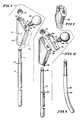
- Fig. 1shows a modular hip prosthesis 10 of the present invention inserted into a femur 12 in which the head and neck portions (not shown) have been resected.
- the resection of the head and neck portions of the femur 12has been performed to leave a generally planar surface 14 on the femur 12.
- a cavity 16has been formed in the femur 12 to receive the prosthesis 10. It will be understood that the resection procedure and the procedure for forming the cavity are well known in the art. It will also be understood that the cavity 16 may be formed to be the exact same size as the prosthesis 10, or if necessary, the cavity 16 may be formed to be somewhat larger than the size of the prosthesis 10.
- the cavity 16 shown in Fig. 1is illustrative of the latter, with the cavity 16 being somewhat larger than the size of the prosthesis 10.
- the prosthesis 10includes an elongated stem member 20 that is generally circular in cross section and includes a lower portion 22 and an upper portion 24.
- the upper portion 24has a diameter slightly less than the diameter of the lower portion 22.
- the demarcation between the upper portion 24 and the lower 22is marked by a chamfer 26.
- the upper extremity of the stem member 20terminates in a threaded end 28.
- the lower portion 22may have any of several surface treatments, including, but not limited to, blasted, smooth, porous bony-ingrowth, and coated.
- a body member 30is shown disposed over the upper portion 24 of the stem member 20, with the upper portion 24 extending through a bore 32 in the body member 30,
- the body member 30includes an upwardly and inwardly (medially) facing surface 34 in which a threaded bore 36 has been formed.
- the surface 34defines a plane 35 that is generally coincident with a plane defined by the base of the neck (not shown) that has been resected from the femur.
- the body member 30may be formed by casting or machining and may have any of the several outer finishes discussed in connection with lower portion 22 of the stem member 20. It will be appreciated that, in the orthopedic implant art, having parts which can be made using machining techniques rather than casting techniques provides significant advantages.
- a neck member 40 which replaces the natural neck of the femur (not shown)extends upwardly and inwardly from the surface 34.
- the neck member 40includes a threaded projection 42 that engages the threaded bore 36 in the body member 30.
- a head member 44is formed on the proximal end of the neck member 40, with the head member 44 replacing the natural head of the femur (not shown).
- Notches 46are formed in the surface of the neck member to permit a wrench (not shown) to be used to tighten the neck member 40 into the body member 30.
- the prosthesis 10is assembled by first inserting the upper portion 24 of the stem member 20 through the bore 32 in the body member 30. A nut 50 is then engaged with the threaded end 28 of the stem member 20 to secure the stem member 20 to the body member 30. It will be understood that the distal end of the bore 32 in the body member 30 includes a chamfer to mate with the chamfer 26 on the stem member 20 to provide a secure engagement.
- the neck member 40is then installed in the body member by engaging the threaded projection 42 with the threaded bore 36. The neck member 40 is then tightened using a wrench (not shown) in the notches 46.
- a grouting material 52or bone cement material, is first injected into the cavity 16.
- the prosthesis 10is then placed in the cavity 16 such that the distal end of the body member 30 rests upon the surface 14, and the lower portion 22 of a stem member 20 extends downwardly into the cavity 16.
- the grouting material 52surrounds the lower portion 22 of the stem 20 and in some cases a portion of the body member 30 and acts in a known manner to secure the prosthesis 10 within the femur 12.
- Fig. 2shows another embodiment of the present invention that is configured to fulfill slightly different anatomical requirements that may be indicated during the replacement procedure.
- This embodimentis configured to replace a portion of the femur 12 in which only the head and neck portions (not shown) have been resected.
- the Calcar portion 54 of the femur 12has been left intact. Therefore, a smaller body member 55 is shown that can be disposed totally within the cavity 16 in the femur 12.
- a collar 56is provided that mates with the body member 55 and extends over the Calcar portion 54 of the femur 12. The collar 56 is provided to distribute the load between the body member 55 and the Calcar portion 54.
- the body member 55includes a key 58 that is received in a keyway 60 that is formed in the stem 20.
- the key 58 and keyway 60cooperate to prevent any rotation of the body member 55 with respect to the stem member 20.
- the prosthesis 10 shown in Fig. 2is inserted into the cavity 16 of the femur 12 that has been filled with a grouting material 52 to secure the prosthesis 10 in a known manner.
- Fig. 2ashows a modification of the embodiment shown in Fig. 2.
- the collar 56 of Fig. 2is replaced by a collar 62 that extends over the threaded end 28 of the stem member 20.
- a chamfered hole 66is formed in the extension of the collar 62 that receives the threaded end 28 of the stem member 20.
- a nut 64 with a chamfer 68is provided to engage the threaded end 28 of the stem member 20 with the chamfer 68 of the nut engaging the chamfered hole 66 of the collar 62.
- the chamfer 68, 66cooperate to securely engage the collar 62 between the body member 55 and the nut 64.
- Fig. 3shows another embodiment of the present invention including a slightly modified stem member 70 that engages the body member 55 of the embodiment shown in Fig. 2.
- the stem member 70includes a shorter upper portion 71 in comparison to the stem member 20, A chamfer 72 is provided between the upper portion 71 and the main portion of the stem member 70.
- the body member 55includes a modified bore 74 extending therethrough to receive the stem member 70.
- the modified bore 74has a chamfer 73 to mate with the chamfer 72 on the stem member 70.
- This modified stem member 70 and body member 55may be used when additional strength in the stem member 70 is required, such as, for example, when the stem member 70 has a diameter smaller than normal.
- FIG 3also shows an extension 76 (shown only in dotted) that may be added to the body member 55 to make the body member 55 similar to the body member 30 shown in Fig. 1.
- the extension 76will be required if the Calcar portion 54 (Fig. 2) of the femur 12 is being resected and replaced.
- Fig. 4shows another embodiment of the present invention similar to the embodiment shown in Figs. 2 and 2a.
- the key 58 on the body portion 55 and the keyway 60 on the stem member 20are located on the opposite side compared to the embodiment shown in Fig. 2.
- the collar 78is similar to the collar 62 shown in Fig. 2a, however the hole 80 in the extension does not contain a chamfer, thereby permitting the use of the unchamfered nut 50 to engage the threaded end 28 of the stem member 20.
- Fig. 5shows another embodiment of the present invention in which a body member 82 is formed in a somewhat irregular shape.
- the irregular shaped body 82may be preferable for insertion into certain femurs (not shown).
- the body member 82may be a cast material, or may be machined in a known manner and may have a surface treatment similar to that described in relation to the body member 30 (Fig. 1).
- Fig. 6shows another embodiment of the present invention having a modified stem member 84.
- the stem member 84includes a curved lower portion 85 that may be inserted into the cavity 16 in the femur 12 (not shown) when the anatomical indications so dictate. It will be understood that the stem member 84 may be mated with either the body member 30, the body member 55, or the body member 82, as discussed previously.
- Fig. 7shows yet another embodiment of the present invention.
- a stem member 86is provided that includes a lower portion 88 that is coated with a bone-ingrowth porous metal coating. Bone-ingrowth coatings are known in the art, and it will be understood that this type of stem 86 is adapted to be inserted into a bone without the use of any grouting or cement material.
- the upper end of the stem 86includes a groove 90 that is adapted to mate with a stem clip 94 after the stem member 86 has been inserted through a bore 93 in the body member 92. It will be understood that the groove 90 and the stem clip 94 function in a manner similar to the threaded end 28 and nuts 50, 64 shown in Figs.
- the body member 92includes a generally upwardly and inwardly (medially) facing surface 96 that is formed to include a generally trapezoid-shaped slot 98.
- a collar 100is provided that includes a generally trapezoidal-shaped projection 110 that is configured to dovetail into the slot 98 to align and position the collar 100 in the body member 92.
- the collar 100includes a hole 112 formed therethrough that aligns with a threaded hole 114 in the body member 92 when the collar 100 is mated with the body member 92.
- Fig. 7also shows a modified neck member 118 that includes a threaded end 120 and a tapered end 122.
- the neck member 118is secured to the body member 92 by passing the threaded end 120 through the hole 112 in the collar 100 and into the threaded hole 114.
- a separate head member 124is shown that is formed to include a tapered hole (not shown) that mates with the tapered end 122 of the neck member 118 to secure the head member 124 to the neck member 118. It will be understood that the neck member 118 and the head member 124 can be of various shapes and sizes other than those illustrated in Fig. 7.
- a collar clip 126is shown that inserts under the projection 110 of the collar 100 to lock the neck member 118 in position after it has been screwed into the threaded hole 114 in the body member 92.
- Fig. 7ashows an adapter block 130 that may be inserted into the slot 98 if the collar 100 (Fig. 7) is not used.
- the adaptor block 130is sized to fill the slot 98 so that the surface 96 on the body member 92 will be generally planar.
- the adaptor block 130 shown in Fig. 7ais configured to accept the stem clip 126 as described above.
- Fig. 7bshows another adapter block 132 that also may be inserted into the slot 98 if the collar 100 (Fig. 7) is not used.
- the adapter block 132is sized to fill the slot 98 so that the surface 96 on the body member 92 will be generally planar.
- the adapter block 132differs from the adapter block 130 in that block 132 is used when no stem clip 126 will be utilized.
- Fig. 7cshows a modified neck member 140 that is similar to the neck member 118 shown in Fig. 7.
- Neck member 140differs in that the threaded end 120 (Fig. 7) is replaced by a tapered end 142 that may be inserted into a tapered hole (not shown) in any of the body members, such as body member 92 (Fig. 7).
- Fig. 8shows the prosthesis of Fig. 7 assembled and in a use position.
- the stem member 86is first inserted through the bore 93 in the body member 92.
- the stem clip 94is then engaged with the groove 90 to secure the stem member 86 within the body member 92.
- the collar 100is then engaged with the body member 92 by sliding the projection 110 into the slot 98 so that the hole 112 aligns with the threaded hole 114.
- the neck member 118is then threadingly engaged into the threaded hole 114 by the threaded end 120.
- the collar clip 126is inserted under the projection 110 to lock the neck member 118 in position.
- the head member 124is then inserted over the tapered end 122 of the neck member 118 to secure the head member 124 to the neck member 118.
- the assembled prosthesisis then inserted into the cavity 16 of the femur 12 so that the collar 100 extends over the Calcar portion 54. It will be understood that in this embodiment the cavity 16 is excavated only to the extent necessary to permit the assembled prosthesis to exactly fit within the cavity 16.
- the lower portion 88 of the stem member 86will be secured within the femur 12 by the natural growth process of the bone into the porous surface.
- the body member 92may also be coated with a bone-ingrowth material to enhance this ingrowth process.
- a prosthesismay be assembled utilizing combinations of the illustrated components. This ability to select different sizes and shapes of components to assemble a prosthesis greatly enhances the flexibility available at the time of the operation. Thus, depending upon the anatomical indications presented by the patient, numerous combinations are available to assemble a prosthesis at the time of the operation to meet the exact requirements for that patient.
Landscapes
- Health & Medical Sciences (AREA)
- Orthopedic Medicine & Surgery (AREA)
- Cardiology (AREA)
- Oral & Maxillofacial Surgery (AREA)
- Transplantation (AREA)
- Engineering & Computer Science (AREA)
- Biomedical Technology (AREA)
- Heart & Thoracic Surgery (AREA)
- Vascular Medicine (AREA)
- Life Sciences & Earth Sciences (AREA)
- Animal Behavior & Ethology (AREA)
- General Health & Medical Sciences (AREA)
- Public Health (AREA)
- Veterinary Medicine (AREA)
- Prostheses (AREA)
Description
- The present invention relates to an implant system for replacing a portion of a femur, said femur having a neck with a base defining neck basal plane and having a longitudinal cavity defining a first axis, the implant system comprising a plurality of components including a body member formed to include a longitudinal bore that is generally aligned with said first axis and an upwardly and inwardly directed portion, an elongated stem member having an upper portion received in the longitudinal bore being secured therein by a fastener and a lower portion received in the longitudinal cavity of the femur, the upwardly and inwardly directed portion being provided with a head member sized to replace the head of the femur, the implant system.
- Conventional prostheses for the replacement of the upper portion of the femur are generally unitary structures. The conventional prosthesis generally includes a stem portion that is designed to extend downwardly into a cavity within the femur. The stem portion may be secured within the femur by the use of bone cement, or in other adaptions, the stem may be configured to promote bone ingrowth to secure the stem. The conventional hip prosthesis also includes a neck portion that is integral with the stem portion. The neck portion is configured to replace the neck of the femur which will normally be resected with the head of the femur. Integrally fixed to the neck portion will normally be a generally spherical head portion that is configured to replace the head of the femur. A collar may be provided between the neck portion and the stem portion to stabilize the prosthesis on the resected femur. Generally, the collar will rest upon the resected surface of the femur to disperse the load on the prosthesis over a greater area, and to compress the underlying bone. A collar may be provided between the neck portion and the stem portion to stabilize the prosthesis and function as a stop or reference point on the resected femur.
- Because conventional prostheses are generally unitary devices, the practice has been to maintain a large inventory of prostheses of different sizes to accomodate the different bone sizes that are to be replaced. Generally, the patient is evaluated by x-ray or some other means to determine the approximate bone size, and consequently the approximate required prosthesis size. During the replacement operation, several different prostheses are made available as suggested by the evaluation. The appropriate prosthesis is then selected for insertion into the patient at the time of operation.
- One problem with the conventional, unitary prosthesis is that the hospital has to maintain a large number of differently sized prostheses to accommodate different sizes of bones to be replaced. Generally, a supply of prostheses with and without a collar also must be maintained in the inventory. Also, prostheses with different shapes and angles of the stem and neck portion must be maintained. Even with this large inventory of prostheses, it is often difficult to find a prosthesis that is sized and shaped exactly for the individual patient.
- Prostheses having a stem portion and a separate head portion are known. One such prosthesis is shown in US-patent 4 051 559. Patent 4 051 559 discloses a prosthesis that includes a separate threaded stem portion that is adapted to be screwed into a prepared cavity within the femur. The prosthesis separately comprises a head portion that includes a neck and collar that is adapted to be mated with the stem portion. This prosthesis is not designed to be assembled prior to insertion within the patient. The stem portion must first be screwed into the cavity within the femur. The head portion is the attached to the installed stem portion by a bolt. The collar is designed to rest upon the resected surface of the femur to support the load placed on the prosthesis. Because of the design of the stem portion, the head portion must include the collar in order to support the weight that will be placed on the prosthesis. This prosthesis is limited in flexivility because the stem portion must be straight in order to be screwed into the femur. Also, the head portion, including the neck and collar is a unitary structure which further reduces the flexibility of the device.
- Another prosthesis having a stem portion and a separate head portion is shown in US-patent 3 806 957. Patent 3 806 957 discloses a prosthesis that includes a separate stem portion having a proximal end that is broadened somewhat. The broadened proximal end of the stem is configured to receive a head and threaded neck portion to form a complete prosthesis. The patent discloses that the neck may be elongated or shortened depending on the specific anatomy of different patients. This prosthesis, like the prosthesis disclosed in patent 4 051 559, is limited in flexibility because the head and neck portion is a unitary structure, and because the head and neck portion attaches directly into the stem portion.
- A prosthesis in which the stem portion comprises more than one component is shown in US-patent 3 987 499. Patent 3 987 499 discloses a prosthesis having a stem or shank component that includes two parts, an anchoring part and a transition part. A ball is connected to the transition part. Also, a collar may be included between the ball and a portion of the femur. The anchoring part is provided with external threads that are adapted to tap themselves into the femur. The transition part is coupled to the anchoring part by a guide pin and securing screw. The ball is adapted to be screwed onto the free end of the transition part. One problem with the prosthesis disclosed in patent 3 987 499 is that the prosthesis is designed to be placed in position within the body component by component, and assembled sequentially. Another problem with this prosthesis is that the neck is a part of the transistion part, which reduces the flexibility of the device. In addition, the collar is configured to be supported only between the bone and the ball, and is thus subject to rotational and toggling instability.
- An implant system for replacing a portion of femur is shown in FR-A 2 225 141. This implant system comprises a plurality of components including a body member, a head member and a stem. The stem is designed as a thread cutter which has to be inserted into a longitudinal cavity of the femur. The stem ends with a threaded portion within a longitudinal bore of the body member which body member is provided with a recess so that a nut may be threaded on the stem to fix the body member. The body member has an extension extending upwardly and inwardly to which extension a head member in the form of a ball is fixed.
- The object of the present invention is to provide an implant system for replacing a portion of a femur which has a greater deal of flexibility in its assembly, both as to the size and the shape of the assembled prosthesis, and which may be assembled in the operating room before any component is inserted into the patient.
- This object is achieved by each component being provided in various sizes and shapes and by the upwardly and inwardly directed portion of the body member including a planar surface formed to include an opening and defining a plane generally coincident with said neck basal plane, the head member including means for engaging said head member with the opening in the upwardly and inwardly directed portion of the body member, and a surface at the upper most end of the body member, perpendicular to said first axis, and intersecting the surface, an upper end of the upper portion of the stem member amerging through said surface, said fastener being situated above said surface and having a lower surface confronting the surface.
- One advantage of this implant system is that with different sizes and shapes of stem members, body members and head members, the number of combinations available to assemble a hip prosthesis is greatly increased without increasing the number of inventoried components so that the flexibility of assembling a hip prosthesis for an individual patient is greatly increased. A hip prosthesis of a desired size and shape may be assembled from the system at the time of the operation. The present invention thus provides the ability to assemble a custom prosthesis by selecting different sizes and shapes of individual components to meet the requirements of the individual patient exactly. The respective body member that is inserted over the stem member is configured to bear a portion of the load that is exerted on the prosthesis.
- Additional objects, features, and advantages of the invention will be apparent to those skilled in the art upon consideration of the following detailed description of preferred embodiments exemplifying the best mode of carrying out the invention as presently perceived.
- The detailed description particularly refers to the accompanying figures in which:
- Fig. 1 is a cross sectional view through one embodiment of the implant system of the present invention installed in a femur;
- Fig. 2 is a view similar to Fig. 1 showing another embodiment of the present invention;
- Fig. 2a is a partial view of a modification of the collar component and nut arrangement of the embodiment shown in Fig. 2;
- Fig. 3 is an exploded perspective view of another embodiment of the present invention showing a modified stem member and body member;
- Fig. 4 is a view similar to Fig. 3 showing another embodiment of the present invention with a collar component and an interlocking key and keyway in the body member and stem member;
- Fig. 5 is a perspective view of another embodiment of the present invention showing a modified body member;
- Fig. 6 is a perspective view of another embodiment of the present invention showing a modified stem member;
- Fig. 7 is an exploded perspective view of another embodiment of the present invention showing a modified stem member and a modified neck and body member;
- Fig. 7a is a perspective view of an adapter block for use when the collar component shown in Fig. 7 is not utilized;
- Fig. 7b is a view similar to Fig. 7A showing a modified adapter block;
- Fig. 7c is a perspective view of a modification of the neck member shown in Fig. 7; and
- Fig. 8 is a cross sectional view through the assembly illustrated in Fig. 7 installed in the femur.
- Referring now to Fig. 1, Fig. 1 shows a
modular hip prosthesis 10 of the present invention inserted into afemur 12 in which the head and neck portions (not shown) have been resected. The resection of the head and neck portions of thefemur 12 has been performed to leave a generallyplanar surface 14 on thefemur 12. Acavity 16 has been formed in thefemur 12 to receive theprosthesis 10. It will be understood that the resection procedure and the procedure for forming the cavity are well known in the art. It will also be understood that thecavity 16 may be formed to be the exact same size as theprosthesis 10, or if necessary, thecavity 16 may be formed to be somewhat larger than the size of theprosthesis 10. Thecavity 16 shown in Fig. 1 is illustrative of the latter, with thecavity 16 being somewhat larger than the size of theprosthesis 10. - The
prosthesis 10 includes anelongated stem member 20 that is generally circular in cross section and includes alower portion 22 and anupper portion 24. Theupper portion 24 has a diameter slightly less than the diameter of thelower portion 22. The demarcation between theupper portion 24 and the lower 22 is marked by achamfer 26. The upper extremity of thestem member 20 terminates in a threadedend 28. Thelower portion 22 may have any of several surface treatments, including, but not limited to, blasted, smooth, porous bony-ingrowth, and coated. - A
body member 30 is shown disposed over theupper portion 24 of thestem member 20, with theupper portion 24 extending through abore 32 in thebody member 30, Thebody member 30 includes an upwardly and inwardly (medially) facingsurface 34 in which a threadedbore 36 has been formed. Thesurface 34 defines aplane 35 that is generally coincident with a plane defined by the base of the neck (not shown) that has been resected from the femur. Thebody member 30 may be formed by casting or machining and may have any of the several outer finishes discussed in connection withlower portion 22 of thestem member 20. It will be appreciated that, in the orthopedic implant art, having parts which can be made using machining techniques rather than casting techniques provides significant advantages. - A
neck member 40 which replaces the natural neck of the femur (not shown) extends upwardly and inwardly from thesurface 34. Theneck member 40 includes a threadedprojection 42 that engages the threaded bore 36 in thebody member 30. Ahead member 44 is formed on the proximal end of theneck member 40, with thehead member 44 replacing the natural head of the femur (not shown).Notches 46 are formed in the surface of the neck member to permit a wrench (not shown) to be used to tighten theneck member 40 into thebody member 30. - The
prosthesis 10 is assembled by first inserting theupper portion 24 of thestem member 20 through thebore 32 in thebody member 30. Anut 50 is then engaged with the threadedend 28 of thestem member 20 to secure thestem member 20 to thebody member 30. It will be understood that the distal end of thebore 32 in thebody member 30 includes a chamfer to mate with thechamfer 26 on thestem member 20 to provide a secure engagement. Theneck member 40 is then installed in the body member by engaging the threadedprojection 42 with the threaded bore 36. Theneck member 40 is then tightened using a wrench (not shown) in thenotches 46. - To install the assembled
prosthesis 10 in thefemur 12, agrouting material 52, or bone cement material, is first injected into thecavity 16. Theprosthesis 10 is then placed in thecavity 16 such that the distal end of thebody member 30 rests upon thesurface 14, and thelower portion 22 of astem member 20 extends downwardly into thecavity 16. Thegrouting material 52 surrounds thelower portion 22 of thestem 20 and in some cases a portion of thebody member 30 and acts in a known manner to secure theprosthesis 10 within thefemur 12. - Fig. 2 shows another embodiment of the present invention that is configured to fulfill slightly different anatomical requirements that may be indicated during the replacement procedure. This embodiment is configured to replace a portion of the
femur 12 in which only the head and neck portions (not shown) have been resected. TheCalcar portion 54 of thefemur 12 has been left intact. Therefore, asmaller body member 55 is shown that can be disposed totally within thecavity 16 in thefemur 12. Also, acollar 56 is provided that mates with thebody member 55 and extends over theCalcar portion 54 of thefemur 12. Thecollar 56 is provided to distribute the load between thebody member 55 and theCalcar portion 54. In this embodiment, thebody member 55 includes a key 58 that is received in akeyway 60 that is formed in thestem 20. The key 58 andkeyway 60 cooperate to prevent any rotation of thebody member 55 with respect to thestem member 20. Theprosthesis 10 shown in Fig. 2 is inserted into thecavity 16 of thefemur 12 that has been filled with agrouting material 52 to secure theprosthesis 10 in a known manner. - Fig. 2a shows a modification of the embodiment shown in Fig. 2. Specifically, the
collar 56 of Fig. 2 is replaced by acollar 62 that extends over the threadedend 28 of thestem member 20. A chamferedhole 66 is formed in the extension of thecollar 62 that receives the threadedend 28 of thestem member 20. Anut 64 with achamfer 68 is provided to engage the threadedend 28 of thestem member 20 with thechamfer 68 of the nut engaging the chamferedhole 66 of thecollar 62. Thechamfer collar 62 between thebody member 55 and thenut 64. - Fig. 3 shows another embodiment of the present invention including a slightly modified
stem member 70 that engages thebody member 55 of the embodiment shown in Fig. 2. Specifically, thestem member 70 includes a shorterupper portion 71 in comparison to thestem member 20, Achamfer 72 is provided between theupper portion 71 and the main portion of thestem member 70. Thebody member 55 includes a modifiedbore 74 extending therethrough to receive thestem member 70. The modified bore 74 has achamfer 73 to mate with thechamfer 72 on thestem member 70. This modifiedstem member 70 andbody member 55 may be used when additional strength in thestem member 70 is required, such as, for example, when thestem member 70 has a diameter smaller than normal. Fig. 3 also shows an extension 76 (shown only in dotted) that may be added to thebody member 55 to make thebody member 55 similar to thebody member 30 shown in Fig. 1. Theextension 76 will be required if the Calcar portion 54 (Fig. 2) of thefemur 12 is being resected and replaced. - Fig. 4 shows another embodiment of the present invention similar to the embodiment shown in Figs. 2 and 2a. In the embodiment in Fig. 4, the key 58 on the
body portion 55 and thekeyway 60 on thestem member 20 are located on the opposite side compared to the embodiment shown in Fig. 2. Also thecollar 78 is similar to thecollar 62 shown in Fig. 2a, however thehole 80 in the extension does not contain a chamfer, thereby permitting the use of theunchamfered nut 50 to engage the threadedend 28 of thestem member 20. - Fig. 5 shows another embodiment of the present invention in which a
body member 82 is formed in a somewhat irregular shape. The irregular shapedbody 82 may be preferable for insertion into certain femurs (not shown). It will be understood that thebody member 82 may be a cast material, or may be machined in a known manner and may have a surface treatment similar to that described in relation to the body member 30 (Fig. 1). - Fig. 6 shows another embodiment of the present invention having a modified stem member 84.
Specifically, the stem member 84 includes a curvedlower portion 85 that may be inserted into thecavity 16 in the femur 12 (not shown) when the anatomical indications so dictate. It will be understood that the stem member 84 may be mated with either thebody member 30, thebody member 55, or thebody member 82, as discussed previously. - Fig. 7 shows yet another embodiment of the present invention. In this embodiment, a
stem member 86 is provided that includes alower portion 88 that is coated with a bone-ingrowth porous metal coating. Bone-ingrowth coatings are known in the art, and it will be understood that this type ofstem 86 is adapted to be inserted into a bone without the use of any grouting or cement material. The upper end of thestem 86 includes agroove 90 that is adapted to mate with astem clip 94 after thestem member 86 has been inserted through abore 93 in thebody member 92. It will be understood that thegroove 90 and thestem clip 94 function in a manner similar to the threadedend 28 andnuts stem member 86 within thebody member 92. Thebody member 92 includes a generally upwardly and inwardly (medially) facingsurface 96 that is formed to include a generally trapezoid-shapedslot 98. Acollar 100 is provided that includes a generally trapezoidal-shapedprojection 110 that is configured to dovetail into theslot 98 to align and position thecollar 100 in thebody member 92. Thecollar 100 includes ahole 112 formed therethrough that aligns with a threadedhole 114 in thebody member 92 when thecollar 100 is mated with thebody member 92. - Fig. 7 also shows a modified
neck member 118 that includes a threadedend 120 and atapered end 122. Theneck member 118 is secured to thebody member 92 by passing the threadedend 120 through thehole 112 in thecollar 100 and into the threadedhole 114. Aseparate head member 124 is shown that is formed to include a tapered hole (not shown) that mates with thetapered end 122 of theneck member 118 to secure thehead member 124 to theneck member 118. It will be understood that theneck member 118 and thehead member 124 can be of various shapes and sizes other than those illustrated in Fig. 7. Acollar clip 126 is shown that inserts under theprojection 110 of thecollar 100 to lock theneck member 118 in position after it has been screwed into the threadedhole 114 in thebody member 92. - Fig. 7a shows an
adapter block 130 that may be inserted into theslot 98 if the collar 100 (Fig. 7) is not used. Theadaptor block 130 is sized to fill theslot 98 so that thesurface 96 on thebody member 92 will be generally planar. Theadaptor block 130 shown in Fig. 7a is configured to accept thestem clip 126 as described above. - Fig. 7b shows another
adapter block 132 that also may be inserted into theslot 98 if the collar 100 (Fig. 7) is not used. Theadapter block 132 is sized to fill theslot 98 so that thesurface 96 on thebody member 92 will be generally planar. Theadapter block 132 differs from theadapter block 130 in thatblock 132 is used when nostem clip 126 will be utilized. - Fig. 7c shows a modified
neck member 140 that is similar to theneck member 118 shown in Fig. 7.Neck member 140 differs in that the threaded end 120 (Fig. 7) is replaced by atapered end 142 that may be inserted into a tapered hole (not shown) in any of the body members, such as body member 92 (Fig. 7). - Fig. 8 shows the prosthesis of Fig. 7 assembled and in a use position. To assemble the embodiment shown in fig. 7, the
stem member 86 is first inserted through thebore 93 in thebody member 92. Thestem clip 94 is then engaged with thegroove 90 to secure thestem member 86 within thebody member 92. Thecollar 100 is then engaged with thebody member 92 by sliding theprojection 110 into theslot 98 so that thehole 112 aligns with the threadedhole 114. Theneck member 118 is then threadingly engaged into the threadedhole 114 by the threadedend 120. After theneck member 118 is tightened, thecollar clip 126 is inserted under theprojection 110 to lock theneck member 118 in position. Thehead member 124 is then inserted over thetapered end 122 of theneck member 118 to secure thehead member 124 to theneck member 118. - The assembled prosthesis is then inserted into the
cavity 16 of thefemur 12 so that thecollar 100 extends over theCalcar portion 54. It will be understood that in this embodiment thecavity 16 is excavated only to the extent necessary to permit the assembled prosthesis to exactly fit within thecavity 16. As discussed previously, thelower portion 88 of thestem member 86 will be secured within thefemur 12 by the natural growth process of the bone into the porous surface. Illustratively, thebody member 92 may also be coated with a bone-ingrowth material to enhance this ingrowth process. - Although specific embodiments have been shown assembled in Figs. 1-8, it will be understood that the components shown in the figures may be interchangeable, and a prosthesis may be assembled utilizing combinations of the illustrated components. This ability to select different sizes and shapes of components to assemble a prosthesis greatly enhances the flexibility available at the time of the operation. Thus, depending upon the anatomical indications presented by the patient, numerous combinations are available to assemble a prosthesis at the time of the operation to meet the exact requirements for that patient.
Claims (9)
- An implant system (10) for replacing a portion of a femur (12), said femur having a neck with a base defining a neck basal plane (35) and having a longitudinal cavity (16) defining a first axis, the implant system comprising a plurality of components including a body member (30) formed to include a longitudinal bore (32) that is generally aligned with said first axis and an upwardly and inwardly directed portion, an elongated stem member (20) having an upper portion (24) received in the longitudinal bore (32) being secured therein by a fastener (50) and a lower portion (22) received in the longitudinal cavity (16) of the femur (12), the upwardly and inwardly directed portion being provided with a head member (44) sized to replace the head of the femur, the implant system
CHARACTERIZED BY
each component being provided in various sizes and shapes and by the upwardly and inwardly directed portion of the body member (30) including a planar surface (34) formed to include an opening and defining a plane generally coincident with said neck basal plane (35), the head member (44) including means (40) for engaging said head member with the opening in the upwardly and inwardly directed portion of the body member, and a surface at the uppermost end of the body member (30), perpendicular to said first axis, and intersecting the surface (34), an upper end of the upper portion (24) of the stem member (20) emerging through said surface, said fastener (50) being situated above said surface and having a lower surface confronting the surface. - The implant system (10) of claim 1
FURTHER CHARACTERIZED BY
at least one additional elongated stem member (70, 84, 86) having a lower portion of a size and/or configuration different from lower portion (22) of stem member (20), and an upper portion adapted to be received in said longitudinal bore (32) in substitution for the elongated stem member (20). - The implant system (10) of either of claims 1 or 2
FURTHER CHARACTERIZED BY
said body member having a locking finger (58), and said stem member further comprising a locking groove (60), said locking finger and said locking groove adapted to mate to prevent said body member from rotating with respect to said stem member. - The implant system (10) of any of claims 1 to 3
FURTHER CHARACTERIZED BY
at least one additional head member (124) of a size and/or configuration different from head member (44) and adapted for engagment with the upwardly and inwardly directed portion of the body member in substitution for the head member (44). - The implant system (10) of claim 4
FURTHER CHARACTERIZED BY
said means (40) for engaging said head member with the upwardly and inwardly directed portion of the body member having a neck member (118, 140) including a first end (122) formed to include a tapered projection that is sized to be received into a tapered hole in said head member (124) to secure said head member to said neck member, and said second end (120, 142) for engaging any of said body members (30, 55, 82, 92). - The implant system (10) of claim 5
FURTHER CHARACTERIZED BY
a collar member (56, 62, 78, 100) adapted to be disposed between said neck member (118, 140) and any of said body members (30, 55, 82, 92) in a plane generally coincident with said neck basal plane (35). - The implant system (10) of claim 6
FURTHER CHARACTERIZED BY
at least one additional collar member (56, 62, 78, 100) of a size and/or configuration different from said collar member (56, 62, 78, 100) adapted to be disposed between said neck member (118, 140) and any of said body members (30, 55, 82, 92) in substitution thereof. - The implant system (10) of either of claims 6 or 7
FURTHER CHARACTERIZED BY
said collar member adapted to be disposed between said neck member and any of said body members having an extension over the surface at the uppermost end of the body member and the upper portion (24) of said stem, the collar member including two openings, the first opening configured to receive said upper portion of one of the stem members and the second opening configured to receive a portion (120, 142) of said neck member. - The implant system (10) of any of claims 6 to 8
FURTHER CHARACTERIZED BY
said collar member adapted to be disposed between said neck member and any of said body members having a generally trapezoid-shaped portion (110, 130, 132), and said body member includes a generally wedge-shaped slot (98), said trapezoid-shaped portion configured to be received in said wedge-shaped slot to attach said collar member to said body member.
Applications Claiming Priority (2)
| Application Number | Priority Date | Filing Date | Title |
|---|---|---|---|
| US89685786A | 1986-08-15 | 1986-08-15 | |
| US896857 | 2001-06-29 |
Publications (2)
| Publication Number | Publication Date |
|---|---|
| EP0257359A1 EP0257359A1 (en) | 1988-03-02 |
| EP0257359B1true EP0257359B1 (en) | 1991-11-27 |
Family
ID=25406966
Family Applications (1)
| Application Number | Title | Priority Date | Filing Date |
|---|---|---|---|
| EP87111180AExpired - LifetimeEP0257359B1 (en) | 1986-08-15 | 1987-08-01 | Modular hip prosthesis |
Country Status (5)
| Country | Link |
|---|---|
| US (3) | US5181928A (en) |
| EP (1) | EP0257359B1 (en) |
| JP (1) | JP2579320B2 (en) |
| CA (1) | CA1302656C (en) |
| DE (1) | DE3774799D1 (en) |
Cited By (25)
| Publication number | Priority date | Publication date | Assignee | Title |
|---|---|---|---|---|
| US6942699B2 (en) | 2001-07-11 | 2005-09-13 | Biomet, Inc. | Shoulder prosthesis |
| DE102004038281B3 (en)* | 2004-08-03 | 2006-05-11 | Endoplant Gmbh | Femoral neck prosthesis for an artificial hip joint comprises an implantable shaft which is curved and has a proximal region with a polygonal cross-section and a distal region with a round cross-section |
| US7135044B2 (en) | 2004-03-09 | 2006-11-14 | Howmedics Osteonics Corp. | Modular prosthesis kits |
| US7309360B2 (en) | 2004-06-15 | 2007-12-18 | Tornier | Set of humeral components for total shoulder prosthesis |
| US7462197B2 (en) | 2004-06-15 | 2008-12-09 | Tornier Sas | Glenoidal component of a shoulder prosthesis, set of elements constituting such a component and total shoulder prosthesis incorporating such a component |
| US7465319B2 (en) | 2003-12-19 | 2008-12-16 | Tornier Sas | Shoulder or hip prosthesis and process for fitting same |
| US7470287B2 (en) | 2004-06-28 | 2008-12-30 | Tornier Sas | Shoulder or hip prosthesis |
| US7678150B2 (en) | 2004-06-15 | 2010-03-16 | Tornier Sas | Total shoulder prosthesis of an inverted type |
| US7887544B2 (en) | 2003-03-10 | 2011-02-15 | Tornier Sas | Ancillary tool for positioning a glenoid implant |
| US8029573B2 (en) | 2006-12-07 | 2011-10-04 | Ihip Surgical, Llc | Method and apparatus for total hip replacement |
| US8048167B2 (en) | 2005-08-30 | 2011-11-01 | Depuy Products, Inc. | Orthopaedic implant kit, orthopaedic surgery kit and associated method |
| US8052758B1 (en) | 2005-03-09 | 2011-11-08 | Biomet Manufacturing Corp. | Method and apparatus for trialing a modular humeral head |
| US8080063B2 (en) | 2006-04-13 | 2011-12-20 | Tornier Sas | Glenoid component with an anatomically optimized keel |
| US8277511B2 (en) | 2006-04-21 | 2012-10-02 | Tornier Sas | Shoulder or hip prosthesis and method for setting same |
| US8303665B2 (en) | 2004-06-15 | 2012-11-06 | Tornier Sas | Glenoidal component, set of such components and shoulder prosthesis incorporating such a glenoidal component |
| US8579985B2 (en) | 2006-12-07 | 2013-11-12 | Ihip Surgical, Llc | Method and apparatus for hip replacement |
| US8864834B2 (en) | 2007-01-30 | 2014-10-21 | Tornier Sas | Method and apparatus for fitting a shoulder prosthesis |
| US8974540B2 (en) | 2006-12-07 | 2015-03-10 | Ihip Surgical, Llc | Method and apparatus for attachment in a modular hip replacement or fracture fixation device |
| US8974536B2 (en) | 2007-01-30 | 2015-03-10 | Tornier Sas | Intra-articular joint replacement |
| US9408652B2 (en) | 2010-04-27 | 2016-08-09 | Tornier Sas | Intra-articular joint replacement and method |
| US9433507B2 (en) | 2006-03-21 | 2016-09-06 | Tornier, Inc. | Non-spherical articulating surfaces in shoulder and hip replacement |
| US9474619B2 (en) | 2006-03-21 | 2016-10-25 | Tornier, Inc. | Glenoid component with improved fixation stability |
| RU2632759C1 (en)* | 2017-01-16 | 2017-10-09 | Денис Игоревич Варфоломеев | Kit for hip joint endoprosthetics |
| RU2673980C1 (en)* | 2018-05-10 | 2018-12-03 | Денис Игоревич Варфоломеев | Set for hip replacement |
| US10631993B2 (en) | 2010-10-22 | 2020-04-28 | Tornier, Inc. | Set of glenoid components for a shoulder prosthesis |
Families Citing this family (179)
| Publication number | Priority date | Publication date | Assignee | Title |
|---|---|---|---|---|
| US5314479A (en)* | 1986-08-15 | 1994-05-24 | Depuy Inc. | Modular prosthesis |
| JPS63212351A (en)* | 1987-02-27 | 1988-09-05 | 京セラ株式会社 | artificial hip joint |
| US5658352A (en)* | 1988-09-09 | 1997-08-19 | Draenert; Klaus | Hip prosthesis and its use |
| US5108437A (en)* | 1988-09-14 | 1992-04-28 | Pfizer Hospital Products Group, Inc. | Modular prosthesis |
| GB2222776B (en)* | 1988-09-15 | 1992-12-02 | Mclardy Smith Peter David | A prosthesis |
| US4995883A (en)* | 1989-02-08 | 1991-02-26 | Smith & Nephew Richards Inc. | Modular hip prosthesis |
| AU4914890A (en)* | 1989-02-08 | 1990-08-16 | Smith & Nephew Richards Inc. | Modular hip prosthesis |
| US5108452A (en)* | 1989-02-08 | 1992-04-28 | Smith & Nephew Richards Inc. | Modular hip prosthesis |
| EP0382395A1 (en)* | 1989-02-08 | 1990-08-16 | Smith & Nephew Richards, Inc. | Modular system for femoral fixation |
| GB8903464D0 (en)* | 1989-02-15 | 1989-04-05 | Joint Replacement Instrumentat | Coated femoral prosthesis |
| FR2651118A1 (en)* | 1989-08-30 | 1991-03-01 | Aubaniac Jean | Cementless hip prosthesis |
| US4963155A (en)* | 1989-08-30 | 1990-10-16 | Zimmer, Inc. | Attachment mechanism for modular surgical products |
| US4997444A (en)* | 1989-12-28 | 1991-03-05 | Zimmer, Inc. | Implant having varying modulus of elasticity |
| US5100407A (en)* | 1990-09-04 | 1992-03-31 | Pfizer Hospital Products Group, Inc. | Modular trial hip replacement system |
| US5658349A (en)* | 1991-07-29 | 1997-08-19 | Joint Medical Products Corporation | Prosthetic joint system for bone replacement |
| AU2037692A (en)* | 1991-09-03 | 1993-03-18 | Bristol-Myers Squibb Company | Modular implant and method of assembly |
| EP0543099A3 (en)* | 1991-11-19 | 1994-05-25 | Bristol Myers Squibb Co | Implant fixation stem |
| US5342366A (en)* | 1992-02-19 | 1994-08-30 | Biomet, Inc. | Surgical instruments for hip revision |
| US5489309A (en)* | 1993-01-06 | 1996-02-06 | Smith & Nephew Richards Inc. | Modular humeral component system |
| US5961555A (en) | 1998-03-17 | 1999-10-05 | Huebner; Randall J. | Modular shoulder prosthesis |
| FR2700947B1 (en)* | 1993-02-03 | 1995-03-17 | Daniel Noyer | Prosthetic femoral implant for dysplastic hip. |
| DE69410992T2 (en)* | 1993-02-09 | 1998-10-22 | Howmedica | MODULAR HIP PROSTHESIS |
| FR2701836B1 (en)* | 1993-02-22 | 1998-01-30 | Medinov Sa | Modular neck for femoral stem of hip prosthesis. |
| FR2705558B1 (en)* | 1993-05-24 | 1995-07-28 | Medinov Sa | Hip reconstruction prosthesis and delivery device. |
| ES2069473B1 (en)* | 1993-06-04 | 1996-02-16 | Levante Ind Quirurgicas | PROTESIS OF OSEA SUBSTITUTION OF MODULAR DESIGN. |
| US5571203A (en)* | 1993-06-18 | 1996-11-05 | Masini; Michael A. | Bone-conserving hip system |
| US7722678B2 (en)* | 1993-11-01 | 2010-05-25 | Biomet Manufacturing Corp. | Intramedullary compliant fixation |
| US7141073B2 (en) | 1993-11-01 | 2006-11-28 | Biomet, Inc. | Compliant fixation of external prosthesis |
| US6197065B1 (en) | 1993-11-01 | 2001-03-06 | Biomet, Inc. | Method and apparatus for segmental bone replacement |
| US7476254B2 (en)* | 1993-11-01 | 2009-01-13 | Biomet Manufacturing Corporation | Compliant fixation for pelvis |
| US7670383B1 (en) | 2004-05-04 | 2010-03-02 | Biomet Manufacturing Corp. | Pubic catch |
| US5653764A (en)* | 1994-02-17 | 1997-08-05 | Murphy; Stephen B. | Modular hip prosthesis with discrete selectable angular orientation |
| US5507817A (en)* | 1994-02-22 | 1996-04-16 | Kirschner Medical Corporation | Modular humeral prosthesis for reconstruction of the humerus |
| US5593449A (en)* | 1994-03-04 | 1997-01-14 | Smith & Nephew Richards Inc. | Dual taper stem extension for knee prosthesis |
| US6332896B1 (en)* | 1994-07-14 | 2001-12-25 | Ortho Development Corporation | Orthopaedic implant with proximal collar |
| US6494918B1 (en) | 2000-01-30 | 2002-12-17 | Diamicron, Inc. | Component for a prosthetic joint having a diamond load bearing and articulation surface |
| US7396505B2 (en)* | 1994-08-12 | 2008-07-08 | Diamicron, Inc. | Use of CoCrMo to augment biocompatibility in polycrystalline diamond compacts |
| US7077867B1 (en) | 1994-08-12 | 2006-07-18 | Diamicron, Inc. | Prosthetic knee joint having at least one diamond articulation surface |
| US6425922B1 (en) | 2000-01-30 | 2002-07-30 | Diamicron, Inc. | Prosthetic hip joint having at least one sintered polycrystalline diamond compact articulation surface |
| US7494507B2 (en)* | 2000-01-30 | 2009-02-24 | Diamicron, Inc. | Articulating diamond-surfaced spinal implants |
| US6290726B1 (en) | 2000-01-30 | 2001-09-18 | Diamicron, Inc. | Prosthetic hip joint having sintered polycrystalline diamond compact articulation surfaces |
| US7396501B2 (en) | 1994-08-12 | 2008-07-08 | Diamicron, Inc. | Use of gradient layers and stress modifiers to fabricate composite constructs |
| US6793681B1 (en) | 1994-08-12 | 2004-09-21 | Diamicron, Inc. | Prosthetic hip joint having a polycrystalline diamond articulation surface and a plurality of substrate layers |
| US6596225B1 (en) | 2000-01-31 | 2003-07-22 | Diamicron, Inc. | Methods for manufacturing a diamond prosthetic joint component |
| US6517583B1 (en) | 2000-01-30 | 2003-02-11 | Diamicron, Inc. | Prosthetic hip joint having a polycrystalline diamond compact articulation surface and a counter bearing surface |
| US5645600A (en)* | 1994-09-12 | 1997-07-08 | Bimman; Lev A. | High performance stem for arthroplasty |
| US5728161A (en)* | 1995-06-08 | 1998-03-17 | Depuy Orthopedics, Inc. | Large taper modular shoulder prosthesis |
| US5906644A (en)* | 1996-08-30 | 1999-05-25 | Powell; Douglas Hunter | Adjustable modular orthopedic implant |
| US5860969A (en)* | 1997-04-30 | 1999-01-19 | Biomet, Inc. | Version adjustment instrument for modular femoral components and method of using same |
| US6494913B1 (en) | 1998-03-17 | 2002-12-17 | Acumed, Inc. | Shoulder prosthesis |
| US6428578B2 (en) | 1998-03-18 | 2002-08-06 | Sct Incorporated | Modular prosthesis and connector therefor |
| US6974483B2 (en) | 1998-04-14 | 2005-12-13 | Encore Medical Corporation | Modular neck for femur replacement surgery |
| US20040010319A1 (en)* | 1998-04-14 | 2004-01-15 | Osteoimplant Technology Inc. | Intrinsic stability in a total hip stem |
| US7323013B2 (en)* | 1998-04-14 | 2008-01-29 | Encore Medical Asset Corporation | Differential porosity prosthetic hip system |
| US6464728B1 (en) | 1998-04-14 | 2002-10-15 | Ian P. Murray | Modular neck for femur replacement surgery |
| US6306174B1 (en)* | 1998-12-18 | 2001-10-23 | Benoist Girard Sas | Femoral component |
| US6197062B1 (en) | 1999-01-11 | 2001-03-06 | Howmedica Osteonics, Corp. | Modular shoulder prosthesis system |
| EP1043001A3 (en)* | 1999-04-07 | 2000-10-18 | Depuy Orthopaedics, Inc. | Collarless shoulder arthroplasty prosthesis |
| US6702854B1 (en) | 1999-06-01 | 2004-03-09 | Apex Surgical, Llc | Implantable joint prosthesis |
| IT1316060B1 (en)* | 1999-07-27 | 2003-03-28 | Tecnomeccanica Srl | ANTI-LUXURY BILATERAL HIP PROSTHESIS. |
| IT1311585B1 (en)* | 1999-11-17 | 2002-03-13 | Citieffe Srl | PERFECTED HIP ENDOPROTESIS. |
| FR2802799B1 (en)* | 1999-12-23 | 2002-08-16 | Depuy France | SHOULDER PROSTHESIS KIT |
| US6709463B1 (en) | 2000-01-30 | 2004-03-23 | Diamicron, Inc. | Prosthetic joint component having at least one solid polycrystalline diamond component |
| US6410877B1 (en) | 2000-01-30 | 2002-06-25 | Diamicron, Inc. | Methods for shaping and finishing prosthetic joint components including polycrystalline diamond compacts |
| US6488715B1 (en) | 2000-01-30 | 2002-12-03 | Diamicron, Inc. | Diamond-surfaced cup for use in a prosthetic joint |
| US20040199260A1 (en)* | 2000-01-30 | 2004-10-07 | Pope Bill J. | Prosthetic joint component having at least one sintered polycrystalline diamond compact articulation surface and substrate surface topographical features in said polycrystalline diamond compact |
| US6245112B1 (en) | 2000-02-29 | 2001-06-12 | Hammill Manufacturing Co. | Joint prosthesis variable flexibility |
| US6361566B1 (en) | 2000-03-10 | 2002-03-26 | Bashar Al-Hafez | Hip prosthesis |
| US6319286B1 (en) | 2000-03-13 | 2001-11-20 | Exactech, Inc | Modular hip prosthesis |
| US6299648B1 (en) | 2000-03-17 | 2001-10-09 | Hammill Manufacturing Co. | Locking hip prosthesis |
| US8114163B2 (en) | 2000-04-10 | 2012-02-14 | Biomet Manufacturing Corp. | Method and apparatus for adjusting height and angle for a radial head |
| US8535382B2 (en) | 2000-04-10 | 2013-09-17 | Biomet Manufacturing, Llc | Modular radial head prostheses |
| US8920509B2 (en) | 2000-04-10 | 2014-12-30 | Biomet Manufacturing, Llc | Modular radial head prosthesis |
| US6821298B1 (en)* | 2000-04-18 | 2004-11-23 | Roger P. Jackson | Anterior expandable spinal fusion cage system |
| EP1159937A1 (en)* | 2000-05-29 | 2001-12-05 | Spike Trading Lda | A femoral prosthesis |
| WO2002007653A1 (en) | 2000-07-20 | 2002-01-31 | Depuy Orthopaedics, Inc. | Modular femoral stem component for a hip joint prosthesis |
| US6913623B1 (en)* | 2000-08-15 | 2005-07-05 | Centerpulse Orthopedics, Inc. | Two piecefused femoral hip stem |
| US6706072B2 (en) | 2000-11-08 | 2004-03-16 | Depuy Orthopaedics, Inc. | Modular prosthesis having a stem component with a counterbored cavity defined therein and associated method |
| DE20102819U1 (en)* | 2001-02-17 | 2002-06-27 | K.A. Schmersal Gmbh & Co, 42279 Wuppertal | Safety locking device for a door, flap or the like. |
| US7597715B2 (en)* | 2005-04-21 | 2009-10-06 | Biomet Manufacturing Corp. | Method and apparatus for use of porous implants |
| US8123814B2 (en) | 2001-02-23 | 2012-02-28 | Biomet Manufacturing Corp. | Method and appartus for acetabular reconstruction |
| AU2006201044B2 (en)* | 2001-03-13 | 2009-06-18 | Nicholas G. Sotereanos | Hip implant assembly |
| US6616697B2 (en)* | 2001-03-13 | 2003-09-09 | Nicholas G. Sotereanos | Hip implant assembly |
| US6355068B1 (en)* | 2001-06-07 | 2002-03-12 | Hammill Manufacturing Co. | Sight gauge modular joint and method |
| US8795379B2 (en) | 2001-07-11 | 2014-08-05 | Biomet Manufacturing, Llc | Variable prosthesis |
| US6716250B2 (en) | 2001-11-05 | 2004-04-06 | Ramin Ganjianpour | Modular femoral prosthesis |
| JP2003153924A (en)* | 2001-11-21 | 2003-05-27 | Tomihisa Koshino | Stem of perforated prosthetic hip joint |
| US6902583B2 (en) | 2002-04-25 | 2005-06-07 | Medicinelodge, Inc. | Tripartite attachment mechanism and method for a modular prosthesis |
| US7182786B2 (en)* | 2002-04-25 | 2007-02-27 | Zimmer Technology, Inc. | Modular bone implant, tool, and method |
| US20030204268A1 (en)* | 2002-04-25 | 2003-10-30 | Medicinelodge, Inc. | Binary attachment mechanism and method for a modular prosthesis |
| US6875239B2 (en)* | 2002-04-25 | 2005-04-05 | Medicinelodge, Inc. | Modular prosthesis for replacing bone and method |
| US7175663B1 (en) | 2003-10-08 | 2007-02-13 | Biomet Manufacturing Corp. | Shoulder implant assembly |
| US8062376B2 (en) | 2002-07-10 | 2011-11-22 | Biomet Manufacturing Corp. | Shoulder implant assembly |
| US7179264B2 (en) | 2002-08-28 | 2007-02-20 | Depuy Products, Inc. | Cemented prosthetic kit |
| US7273499B2 (en)* | 2002-09-30 | 2007-09-25 | Depuy Products, Inc. | Modular trial mechanism |
| US6887278B2 (en)* | 2002-11-04 | 2005-05-03 | Mayo Foundation For Medical Education And Research | Prosthetic implant having segmented flexible stem |
| IL158789A (en) | 2002-11-13 | 2009-11-18 | Biomet 3I Llc | Dental implant system |
| US6866683B2 (en) | 2002-12-13 | 2005-03-15 | Medicine Lodge, Inc. | Modular implant for joint reconstruction and method of use |
| US6887276B2 (en)* | 2002-12-13 | 2005-05-03 | Medicine Lodge, Inc | Modular implant for joint reconstruction and method of use |
| US7235106B2 (en)* | 2002-12-20 | 2007-06-26 | Depuy Products, Inc. | Modular hip stems and associated method of trialing |
| US7854737B2 (en)* | 2002-12-20 | 2010-12-21 | Depuy Products, Inc. | Instrument and associated method of trailing for modular hip stems |
| US20040122439A1 (en)* | 2002-12-20 | 2004-06-24 | Dwyer Kimberly A. | Adjustable biomechanical templating & resection instrument and associated method |
| US7022141B2 (en)* | 2002-12-20 | 2006-04-04 | Depuy Products, Inc. | Alignment device for modular implants and method |
| US20050011500A1 (en)* | 2003-01-24 | 2005-01-20 | Allen Robert S. | Reduction of emissions of internal combustion engines by improving combustion efficiency through effective control of electrostatic force |
| US20040243246A1 (en)* | 2003-05-27 | 2004-12-02 | Lyren Philip S. | Hip implant with porous body |
| US8998919B2 (en) | 2003-06-25 | 2015-04-07 | DePuy Synthes Products, LLC | Assembly tool for modular implants, kit and associated method |
| US20040267267A1 (en)* | 2003-06-25 | 2004-12-30 | Daniels David Wayne | Non-linear reamer for bone preparation and associated method |
| US7582092B2 (en) | 2003-06-25 | 2009-09-01 | Depuy Products, Inc. | Assembly tool for modular implants and associated method |
| US7297166B2 (en) | 2003-06-25 | 2007-11-20 | Depuy Products, Inc. | Assembly tool for modular implants and associated method |
| US7074224B2 (en)* | 2003-06-25 | 2006-07-11 | Depuy Products, Inc. | Modular tapered reamer for bone preparation and associated method |
| US7306629B2 (en)* | 2003-07-03 | 2007-12-11 | Zimmer, Inc. | Femoral head assembly with variable offset |
| US7033399B2 (en)* | 2003-08-22 | 2006-04-25 | Ortho Innovations, Inc. | Welded hip prosthesis |
| FR2859099B1 (en)* | 2003-08-25 | 2006-01-06 | Tornier Sa | GLENOIDAL COMPONENT OF SHOULDER PROSTHESIS AND TOTAL SHOULDER PROSTHESIS INCORPORATING SUCH COMPONENT |
| US8070820B2 (en) | 2003-10-08 | 2011-12-06 | Biomet Manufacturing Corp. | Shoulder implant assembly |
| WO2005034817A1 (en)* | 2003-10-09 | 2005-04-21 | Apex Surgical, Llc | Tapered joint prosthesis |
| US7799085B2 (en) | 2003-11-18 | 2010-09-21 | Depuy Products, Inc. | Modular implant system with fully porous coated sleeve |
| US7766968B2 (en)* | 2003-12-08 | 2010-08-03 | Sweeney Patrick J | Modular cannulated total joint prosthesis |
| US7785328B2 (en)* | 2003-12-30 | 2010-08-31 | Depuy Products, Inc. | Minimally invasive bone miller apparatus |
| US8419798B2 (en)* | 2003-12-30 | 2013-04-16 | Depuy Products, Inc. | Joint prosthesis with infinitely positionable head |
| US7534271B2 (en)* | 2004-01-22 | 2009-05-19 | Smith + Nephew | Femoral hip prosthesis and method of implantation |
| US8048166B2 (en)* | 2004-05-04 | 2011-11-01 | Biomet Manufacturing Corp. | Method and apparatus for constructing a modular acetabulum |
| US7547328B2 (en)* | 2004-05-26 | 2009-06-16 | Sidebotham Christopher G | Canine femoral stem system |
| US7179259B1 (en) | 2004-06-04 | 2007-02-20 | Biomet Manufacturing Corp. | Instrument assembly for lateral implant |
| US7641698B1 (en)* | 2004-06-04 | 2010-01-05 | Biomet Manufacturing Corp. | Modular hip joint implant |
| US7455695B2 (en)* | 2004-06-28 | 2008-11-25 | Depuy Products, Inc. | Modular prosthesis and locking nut therefor |
| US8273093B2 (en) | 2004-06-29 | 2012-09-25 | Depuy Products, Inc. | Instrumentation for recording and replicating orthopaedic implant orientation |
| GB2419291A (en)* | 2004-10-21 | 2006-04-26 | Biomet Uk Ltd | A femoral head prosthesis |
| US7507256B2 (en)* | 2004-12-17 | 2009-03-24 | Depuy Products, Inc. | Modular implant system and method with diaphyseal implant |
| WO2006065880A2 (en)* | 2004-12-17 | 2006-06-22 | Depuy Products, Inc. | Modular implant system and method with diaphyseal implant and adapter |
| US7867282B2 (en)* | 2004-12-17 | 2011-01-11 | Depuy Products, Inc. | Modular implant system and method with diaphyseal implant and adapter |
| US8444698B2 (en) | 2004-12-29 | 2013-05-21 | Depuy Products, Inc. | Joint prosthesis with infinitely positionable head |
| US8460390B2 (en)* | 2004-12-29 | 2013-06-11 | Depuy Products, Inc. | System and method for replicating orthopaedic implant orientation |
| US7998217B1 (en) | 2005-02-02 | 2011-08-16 | Biomet Manufacturing Corp. | Modular offset stem implants |
| GB0506398D0 (en)* | 2005-03-30 | 2005-05-04 | Benoist Girard Sas | Femoral prosthetic component |
| US8266780B2 (en)* | 2005-04-21 | 2012-09-18 | Biomet Manufacturing Corp. | Method and apparatus for use of porous implants |
| US8066778B2 (en)* | 2005-04-21 | 2011-11-29 | Biomet Manufacturing Corp. | Porous metal cup with cobalt bearing surface |
| US8292967B2 (en)* | 2005-04-21 | 2012-10-23 | Biomet Manufacturing Corp. | Method and apparatus for use of porous implants |
| US8021432B2 (en) | 2005-12-05 | 2011-09-20 | Biomet Manufacturing Corp. | Apparatus for use of porous implants |
| US8679185B2 (en) | 2005-09-30 | 2014-03-25 | DePuy Synthes Products, LLC | Joint prosthesis with positionable head |
| US7635447B2 (en)* | 2006-02-17 | 2009-12-22 | Biomet Manufacturing Corp. | Method and apparatus for forming porous metal implants |
| WO2007109340A2 (en)* | 2006-03-21 | 2007-09-27 | Axiom Orthopaedics, Inc. | Femoral and humeral stem geometry and implantation method for orthopedic joint reconstruction |
| US20070288096A1 (en)* | 2006-06-02 | 2007-12-13 | Gabriel Surma | System and method for inserting an implant |
| US7842093B2 (en)* | 2006-07-18 | 2010-11-30 | Biomet Manufacturing Corp. | Method and apparatus for a knee implant |
| US20080140211A1 (en)* | 2006-09-01 | 2008-06-12 | Doubler Robert L | Modular shoulder prosthesis with load bearing surface |
| US20080140210A1 (en)* | 2006-09-01 | 2008-06-12 | Doubler Robert L | Modular shoulder prosthesis |
| DE202006014950U1 (en)* | 2006-09-28 | 2008-02-14 | Brehm, Peter | Hip implant and hip implant module |
| US8597298B2 (en)* | 2006-09-29 | 2013-12-03 | DePuy Synthes Products, LLC | Proximal reamer |
| US8945138B2 (en)* | 2006-09-29 | 2015-02-03 | DePuy Synthes Products, LLC | Instrument for modular orthopaedic prosthesis |
| US7776098B2 (en)* | 2006-10-12 | 2010-08-17 | Murphy Stephen B | Modular femoral prosthesis with on-axis junction |
| US7537618B2 (en)* | 2006-11-13 | 2009-05-26 | Howmedica Osteonics Corp. | Modular humeral head |
| US7585329B2 (en)* | 2006-11-28 | 2009-09-08 | Depuy Products, Inc. | Modular proximal body trial |
| AU2008204818C1 (en)* | 2007-01-11 | 2014-04-03 | Anthem Orthopaedics, Llc | Percutaneous intramedullary bone repair device |
| US7909883B2 (en)* | 2007-02-21 | 2011-03-22 | Sidebotham Christopher G | Percutaneous implant for limb salvage |
| CN101842062B (en)* | 2007-09-25 | 2013-04-03 | 拜欧米特制造公司 | Method for manufacturing cementless tibial tray |
| FR2922436B1 (en)* | 2007-10-17 | 2010-01-08 | Levon Doursounian | FEMORAL ELEMENT OF HIP PROSTHESIS, AND TOTAL HIP PROSTHESIS COMPRISING IT. |
| US20090105840A1 (en)* | 2007-10-18 | 2009-04-23 | Inbone Technologies, Inc. | Fibular stiffener and bony defect replacer |
| US8556912B2 (en) | 2007-10-30 | 2013-10-15 | DePuy Synthes Products, LLC | Taper disengagement tool |
| US8518050B2 (en) | 2007-10-31 | 2013-08-27 | DePuy Synthes Products, LLC | Modular taper assembly device |
| US8002838B2 (en)* | 2008-06-11 | 2011-08-23 | Depuy Products, Inc. | Joint prosthesis with positionable head |
| US8167882B2 (en) | 2008-09-30 | 2012-05-01 | Depuy Products, Inc. | Minimally invasive bone miller apparatus |
| ITNO20090004A1 (en)* | 2009-08-17 | 2011-02-18 | Vincenzino Zonca | MODELS (VZ) OF PROSTHESIS FOR TRANSACTION OF ARTOPROSTHESIS OF ANCA |
| US20110178604A1 (en)* | 2010-01-18 | 2011-07-21 | Biomet Manufacturing Corp. | Expandable Endoprosthesis |
| US8444699B2 (en)* | 2010-02-18 | 2013-05-21 | Biomet Manufacturing Corp. | Method and apparatus for augmenting bone defects |
| US8840675B2 (en)* | 2010-04-22 | 2014-09-23 | Benjamin S. Song | Durable resurfacing hip replacement device |
| US8533921B2 (en) | 2010-06-15 | 2013-09-17 | DePuy Synthes Products, LLC | Spiral assembly tool |
| US9095452B2 (en) | 2010-09-01 | 2015-08-04 | DePuy Synthes Products, Inc. | Disassembly tool |
| ES2635496T3 (en) | 2011-04-06 | 2017-10-04 | Depuy Synthes Products Llc | Modular Orthopedic Hip Prosthesis |
| US9925024B2 (en) | 2011-06-28 | 2018-03-27 | Biomet 3I, Llc | Dental implant and abutment tools |
| US8702804B2 (en) | 2011-12-02 | 2014-04-22 | Biomet Manufacturing, Llc | Variable prosthesis |
| US8968415B2 (en) | 2012-02-07 | 2015-03-03 | Biomet Manufacturing, Llc | Implant fixation device |
| US9427322B1 (en)* | 2012-06-27 | 2016-08-30 | Signal Medical Corporation | Hip implant |
| EP2689749B1 (en)* | 2012-07-26 | 2016-06-08 | WALDEMAR LINK GmbH & Co. KG | Clip-on module for a long shaft prosthetic |
| US9532879B2 (en) | 2012-09-20 | 2017-01-03 | Depuy Ireland Unlimited Company | Femoral knee prosthesis system with augments and multiple lengths of sleeves sharing a common geometry |
| US9320603B2 (en) | 2012-09-20 | 2016-04-26 | Depuy (Ireland) | Surgical instrument system with multiple lengths of broaches sharing a common geometry |
| US8998996B2 (en) | 2012-09-20 | 2015-04-07 | Depuy (Ireland) | Knee prosthesis system with standard and distal offset joint line |
| WO2014074647A1 (en)* | 2012-11-06 | 2014-05-15 | Ihip Surgical, Llc | Monoblock head and neck unit for total hip replacement |
| US8915970B2 (en) | 2013-02-08 | 2014-12-23 | Biomet Manufacturing, Llc | Transdermal prosthesis |
| EP3332746B1 (en)* | 2016-12-06 | 2019-12-04 | WALDEMAR LINK GmbH & Co. KG | Revision prosthesis shaft for a revision joint endoprosthesis |
| WO2020070244A1 (en) | 2018-10-04 | 2020-04-09 | Depuy Ireland Unlimited Company | Prosthesis extraction system |
Family Cites Families (48)
| Publication number | Priority date | Publication date | Assignee | Title |
|---|---|---|---|---|
| US2682265A (en)* | 1951-12-28 | 1954-06-29 | Marie B Collison | Trochanteric plate and artificial femoral head |
| US2785673A (en)* | 1952-05-06 | 1957-03-19 | Anderson Roger | Femoral prosthesis |
| US2719522A (en)* | 1952-07-08 | 1955-10-04 | Stephen S Hudack | Articular replacement |
| GB764438A (en)* | 1954-01-29 | 1956-12-28 | Chevalier Et Fils E | Improved artificial femoral heads |
| US2765787A (en)* | 1954-08-02 | 1956-10-09 | Leon L Pellet | Hip arthroplasty with flexible securing means |
| BE561004A (en)* | 1956-09-22 | |||
| US3067740A (en)* | 1959-09-08 | 1962-12-11 | Edward J Haboush | Hip joint prosthesis |
| US3102536A (en)* | 1960-12-07 | 1963-09-03 | Robert M Rose | Hip prosthesis |
| FR1287526A (en)* | 1961-01-23 | 1962-03-16 | Coxofemoral joint replacement prosthesis | |
| SU440014A1 (en)* | 1972-05-04 | 1978-08-05 | Саратовский государственный медицинский институт | Endoprosthesis of proximal end of thighbone |
| CH557169A (en)* | 1972-10-26 | 1974-12-31 | Sulzer Ag | BONE IMPLANT. |
| AT337885B (en)* | 1973-04-12 | 1977-07-25 | Feldmuehle Anlagen Prod | IMPLANTABLE ARTIFICIAL JOINT REPLACEMENT |
| DE2318396A1 (en)* | 1973-04-12 | 1974-10-31 | Feldmuehle Anlagen Prod | ARTIFICIAL JOINT REPLACEMENT MADE OF Sintered OXIDE CERAMIC |
| US3818512A (en)* | 1973-05-08 | 1974-06-25 | Y Shersher | Artificial hip-joint with detachable insert |
| DE2340546A1 (en)* | 1973-08-10 | 1975-02-27 | Pfaudler Werke Ag | METALLIC IMPLANT AND PROCEDURE FOR ITS MANUFACTURING |
| US3863273A (en)* | 1973-09-20 | 1975-02-04 | Meditec Inc | Orthopedic prosthetic implant devices |
| US3918441A (en)* | 1974-09-17 | 1975-11-11 | Philip E Getscher | Intramedullary hip pin |
| US4051559A (en)* | 1974-12-27 | 1977-10-04 | Mahay & Cie | Total prosthesis of the hip |
| FR2295729A1 (en)* | 1974-12-27 | 1976-07-23 | Mahay Et Cie | TOTAL HIP PROSTHESIS |
| FR2349319A2 (en)* | 1976-04-26 | 1977-11-25 | Rambert Andre | HIP PROSTHESIS |
| FR2378505A1 (en)* | 1976-07-28 | 1978-08-25 | Rambert Andre | Partial surgical prosthesis for knee - has femoral plate and bearing pad inserted into separate sockets fixed into ends of bones |
| FR2460658A1 (en)* | 1979-07-10 | 1981-01-30 | Europ Propulsion | PROSTHESIS OF JOINT |
| IE50750B1 (en)* | 1980-03-11 | 1986-07-09 | Howmedica | A set for assembly into a modular prosthesis |
| GB2070939B (en)* | 1980-03-11 | 1984-01-11 | Howmedica | Prosthetic joint |
| FR2481596A1 (en)* | 1980-04-30 | 1981-11-06 | Rambert Andre | INSTRAMEDULAR PROSTHESIS NOT SEALED FOR HIP JOINTS |
| EP0077868A1 (en)* | 1981-10-26 | 1983-05-04 | Nunzio Godoli | Hip prosthesis as expanding femoral component |
| US4488319A (en)* | 1981-10-26 | 1984-12-18 | Clemson University | Method of two-stage implantation of a joint prosthesis and prosthetic product |
| CA1237553A (en)* | 1982-01-21 | 1988-06-07 | Benjamin S. Meyer | Artificial joint fixation to bone and sleeve therefor |
| US4578081A (en)* | 1982-02-17 | 1986-03-25 | Howmedica International, Inc. | Bone prosthesis |
| DE3216538A1 (en)* | 1982-05-03 | 1983-11-03 | Waldemar Link (Gmbh & Co), 2000 Hamburg | BONE IMPLANT, IN PARTICULAR FEMORAL HIP JOINT PROSTHESIS |
| IE55242B1 (en)* | 1982-05-17 | 1990-07-18 | Nat Res Dev | Endoprosthetic bone joint devices |
| CH659580A5 (en)* | 1983-06-07 | 1987-02-13 | Sulzer Ag | THE BIG TROCHANT REPLACING IMPLANT. |
| DE3336005A1 (en)* | 1983-10-04 | 1985-04-18 | Schütt und Grundei GmbH Medizintechnische Fabrikation, 2400 Lübeck | Endoprosthesis, especially tumour prosthesis |
| DE3340767A1 (en)* | 1983-11-08 | 1985-05-15 | Mecron Medizinische Produkte Gmbh, 1000 Berlin | KIT FOR A RESECTION PROSTHESIS |
| US4608055A (en)* | 1984-01-12 | 1986-08-26 | Mayo Foundation | Femoral component for hip prosthesis |
| US4840632A (en)* | 1984-03-16 | 1989-06-20 | Kampner Stanley L | Hip prosthesis |
| DE3417609A1 (en)* | 1984-05-11 | 1985-11-14 | Waldemar Link (Gmbh & Co), 2000 Hamburg | ARRANGEMENT FOR PRODUCING ANATOMICALLY APPROPRIATE ENDOPROTHESIS |
| FR2575383B1 (en)* | 1984-12-27 | 1990-11-30 | Lecestre Pierre | DIARTHROSIS JOINT PROSTHESIS |
| FR2576777B1 (en)* | 1985-01-31 | 1987-03-06 | Rhenter Jean Luc | TOTAL HIP PROSTHESIS WITH PRIMARY FIXING |
| FR2576793B1 (en)* | 1985-01-31 | 1991-05-24 | Rhenter Jean Luc | ADVANCED TITANIUM JOINT PROSTHESIS |
| CH668703A5 (en)* | 1985-04-15 | 1989-01-31 | Sulzer Ag | CONNECTION OF TWO IMPLANT PARTS. |
| US4655778A (en)* | 1985-08-12 | 1987-04-07 | Harrington Arthritis Research Center | Joint prosthesis |
| US4822370A (en)* | 1986-01-14 | 1989-04-18 | Orthoplant Endoprothetik | Hip joint femoral prosthesis |
| DE3625520A1 (en)* | 1986-03-15 | 1987-09-17 | Mecron Med Prod Gmbh | BONE IMPLANT |
| US5080685A (en)* | 1986-08-15 | 1992-01-14 | Boehringer Mannheim Corporation | Modular hip prosthesis |
| US4865605A (en)* | 1988-02-02 | 1989-09-12 | Dines David M | Modular shoulder prosthesis |
| US4963155A (en)* | 1989-08-30 | 1990-10-16 | Zimmer, Inc. | Attachment mechanism for modular surgical products |
| US5002581A (en)* | 1989-11-03 | 1991-03-26 | Dow Corning Wright Corporation | Modular hip joint prosthesis with adjustable anteversion |
- 1987
- 1987-08-01EPEP87111180Apatent/EP0257359B1/ennot_activeExpired - Lifetime
- 1987-08-01DEDE87111180Tpatent/DE3774799D1/denot_activeExpired - Lifetime
- 1987-08-06CACA000543835Apatent/CA1302656C/ennot_activeExpired - Lifetime
- 1987-08-14JPJP62201951Apatent/JP2579320B2/ennot_activeExpired - Lifetime
- 1989
- 1989-12-13USUS07/450,058patent/US5181928A/ennot_activeExpired - Lifetime
- 1992
- 1992-05-29USUS07/891,419patent/US5286260A/ennot_activeExpired - Lifetime
- 1993
- 1993-08-13USUS08/105,940patent/US5370706A/ennot_activeExpired - Lifetime
Cited By (36)
| Publication number | Priority date | Publication date | Assignee | Title |
|---|---|---|---|---|
| US7819923B2 (en) | 2001-07-11 | 2010-10-26 | Biomet Manufacturing Corp. | Shoulder prosthesis |
| US6942699B2 (en) | 2001-07-11 | 2005-09-13 | Biomet, Inc. | Shoulder prosthesis |
| US8187282B2 (en) | 2003-03-10 | 2012-05-29 | Tornier Sas | Ancillary tool for positioning a glenoid implant |
| US7887544B2 (en) | 2003-03-10 | 2011-02-15 | Tornier Sas | Ancillary tool for positioning a glenoid implant |
| US7465319B2 (en) | 2003-12-19 | 2008-12-16 | Tornier Sas | Shoulder or hip prosthesis and process for fitting same |
| US7135044B2 (en) | 2004-03-09 | 2006-11-14 | Howmedics Osteonics Corp. | Modular prosthesis kits |
| US7462197B2 (en) | 2004-06-15 | 2008-12-09 | Tornier Sas | Glenoidal component of a shoulder prosthesis, set of elements constituting such a component and total shoulder prosthesis incorporating such a component |
| US7678150B2 (en) | 2004-06-15 | 2010-03-16 | Tornier Sas | Total shoulder prosthesis of an inverted type |
| US8303665B2 (en) | 2004-06-15 | 2012-11-06 | Tornier Sas | Glenoidal component, set of such components and shoulder prosthesis incorporating such a glenoidal component |
| US11523907B2 (en) | 2004-06-15 | 2022-12-13 | Tornier Sas | Glenoidal component, set of such components and shoulder prosthesis incorporating such a glenoidal component |
| US10610363B2 (en) | 2004-06-15 | 2020-04-07 | Tornier Sas | Glenoidal component, set of such components and shoulder prosthesis incorporating such a glenoidal component |
| US7309360B2 (en) | 2004-06-15 | 2007-12-18 | Tornier | Set of humeral components for total shoulder prosthesis |
| US9545312B2 (en) | 2004-06-15 | 2017-01-17 | Tornier Sas | Glenoidal component, set of such components and shoulder prosthesis incorporating such a glenoidal component |
| US7470287B2 (en) | 2004-06-28 | 2008-12-30 | Tornier Sas | Shoulder or hip prosthesis |
| DE102004038281B3 (en)* | 2004-08-03 | 2006-05-11 | Endoplant Gmbh | Femoral neck prosthesis for an artificial hip joint comprises an implantable shaft which is curved and has a proximal region with a polygonal cross-section and a distal region with a round cross-section |
| US8052758B1 (en) | 2005-03-09 | 2011-11-08 | Biomet Manufacturing Corp. | Method and apparatus for trialing a modular humeral head |
| US8048167B2 (en) | 2005-08-30 | 2011-11-01 | Depuy Products, Inc. | Orthopaedic implant kit, orthopaedic surgery kit and associated method |
| US9474619B2 (en) | 2006-03-21 | 2016-10-25 | Tornier, Inc. | Glenoid component with improved fixation stability |
| US9433507B2 (en) | 2006-03-21 | 2016-09-06 | Tornier, Inc. | Non-spherical articulating surfaces in shoulder and hip replacement |
| US8080063B2 (en) | 2006-04-13 | 2011-12-20 | Tornier Sas | Glenoid component with an anatomically optimized keel |
| US8277511B2 (en) | 2006-04-21 | 2012-10-02 | Tornier Sas | Shoulder or hip prosthesis and method for setting same |
| US8795381B2 (en) | 2006-12-07 | 2014-08-05 | Ihip Surgical, Llc | Methods and systems for hip replacement |
| US8029573B2 (en) | 2006-12-07 | 2011-10-04 | Ihip Surgical, Llc | Method and apparatus for total hip replacement |
| US8974540B2 (en) | 2006-12-07 | 2015-03-10 | Ihip Surgical, Llc | Method and apparatus for attachment in a modular hip replacement or fracture fixation device |
| US8579985B2 (en) | 2006-12-07 | 2013-11-12 | Ihip Surgical, Llc | Method and apparatus for hip replacement |
| US9237949B2 (en) | 2006-12-07 | 2016-01-19 | Ihip Surgical, Llc | Method and apparatus for hip replacement |
| US8211183B2 (en) | 2006-12-07 | 2012-07-03 | Ihip Surgical, Llc | Methods and systems for total hip replacement |
| US8974536B2 (en) | 2007-01-30 | 2015-03-10 | Tornier Sas | Intra-articular joint replacement |
| US9089435B2 (en) | 2007-01-30 | 2015-07-28 | Tornier Sas | Intra-articular joint replacement |
| US8864834B2 (en) | 2007-01-30 | 2014-10-21 | Tornier Sas | Method and apparatus for fitting a shoulder prosthesis |
| US9408652B2 (en) | 2010-04-27 | 2016-08-09 | Tornier Sas | Intra-articular joint replacement and method |
| US12383415B2 (en) | 2010-04-27 | 2025-08-12 | Tornier Sas | Intra-articular joint replacement and method |
| US10631993B2 (en) | 2010-10-22 | 2020-04-28 | Tornier, Inc. | Set of glenoid components for a shoulder prosthesis |
| US11304815B2 (en) | 2010-10-22 | 2022-04-19 | Howmedica Osteonics Corp. | Set of glenoid components for a shoulder prosthesis |
| RU2632759C1 (en)* | 2017-01-16 | 2017-10-09 | Денис Игоревич Варфоломеев | Kit for hip joint endoprosthetics |
| RU2673980C1 (en)* | 2018-05-10 | 2018-12-03 | Денис Игоревич Варфоломеев | Set for hip replacement |
Also Published As
| Publication number | Publication date |
|---|---|
| US5370706A (en) | 1994-12-06 |
| EP0257359A1 (en) | 1988-03-02 |
| US5286260A (en) | 1994-02-15 |
| CA1302656C (en) | 1992-06-09 |
| DE3774799D1 (en) | 1992-01-09 |
| JPS6373951A (en) | 1988-04-04 |
| JP2579320B2 (en) | 1997-02-05 |
| US5181928A (en) | 1993-01-26 |
Similar Documents
| Publication | Publication Date | Title |
|---|---|---|
| EP0257359B1 (en) | Modular hip prosthesis | |
| US5080685A (en) | Modular hip prosthesis | |
| US5782918A (en) | Implant abutment system | |
| US5314479A (en) | Modular prosthesis | |
| US5209666A (en) | Endosseous implant system wtih captured screw | |
| US5007935A (en) | Joint member for a hip prosthesis | |
| US4955325A (en) | Acetabular cup component cement spacer system | |
| US4608055A (en) | Femoral component for hip prosthesis | |
| EP0688193B1 (en) | Dental anchor assembly | |
| CA1237553A (en) | Artificial joint fixation to bone and sleeve therefor | |
| US5824097A (en) | Medical fastening system | |
| US5067955A (en) | Vertebral implant for osteosynthesis device | |
| US4840632A (en) | Hip prosthesis | |
| EP0820739B1 (en) | Fastening system for a modular knee prosthesis | |
| US6350126B1 (en) | Bone implant | |
| US5931871A (en) | Kit of parts for a modular femur head prosthesis, in particular, a reoperation prosthesis, and a femur head prosthesis from such a kit of parts | |
| EP0963741A2 (en) | Antiluxation Hip Prosthesis | |
| EP0538895A2 (en) | Cement-free endosprosthesis | |
| AU3654193A (en) | Hip joint prosthesis | |
| WO1993016662A1 (en) | Acetabular prosthesis having a metal socket bearing | |
| EP0433121A1 (en) | Prosthetic device with modular stem | |
| US4904268A (en) | Prosthetic device | |
| US20030018391A1 (en) | Total hip joint replacement prosthesis |
Legal Events
| Date | Code | Title | Description |
|---|---|---|---|
| PUAI | Public reference made under article 153(3) epc to a published international application that has entered the european phase | Free format text:ORIGINAL CODE: 0009012 | |
| AK | Designated contracting states | Kind code of ref document:A1 Designated state(s):DE FR GB | |
| 17P | Request for examination filed | Effective date:19880506 | |
| 17Q | First examination report despatched | Effective date:19900118 | |
| GRAA | (expected) grant | Free format text:ORIGINAL CODE: 0009210 | |
| AK | Designated contracting states | Kind code of ref document:B1 Designated state(s):DE FR GB | |
| REF | Corresponds to: | Ref document number:3774799 Country of ref document:DE Date of ref document:19920109 | |
| ET | Fr: translation filed | ||
| PLBE | No opposition filed within time limit | Free format text:ORIGINAL CODE: 0009261 | |
| STAA | Information on the status of an ep patent application or granted ep patent | Free format text:STATUS: NO OPPOSITION FILED WITHIN TIME LIMIT | |
| 26N | No opposition filed | ||
| REG | Reference to a national code | Ref country code:GB Ref legal event code:IF02 | |
| PGFP | Annual fee paid to national office [announced via postgrant information from national office to epo] | Ref country code:GB Payment date:20060726 Year of fee payment:20 | |
| PGFP | Annual fee paid to national office [announced via postgrant information from national office to epo] | Ref country code:DE Payment date:20060727 Year of fee payment:20 | |
| PGFP | Annual fee paid to national office [announced via postgrant information from national office to epo] | Ref country code:FR Payment date:20060808 Year of fee payment:20 | |
| REG | Reference to a national code | Ref country code:GB Ref legal event code:PE20 | |
| PG25 | Lapsed in a contracting state [announced via postgrant information from national office to epo] | Ref country code:GB Free format text:LAPSE BECAUSE OF EXPIRATION OF PROTECTION Effective date:20070731 |