EP0255916B1 - Sealing strip for fitting on the edge of the bodyworkof a car - Google Patents
Sealing strip for fitting on the edge of the bodyworkof a carDownload PDFInfo
- Publication number
- EP0255916B1 EP0255916B1EP87110973AEP87110973AEP0255916B1EP 0255916 B1EP0255916 B1EP 0255916B1EP 87110973 AEP87110973 AEP 87110973AEP 87110973 AEP87110973 AEP 87110973AEP 0255916 B1EP0255916 B1EP 0255916B1
- Authority
- EP
- European Patent Office
- Prior art keywords
- sealing
- main body
- shaped
- sheet metal
- profile
- Prior art date
- Legal status (The legal status is an assumption and is not a legal conclusion. Google has not performed a legal analysis and makes no representation as to the accuracy of the status listed.)
- Expired - Lifetime
Links
- 238000007789sealingMethods0.000titleclaimsdescription52
- 239000002184metalSubstances0.000claimsdescription14
- 239000013536elastomeric materialSubstances0.000claimsdescription4
- 239000000463materialSubstances0.000claimsdescription3
- 229920001971elastomerPolymers0.000claimsdescription2
- 230000003014reinforcing effectEffects0.000claimsdescription2
- 239000000806elastomerSubstances0.000claims1
- 230000014759maintenance of locationEffects0.000claims1
- 238000007373indentationMethods0.000description2
- 230000000694effectsEffects0.000description1
- 230000002787reinforcementEffects0.000description1
Images
Classifications
- E—FIXED CONSTRUCTIONS
- E06—DOORS, WINDOWS, SHUTTERS, OR ROLLER BLINDS IN GENERAL; LADDERS
- E06B—FIXED OR MOVABLE CLOSURES FOR OPENINGS IN BUILDINGS, VEHICLES, FENCES OR LIKE ENCLOSURES IN GENERAL, e.g. DOORS, WINDOWS, BLINDS, GATES
- E06B7/00—Special arrangements or measures in connection with doors or windows
- E06B7/16—Sealing arrangements on wings or parts co-operating with the wings
- E06B7/22—Sealing arrangements on wings or parts co-operating with the wings by means of elastic edgings, e.g. elastic rubber tubes; by means of resilient edgings, e.g. felt or plush strips, resilient metal strips
- E06B7/23—Plastic, sponge rubber, or like strips or tubes
- E06B7/2318—Plastic, sponge rubber, or like strips or tubes by applying over- or under-pressure, e.g. inflatable
- B—PERFORMING OPERATIONS; TRANSPORTING
- B60—VEHICLES IN GENERAL
- B60J—WINDOWS, WINDSCREENS, NON-FIXED ROOFS, DOORS, OR SIMILAR DEVICES FOR VEHICLES; REMOVABLE EXTERNAL PROTECTIVE COVERINGS SPECIALLY ADAPTED FOR VEHICLES
- B60J10/00—Sealing arrangements
- B60J10/30—Sealing arrangements characterised by the fastening means
- B60J10/32—Sealing arrangements characterised by the fastening means using integral U-shaped retainers
- B60J10/33—Sealing arrangements characterised by the fastening means using integral U-shaped retainers characterised by the configuration of the retaining lips
- Y—GENERAL TAGGING OF NEW TECHNOLOGICAL DEVELOPMENTS; GENERAL TAGGING OF CROSS-SECTIONAL TECHNOLOGIES SPANNING OVER SEVERAL SECTIONS OF THE IPC; TECHNICAL SUBJECTS COVERED BY FORMER USPC CROSS-REFERENCE ART COLLECTIONS [XRACs] AND DIGESTS
- Y10—TECHNICAL SUBJECTS COVERED BY FORMER USPC
- Y10S—TECHNICAL SUBJECTS COVERED BY FORMER USPC CROSS-REFERENCE ART COLLECTIONS [XRACs] AND DIGESTS
- Y10S277/00—Seal for a joint or juncture
- Y10S277/921—Closure or weather strip seal
Definitions
- the inventionrelates to a sealing profile to be placed on a sheet metal edge of a vehicle body with a cross-sectionally U-shaped base body made of elastomeric material, which is provided with a metallic reinforcement insert embedded therein, which presses the side flanks onto the sheet metal edge and is U-shaped in cross section the side flanks of which are provided with longitudinal lip-supporting sealing lips made of the same elastomeric material as the main body, at least one sealing lip on one side flank is directed obliquely inwards and articulated with a corner on the main body, and one of which Has widened head surface facing away from the corner, which comes into contact as a contact surface with the sheet metal edge used.
- Such a sealing profileis known from DE-A 3 239 752.
- the sealing lipis arranged on one side of the base body in the form of a pivotably articulated head part, the contact surface of which is convex or spiral.
- the head sectionis divided into an upper and a lower section by an integrated assembly cord, which are connected via a predetermined breaking point, which can be torn open using the assembly cord after the profile strip has been placed on the sheet metal edge.
- This means that the tight fitis only achieved by pulling the assembly cord down and thus pressing the head part against the sheet metal edge to be sealed.
- thisrequires considerable design effort and considerable difficulties in production, which should be difficult to control, in particular with a usual total gap width of the base body in the order of 6 mm.
- the inventionis therefore based on the Aufgae to create a sealing profile that can be pushed very easily onto the Bleckkante to be sealed, but which then sits very tightly and can only be removed from the Bleckkante using considerable forces.
- the at least one sealing lipis formed with a triangular cross section, the top surface having a concavely curved indentation.
- sealing lipWith such a design of the sealing lip, it is very easy to place on a sheet metal edge, since then the sealing lip folds slightly inwards because of the very narrow connecting web to the base body, but wedges itself automatically and very easily against the sheet metal profile when it is pulled out, so that it is pulled out considerable resistance is opposed.
- the widened head surface of the triangular sealing lipexpediently extends obliquely in the unloaded state at an angle to the central plane of the U-shaped base body.
- Two bead-shaped sealing lipscan be arranged on one inside of the U-shaped base body and a triangular sealing lip on the other inside. However, it is also possible for a plurality of sealing lips to run parallel to one another on each of the inner sides of the U-shaped base body.
- one of the U-shaped legscan be extended to a protruding flexible sealing strip.
- the sealing profile 1has a U-shaped base body 2 with a metallic reinforcing insert 3.
- a metallic reinforcing insert 3On the inside of this base body 2, two small bead-shaped sealing lips 4 and 5 are provided on one inner surface, while an approximately triangular, larger sealing lip 6 is articulated on the other inner surface via a narrow connecting web 7.
- This sealing lip 6is provided on its widened head region with a concave indentation 8. Overall, in the unloaded state, this head surface runs obliquely at an angle to an imaginary central plane of the U-shaped base body 2.
- the base body 2has three conventional, tapered sealing lips 10, 11 and 12 on its inner side and three triangular sealing lips 13, 14 and 15 on the other inner surface. With such a design, an even firmer fit and a better seal against the ingress of moisture are guaranteed.
- one of the U-shaped legs of the base body 2can be extended to a protruding flexible sealing strip 9 in a conventional manner.
- This additional sealing stripcan also protrude from the base body 2 of the profile at any other point.
- sealing profilethat is very easy to slide on and in which three different rubber qualities are no longer required for the base body and lips, as is the case with conventional profiles, since the sealing lips are made of the same material as the base body itself.
- sealing lips with a widened headwhich are integrally connected to the base body, are easier to produce than tapered lips and offer a considerably greater resistance to being pulled out due to their clamping action.
Landscapes
- Engineering & Computer Science (AREA)
- Civil Engineering (AREA)
- Structural Engineering (AREA)
- Mechanical Engineering (AREA)
- Seal Device For Vehicle (AREA)
- Sealing With Elastic Sealing Lips (AREA)
- Gasket Seals (AREA)
Description
Translated fromGermanDie Erfindung bezieht sich auf ein auf eine Blechkante einer Fahrzeugkarosserie aufzusetzendes Dichtungsprofil mit einem im Querschnitt U-förmigen Grundkörper aus elastomerem Material, das mit einer darin eingebetteten, die Seitenflanken -an die Blechkante anzudrückenden und im Querschnitt U-förmigen metallischen Verstärkungseinlage versehen ist, und deren Seitenflanken mit das Festhalten an der Bleckkante fördernden, in Längsrichtung angeordneten Dichtlippen aus gleichem elastomerem Material wie der Grundkörper versehen sind, wobei mindestens eine Dichtlippe auf einer Seitenflanke schräg nach innen einwärts gerichtet und mit einer Ecke am Grundkörper angelenkt ist, und eine, von der Ecke abgewandte verbreiterte Kopffläche aufweist, die als Anlagefläche mit der eingesetzten Blechkante in Berührung kommt.The invention relates to a sealing profile to be placed on a sheet metal edge of a vehicle body with a cross-sectionally U-shaped base body made of elastomeric material, which is provided with a metallic reinforcement insert embedded therein, which presses the side flanks onto the sheet metal edge and is U-shaped in cross section the side flanks of which are provided with longitudinal lip-supporting sealing lips made of the same elastomeric material as the main body, at least one sealing lip on one side flank is directed obliquely inwards and articulated with a corner on the main body, and one of which Has widened head surface facing away from the corner, which comes into contact as a contact surface with the sheet metal edge used.
Ein derartiges Dichtungsprofil ist aus der DE-A 3 239 752 bekannt. Dabei ist die Dichtlippe auf einer Seite des Grundkörpers in Form eines schwenkbar angelenkten Kopfteils angeordnet, dessen Anlagefläche konvex oder spiralförmig ausgebildet ist. Um hierbei einen festen Sitz zu erhalten, ist der Kopfteil durch eine eingearbeitete Montageschnur in einen oberen und einen unteren Abschnitt unterteilt, die über eine Sollbruchstelle verbunden sind, die nach Aufsetzen der Profilleiste auf die Blechkante mit Hilfe der Montageschnur aufreiBbar ist. Das bedeutet, daß der feste Sitz erst dadurch erreicht wird, daß die Montageschnur nach unten gezogen wird und damit das Kopfteil gegen die abzudichtende Blechkante preßt. Dies bedingt jedoch einen erheblichen konstruktiven Aufwand und erhebliche Schwierigkeiten bei der Herstellung, die insbesondere bei einer üblichen Gesamtspaltbreite des Grundkörpers in einer Größenordnung von 6 mm nur schwer beherrschbar sein dürfte.Such a sealing profile is known from
Der Erfindung liegt daher die Aufgae zugrunde, ein Dichtungsprofil zu schaffen, das einmal sehr leicht auf die abzudichtende Bleckkante aufgeschoben werden kann, das dann aber dort sehr fest sitzt und nur unter Aufwendung erheblicher Kräfte von der Bleckkante wieder abgezogen werden kann.The invention is therefore based on the Aufgae to create a sealing profile that can be pushed very easily onto the Bleckkante to be sealed, but which then sits very tightly and can only be removed from the Bleckkante using considerable forces.
Zur Lösung dieser Aufgabe ist ausgehend von dem eingangs genannten Stand der Technik erfindungsgemäß vorgesehen, daß die mindestens eine Dichtlippe mit dreieckigem Querschnitt ausgebildet ist, wobei die Kopffläche eine konkav gewölbte Einziehung aufweist.To achieve this object, it is provided according to the invention, based on the prior art mentioned at the outset, that the at least one sealing lip is formed with a triangular cross section, the top surface having a concavely curved indentation.
Bei einer derartigen Ausbildung der Dichtlippe ist ein Aufsetzen auf eine Blechkante sehr leicht möglich, da dann die Dichtlippe wegen des sehr schmalen Verbindungssteges zum Grundkörper leicht nach innen klappt, beim Herausziehen sich aber selbsttätig und sehr leicht gegen das Blechprofil verkeilt, so daß damit einem Herausziehen ein erheblicher Widerstand entgegengesetzt wird.With such a design of the sealing lip, it is very easy to place on a sheet metal edge, since then the sealing lip folds slightly inwards because of the very narrow connecting web to the base body, but wedges itself automatically and very easily against the sheet metal profile when it is pulled out, so that it is pulled out considerable resistance is opposed.
Zweckmäßigerweise verläuft die verbreiterte Kopffläche der dreieckförmigen Dichtlippe im unbelasteten Zustand schräg im Winkel zur Mittelebene des U-förmigen Grundkörpers.The widened head surface of the triangular sealing lip expediently extends obliquely in the unloaded state at an angle to the central plane of the U-shaped base body.
Dabei können auf der einen Innenseite des U-förmigen Grundkörpers zwei wulstförmige Dichtlippen und auf der anderen Innenseite eine dreieckförmige Dichtlippe angeordnet sein. Es ist aber auch möglich, daß auf jeder der Innenseiten des U-förmigen Grundkörpers mehrere Dichtlippen parallel zueinander verlaufen.Two bead-shaped sealing lips can be arranged on one inside of the U-shaped base body and a triangular sealing lip on the other inside. However, it is also possible for a plurality of sealing lips to run parallel to one another on each of the inner sides of the U-shaped base body.
Zur zusätzlichen Abdichtung kann einer der U-förmigen Schenkel zu einer abragenden flexiblen Dichtleiste verlängert sein.For additional sealing, one of the U-shaped legs can be extended to a protruding flexible sealing strip.
Anhand einer schematischen Zeichnung sind Aufbau und Wirkungsweise von Ausführungsbeispielen nach der Erfindung näher erläutert. Dabei zeigen
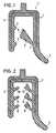
- Fig. 1 einen Querschnitt durch ein Dichtungsprofil mit einer dreieckförmigen Dichtlippe und
- Fig. 2 einen Querschnitt durch ein Dichtungsprofil mit mehreren Dichtlippen.
- Fig. 1 shows a cross section through a sealing profile with a triangular sealing lip and
- Fig. 2 shows a cross section through a sealing profile with several sealing lips.
Wie man aus Fig. 1 ersieht, weist das Dichtungsprofil 1 einen U-förmigen Grundkörper 2 mit einer metallischen Verstärkungseinlage 3 auf. Auf der Innenseite dieses Grundkörpers 2 sind an der einen Innenfläche zwei kleine wulstförmige Dichtlippen 4 und 5 vorgesehen, während an der anderen Innenfläche eine angenähert dreieckförmige größere Dichtlippe 6 über einen schmalen Verbindungssteg 7 angelenkt ist. Diese Dichtlippe 6 ist an ihrem verbreiterten Kopfbereich mit einer konkav gewölbten Einziehung 8 versehen. Insgesamt verläuft diese Kopffläche im unbelasteten Zustand schräg im Winkel zu einer gedachten Mittelebene des U-förmigen Grundkörpers 2.As can be seen from Fig. 1, the sealing profile 1 has a U-shaped base body 2 with a metallic reinforcing
Beim Aufschieben dieses Dichtungsprofils 1 auf eine nicht näher dargestellte Blechkante setzt die Dichtlippe 6 diesem nur einen geringen Widerstand entgegen, da einmal nur eine geringe Berührungsfläche und damit Reibungsfläche zwischen einzuschiebendem Blech und Dichtlippe 6 besteht und zum anderen die Dichtlippe 6 nach innen klappt. Beim Abziehen des Dichtungsprofils 1 verkeilt sich jedoch die Dichtlippe 6 mit dem Blechbord und setzt damit dem Abziehen einen erheblichen Widerstand entgegen. Da die Dichtlippe einstückig und damit aus dem gleichen Material wie der Grundkörper 2 gefertigt ist, ist diese auch somit relativ steif und kann sich nicht aufrollen, sondern wirkt wie ein echter Keil, so daß ein Abziehen nur mit erheblichem Aufwand möglich ist. Durch die Gestaltung der Dichtlippe 6 und ihrer Anordnung im Grundkörper 2 wird die gleiche Verkeilwirkung auch bei Blechen unterschiedlicher Dicke erreicht, so daß ein derartiges Profil sehr universell eingesetzt werden kann.When this sealing profile 1 is pushed onto a sheet metal edge (not shown in detail), the sealing lip 6 opposes this only with a slight resistance, since there is only a small contact surface and thus friction surface between the sheet to be inserted and the sealing lip 6 and, on the other hand, the sealing lip 6 folds inwards. When pulling off the sealing profile 1, however, the sealing lip 6 wedges with the sheet metal rim and thus opposes the pulling off a considerable resistance. Since the sealing lip is made in one piece and thus from the same material as the base body 2, it is also relatively stiff and cannot roll up, but acts like a real wedge, so that it can only be removed with considerable effort. Due to the design of the sealing lip 6 and its arrangement in the base body 2, the same wedging effect is achieved even with sheets of different thicknesses, so that such a profile can be used very universally.
Nach dem in Fig. 2 dargestellten Ausführungsbeispiel weist der Grundkörper 2 auf seiner einen Innenseite drei herkömmliche, spitz zulaufende Dichtlippen 10, 11 und 12 und auf der anderen Innenfläche drei dreieckförmige Dichtlippen 13, 14 und 15 auf. Mit einer derartigen Ausbildung ist einmal ein noch festerer Sitz und zum anderen eine bessere Abdichtung gegen eintretende Feuchtigkeit sicher gewährleistet.According to the exemplary embodiment shown in FIG. 2, the base body 2 has three conventional, tapered sealing
Darüber hinaus kann in herkömmlicher Weise einer der U-förmigen Schenkel des Grundkörpers 2 zu einer abragenden flexiblen Dichtleiste 9 verlängert sein. Diese zusätzliche Dichtleiste kann auch an jeder anderen Stelle vom Grundkörper 2 des Profils abragen.In addition, one of the U-shaped legs of the base body 2 can be extended to a protruding flexible sealing strip 9 in a conventional manner. This additional sealing strip can also protrude from the base body 2 of the profile at any other point.
Insgesamt ergibt sich also ein Dichtungsprofil, das sehr leicht aufzuschieben ist und bei dem nicht mehr wie bei herkömmlichen Profilen drei verschiedene Gummiqualitäten für Grundkörper und Lippen erforderlich sind, da die Dichtlippen -aus dem gleichen Material wie der Grundkörper selbst bestehen. Darüber hinaus lassen sich Dichtlippen mit verbreitertem Kopf, die einstückig mit dem Grundkörper verbunden sind, leichter herstellen als spitz zulaufende Lippen und bieten gegen das Herausziehen durch ihre Klemmwirkung einen erheblich größeren Widerstand.Overall, this results in a sealing profile that is very easy to slide on and in which three different rubber qualities are no longer required for the base body and lips, as is the case with conventional profiles, since the sealing lips are made of the same material as the base body itself. In addition, sealing lips with a widened head, which are integrally connected to the base body, are easier to produce than tapered lips and offer a considerably greater resistance to being pulled out due to their clamping action.
Claims (5)
Applications Claiming Priority (3)
| Application Number | Priority Date | Filing Date | Title |
|---|---|---|---|
| DE8620972UDE8620972U1 (en) | 1986-08-05 | 1986-08-05 | Sealing profile |
| DE19863626457DE3626457A1 (en) | 1986-08-05 | 1986-08-05 | GASKET PROFILE |
| DE3626457 | 1986-08-05 |
Publications (2)
| Publication Number | Publication Date |
|---|---|
| EP0255916A1 EP0255916A1 (en) | 1988-02-17 |
| EP0255916B1true EP0255916B1 (en) | 1990-02-07 |
Family
ID=25846241
Family Applications (1)
| Application Number | Title | Priority Date | Filing Date |
|---|---|---|---|
| EP87110973AExpired - LifetimeEP0255916B1 (en) | 1986-08-05 | 1987-07-29 | Sealing strip for fitting on the edge of the bodyworkof a car |
Country Status (5)
| Country | Link |
|---|---|
| US (1) | US4744570A (en) |
| EP (1) | EP0255916B1 (en) |
| JP (1) | JPS6343064A (en) |
| DE (2) | DE8620972U1 (en) |
| ES (1) | ES2016826B3 (en) |
Cited By (2)
| Publication number | Priority date | Publication date | Assignee | Title |
|---|---|---|---|---|
| DE102009032877A1 (en)* | 2009-07-13 | 2011-01-27 | Metzeler Automotive Profile Systems Gmbh | Method for manufacturing sealing or cover strip of car, involves pressing retaining lip into insertion channel after vulcanization of insert area, and holding retaining lip by side section in prestressed position |
| DE102009032876A1 (en) | 2009-07-13 | 2011-02-03 | Metzeler Automotive Profile Systems Gmbh | Method for producing a sealing or masking strip and sealing or cover strip obtainable therewith |
Families Citing this family (16)
| Publication number | Priority date | Publication date | Assignee | Title |
|---|---|---|---|---|
| CA1316967C (en)* | 1987-09-16 | 1993-04-27 | Richard Douglas Martin | Flange finisher with weatherstrip |
| FR2629128B1 (en)* | 1988-03-28 | 1993-10-08 | Mesnel Ets | SEAL FOR VEHICLE TRUNK, ESPECIALLY FOR AUTOMOBILE TRUNK |
| US5085006A (en)* | 1989-04-24 | 1992-02-04 | Toyoda Gosei Co., Ltd. | Weather strip for motor vehicle |
| US5267739A (en)* | 1990-02-07 | 1993-12-07 | The Standard Products Company | Engine compartment seal |
| GB9226324D0 (en)* | 1992-12-17 | 1993-02-10 | Draftex Ind Ltd | Sealing,trimming and finishing strips |
| US5605370A (en)* | 1994-02-07 | 1997-02-25 | Ruiz; Carmelo C. | Window shade and vehicle window combination |
| DE29723953U1 (en)* | 1996-10-24 | 1999-07-29 | Minnesota Mining & Manufacturing Company, St. Paul, Minnesota | Vehicle with a filter device for filtering a fluid |
| DE29621997U1 (en)* | 1996-12-19 | 1998-02-19 | Meteor Gummiwerke K. H. Bädje GmbH & Co, 31167 Bockenem | Sealing system for the roof frame of a hardtop or coupe or a folding top |
| DE19711487C2 (en)* | 1997-03-19 | 2001-10-11 | Metzeler Automotive Profiles | Sealing profile for motor vehicles |
| US6247271B1 (en)* | 1997-09-24 | 2001-06-19 | Ford Global Technologies, Inc. | Automotive door seal for accommodating weld flanges having different thicknesses |
| GB2370307A (en)* | 2000-12-21 | 2002-06-26 | Draftex Ind Ltd | Sealing or trim strip with pivoting limbs to grip a flange |
| US7413099B2 (en)* | 2001-06-08 | 2008-08-19 | Shin-Etsu Polymer Co., Ltd. | Sealing element with a protruding part approximately obliquely outward and a hermetic container using the same |
| US7919003B2 (en)* | 2005-07-19 | 2011-04-05 | Hydro Component Systems, Llc | Protective sleeve for intake rack bars |
| US7828302B2 (en)* | 2007-08-15 | 2010-11-09 | Federal-Mogul Corporation | Lateral sealing gasket and method |
| US7975870B2 (en)* | 2007-08-29 | 2011-07-12 | Ti Group Automotive Systems, L.L.C. | Ring seal having sealing lobes |
| US8499499B2 (en)* | 2011-09-27 | 2013-08-06 | Toyoda Gosei Co., Ltd. | Weather strip for motor vehicle |
Family Cites Families (16)
| Publication number | Priority date | Publication date | Assignee | Title |
|---|---|---|---|---|
| US2492566A (en)* | 1947-04-22 | 1949-12-27 | Gen Motors Corp | Connector strip |
| US2625716A (en)* | 1950-01-14 | 1953-01-20 | Gen Tire & Rubber Co | Flexible windshield mounting |
| DE916501C (en)* | 1952-11-21 | 1954-08-12 | Uerdingen Ag Waggonfabrik | Edging profile for vehicle glazing, especially for windshields |
| NL281193A (en)* | 1962-07-20 | |||
| DE1938223C3 (en)* | 1969-07-24 | 1975-09-18 | Draftex Gmbh, 4060 Viersen | U-shaped profiled protective and sealing strips that can be placed on a support flange |
| US3755873A (en)* | 1972-04-27 | 1973-09-04 | Schlegel Mfg Co | Weatherstrip assembly apparatus |
| US4014556A (en)* | 1976-03-03 | 1977-03-29 | Clow Corporation | Sealing ring means for pipe couplings |
| FR2406766A1 (en)* | 1977-10-18 | 1979-05-18 | Profil Sa Ind Financ Le | PROTECTION AND SEALING TAPE FOR METAL OR SIMILAR EDGES |
| GB2026579B (en)* | 1978-07-29 | 1982-10-27 | Draftex Dev Ag | Channel-shaped sealing strips |
| DE3003808A1 (en)* | 1980-02-02 | 1981-08-13 | Continental Gummi-Werke Ag, 3000 Hannover | Reinforced trim strip for windows - has retaining ribs with extension lips seating against glass via widened ends |
| JPS5758509A (en)* | 1980-09-22 | 1982-04-08 | Nissan Motor Co Ltd | Window glass attaching structure |
| DE3114157A1 (en)* | 1981-04-08 | 1982-10-28 | Otto Schwendt KG, 5620 Velbert | Edge trim for seams |
| FR2532599A1 (en)* | 1982-09-07 | 1984-03-09 | Mesnel Sa Ets | BODY JOINTS, IN PARTICULAR FOR AUTOMOBILES, WITH IMPROVED FLEXIBLE LIPS |
| DE3239752A1 (en)* | 1982-10-27 | 1984-05-03 | Volkswagenwerk Ag, 3180 Wolfsburg | PROFILE STRIP MADE OF RUBBER OR PLASTIC |
| US4447065A (en)* | 1983-02-28 | 1984-05-08 | The General Tire & Rubber Company | Sealing strip |
| GB2172640B (en)* | 1985-03-21 | 1988-04-27 | Silent Channel Prod Ltd | Sealing strip |
- 1986
- 1986-08-05DEDE8620972Upatent/DE8620972U1/ennot_activeExpired
- 1986-08-05DEDE19863626457patent/DE3626457A1/ennot_activeCeased
- 1987
- 1987-07-29ESES87110973Tpatent/ES2016826B3/ennot_activeExpired - Lifetime
- 1987-07-29EPEP87110973Apatent/EP0255916B1/ennot_activeExpired - Lifetime
- 1987-08-03JPJP62194265Apatent/JPS6343064A/enactivePending
- 1987-08-04USUS07/081,186patent/US4744570A/ennot_activeExpired - Fee Related
Cited By (2)
| Publication number | Priority date | Publication date | Assignee | Title |
|---|---|---|---|---|
| DE102009032877A1 (en)* | 2009-07-13 | 2011-01-27 | Metzeler Automotive Profile Systems Gmbh | Method for manufacturing sealing or cover strip of car, involves pressing retaining lip into insertion channel after vulcanization of insert area, and holding retaining lip by side section in prestressed position |
| DE102009032876A1 (en) | 2009-07-13 | 2011-02-03 | Metzeler Automotive Profile Systems Gmbh | Method for producing a sealing or masking strip and sealing or cover strip obtainable therewith |
Also Published As
| Publication number | Publication date |
|---|---|
| US4744570A (en) | 1988-05-17 |
| DE3626457A1 (en) | 1988-02-18 |
| JPS6343064A (en) | 1988-02-24 |
| EP0255916A1 (en) | 1988-02-17 |
| ES2016826B3 (en) | 1990-12-01 |
| DE8620972U1 (en) | 1987-03-26 |
Similar Documents
| Publication | Publication Date | Title |
|---|---|---|
| EP0255916B1 (en) | Sealing strip for fitting on the edge of the bodyworkof a car | |
| DE8503538U1 (en) | SEALING ELEMENT BETWEEN A DOOR AND THE RELATED PLANT SHOULDER IN A CABINET, ESPECIALLY A REFRIGERATOR | |
| CH677388A5 (en) | ||
| CH676376A5 (en) | Strip-type door-leaf seal | |
| DE19847955A1 (en) | Sealing profile for window or door | |
| AT404965B (en) | GLASS FOLDED GASKET, ESPECIALLY FOR WINDOWS AND DOORS | |
| DE19539906C1 (en) | Elastic strip seal for window glazing | |
| EP0881350B1 (en) | Door with a sealing | |
| DE3503227A1 (en) | Frame profile | |
| DE2755321A1 (en) | SEALING STRIPS FOR WINDOWS OR DOORS | |
| DE2501710C3 (en) | Sealing strip | |
| DE2808386B2 (en) | Device for bridging expansion joints, especially in bridges, road sections or the like | |
| DE3337438A1 (en) | Profiled strip | |
| DE3239395A1 (en) | Profiled strip | |
| WO2014015855A2 (en) | Insertion tool | |
| AT409524B (en) | PROFILE SEAL | |
| DE60202279T2 (en) | FRAME FOR FIXING A PLATE-TABLE TABLE | |
| DE2061716B2 (en) | Window or door wing sealing unit - has pressed strip connecting section through stem on shaped retaining batten | |
| DE2300833C3 (en) | Sealing device for doors | |
| DE8131774U1 (en) | "SEALING PROFILE" | |
| CH661317A5 (en) | DOOR SEAL. | |
| DE29718780U1 (en) | Louvre window | |
| DE3506974C2 (en) | ||
| EP1596031A2 (en) | Extruded elastic sealing for windows, doors or the same | |
| DE1922789C3 (en) | One-piece sealing strip made of elastomer for doors or other closures |
Legal Events
| Date | Code | Title | Description |
|---|---|---|---|
| PUAI | Public reference made under article 153(3) epc to a published international application that has entered the european phase | Free format text:ORIGINAL CODE: 0009012 | |
| 17P | Request for examination filed | Effective date:19870729 | |
| AK | Designated contracting states | Kind code of ref document:A1 Designated state(s):DE ES FR GB IT | |
| RAP1 | Party data changed (applicant data changed or rights of an application transferred) | Owner name:METZELER GESELLSCHAFT MIT BESCHRAENKTER HAFTUNG | |
| 17Q | First examination report despatched | Effective date:19890214 | |
| GRAA | (expected) grant | Free format text:ORIGINAL CODE: 0009210 | |
| AK | Designated contracting states | Kind code of ref document:B1 Designated state(s):DE ES FR GB IT | |
| REF | Corresponds to: | Ref document number:3761638 Country of ref document:DE Date of ref document:19900315 | |
| ITF | It: translation for a ep patent filed | ||
| ET | Fr: translation filed | ||
| GBT | Gb: translation of ep patent filed (gb section 77(6)(a)/1977) | ||
| PLBE | No opposition filed within time limit | Free format text:ORIGINAL CODE: 0009261 | |
| STAA | Information on the status of an ep patent application or granted ep patent | Free format text:STATUS: NO OPPOSITION FILED WITHIN TIME LIMIT | |
| 26N | No opposition filed | ||
| ITTA | It: last paid annual fee | ||
| ITPR | It: changes in ownership of a european patent | Owner name:CAMBIO RAGIONE SOCIALE;METZELER AUTOMOTIVE PROFILE | |
| REG | Reference to a national code | Ref country code:FR Ref legal event code:CD Ref country code:FR Ref legal event code:CA | |
| REG | Reference to a national code | Ref country code:ES Ref legal event code:PC2A Owner name:METZELER AUTOMOTIVE PROFILES GMBH. | |
| PGFP | Annual fee paid to national office [announced via postgrant information from national office to epo] | Ref country code:FR Payment date:19940711 Year of fee payment:8 | |
| PGFP | Annual fee paid to national office [announced via postgrant information from national office to epo] | Ref country code:GB Payment date:19940719 Year of fee payment:8 | |
| PGFP | Annual fee paid to national office [announced via postgrant information from national office to epo] | Ref country code:DE Payment date:19940721 Year of fee payment:8 | |
| PGFP | Annual fee paid to national office [announced via postgrant information from national office to epo] | Ref country code:ES Payment date:19940730 Year of fee payment:8 | |
| PG25 | Lapsed in a contracting state [announced via postgrant information from national office to epo] | Ref country code:GB Effective date:19950729 | |
| PG25 | Lapsed in a contracting state [announced via postgrant information from national office to epo] | Ref country code:ES Free format text:LAPSE BECAUSE OF THE APPLICANT RENOUNCES Effective date:19950731 | |
| GBPC | Gb: european patent ceased through non-payment of renewal fee | Effective date:19950729 | |
| PG25 | Lapsed in a contracting state [announced via postgrant information from national office to epo] | Ref country code:DE Effective date:19960402 | |
| PG25 | Lapsed in a contracting state [announced via postgrant information from national office to epo] | Ref country code:FR Effective date:19960430 | |
| REG | Reference to a national code | Ref country code:FR Ref legal event code:ST | |
| REG | Reference to a national code | Ref country code:FR Ref legal event code:ST | |
| REG | Reference to a national code | Ref country code:FR Ref legal event code:ST | |
| REG | Reference to a national code | Ref country code:ES Ref legal event code:FD2A Effective date:19991007 | |
| PG25 | Lapsed in a contracting state [announced via postgrant information from national office to epo] | Ref country code:IT Free format text:LAPSE BECAUSE OF NON-PAYMENT OF DUE FEES;WARNING: LAPSES OF ITALIAN PATENTS WITH EFFECTIVE DATE BEFORE 2007 MAY HAVE OCCURRED AT ANY TIME BEFORE 2007. THE CORRECT EFFECTIVE DATE MAY BE DIFFERENT FROM THE ONE RECORDED. Effective date:20050729 |