EP0244222B1 - System for controlling a clutch for a motor vehicle - Google Patents
System for controlling a clutch for a motor vehicleDownload PDFInfo
- Publication number
- EP0244222B1 EP0244222B1EP87303806AEP87303806AEP0244222B1EP 0244222 B1EP0244222 B1EP 0244222B1EP 87303806 AEP87303806 AEP 87303806AEP 87303806 AEP87303806 AEP 87303806AEP 0244222 B1EP0244222 B1EP 0244222B1
- Authority
- EP
- European Patent Office
- Prior art keywords
- clutch
- signal
- mode
- engine speed
- engine
- Prior art date
- Legal status (The legal status is an assumption and is not a legal conclusion. Google has not performed a legal analysis and makes no representation as to the accuracy of the status listed.)
- Expired - Lifetime
Links
- 230000005540biological transmissionEffects0.000claimsdescription20
- 230000004044responseEffects0.000claimsdescription7
- 230000007257malfunctionEffects0.000claimsdescription4
- 230000005284excitationEffects0.000description6
- 230000007246mechanismEffects0.000description5
- 239000000843powderSubstances0.000description4
- 230000001419dependent effectEffects0.000description3
- 230000006866deteriorationEffects0.000description2
- 238000010586diagramMethods0.000description2
- 230000004907fluxEffects0.000description2
- 230000002159abnormal effectEffects0.000description1
- 230000008859changeEffects0.000description1
- 230000007423decreaseEffects0.000description1
- 230000003247decreasing effectEffects0.000description1
- 230000000994depressogenic effectEffects0.000description1
- 239000000696magnetic materialSubstances0.000description1
- 239000006247magnetic powderSubstances0.000description1
- 230000007935neutral effectEffects0.000description1
- 230000009467reductionEffects0.000description1
Images


Classifications
- F—MECHANICAL ENGINEERING; LIGHTING; HEATING; WEAPONS; BLASTING
- F16—ENGINEERING ELEMENTS AND UNITS; GENERAL MEASURES FOR PRODUCING AND MAINTAINING EFFECTIVE FUNCTIONING OF MACHINES OR INSTALLATIONS; THERMAL INSULATION IN GENERAL
- F16H—GEARING
- F16H61/00—Control functions within control units of change-speed- or reversing-gearings for conveying rotary motion ; Control of exclusively fluid gearing, friction gearing, gearings with endless flexible members or other particular types of gearing
- F16H61/66—Control functions within control units of change-speed- or reversing-gearings for conveying rotary motion ; Control of exclusively fluid gearing, friction gearing, gearings with endless flexible members or other particular types of gearing specially adapted for continuously variable gearings
- B—PERFORMING OPERATIONS; TRANSPORTING
- B60—VEHICLES IN GENERAL
- B60W—CONJOINT CONTROL OF VEHICLE SUB-UNITS OF DIFFERENT TYPE OR DIFFERENT FUNCTION; CONTROL SYSTEMS SPECIALLY ADAPTED FOR HYBRID VEHICLES; ROAD VEHICLE DRIVE CONTROL SYSTEMS FOR PURPOSES NOT RELATED TO THE CONTROL OF A PARTICULAR SUB-UNIT
- B60W10/00—Conjoint control of vehicle sub-units of different type or different function
- B60W10/02—Conjoint control of vehicle sub-units of different type or different function including control of driveline clutches
- B—PERFORMING OPERATIONS; TRANSPORTING
- B60—VEHICLES IN GENERAL
- B60W—CONJOINT CONTROL OF VEHICLE SUB-UNITS OF DIFFERENT TYPE OR DIFFERENT FUNCTION; CONTROL SYSTEMS SPECIALLY ADAPTED FOR HYBRID VEHICLES; ROAD VEHICLE DRIVE CONTROL SYSTEMS FOR PURPOSES NOT RELATED TO THE CONTROL OF A PARTICULAR SUB-UNIT
- B60W10/00—Conjoint control of vehicle sub-units of different type or different function
- B60W10/04—Conjoint control of vehicle sub-units of different type or different function including control of propulsion units
- B60W10/06—Conjoint control of vehicle sub-units of different type or different function including control of propulsion units including control of combustion engines
- B—PERFORMING OPERATIONS; TRANSPORTING
- B60—VEHICLES IN GENERAL
- B60W—CONJOINT CONTROL OF VEHICLE SUB-UNITS OF DIFFERENT TYPE OR DIFFERENT FUNCTION; CONTROL SYSTEMS SPECIALLY ADAPTED FOR HYBRID VEHICLES; ROAD VEHICLE DRIVE CONTROL SYSTEMS FOR PURPOSES NOT RELATED TO THE CONTROL OF A PARTICULAR SUB-UNIT
- B60W10/00—Conjoint control of vehicle sub-units of different type or different function
- B60W10/10—Conjoint control of vehicle sub-units of different type or different function including control of change-speed gearings
- B60W10/101—Infinitely variable gearings
- B60W10/107—Infinitely variable gearings with endless flexible members
- F—MECHANICAL ENGINEERING; LIGHTING; HEATING; WEAPONS; BLASTING
- F16—ENGINEERING ELEMENTS AND UNITS; GENERAL MEASURES FOR PRODUCING AND MAINTAINING EFFECTIVE FUNCTIONING OF MACHINES OR INSTALLATIONS; THERMAL INSULATION IN GENERAL
- F16D—COUPLINGS FOR TRANSMITTING ROTATION; CLUTCHES; BRAKES
- F16D48/00—External control of clutches
- F16D48/06—Control by electric or electronic means, e.g. of fluid pressure
- B—PERFORMING OPERATIONS; TRANSPORTING
- B60—VEHICLES IN GENERAL
- B60W—CONJOINT CONTROL OF VEHICLE SUB-UNITS OF DIFFERENT TYPE OR DIFFERENT FUNCTION; CONTROL SYSTEMS SPECIALLY ADAPTED FOR HYBRID VEHICLES; ROAD VEHICLE DRIVE CONTROL SYSTEMS FOR PURPOSES NOT RELATED TO THE CONTROL OF A PARTICULAR SUB-UNIT
- B60W50/00—Details of control systems for road vehicle drive control not related to the control of a particular sub-unit, e.g. process diagnostic or vehicle driver interfaces
- B60W50/02—Ensuring safety in case of control system failures, e.g. by diagnosing, circumventing or fixing failures
- B60W50/0205—Diagnosing or detecting failures; Failure detection models
- B60W2050/021—Means for detecting failure or malfunction
- B—PERFORMING OPERATIONS; TRANSPORTING
- B60—VEHICLES IN GENERAL
- B60W—CONJOINT CONTROL OF VEHICLE SUB-UNITS OF DIFFERENT TYPE OR DIFFERENT FUNCTION; CONTROL SYSTEMS SPECIALLY ADAPTED FOR HYBRID VEHICLES; ROAD VEHICLE DRIVE CONTROL SYSTEMS FOR PURPOSES NOT RELATED TO THE CONTROL OF A PARTICULAR SUB-UNIT
- B60W2510/00—Input parameters relating to a particular sub-units
- B60W2510/06—Combustion engines, Gas turbines
- B60W2510/0638—Engine speed
- B—PERFORMING OPERATIONS; TRANSPORTING
- B60—VEHICLES IN GENERAL
- B60W—CONJOINT CONTROL OF VEHICLE SUB-UNITS OF DIFFERENT TYPE OR DIFFERENT FUNCTION; CONTROL SYSTEMS SPECIALLY ADAPTED FOR HYBRID VEHICLES; ROAD VEHICLE DRIVE CONTROL SYSTEMS FOR PURPOSES NOT RELATED TO THE CONTROL OF A PARTICULAR SUB-UNIT
- B60W2510/00—Input parameters relating to a particular sub-units
- B60W2510/10—Change speed gearings
- B60W2510/104—Output speed
- B—PERFORMING OPERATIONS; TRANSPORTING
- B60—VEHICLES IN GENERAL
- B60W—CONJOINT CONTROL OF VEHICLE SUB-UNITS OF DIFFERENT TYPE OR DIFFERENT FUNCTION; CONTROL SYSTEMS SPECIALLY ADAPTED FOR HYBRID VEHICLES; ROAD VEHICLE DRIVE CONTROL SYSTEMS FOR PURPOSES NOT RELATED TO THE CONTROL OF A PARTICULAR SUB-UNIT
- B60W2540/00—Input parameters relating to occupants
- B60W2540/10—Accelerator pedal position
- F—MECHANICAL ENGINEERING; LIGHTING; HEATING; WEAPONS; BLASTING
- F16—ENGINEERING ELEMENTS AND UNITS; GENERAL MEASURES FOR PRODUCING AND MAINTAINING EFFECTIVE FUNCTIONING OF MACHINES OR INSTALLATIONS; THERMAL INSULATION IN GENERAL
- F16D—COUPLINGS FOR TRANSMITTING ROTATION; CLUTCHES; BRAKES
- F16D2500/00—External control of clutches by electric or electronic means
- F16D2500/10—System to be controlled
- F16D2500/108—Gear
- F16D2500/1088—CVT
- F—MECHANICAL ENGINEERING; LIGHTING; HEATING; WEAPONS; BLASTING
- F16—ENGINEERING ELEMENTS AND UNITS; GENERAL MEASURES FOR PRODUCING AND MAINTAINING EFFECTIVE FUNCTIONING OF MACHINES OR INSTALLATIONS; THERMAL INSULATION IN GENERAL
- F16D—COUPLINGS FOR TRANSMITTING ROTATION; CLUTCHES; BRAKES
- F16D2500/00—External control of clutches by electric or electronic means
- F16D2500/30—Signal inputs
- F16D2500/306—Signal inputs from the engine
- F16D2500/3067—Speed of the engine
- F—MECHANICAL ENGINEERING; LIGHTING; HEATING; WEAPONS; BLASTING
- F16—ENGINEERING ELEMENTS AND UNITS; GENERAL MEASURES FOR PRODUCING AND MAINTAINING EFFECTIVE FUNCTIONING OF MACHINES OR INSTALLATIONS; THERMAL INSULATION IN GENERAL
- F16D—COUPLINGS FOR TRANSMITTING ROTATION; CLUTCHES; BRAKES
- F16D2500/00—External control of clutches by electric or electronic means
- F16D2500/30—Signal inputs
- F16D2500/308—Signal inputs from the transmission
- F16D2500/3081—Signal inputs from the transmission from the input shaft
- F16D2500/30816—Speed of the input shaft
- F—MECHANICAL ENGINEERING; LIGHTING; HEATING; WEAPONS; BLASTING
- F16—ENGINEERING ELEMENTS AND UNITS; GENERAL MEASURES FOR PRODUCING AND MAINTAINING EFFECTIVE FUNCTIONING OF MACHINES OR INSTALLATIONS; THERMAL INSULATION IN GENERAL
- F16D—COUPLINGS FOR TRANSMITTING ROTATION; CLUTCHES; BRAKES
- F16D2500/00—External control of clutches by electric or electronic means
- F16D2500/30—Signal inputs
- F16D2500/308—Signal inputs from the transmission
- F16D2500/3082—Signal inputs from the transmission from the output shaft
- F16D2500/30825—Speed of the output shaft
- F—MECHANICAL ENGINEERING; LIGHTING; HEATING; WEAPONS; BLASTING
- F16—ENGINEERING ELEMENTS AND UNITS; GENERAL MEASURES FOR PRODUCING AND MAINTAINING EFFECTIVE FUNCTIONING OF MACHINES OR INSTALLATIONS; THERMAL INSULATION IN GENERAL
- F16D—COUPLINGS FOR TRANSMITTING ROTATION; CLUTCHES; BRAKES
- F16D2500/00—External control of clutches by electric or electronic means
- F16D2500/30—Signal inputs
- F16D2500/31—Signal inputs from the vehicle
- F16D2500/3108—Vehicle speed
- F—MECHANICAL ENGINEERING; LIGHTING; HEATING; WEAPONS; BLASTING
- F16—ENGINEERING ELEMENTS AND UNITS; GENERAL MEASURES FOR PRODUCING AND MAINTAINING EFFECTIVE FUNCTIONING OF MACHINES OR INSTALLATIONS; THERMAL INSULATION IN GENERAL
- F16D—COUPLINGS FOR TRANSMITTING ROTATION; CLUTCHES; BRAKES
- F16D2500/00—External control of clutches by electric or electronic means
- F16D2500/30—Signal inputs
- F16D2500/314—Signal inputs from the user
- F16D2500/31406—Signal inputs from the user input from pedals
- F16D2500/3144—Accelerator pedal position
- F—MECHANICAL ENGINEERING; LIGHTING; HEATING; WEAPONS; BLASTING
- F16—ENGINEERING ELEMENTS AND UNITS; GENERAL MEASURES FOR PRODUCING AND MAINTAINING EFFECTIVE FUNCTIONING OF MACHINES OR INSTALLATIONS; THERMAL INSULATION IN GENERAL
- F16D—COUPLINGS FOR TRANSMITTING ROTATION; CLUTCHES; BRAKES
- F16D2500/00—External control of clutches by electric or electronic means
- F16D2500/30—Signal inputs
- F16D2500/314—Signal inputs from the user
- F16D2500/3146—Signal inputs from the user input from levers
- F16D2500/31466—Gear lever
- F—MECHANICAL ENGINEERING; LIGHTING; HEATING; WEAPONS; BLASTING
- F16—ENGINEERING ELEMENTS AND UNITS; GENERAL MEASURES FOR PRODUCING AND MAINTAINING EFFECTIVE FUNCTIONING OF MACHINES OR INSTALLATIONS; THERMAL INSULATION IN GENERAL
- F16D—COUPLINGS FOR TRANSMITTING ROTATION; CLUTCHES; BRAKES
- F16D2500/00—External control of clutches by electric or electronic means
- F16D2500/50—Problem to be solved by the control system
- F16D2500/502—Relating the clutch
- F16D2500/50224—Drive-off
- F—MECHANICAL ENGINEERING; LIGHTING; HEATING; WEAPONS; BLASTING
- F16—ENGINEERING ELEMENTS AND UNITS; GENERAL MEASURES FOR PRODUCING AND MAINTAINING EFFECTIVE FUNCTIONING OF MACHINES OR INSTALLATIONS; THERMAL INSULATION IN GENERAL
- F16D—COUPLINGS FOR TRANSMITTING ROTATION; CLUTCHES; BRAKES
- F16D2500/00—External control of clutches by electric or electronic means
- F16D2500/50—Problem to be solved by the control system
- F16D2500/508—Relating driving conditions
- F16D2500/50858—Selecting a Mode of operation
- F—MECHANICAL ENGINEERING; LIGHTING; HEATING; WEAPONS; BLASTING
- F16—ENGINEERING ELEMENTS AND UNITS; GENERAL MEASURES FOR PRODUCING AND MAINTAINING EFFECTIVE FUNCTIONING OF MACHINES OR INSTALLATIONS; THERMAL INSULATION IN GENERAL
- F16D—COUPLINGS FOR TRANSMITTING ROTATION; CLUTCHES; BRAKES
- F16D2500/00—External control of clutches by electric or electronic means
- F16D2500/50—Problem to be solved by the control system
- F16D2500/51—Relating safety
- F16D2500/5102—Detecting abnormal operation, e.g. unwanted slip or excessive temperature
- F—MECHANICAL ENGINEERING; LIGHTING; HEATING; WEAPONS; BLASTING
- F16—ENGINEERING ELEMENTS AND UNITS; GENERAL MEASURES FOR PRODUCING AND MAINTAINING EFFECTIVE FUNCTIONING OF MACHINES OR INSTALLATIONS; THERMAL INSULATION IN GENERAL
- F16D—COUPLINGS FOR TRANSMITTING ROTATION; CLUTCHES; BRAKES
- F16D2500/00—External control of clutches by electric or electronic means
- F16D2500/50—Problem to be solved by the control system
- F16D2500/51—Relating safety
- F16D2500/5108—Failure diagnosis
- F—MECHANICAL ENGINEERING; LIGHTING; HEATING; WEAPONS; BLASTING
- F16—ENGINEERING ELEMENTS AND UNITS; GENERAL MEASURES FOR PRODUCING AND MAINTAINING EFFECTIVE FUNCTIONING OF MACHINES OR INSTALLATIONS; THERMAL INSULATION IN GENERAL
- F16D—COUPLINGS FOR TRANSMITTING ROTATION; CLUTCHES; BRAKES
- F16D2500/00—External control of clutches by electric or electronic means
- F16D2500/50—Problem to be solved by the control system
- F16D2500/51—Relating safety
- F16D2500/5114—Failsafe
- F—MECHANICAL ENGINEERING; LIGHTING; HEATING; WEAPONS; BLASTING
- F16—ENGINEERING ELEMENTS AND UNITS; GENERAL MEASURES FOR PRODUCING AND MAINTAINING EFFECTIVE FUNCTIONING OF MACHINES OR INSTALLATIONS; THERMAL INSULATION IN GENERAL
- F16D—COUPLINGS FOR TRANSMITTING ROTATION; CLUTCHES; BRAKES
- F16D2500/00—External control of clutches by electric or electronic means
- F16D2500/70—Details about the implementation of the control system
- F16D2500/704—Output parameters from the control unit; Target parameters to be controlled
- F16D2500/70422—Clutch parameters
- F16D2500/70438—From the output shaft
- F16D2500/7044—Output shaft torque
- F—MECHANICAL ENGINEERING; LIGHTING; HEATING; WEAPONS; BLASTING
- F16—ENGINEERING ELEMENTS AND UNITS; GENERAL MEASURES FOR PRODUCING AND MAINTAINING EFFECTIVE FUNCTIONING OF MACHINES OR INSTALLATIONS; THERMAL INSULATION IN GENERAL
- F16D—COUPLINGS FOR TRANSMITTING ROTATION; CLUTCHES; BRAKES
- F16D2500/00—External control of clutches by electric or electronic means
- F16D2500/70—Details about the implementation of the control system
- F16D2500/71—Actions
- F16D2500/7101—Driver alarm
- F—MECHANICAL ENGINEERING; LIGHTING; HEATING; WEAPONS; BLASTING
- F16—ENGINEERING ELEMENTS AND UNITS; GENERAL MEASURES FOR PRODUCING AND MAINTAINING EFFECTIVE FUNCTIONING OF MACHINES OR INSTALLATIONS; THERMAL INSULATION IN GENERAL
- F16H—GEARING
- F16H59/00—Control inputs to control units of change-speed- or reversing-gearings for conveying rotary motion
- F16H59/36—Inputs being a function of speed
- F16H59/44—Inputs being a function of speed dependent on machine speed, e.g. the vehicle speed
- F—MECHANICAL ENGINEERING; LIGHTING; HEATING; WEAPONS; BLASTING
- F16—ENGINEERING ELEMENTS AND UNITS; GENERAL MEASURES FOR PRODUCING AND MAINTAINING EFFECTIVE FUNCTIONING OF MACHINES OR INSTALLATIONS; THERMAL INSULATION IN GENERAL
- F16H—GEARING
- F16H61/00—Control functions within control units of change-speed- or reversing-gearings for conveying rotary motion ; Control of exclusively fluid gearing, friction gearing, gearings with endless flexible members or other particular types of gearing
- F16H61/12—Detecting malfunction or potential malfunction, e.g. fail safe ; Circumventing or fixing failures
- Y—GENERAL TAGGING OF NEW TECHNOLOGICAL DEVELOPMENTS; GENERAL TAGGING OF CROSS-SECTIONAL TECHNOLOGIES SPANNING OVER SEVERAL SECTIONS OF THE IPC; TECHNICAL SUBJECTS COVERED BY FORMER USPC CROSS-REFERENCE ART COLLECTIONS [XRACs] AND DIGESTS
- Y10—TECHNICAL SUBJECTS COVERED BY FORMER USPC
- Y10S—TECHNICAL SUBJECTS COVERED BY FORMER USPC CROSS-REFERENCE ART COLLECTIONS [XRACs] AND DIGESTS
- Y10S477/00—Interrelated power delivery controls, including engine control
- Y10S477/906—Means detecting or ameliorating the effects of malfunction or potential malfunction
Definitions
- the present inventionrelates to a control system for an electromagnetic clutch for an automatic transmission of a motor vehicle as defined in the first part of claim 1.
- An automobile provided with a continuously variable belt-drive transmission with an electromagnetic clutchis disclosed in the generic EP-A 151038.
- the electromagnetic clutch of the transmissionis controlled by a control system to provide various operational modes such as a starting mode of a vehicle, reverse excitation mode, drag mode, mode of lock-up engagement.
- One of the modesis selected in accordance with a position of a selector lever and driving conditions to control the electromagnetic clutch.
- a small reverse currentflows in a coil of the clutch to completely release a driven member of the clutch from a drive member.
- the clutch currentis increased in proportion to engine speed to start the vehicle.
- a small clutch currentflows to produce a drag torque exerted on the driven member, thereby reducing clearances formed in the power transmitting system is disengagement state of the clutch.
- a lock-up currentis provided in response to the depression of an accelerator pedal for entirely engaging the clutch.
- the start modeis changed to the clutch lock-up engagement mode, and the clutch lock-up engagement mode is changed to the drag mode at the release of the accelerator pedal.
- the vehicle speed signalis obtained by a sensor operatively connected to an output shaft of the transmission or to a speedometer. Therefore, if the vehicle speed signal is not produced because of the failure of the sensor, cut off of a cable for the speedometer, disconnected of a wiring harness, or short circuit to the ground, the control system does not properly control the clutch current. It will be understood that the fact that the vehicle speed appears to be zero means that the control system behaves as though the vehicle is stationery.
- the drag modechanges to the start mode.
- the start modeis not changed to the clutch lock-up engagement mode.
- the clutch torquechanges proportion to the engine speed because of the start mode. In such a state, it may cause the clutch to slip during the driving in accordance with driving conditions after the start of vehicle. Further, it will cause the deterioration of the clutch by excessive high temperature due to the slipping.
- clutch modeis changed to the drag mode. Accordingly, the engine braking is not effected because of disengagement of the clutch, which results in lack of safety.
- the present inventionseeks to provide a control system for a clutch which operates to detect a malfunction in a vehicle speed detecting signal system, and to provide a control system having a fail-safe function in order to maintain driveability of a vehicle under such a condition.
- the clutch torque maintaining meanscontrols the clutch torque to increase with increase of opening degree of a throttle valve of the engine
- a crankshaft 10 of an engine 1is operatively connected to an electromagnetic powder clutch 2 for transmitting the power of the engine 1 to a continuously variable belt-drive automatic transmission 4 through a selector mechanism 3.
- the output of the belt-drive automatic transmission 4is transmitted to axles 8 of vehicle driving wheels 9 through an output shaft 13, a pair of intermediate reduction gears 5, an intermediate shaft 6, and a differential 7.
- the electromagnetic powder clutch 2comprises an annular drive member 2a connected to crankshaft 10 of the engine 1, a driven member 2b secured to an input shaft 11 of the transmission 4, and a magnetizing coil 2c provided in the driven member 2b. Powder of magnetic material is provided in a gap between the drive member 2a and driven member 2b. When the magnetizing coil 2c is excited by the clutch current, driven member 2b is magnetized to produce a magnetic flux passing through the drive member 2a. The magnetic powder is aggregated in the gap by the magnetic flux and the driven member 2b is engaged with the drive member 2a by the powder. On the other hand, when the clutch current is cut off, the drive and driven members 2a and 2b are disengaged from one another.
- the selector mechanism 3is provided between the input shaft 11 and a main shaft 12.
- the selector mechanism 3is provided with a synchromesh mechanism comprising gears, hub, and sleeve for connecting the input shaft 11 and the main shaft 12 to selectively provide a driving position (D-range) and a reverse driving position (R-range).
- the continuously variable belt-drive automatic transmission 4has the main shaft 12 and the output shaft 13 provided in parallel with the main shaft 12.
- a drive pulley 14 provided with a hydraulic cylinder 14ais mounted on the main shaft 12.
- a driven pulley 15 provided with a hydraulic cylinder 15ais mounted on the output shaft 13.
- a drive belt 16engages with the drive pulley 14 and the driven pulley 15.
- Hydraulic cylinders 14a and 15aare communicated with an oil hydraulic control circuit 17.
- the hydraulic control circuit 17is responsive to vehicle speed, engine speed and throttle valve position for controlling the amount of oil supplied to the cylinders 14a and 15a.
- the pulleys 14 and 15are operated by compressive forces of cylinders so that the running diameter of belt 16 is varied to continuously change the transmission ratio.
- An electronic control system for the clutch 2 and the belt-drive automatic transmission 4has an engine speed sensor 19, and rotating speed sensors 21 and 22 for respectively sensing speeds of drive pulley 14 and the driven pulley 15.
- a choke switch 24produces an output signal when a choke valve of the engine 1 is closed, and an air conditioner switch 23 produces an output signal at the operation of an air conditioner.
- a selector lever 25 connected to the selector mechanism 3is provided with a select position sensor 26 for sensing a drive position D and a reverse position R.
- An accelerator pedal switch 28is provided for sensing the depression of an accelerator pedal 27, and a throttle position sensor 29 is provided.
- Output signals of the sensors and pulses of the switchesare applied to an electronic control unit 20 which produces a clutch current control signal to the clutch 2 and a control signal for controlling the transmission ratio (i) and a line pressure control singal to the control circuit 17.
- a transmission ratio changing speed control section 30is applied with a drive pulley speed signal N P of the sensor 21, driven pulley speed signal N s of the sensor 22, and throttle position signal ⁇ of the sensor 29 to produce the transmission ratio control signal dependent on a transmission ratio changing speed di/dt.
- the driven pulley speed signal N scomprises pulses and corresponds to vehicle speed V.
- a line pressure control section 31is applied with an engine speed signal Ne of the sensor 19, throttle position signal ⁇ of the sensor 29, actual transmission speed ratio signal i (N s /N P ) of the transmission ratio changing speed control section 30 to produce the line pressure control signal dependent on a desired line pressure.
- a reverse excitation mode deciding section 32is applied with engine speed signal Ne of the sensor 19 and drive position signal of the select position sensor 26.
- the reverse excitation mode deciding section 32produces a reverse excitation signal which is applied to an output deciding section 33, so that a small reverse current flows in the clutch 2 to release the clutch completely.
- a clutch current mode deciding section 34is applied with signals from the reverse excitation mode deciding section 32 and accelerator pedal switch 28, and vehicle speed signal V from driven pulley speed sensor 22 for deciding driving conditions such as starting node to produce output signals.
- the output signalsare applied to a start mode providing section 35, drag mode providing section 36, and clutch lock-up engage mode providing section 37.
- the start mode providing section 35decides clutch current of starting characteristic dependent on the engine speed Ne at ordinary start or at closing of the choke switch 24 or air conditioner switch 23.
- the starting characteristicis corrected by the throttle position signal ⁇ , vehicle speed signal V, and driving position signals of D-range and R-range.
- the drag mode providing section 36decides a small drag current when the accelerator pedal 27 is released at a low speed in each drive position for providing a drag torque to the clutch 2 for the smooth start of the vehicle.
- the clutch lock-up engage mode providing section 37decides a lock-up current in response to the vehicle speed signal V and throttle position signal ⁇ at each drive position for entirely engaging the clutch 2. Outputs of sections 35, 36 and 37 are applied to the output deciding section 33 to control the clutch current. A range of each mode is shown in Fig. 3.
- a diagnose and fail-safe control section 50is provided for detecting a failure of a vehicle speed signal system and for controlling a fail-safe system when the failure is detected to prevent the aggravation of driving characteristics.
- the diagnose and fail safe control section 50is provided with a vehicle speed signal system trouble detector 40 which is applied with output signals of the clutch current mode deciding section 34, engine speed Ne of the sensor 19, and vehicle speed V of the sensor 22.
- a trouble signalis applied to a fail-sale deciding section 41.
- the fail sale deciding section 41produces a fail-sale signal.
- the fail-safe signalis applied to an alarm display 43 through a trouble display deciding section 42.
- the fail-safe signalis further applied to a start current correcting section 44 which is applied with a throttle position signal ⁇ to calculate a correcting value f( ⁇ ) in response to the throttle valve opening degree.
- the correcting value f( ⁇ )is applied to the start mode providing section 35.
- a mode changing section 45is provided for determining a fail-safe flag set and produces an output signal which is applied to the clutch current mode deciding section 34.
- the mode changing section 45comprises a dummy signal output section 46 which is applied with the fail-safe signal from the fail-safe deciding section 41 and an engine speed deciding section 47 applied with the engine speed signal Ne. An output signal of the section 47 is applied to the section 46.
- a predetermined speed N2for example 1300 rpm
- the section 46produces a dummy signal resembling the depression of the accelerator pedal.
- the dummy signalis applied to the clutch current mode deciding section 34 to maintain the start mode, even if the accelerator pedal is released.
- a trouble flagis set.
- N1for example 1500 rpm
- a trouble flagis set, it is determined whether the fail-safe flag is to be set or not.
- a predetermined period T Fis set in a timer.
- the predetermined period tFis set after a timer flag is set.
- the set time in the timeris decreased to zero by a decrement at predetermined intervals.
- the timergoes to zero, that is, the start mode continues more than the predetermined period T F after the set of trouble flag, the fail-safe flag and trouble display flag are set.
- the vehicle speed pulse signalis applied to the detector 40, all flags are reset.
- the normal operationis executed.
- the alarm display 43indicates the alarm.
- the start current correcting section 44produces the correcting signal f( ⁇ ) to correct the clutch current Ic at the start mode providing section 35. Accordingly, during the drive of the vehicle after starting, the start mode is maintained by the clutch current mode deciding section 34 in spite of vehicle speed signal being zero. In this state, the clutch torque is increasingly corrected in response to the depression of the accelerator pedal in the low engine speed range so that the engagement of the clutch is maintained without slipping.
- the mode changing section 45produces an output signal, when engine speed is higher than the set speed N2.
- the dummy signal output section 46produces a dummy signal.
- the dummy signalis applied to the clutch current mode deciding section 34 to maintain the start mode.
- the clutch currentflows, even if the accelerator pedal is released, thereby effecting the engine braking.
- the trouble flag, timer flag and fail-safe flagare reset to stop producing the dummy signal.
- the systemis changed to the drag mode at the section 34.
- the drag mode currentflows in the coil of the clutch to disengage the clutch.
- the fail-safe systemis provided for correcting the clutch torque in accordance with the depression of the accelerator pedal with keeping the predetermined engine speed. Therefore, the deterioration of the clutch and the aggravation of driving characteristics are prevented.
Landscapes
- Engineering & Computer Science (AREA)
- Chemical & Material Sciences (AREA)
- Combustion & Propulsion (AREA)
- Mechanical Engineering (AREA)
- General Engineering & Computer Science (AREA)
- Transportation (AREA)
- Physics & Mathematics (AREA)
- Fluid Mechanics (AREA)
- Hydraulic Clutches, Magnetic Clutches, Fluid Clutches, And Fluid Joints (AREA)
- Arrangement And Mounting Of Devices That Control Transmission Of Motive Force (AREA)
- Control Of Driving Devices And Active Controlling Of Vehicle (AREA)
Description
- The present invention relates to a control system for an electromagnetic clutch for an automatic transmission of a motor vehicle as defined in the first part of
claim 1. - An automobile provided with a continuously variable belt-drive transmission with an electromagnetic clutch is disclosed in the generic EP-A 151038. The electromagnetic clutch of the transmission is controlled by a control system to provide various operational modes such as a starting mode of a vehicle, reverse excitation mode, drag mode, mode of lock-up engagement. One of the modes is selected in accordance with a position of a selector lever and driving conditions to control the electromagnetic clutch.
- In the reverse excitation mode, a small reverse current flows in a coil of the clutch to completely release a driven member of the clutch from a drive member. In the start mode, the clutch current is increased in proportion to engine speed to start the vehicle. In the drag mode, a small clutch current flows to produce a drag torque exerted on the driven member, thereby reducing clearances formed in the power transmitting system is disengagement state of the clutch. In the clutch lock-up engagement mode, a lock-up current is provided in response to the depression of an accelerator pedal for entirely engaging the clutch.
- Particularly, when the vehicle speed exceeds a predetermined speed, the start mode is changed to the clutch lock-up engagement mode, and the clutch lock-up engagement mode is changed to the drag mode at the release of the accelerator pedal.
- In the control system, the vehicle speed signal is obtained by a sensor operatively connected to an output shaft of the transmission or to a speedometer. Therefore, if the vehicle speed signal is not produced because of the failure of the sensor, cut off of a cable for the speedometer, disconnected of a wiring harness, or short circuit to the ground, the control system does not properly control the clutch current. It will be understood that the fact that the vehicle speed appears to be zero means that the control system behaves as though the vehicle is stationery.
- For example, when the accelerator pedal is depressed, the drag mode changes to the start mode. However the start mode is not changed to the clutch lock-up engagement mode. Although the vehicle is started normally, the clutch torque changes proportion to the engine speed because of the start mode. In such a state, it may cause the clutch to slip during the driving in accordance with driving conditions after the start of vehicle. Further, it will cause the deterioration of the clutch by excessive high temperature due to the slipping.
- When the accelerator pedal is released, clutch mode is changed to the drag mode. Accordingly, the engine braking is not effected because of disengagement of the clutch, which results in lack of safety.
- Further in accordance with the depression and release of the accelerator pedal at higher vehicle speed, the clutch is engaged or disengaged, which aggravates the driving characteristics.
- The present invention seeks to provide a control system for a clutch which operates to detect a malfunction in a vehicle speed detecting signal system, and to provide a control system having a fail-safe function in order to maintain driveability of a vehicle under such a condition.
- According to the present invention, there is provided a system for controlling a clutch for a motor vehicle as defined by the features of
claim 1. - Preferably the clutch torque maintaining means controls the clutch torque to increase with increase of opening degree of a throttle valve of the engine,
- A preferred embodiment of the invention will now be described by way of example and with reference to the accompanying drawings, wherein:
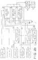
- Figure 1 is a schematic illustration of a system for controlling an electromagnetic clutch for a motor vehicle;
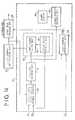
- Figures 2a and 2b show a block diagram of a control unit according to the embodiment of the present invention;
- Figure 3 is a graph showing regions of various modes;
- Figure 4 is a block diagram of a main part of the system according to the embodiment of the present invention;
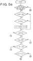
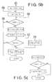
- Figures 5a to 5c are flow charts showing the operation of the system.
- Referring to Figure 1, a
crankshaft 10 of anengine 1 is operatively connected to anelectromagnetic powder clutch 2 for transmitting the power of theengine 1 to a continuously variable belt-drive automatic transmission 4 through aselector mechanism 3. The output of the belt-drive automatic transmission 4 is transmitted toaxles 8 of vehicle driving wheels 9 through anoutput shaft 13, a pair of intermediate reduction gears 5, an intermediate shaft 6, and a differential 7. - The
electromagnetic powder clutch 2 comprises anannular drive member 2a connected tocrankshaft 10 of theengine 1, a drivenmember 2b secured to aninput shaft 11 of the transmission 4, and a magnetizing coil 2c provided in the drivenmember 2b. Powder of magnetic material is provided in a gap between thedrive member 2a and drivenmember 2b. When the magnetizing coil 2c is excited by the clutch current, drivenmember 2b is magnetized to produce a magnetic flux passing through thedrive member 2a. The magnetic powder is aggregated in the gap by the magnetic flux and the drivenmember 2b is engaged with thedrive member 2a by the powder. On the other hand, when the clutch current is cut off, the drive and drivenmembers - In the belt-drive automatic transmission 4, the
selector mechanism 3 is provided between theinput shaft 11 and amain shaft 12. Theselector mechanism 3 is provided with a synchromesh mechanism comprising gears, hub, and sleeve for connecting theinput shaft 11 and themain shaft 12 to selectively provide a driving position (D-range) and a reverse driving position (R-range). - The continuously variable belt-drive automatic transmission 4 has the
main shaft 12 and theoutput shaft 13 provided in parallel with themain shaft 12. Adrive pulley 14 provided with a hydraulic cylinder 14a is mounted on themain shaft 12. A drivenpulley 15 provided with ahydraulic cylinder 15a is mounted on theoutput shaft 13. Adrive belt 16 engages with thedrive pulley 14 and the drivenpulley 15.Hydraulic cylinders 14a and 15a are communicated with an oilhydraulic control circuit 17. Thehydraulic control circuit 17 is responsive to vehicle speed, engine speed and throttle valve position for controlling the amount of oil supplied to thecylinders 14a and 15a. Thepulleys belt 16 is varied to continuously change the transmission ratio. - An electronic control system for the
clutch 2 and the belt-drive automatic transmission 4 has anengine speed sensor 19, and rotatingspeed sensors drive pulley 14 and the drivenpulley 15. Achoke switch 24 produces an output signal when a choke valve of theengine 1 is closed, and anair conditioner switch 23 produces an output signal at the operation of an air conditioner. Aselector lever 25 connected to theselector mechanism 3 is provided with aselect position sensor 26 for sensing a drive position D and a reverse position R. Anaccelerator pedal switch 28 is provided for sensing the depression of anaccelerator pedal 27, and athrottle position sensor 29 is provided. - Output signals of the sensors and pulses of the switches are applied to an
electronic control unit 20 which produces a clutch current control signal to theclutch 2 and a control signal for controlling the transmission ratio (i) and a line pressure control singal to thecontrol circuit 17. - Referring to Figs. 2a and 2b showing the
control unit 20 of Fig. 1, a transmission ratio changingspeed control section 30 is applied with a drive pulley speed signal NP of thesensor 21, driven pulley speed signal Ns of thesensor 22, and throttle position signal ϑ of thesensor 29 to produce the transmission ratio control signal dependent on a transmission ratio changing speed di/dt. The driven pulley speed signal Ns comprises pulses and corresponds to vehicle speed V. A line pressure control section 31 is applied with an engine speed signal Ne of thesensor 19, throttle position signal ϑ of thesensor 29, actual transmission speed ratio signal i (Ns/NP) of the transmission ratio changingspeed control section 30 to produce the line pressure control signal dependent on a desired line pressure. These control signals are supplied to thecontrol circuit 17 to control the transmission ratio and line pressure of the transmission 4. - A reverse excitation
mode deciding section 32 is applied with engine speed signal Ne of thesensor 19 and drive position signal of theselect position sensor 26. When the engine speed Ne is below 300 rpm, or theselector lever 25 is at a neutral position (N-range) or a parking position (P-range) , the reverse excitationmode deciding section 32 produces a reverse excitation signal which is applied to an output deciding section 33, so that a small reverse current flows in theclutch 2 to release the clutch completely. - A clutch current
mode deciding section 34 is applied with signals from the reverse excitationmode deciding section 32 andaccelerator pedal switch 28, and vehicle speed signal V from drivenpulley speed sensor 22 for deciding driving conditions such as starting node to produce output signals. The output signals are applied to a startmode providing section 35, dragmode providing section 36, and clutch lock-up engagemode providing section 37. - The start
mode providing section 35 decides clutch current of starting characteristic dependent on the engine speed Ne at ordinary start or at closing of thechoke switch 24 orair conditioner switch 23. The starting characteristic is corrected by the throttle position signal ϑ, vehicle speed signal V, and driving position signals of D-range and R-range. - The drag
mode providing section 36 decides a small drag current when theaccelerator pedal 27 is released at a low speed in each drive position for providing a drag torque to theclutch 2 for the smooth start of the vehicle. - The clutch lock-up engage
mode providing section 37 decides a lock-up current in response to the vehicle speed signal V and throttle position signal ϑ at each drive position for entirely engaging theclutch 2. Outputs ofsections - A diagnose and fail-
safe control section 50 is provided for detecting a failure of a vehicle speed signal system and for controlling a fail-safe system when the failure is detected to prevent the aggravation of driving characteristics. - Referring to Fig. 4, the diagnose and fail
safe control section 50 is provided with a vehicle speed signalsystem trouble detector 40 which is applied with output signals of the clutch currentmode deciding section 34, engine speed Ne of thesensor 19, and vehicle speed V of thesensor 22. When thedetector 40 detects an abnormal vehicle speed signal Va, a trouble signal is applied to a fail-sale deciding section 41. When the trouble signal continues for a predetermined period, the failsale deciding section 41 produces a fail-sale signal. - The fail-safe signal is applied to an
alarm display 43 through a troubledisplay deciding section 42. - The fail-safe signal is further applied to a start current correcting
section 44 which is applied with a throttle position signal ϑ to calculate a correcting value f(ϑ) in response to the throttle valve opening degree. The correcting value f(ϑ) is applied to the startmode providing section 35. At thesection 35, the clutch current Ic is given by a coefficient of engine speed f(Ne) and the correcting value f(ϑ), that is corrected by the calculation
- A
mode changing section 45 is provided for determining a fail-safe flag set and produces an output signal which is applied to the clutch currentmode deciding section 34. Themode changing section 45 comprises a dummysignal output section 46 which is applied with the fail-safe signal from the fail-safe decidingsection 41 and an enginespeed deciding section 47 applied with the engine speed signal Ne. An output signal of thesection 47 is applied to thesection 46. When the fail-safe signal is applied to thesection 46 and the engine speed is higher than a predetermined speed N2 (for example 1300 rpm), thesection 46 produces a dummy signal resembling the depression of the accelerator pedal. The dummy signal is applied to the clutch currentmode deciding section 34 to maintain the start mode, even if the accelerator pedal is released. - The operations of the
detector 40 andsection 41 of the control system will be described with reference to Figs. 5a to 5c. When the vehicle speed pulse signal V is applied to thesection 50 for a predetermined period t1, a normal driving condition is decided so that all flags are reset. - In the start mode, when the vehicle speed pulse signal is not applied to the
detector 40 for the period t1, and the engine speed is above a predetermined speed N₁ (for example 1500 rpm), a trouble flag is set. When the trouble flag is set, it is determined whether the fail-safe flag is to be set or not. In the case when the fail-safe flag is reset and the system control node is other than the start mode, a predetermined period TF is set in a timer. In the case when the system is in the start mode, the predetermined period tF is set after a timer flag is set. - As shown by an interrupt routine program in Fig. 5c, the set time in the timer is decreased to zero by a decrement at predetermined intervals. When the timer goes to zero, that is, the start mode continues more than the predetermined period TF after the set of trouble flag, the fail-safe flag and trouble display flag are set. However, in this state, if the vehicle speed pulse signal is applied to the
detector 40, all flags are reset. Thus, the normal operation is executed. - In the trouble state, the
alarm display 43 indicates the alarm. In accordance with the set of the fail-safe flag, the start current correctingsection 44 produces the correcting signal f(ϑ) to correct the clutch current Ic at the startmode providing section 35. Accordingly, during the drive of the vehicle after starting, the start mode is maintained by the clutch currentmode deciding section 34 in spite of vehicle speed signal being zero. In this state, the clutch torque is increasingly corrected in response to the depression of the accelerator pedal in the low engine speed range so that the engagement of the clutch is maintained without slipping. - Further, the
mode changing section 45 produces an output signal, when engine speed is higher than the set speed N2. In response to the output signal and the fail-safe signal, the dummysignal output section 46 produces a dummy signal. The dummy signal is applied to the clutch currentmode deciding section 34 to maintain the start mode. Thus, the clutch current flows, even if the accelerator pedal is released, thereby effecting the engine braking. - When the engine speed Ne decreases below the engine speed N₂, the trouble flag, timer flag and fail-safe flag are reset to stop producing the dummy signal. The system is changed to the drag mode at the
section 34. Thus, the drag mode current flows in the coil of the clutch to disengage the clutch. - In accordance with the present invention, troubles or faults in the vehicle speed signal system is rapidly and properly detected at the start of the vehicle. Further, the fail-safe system is provided for correcting the clutch torque in accordance with the depression of the accelerator pedal with keeping the predetermined engine speed. Therefore, the deterioration of the clutch and the aggravation of driving characteristics are prevented.

Claims (2)
- A system for controlling a clutch for a motor vehicle having an engine with a throttle valve operatively connected to an accelerator pedal, said clutch having a drive and a driven member to transmit power of the engine via a transmission to wheels of the vehicle, said clutch being controlled in a number of operational modes including a start mode in which clutch torque increases with increase of engine speed, a lock-up engagement mode in which the clutch torque is increased, and a drag mode in which the clutch torque is reduced to produce a drag torque exerted on the driven member,
a clutch mode deciding means (34) for determining the appropriate operational mode in response to the depression of the accelerator pedal detected by an accelerator pedal sensor (28), and in response to vehicle speed and engine speed detected by a vehicle speed sensor (22) and an engine speed sensor (19); characterised by:
a malfunction signal producing means (50) responsive to the vehicle speed, engine speed and an output signal of said clutch mode deciding means (34) for applying a malfunction signal to a fail-safe deciding means (41) when the vehicle speed sensor fails to produce the vehicle speed signal for a predetermined period in the start mode at engine speed higher than a predetermined engine speed;
means (41) for producing a fail-safe signal when the malfunction signal continues for a predetermined period;
means (46, 47) responsive to the fail-safe signal and the engine speed signal for producing a simulated accelerator signal which is applied to the clutch mode deciding means (34) so as to maintain the start mode, even if the accelerator pedal is released. - A system as claimed in claim 1, wherein the means for maintaining clutch torque includes means (44, 35) for controlling the clutch torque in accordance with the opening of the throttle valve of the engine.
Applications Claiming Priority (2)
| Application Number | Priority Date | Filing Date | Title |
|---|---|---|---|
| JP61100321AJPH0689796B2 (en) | 1986-04-30 | 1986-04-30 | Control device for automatic clutch for vehicle |
| JP100321/86 | 1986-04-30 |
Publications (3)
| Publication Number | Publication Date |
|---|---|
| EP0244222A2 EP0244222A2 (en) | 1987-11-04 |
| EP0244222A3 EP0244222A3 (en) | 1989-11-02 |
| EP0244222B1true EP0244222B1 (en) | 1993-06-30 |
Family
ID=14270916
Family Applications (1)
| Application Number | Title | Priority Date | Filing Date |
|---|---|---|---|
| EP87303806AExpired - LifetimeEP0244222B1 (en) | 1986-04-30 | 1987-04-29 | System for controlling a clutch for a motor vehicle |
Country Status (4)
| Country | Link |
|---|---|
| US (1) | US4805751A (en) |
| EP (1) | EP0244222B1 (en) |
| JP (1) | JPH0689796B2 (en) |
| DE (1) | DE3786368T2 (en) |
Families Citing this family (21)
| Publication number | Priority date | Publication date | Assignee | Title |
|---|---|---|---|---|
| US5206805A (en)* | 1987-03-13 | 1993-04-27 | Borg-Warner Automotive, Inc. | Continuously variable transmission clutch control system including special start mode operation |
| JP2717253B2 (en)* | 1988-02-16 | 1998-02-18 | 富士重工業株式会社 | Control device for automatic clutch for vehicles |
| US4947970A (en)* | 1988-11-08 | 1990-08-14 | Borg-Warner Automotive, Inc. | Dual clutch control system |
| US5007512A (en)* | 1989-08-31 | 1991-04-16 | Borg-Warner Automotive, Inc. | Technique for clutch control in continuously variable transmission systems |
| US5010989A (en)* | 1989-10-17 | 1991-04-30 | Borg-Warner Automotive, Inc. | Clutch control for high-response continuously variable transmission |
| US5094332A (en)* | 1990-12-31 | 1992-03-10 | Dana Corporation | Digital control system for electromagnetic clutch |
| JP3084929B2 (en)* | 1992-06-01 | 2000-09-04 | 株式会社デンソー | Throttle reference opening detection device |
| DE4237983C2 (en)* | 1992-11-11 | 1998-04-23 | Mannesmann Sachs Ag | Arrangement for the automatic control of a friction clutch which can be actuated by an actuator |
| EP0691235A4 (en)* | 1994-02-03 | 1998-01-28 | Abdulmumin Abdul Abdurakhmanov | Automatic control device for a vehicle clutch |
| KR100193241B1 (en)* | 1994-06-22 | 1999-06-15 | 정몽규 | Fail-safe device of automatic transmission system |
| KR970021130A (en)* | 1995-10-23 | 1997-05-28 | 카르크, 비베르바흐 | Radiation Curing of Dihydrofuran Derivatives |
| DE19632807C2 (en)* | 1996-08-16 | 1998-07-02 | Daimler Benz Ag | Method for the automatic control of a clutch arranged in the drive train of a motor vehicle in the power flow between a drive motor and a step transmission |
| JP3596213B2 (en)* | 1997-02-21 | 2004-12-02 | 日産自動車株式会社 | Engine control device |
| US6206803B1 (en)* | 1997-04-16 | 2001-03-27 | Tranmissiones Tsp, S.A. De C.V. | Method and apparatus for operating a clutch in an automated mechanical transmission |
| JP2001208110A (en)* | 2000-01-28 | 2001-08-03 | Mitsubishi Electric Corp | Gear type automatic transmission and control method thereof |
| JP2002122157A (en)* | 2000-10-10 | 2002-04-26 | Mitsubishi Electric Corp | Synchronous mesh automatic transmission |
| US8320096B2 (en)* | 2007-04-27 | 2012-11-27 | Global Digital Instruments Llc | Soft start clutch controller |
| US7746619B2 (en)* | 2007-04-27 | 2010-06-29 | Sendec Corporation | Soft start clutch controller |
| US8056695B2 (en)* | 2008-07-10 | 2011-11-15 | Deere & Company | Adaptive soft start system for mower blade clutch engagement |
| DE102010064058B4 (en) | 2010-12-23 | 2016-06-16 | Robert Bosch Gmbh | Method for operating a motor vehicle |
| DE102016216138A1 (en)* | 2016-08-29 | 2018-03-01 | Robert Bosch Gmbh | Control module for a vehicle |
Family Cites Families (10)
| Publication number | Priority date | Publication date | Assignee | Title |
|---|---|---|---|---|
| JPS5787722A (en)* | 1980-11-19 | 1982-06-01 | Fuji Heavy Ind Ltd | Control device for electromagnetic clutch for vehicle |
| JPS5790220A (en)* | 1980-11-28 | 1982-06-04 | Fuji Heavy Ind Ltd | Controller for vehicle's electromagnetic clutch |
| AU552105B2 (en)* | 1981-02-24 | 1986-05-22 | Automotive Products Ltd. | Clutch control system |
| AU1725283A (en)* | 1982-08-11 | 1984-02-16 | Automotive Products Plc | Clutch control system |
| JPS6011753A (en)* | 1983-06-29 | 1985-01-22 | Isuzu Motors Ltd | Rotation signal processing method for automotive electronic control equipment |
| JPS6078122A (en)* | 1983-10-04 | 1985-05-02 | Mitsubishi Electric Corp | Electromagnetic clutch controller for car |
| JPS6078123A (en)* | 1983-10-04 | 1985-05-02 | Mitsubishi Electric Corp | Automotive electromagnetic clutch control device |
| JPS6098230A (en)* | 1983-11-01 | 1985-06-01 | Mitsubishi Electric Corp | Automotive electromagnetic clutch control device |
| JPS60161224A (en)* | 1984-01-31 | 1985-08-22 | Fuji Heavy Ind Ltd | Clutch controller for continuously variable transmission associated with electromagnetic clutch |
| JPH0623026B2 (en)* | 1984-09-13 | 1994-03-30 | 富士重工業株式会社 | Control system of electromagnetic clutch for vehicle |
- 1986
- 1986-04-30JPJP61100321Apatent/JPH0689796B2/ennot_activeExpired - Fee Related
- 1987
- 1987-04-28USUS07/043,433patent/US4805751A/ennot_activeExpired - Fee Related
- 1987-04-29EPEP87303806Apatent/EP0244222B1/ennot_activeExpired - Lifetime
- 1987-04-29DEDE87303806Tpatent/DE3786368T2/ennot_activeExpired - Fee Related
Also Published As
| Publication number | Publication date |
|---|---|
| US4805751A (en) | 1989-02-21 |
| EP0244222A3 (en) | 1989-11-02 |
| DE3786368T2 (en) | 1993-10-14 |
| JPH0689796B2 (en) | 1994-11-14 |
| DE3786368D1 (en) | 1993-08-05 |
| EP0244222A2 (en) | 1987-11-04 |
| JPS62255246A (en) | 1987-11-07 |
Similar Documents
| Publication | Publication Date | Title |
|---|---|---|
| EP0244222B1 (en) | System for controlling a clutch for a motor vehicle | |
| EP0240283B1 (en) | System for controlling a clutch for a motor vehicle | |
| EP0242127B1 (en) | System for controlling a clutch for a vehicle | |
| EP0276022B1 (en) | Control system for a clutch for a vehicle | |
| EP0243196B1 (en) | Control system for a clutch for a vehicle | |
| JP2577902B2 (en) | Fail-safe device for four-wheel drive vehicle | |
| US4834226A (en) | Control system for an electromagnetic clutch for a vehicle | |
| EP0297819A2 (en) | Transmission ratio control system for a continuously variable transmission | |
| EP0244223B1 (en) | Control system for a clutch for a vehicle | |
| EP0251571B1 (en) | Control system for a clutch for a vehicle | |
| GB2250331A (en) | Control system for a clutch of a motor vehicle engages clutch at higher rate when engine racing on starting off. | |
| US4792027A (en) | Control system for a clutch for a vehicle | |
| US4675818A (en) | System for controlling an electromagnetic clutch for an automotive engine | |
| US4787489A (en) | System for controlling an electromagnetic clutch for a vehicle | |
| EP0240281B1 (en) | Control system for an electromagnetic clutch for a vehicle | |
| US4977988A (en) | Control system for a clutch for a vehicle | |
| EP0250228B1 (en) | Control system for a clutch for a vehicle | |
| US4848544A (en) | Control system for a clutch for a vehicle | |
| JP2595209B2 (en) | Control device for automatic clutch for vehicles | |
| EP0251733A2 (en) | Control system for a clutch for a vehicle | |
| JP2603823B2 (en) | Automatic clutch control system for vehicles | |
| JPH05157170A (en) | Speed change control device of automatic transmission for vehicle | |
| JPH01244926A (en) | Control device for continuously variable transmission | |
| JPH0640273A (en) | Control device for automatic transmission |
Legal Events
| Date | Code | Title | Description |
|---|---|---|---|
| PUAI | Public reference made under article 153(3) epc to a published international application that has entered the european phase | Free format text:ORIGINAL CODE: 0009012 | |
| 17P | Request for examination filed | Effective date:19870508 | |
| AK | Designated contracting states | Kind code of ref document:A2 Designated state(s):DE GB IT NL SE | |
| PUAL | Search report despatched | Free format text:ORIGINAL CODE: 0009013 | |
| AK | Designated contracting states | Kind code of ref document:A3 Designated state(s):DE GB IT NL SE | |
| 17Q | First examination report despatched | Effective date:19910205 | |
| GRAA | (expected) grant | Free format text:ORIGINAL CODE: 0009210 | |
| AK | Designated contracting states | Kind code of ref document:B1 Designated state(s):DE GB IT NL SE | |
| PG25 | Lapsed in a contracting state [announced via postgrant information from national office to epo] | Ref country code:SE Effective date:19930630 Ref country code:NL Effective date:19930630 Ref country code:IT Free format text:LAPSE BECAUSE OF FAILURE TO SUBMIT A TRANSLATION OF THE DESCRIPTION OR TO PAY THE FEE WITHIN THE PRESCRIBED TIME-LIMIT;WARNING: LAPSES OF ITALIAN PATENTS WITH EFFECTIVE DATE BEFORE 2007 MAY HAVE OCCURRED AT ANY TIME BEFORE 2007. THE CORRECT EFFECTIVE DATE MAY BE DIFFERENT FROM THE ONE RECORDED. Effective date:19930630 | |
| REF | Corresponds to: | Ref document number:3786368 Country of ref document:DE Date of ref document:19930805 | |
| NLV1 | Nl: lapsed or annulled due to failure to fulfill the requirements of art. 29p and 29m of the patents act | ||
| PLBE | No opposition filed within time limit | Free format text:ORIGINAL CODE: 0009261 | |
| STAA | Information on the status of an ep patent application or granted ep patent | Free format text:STATUS: NO OPPOSITION FILED WITHIN TIME LIMIT | |
| 26N | No opposition filed | ||
| PGFP | Annual fee paid to national office [announced via postgrant information from national office to epo] | Ref country code:GB Payment date:19970421 Year of fee payment:11 | |
| PGFP | Annual fee paid to national office [announced via postgrant information from national office to epo] | Ref country code:DE Payment date:19970425 Year of fee payment:11 | |
| PG25 | Lapsed in a contracting state [announced via postgrant information from national office to epo] | Ref country code:GB Free format text:LAPSE BECAUSE OF NON-PAYMENT OF DUE FEES Effective date:19980429 | |
| GBPC | Gb: european patent ceased through non-payment of renewal fee | Effective date:19980429 | |
| PG25 | Lapsed in a contracting state [announced via postgrant information from national office to epo] | Ref country code:DE Free format text:LAPSE BECAUSE OF NON-PAYMENT OF DUE FEES Effective date:19990202 |