EP0242309B1 - Bending press with pivoting beam - Google Patents
Bending press with pivoting beamDownload PDFInfo
- Publication number
- EP0242309B1 EP0242309B1EP87420097AEP87420097AEP0242309B1EP 0242309 B1EP0242309 B1EP 0242309B1EP 87420097 AEP87420097 AEP 87420097AEP 87420097 AEP87420097 AEP 87420097AEP 0242309 B1EP0242309 B1EP 0242309B1
- Authority
- EP
- European Patent Office
- Prior art keywords
- frame
- pivots
- screw
- fixed
- active face
- Prior art date
- Legal status (The legal status is an assumption and is not a legal conclusion. Google has not performed a legal analysis and makes no representation as to the accuracy of the status listed.)
- Expired - Lifetime
Links
- 238000005452bendingMethods0.000titleclaimsabstractdescription11
- 238000010008shearingMethods0.000claimsdescription5
- 230000003313weakening effectEffects0.000claimsdescription3
- 238000000034methodMethods0.000claimsdescription2
- 230000001360synchronised effectEffects0.000claimsdescription2
- 239000002184metalSubstances0.000claims3
- 238000006073displacement reactionMethods0.000abstractdescription2
- 230000000694effectsEffects0.000description2
- 229920000297RayonPolymers0.000description1
- 241001080024TellesSpecies0.000description1
- 238000006243chemical reactionMethods0.000description1
- 238000010276constructionMethods0.000description1
- 230000003247decreasing effectEffects0.000description1
- 230000006866deteriorationEffects0.000description1
- 230000002542deteriorative effectEffects0.000description1
- 239000002964rayonSubstances0.000description1
- 238000004804windingMethods0.000description1
Images

Classifications
- B—PERFORMING OPERATIONS; TRANSPORTING
- B21—MECHANICAL METAL-WORKING WITHOUT ESSENTIALLY REMOVING MATERIAL; PUNCHING METAL
- B21D—WORKING OR PROCESSING OF SHEET METAL OR METAL TUBES, RODS OR PROFILES WITHOUT ESSENTIALLY REMOVING MATERIAL; PUNCHING METAL
- B21D5/00—Bending sheet metal along straight lines, e.g. to form simple curves
- B21D5/04—Bending sheet metal along straight lines, e.g. to form simple curves on brakes making use of clamping means on one side of the work
- B21D5/042—With a rotational movement of the bending blade
Definitions
- the present inventionrelates to a press brake with pivoting apron, that is to say a press brake of the type comprising a fixed table carried by a frame and a pivoting apron carried by two lateral arms articulated on two horizontal doaxial pins supported by sliders. movable in synchronism in slides carried by the frame, the active face of the deck being that framed by the lateral arms and oriented towards the pins of the latter.
- the deckrotates around a folding axis by winding the sheet around a cylinder centered on this axis and of determined radius.
- the present inventionaims to remedy these drawbacks by providing a press brake which not only requires only one position adjustment, but which also has the advantage of being easily adaptable to a programmed command or digital command. .
- this additional variablemay have the disadvantage of complicating the calculation of the determination of the position of the slides for each new folding operation, in particular if the press brake is equipped with adjustment means with manual control, but, on the other hand, in the case of an automatic press brake with programmed control, this operating mode has the advantage of greater speed and greater precision than with traditional press brakes.
- the press according to the inventionhas, moreover, the advantage of making it possible not only to bend sheets of variable thicknesses without complicated adjustment, but also to make back bends, that is to say that is, in the opposite direction, without having to turn the sheet over.
- the press brake with pivoting apron of the inventioncomprises, like traditional press brakes of this type, a fixed horizontal table 2 disposed between the two lateral uprights 3 of a frame which supports it, between which is mounted, so as to be able slide vertically above the table 2, a sheet clamp 4 guided by vertical slides 5 arranged on the opposite faces of the uprights 3 of the frame.
- the latteralso support the pins 6, coaxial and of common horizontal axis 6a, of two lateral arms 7 supporting the pivoting deck 8.
- the active face 8a of this deck 8, which is the one framed by the two lateral arms 7,is normally located in the same horizontal plane as the upper face 2b of the table 2 when the deck 8 is in the starting position.
- the front edge 4a of the sheet clamp 4is also constituted by an insert and interchangeable.
- the position of the pins 6depends, on the one hand, on the radius of curvature of the desired folding and, on the other hand, on the thickness of the sheet to be folded and, for this reason, the pins 6 are mounted on sliders 12 capable of being moved in synchronism and on strictly equal strokes.
- Each slide 13 of a slide 12is further arranged so that, in one of the extreme positions of the slides 12, the edges 2a of the table 2 and 8b of the active face 8a of the deck 8 are practically coincident with each other and with the common axis 6a of the pins 6, as appears from the examination of FIG. 1.
- this press brakerequires only a single adjustment operation which consists in moving the sliders 12 so as to bring the common axis 6a of the pins 6 into the position imposed by the desired shape of the folding.
- Figures 2 to 4illustrate three operations of different bending of a sheet 14 of the same thickness, the angular stroke a of the pivoting apron 8 being, respectively, 60 ° , 90 ° and 120 °
- Figure 5is a figure similar to Figures 2 to 4 but supplemented by the means for adjusting the position of the corresponding slide 12 and these adjusting means comprise a safety device described below.
- Each slide 12is linked axially to a screw 15 engaged in a nut 16 secured to the frame 3.
- a safety wedge 18is interposed between the rear face 16a of the nut 16 by which it bears against the frame 3 and the opposite face 3a of the latter serving as its support.
- this safety wedge 18is of annular shape and it has, on each of its lateral faces, a weakening groove also annular 19 dividing it into two concentric annular parts, the inner one 18a and the other exterior 18b.
- This arrangementhas the effect that, in the case where the force acting in the direction of the arrow 17 on the screw 15 and the nut 16 exceeds a predetermined threshold, the two concentric parts 18a and 18b of the safety wedge 18, are separated by shearing, which allows the nut 16 and the screw 15 to recede over a stroke a equal to the length of the cylindrical recess 21.
- This recoil stroke of the screw 15has the immediate effect of decreasing considerably the value of the force acting in the direction of the arrow 17 on the screw 15 and consequently eliminating any risk of rupture of the screw 15 and the nut 16.
Landscapes
- Engineering & Computer Science (AREA)
- Mechanical Engineering (AREA)
- Bending Of Plates, Rods, And Pipes (AREA)
- Forging (AREA)
- Vehicle Step Arrangements And Article Storage (AREA)
- Sheet Holders (AREA)
- Shaping Of Tube Ends By Bending Or Straightening (AREA)
- Soil Working Implements (AREA)
- Glass Compositions (AREA)
Abstract
Description
Translated fromFrenchLa présente invention concerne une presse plieuse à tablier pivotant, c'est-à-dire une presse plieuse du type comportant une table fixe portée par un bâti et un tablier pivotant porté par deux bras latéraux articulés sur deux tourillons doaxiaux horizontaux supportés par des coulisseaux mobiles en synchronisme dans des glissières portées par le bâti, la face active du tablier étant celle encadrée par les bras latéraux et orientée vers les tourillons de ces derniers.The present invention relates to a press brake with pivoting apron, that is to say a press brake of the type comprising a fixed table carried by a frame and a pivoting apron carried by two lateral arms articulated on two horizontal doaxial pins supported by sliders. movable in synchronism in slides carried by the frame, the active face of the deck being that framed by the lateral arms and oriented towards the pins of the latter.
Dans les presses plieuses de ce type, généralement, le tablier tourne autour d'un axe de pliage en enroulant la tôle autour d'un cylindre centré sur cet axe et de rayon déterminé.In press brakes of this type, generally, the deck rotates around a folding axis by winding the sheet around a cylinder centered on this axis and of determined radius.
Cette méthode nécessite un double réglage de la position du tablier pivotant puisqu'il faut, en premier lieu, régler la position du tablier par rapport à l'axe de rotation de ses bras supports latéraux, en fonction du rayon du cylindre de pliage et de l'épaisseur de la tôle, puis, déplacer les tourillons d'articulation des bras supports du tablier pour ramener ce dernier dans sa position de début de pliage dans laquelle sa face active est située dans le prolongement de la face supérieure horizontale de la table fixe.This method requires a double adjustment of the position of the pivoting apron since it is first necessary to adjust the position of the apron relative to the axis of rotation of its lateral support arms, as a function of the radius of the folding cylinder and of the thickness of the sheet, then move the articulation pins of the support arms of the apron to bring the latter back to its position of start of folding in which its active face is located in the extension of the horizontal upper face of the fixed table .
En conséquence, dans ces presses plieuses, les glissières de guidage des coulisseaux supportant les tourillons d'articulation des bras supports latéraux du tablier sont verticales mais, en outre, le tablier est monté de façon à pouvoir être déplacé le long de ses bras supports, déplacement qui s'effectue donc transversalement par rapport à sa face active.Consequently, in these press brakes, the guide slides of the slides supporting the articulation pins of the lateral support arms of the apron are vertical but, moreover, the apron is mounted so that it can be moved along its support arms, displacement which therefore takes place transversely with respect to its active face.
On conçoit aisément que, non seulement ce double réglage conduit à une opération longue et onéreuse mais, qu'en outre, les efforts supportés par le tablier, lors d'une opération de pliage d'une tôle présentant une grande résistance mécanique au pliage, peuvent atteindre des valeurs considérables. Les moyens de déplacement et de maintien du tablier le long de ses bras supports latéraux auxquels sont transmis tous ces efforts doivent donc être largement dimensionnés.It is easy to see that, not only does this double adjustment lead to a long and expensive operation but, moreover, the forces supported by the deck, during a bending operation of a sheet having a high mechanical resistance to bending, can reach considerable values. The means for moving and holding the apron along its lateral support arms to which all these forces are transmitted must therefore be largely dimensioned.
Il existe un autre type de presse plieuse à tablier dans lequel les tourillons d'articulation des bras supports du tablier pivotant sont fixes par rapport du bâti, mais, en contrepartie, la table fixe est mobile verticalement par rapport au bâti, ce qui impose aussi un double réglage, c'est-à-dire, le réglage du tablier dans ses bras supports et celui de la table par rapport au bâti et donc par rapport aux tourillons. On retrouve donc, dans ce type de presse, les mêmes inconvénients que ceux rencontrés avec les presses du premier type cité.There is another type of apron press brake in which the articulation pins of the support arms of the pivoting apron are fixed relative to the frame, but, in return, the fixed table is movable vertically relative to the frame, which also requires a double adjustment, that is to say, the adjustment of the deck in its support arms and that of the table relative to the frame and therefore relative to the pins. There are therefore, in this type of press, the same drawbacks as those encountered with presses of the first type mentioned.
Par le brevet FR-A 2 502 518, on connaît une presse plieuse à tablier pivotant du premier type cité et dans laquelle le tablier est fixé rigidement à ses bras supports latéraux et dans laquelle l'axe de pivotement du tablier, réglable verticalement et horizontalement, peut être placé dans le même plan horizontal que la face supérieure de la table ou sommier et à une certaine distance du bord vertical antérieur de ce sommier. Mais, dans cette presse plieuse, l'arête de la face active du tablier qui, lorsque le tablier est en position de départ, est la plus proche du bord vertical de la table, n'est pas confondue avec l'axe commun de pivotement des bras supports du tablier. Il en résulte qu'en cours de pliage, la face active du tablier glisse contre la face de la tôle à plier en risquant d'en détériorer l'aspect de surface.From patent FR-A 2 502 518, there is known a press brake with pivoting apron of the first type cited and in which the apron is rigidly fixed to its lateral support arms and in which the pivot axis of the apron, adjustable vertically and horizontally , can be placed in the same horizontal plane as the upper face of the table or box spring and at a certain distance from the front vertical edge of this bed base. But, in this press brake, the edge of the active face of the deck which, when the deck is in the starting position, is closest to the vertical edge of the table, is not confused with the common pivot axis support arms of the deck. As a result, during folding, the active face of the apron slides against the face of the sheet to be folded, risking deteriorating the surface appearance.
La présente invention vise à remédier à ces inconvénients en fournissant une presse plieuse qui, non seulement ne nécessite qu'un seul réglage de position, mais qui présente, en outre, l'avantage de pouvoir être facilement adaptable à une commande programmée ou commande numérique.The present invention aims to remedy these drawbacks by providing a press brake which not only requires only one position adjustment, but which also has the advantage of being easily adaptable to a programmed command or digital command. .
A cet effet, dans une presse plieuse, selon FR-A 2 502 518, les glissières de guidage des coulisseaux supportant les tourillons d'articulation des bras supports du tablier pivotant sont disposées horizontalement et de manière qu l'arête de la face active du tablier la plus proche de la table, lorsqu'il est en position de départ, soit confondue avec l'axe commun des tourillons d'articulation au bâti des bras supports du tablier, l'une des positions extrêmes des coulisseaux correspondant à la mise en coïncidence des deux arêtes précitées de la table fixe et de la face active du tablier et, par conséquent, de l'axe commun des tourillons d'articulation des bras supports du tablier pivotant, le coulisseau de chaque tourillon mobile dans sa glissière horizontale est lié axialement à une vis horizontale de réglage portée par un écrou, normalement fixe solidaire du bâti de la presse, des moyens manuels ou moteurs à commandes automatiques étant prévus pour permettre l'entraînement en rotation synchronisée des deux coulisseux, et la face de l'écrou fixe, solidaire du bâti, tournée du côté de l'extrémité de la vis non liée au coulisseau correspondant, prend appui contre le bâti par l'intermédiaire d'une cale de sécurité apte à céder par cisaillage et autoriser un recul de l'écrou et de sa vis si les forces précitées dépassent un seuil prédéterminé, cette cale de sécurité étant constituée par une rondelle entourant librement la vis de l'écrou fixe considéré, présentant, sur au moins l'une de ses faces, une gorge annulaire d'affaiblissement la divisant en deux parties annulaires concentriques séparables par cisaillage et par l'une desquelles elle est en appui contre le bâti tandis que l'écrou fixe est en appui contre l'autre.For this purpose, in a press brake, according to FR-A 2 502 518, the guide slides of the slides supporting the articulation pins of the support arms of the pivoting apron are arranged horizontally and in such a way that the edge of the active face of the apron closest to the table, when it is in the starting position, or coincides with the common axis of the pivot pins at the frame of the support arms of the apron, one of the extreme positions of the slides corresponding to the positioning coincidence of the two aforementioned edges of the fixed table and of the active face of the apron and, consequently, of the common axis of the articulation journals of the support arms of the pivoting apron, the slide of each movable journal in its horizontal slide is linked axially to a horizontal adjustment screw carried by a nut, normally fixed integral with the press frame, manual means or motors with automatic controls being provided to allow entry synchronized rotational rotation of the two runners, and the face of the fixed nut, integral with the frame, turned towards the end of the screw not linked to the corresponding slide, bears against the frame by means of a wedge safety device capable of yielding by shearing and authorizing a retraction of the nut and of its screw if the aforementioned forces exceed a predetermined threshold, this safety wedge being constituted by a washer freely surrounding the screw of the fixed nut considered, having, on at least one of its faces, an annular weakening groove dividing it into two concentric annular parts separable by shearing and by one of which it is in abutment against the frame while the fixed nut is in abutment against the 'other.
Le mode d'utilisation de cette presse est donc très simple puisque, lors d'un pliage, la position de l'axe commun de pivotement des bras supports du tablier est déterminée par la formule:
- - X est la distance séparant les arêtes précitées de la table fixe et de la face active du coulisseau,
- - Ri est le rayon intérieur de courbure de la tôle à plier, en fin de pliage,
- - e est l'épaisseur de la tôle, et
- - a l'angle de la rotation effectuée par le tablier lors d'une opération de pliage et qui est lui-même déterminé par l'angle auquel la tôle doit être pliée.
- - X is the distance separating the above-mentioned edges from the fixed table and from the active face of the slide,
- - Ri is the internal radius of curvature of the sheet to be bent, at the end of bending,
- - e is the thickness of the sheet, and
- - the angle of rotation performed by the deck during a folding operation and which is itself determined by the angle at which the sheet must be folded.
Le mode de fonctionnement de cette presse plieuse, qui est de construction plus simple que les presses plieuses connues de ce type, ne nécessite qu'un réglage de position, celui de la position des tourillons d'articulation des bras supports du tablier mais il fait appel à une variable supplémentaire pour la détermination de la position des coulisseaux, à savoir la tangente de l'angle
L'introduction de cette variable supplémentaire présente peut-être l'inconvénient de compliquer le calcul de la détermination de la position des coulisseaux pour chaque nouvelle opération de pliage, notamment si la presse plieuse est équipée de moyens de réglage à commande manuelle, mais, par contre, dans le cas d'une presse plieuse automatique à commande programmée, ce mode de fonctionnement présente l'avantage d'une plus grande rapidité et d'une plus grande précision qu'avec les presses plieuses traditionnelles.The introduction of this additional variable may have the disadvantage of complicating the calculation of the determination of the position of the slides for each new folding operation, in particular if the press brake is equipped with adjustment means with manual control, but, on the other hand, in the case of an automatic press brake with programmed control, this operating mode has the advantage of greater speed and greater precision than with traditional press brakes.
Par rapport aux presses plieuses antérieures connues, la presse selon l'invention présente, en outre, l'avantage de permettre non seulement de plier des tôles d'épaisseurs variables sans réglage compliqué mais aussi de réaliser des pliages en retour, c'est-à-dire en sens inverse, sans avoir à retourner la tôle.Compared to known prior press brakes, the press according to the invention has, moreover, the advantage of making it possible not only to bend sheets of variable thicknesses without complicated adjustment, but also to make back bends, that is to say that is, in the opposite direction, without having to turn the sheet over.
De toute façon, l'invention sera bien comprise à l'aide de la description qui suit, en référence au dessin schématique annexé représentant, à titre d'exemple non limitatif, une forme d'exécution de cette presse plieuse à tablier pivotant:
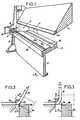
- Figure 1 en est une vue partielle en perspective;
- Figures 2 à 4 sont des vues schématiques en coupe transversale illustrant le mode de fonctionnement de cette presse plieuse;
- Figure 5 est une vue schématique illustrant une forme d'exécution des moyens de sécurité susceptibles d'équiper cette presse plieuse.
- Figure 1 is a partial perspective view;
- Figures 2 to 4 are schematic views in cross section illustrating the operating mode of this press brake;
- Figure 5 is a schematic view illustrating an embodiment of the security means capable of equipping this press brake.
La presse plieuse à tablier pivotant de l'invention comporte, comme les presses plieuses traditionnelles de ce type, une table horizontale fixe 2 disposée entre les deux montants latéraux 3 d'un bâti qui la supporte, entre lesquels est monté, de manière à pouvoir coulisser verticalement au-dessus de la table 2, un serre-tôle 4 guidé par des glissières verticales 5 aménagées sur les faces en regard des montants 3 du bâti. Ces derniers supportent en outre les tourillons 6, coaxiaux et d'axe horizontal commun 6a, de deux bras latéraux 7 supportant le tablier pivotant 8.The press brake with pivoting apron of the invention comprises, like traditional press brakes of this type, a fixed horizontal table 2 disposed between the two lateral uprights 3 of a frame which supports it, between which is mounted, so as to be able slide vertically above the table 2, a sheet clamp 4 guided by
La face active 8a de ce tablier 8, qui est celle encadrée par les deux bras latéraux 7, est normalement située dans le même plan horizontal que la face supérieure 2b de la table 2 lorsque le tablier 8 est en position de départ.The
Le fonctionnement de ce type de presse est le suivant :
- une tôle à plier, non représentée sur le dessin, ayant été préalablement posée sur la table 2 et la face active 8a du
tablier 8 de manière que la ligne le long de laquelle le pliage doit être réalisé coïncide avec l'arête supérieure 2a du bord antérieur de la table, le serre-tôle 4 est alors descendu pour presser cette tôle contre la table 2. Letablier 8 est ensuite pivoté dans le sens de la flèche 9, de telle sorte que sa face active 8a effectue le pliage de la tôle à plier autour du bord antérieur du serre-tôle 4. Cette face active 8a dutablier 8 est généralement constituée par un pièce 11 rapportée et fixée de manière amovible contre le bord correspondant dutablier 8a et apte à être remplacée en cas d'usure ou autre détérioration.
- a sheet to be folded, not shown in the drawing, having previously been placed on the table 2 and the
active face 8a of thedeck 8 so that the line along which the folding is to be carried out coincides with theupper edge 2a of the edge front of the table, the sheet clamp 4 is then lowered to press this sheet against the table 2. Thedeck 8 is then pivoted in the direction of the arrow 9, so that itsactive face 8a folds the sheet to be folded around the front edge of the sheet clamp 4. Thisactive face 8a of theapron 8 is generally constituted by an attached piece 11 and removably fixed against the corresponding edge of theapron 8a and capable of being replaced in the event of wear or other deterioration.
Comme cela ressort de l'examen de la figure 1, le bord antérieur 4a du serre-tôle 4 est lui aussi constitué par une pièce rapportée et interchangeable.As appears from the examination of Figure 1, the front edge 4a of the sheet clamp 4 is also constituted by an insert and interchangeable.
On conçoit aisément que la position des tourillons 6 dépend, d'une part, du rayon de courbure du pliage désiré et, d'autre part, de l'épaisseur de la tôle à plier et, pour cette raison, les tourillons 6 sont montés sur des coulisseaux 12 aptes à être déplacés en synchronisme et sur des courses rigoureusement égales.It is easy to see that the position of the pins 6 depends, on the one hand, on the radius of curvature of the desired folding and, on the other hand, on the thickness of the sheet to be folded and, for this reason, the pins 6 are mounted on sliders 12 capable of being moved in synchronism and on strictly equal strokes.
Pour permettre le réglage de la position des tourillons 6 en une seule opération au lieu de deux, comme cela est le cas dans les plieuses connues de ce type, la glissière de guidage 13 de chaque coulisseau 12 est disposée horizontalement de manière que l'axe commun 6a des tourillons 6 soit toujours situé dans le même plan horizontal que la face supérieure 2b de la table 2 et, par conséquent, que la face active 8a du tablier 8 lorsqu'il est en position de départ telle qu'illustrée sur la figure 1. En outre, le tablier 8 est fixé à ses bras supports latéraux 7 de manière que l'arête postérieure 8b de sa face active 8a, c'est-à-dire celle la plus proche de l'arête supérieure 2a du bord antérieur de la table 2 lorsqu'il est en position de départ comme illustrée sur la figure 1, soit confondue avec l'axe commun 6a des tourillons 6.To allow the position of the pins 6 to be adjusted in one operation instead of two, as is the case in known folding machines of this type, the guide slide 13 of each slide 12 is arranged horizontally so that the axis common 6a of the pins 6 is always located in the same horizontal plane as the upper face 2b of the table 2 and, consequently, that the
Chaque glissière 13 d'un coulisseau 12 est en outre disposée de manière que, dans l'une des positions extrêmes des coulisseaux 12, les arêtes 2a de la table 2 et 8b de la face active 8a du tablier 8 soient pratiquement confondues entre elles et avec l'axe commun 6a des tourillons 6, comme cela ressort de l'examen de la figure 1.Each slide 13 of a slide 12 is further arranged so that, in one of the extreme positions of the slides 12, the
Il en résulte que le fonctionnement de cette presse plieuse ne nécessite qu'une seule opération de réglage qui consiste à déplacer les coulisseaux 12 de manière à amener l'axe commun 6a des tourillons 6 dans la position imposée par la forme recherchée du pliage.It follows that the operation of this press brake requires only a single adjustment operation which consists in moving the sliders 12 so as to bring the common axis 6a of the pins 6 into the position imposed by the desired shape of the folding.
Si l'on appelle Ri le rayon de courbure antérieure de pliage de la tôle à plier 14 (figures 2 à 4), e l'épaisseur de la tôle 14 et a l'angle auquel doit être pliée la tôle 14, la distance X à laquelle doit être positionné l'axe commun 6a des tourillons 6 par rapport à l'arête antérieure 2a de la table 2 est donné par la formule suivante :
Les figures 2 à 4 illustrent trois opérations de pliage différentes d'une tôle 14 de même épaisseur, la course angulaire a du tablier pivotant 8 étant, respectivement, de 60°, 90° et 120°Figures 2 to 4 illustrate three operations of different bending of a
Comme on le voit nettement en examinant les figures 2 à 4, au cours d'une opération de pliage, le tablier 8 pivote autour de son arête postérieure 8b puisque cette dernière est constamment confondue avec l'axe commun 6a des tourillons 6.As can be clearly seen by examining FIGS. 2 to 4, during a folding operation, the
La figure 5 est une figure similaire aux figures 2 à 4 mais complétée par les moyens de réglage de la position du coulisseau 12 correspondant et ces moyens de réglage comportent un dispositif de sécurité décrit ci-après.Figure 5 is a figure similar to Figures 2 to 4 but supplemented by the means for adjusting the position of the corresponding slide 12 and these adjusting means comprise a safety device described below.
Chaque coulisseau 12 est lié axialement à une vis 15 engagée dans un écrou 16 solidaire du bâti 3.Each slide 12 is linked axially to a
On conçoit aisément qu'en manoeuvrant la vis 15 dans un sens ou dans l'autre, on déplace le coulisseau 12 qui lui est associé dans le même sens puisque l'écrou 16 est mobile tant en rotation qu'en translation. Lors d'une opération de pliage, la résistance au pliage de la tôle 14 exerce contre le tablier 8, et plus particulièrement contre la pièce 8a de ce dernier, une force de réaction entièrement supportée par les tourillons 6 et agissant dans le sens tendant à déplacer les coulisseaux 12 dans le sens correspondant à augmenter la distance X, c'est-à-dire dans le sens illustré par la flèche 17. Cette force est donc entièrement supportée par la vis 15 et l'écrou 16 et, si cette force dépasse la force maximale pour laquelle cette vis 15 et cet écrou 16 ont été calculés, il y a des risques de détérioration de ces deux organes.It is easy to see that by maneuvering the
Par mesure de sécurité, entre la face postérieure 16a de l'écrou 16 par laquelle il est en appui contre le bâti 3 et la face opposée 3a de ce dernier lui servant d'appui, est interposée une cale de sécurité 18.For safety reasons, a
Dans l'exemple illustré sur le dessin, cette cale de sécurité 18 est de forme annulaire et elle présente, sur chacune de ses faces latérales, une gorge d'affaiblissement également annulaire 19 la divisant en deux parties annulaires concentriques, l'une intérieure 18a et l'autre extérieure 18b.In the example illustrated in the drawing, this
Par ailleurs, le diamètre extérieur de l'écrou 16 est égal au diamètre dela gorge 19, tandis que la face d'appui du bâti 3 présente, en son centre, un évidement cylindrique 21 concentrique à la vis 15 et de diamètre intérieur égal au diamètre de la gorge 19 de la cale de sécurité 18.Furthermore, the external diameter of the
Cette disposition a pour effet que, dans le cas où la force agissant dans le sens de la flèche 17 sur la vis 15 et l'écrou 16 dépasse un seuil prédéterminé, les deux parties concentriques 18a et 18b de la cale de sécurité 18, sont séparées par cisaillage, ce qui autorise en recul de l'écrou 16 et de la vis 15 sur une course a égale à la longueur de l'évidement cylindrique 21. Cette course de recul de la vis 15 a l'effet immédiat de faire décroître considérablement la valeur de la force agissant dans le sens de la flèche 17 sur la vis 15 et d'éliminer par conséquent tout risque de rupture de la vis 15 et de l'écrou 16.This arrangement has the effect that, in the case where the force acting in the direction of the
Claims (2)

Priority Applications (1)
| Application Number | Priority Date | Filing Date | Title |
|---|---|---|---|
| AT87420097TATE51777T1 (en) | 1986-04-16 | 1987-04-13 | BENDING PRESS WITH SWING BEAM. |
Applications Claiming Priority (2)
| Application Number | Priority Date | Filing Date | Title |
|---|---|---|---|
| FR8605981 | 1986-04-16 | ||
| FR8605981AFR2597398B1 (en) | 1986-04-16 | 1986-04-16 | PIVOTING APRON BENDING PRESS |
Publications (2)
| Publication Number | Publication Date |
|---|---|
| EP0242309A1 EP0242309A1 (en) | 1987-10-21 |
| EP0242309B1true EP0242309B1 (en) | 1990-04-11 |
Family
ID=9334598
Family Applications (1)
| Application Number | Title | Priority Date | Filing Date |
|---|---|---|---|
| EP87420097AExpired - LifetimeEP0242309B1 (en) | 1986-04-16 | 1987-04-13 | Bending press with pivoting beam |
Country Status (7)
| Country | Link |
|---|---|
| US (1) | US4768367A (en) |
| EP (1) | EP0242309B1 (en) |
| AT (1) | ATE51777T1 (en) |
| DE (1) | DE3762190D1 (en) |
| ES (1) | ES2014033B3 (en) |
| FR (1) | FR2597398B1 (en) |
| GR (1) | GR3000433T3 (en) |
Cited By (1)
| Publication number | Priority date | Publication date | Assignee | Title |
|---|---|---|---|---|
| CN108714637A (en)* | 2018-03-29 | 2018-10-30 | 苏州赛腾精密电子股份有限公司 | A kind of folding material device suitable for automation equipment |
Families Citing this family (14)
| Publication number | Priority date | Publication date | Assignee | Title |
|---|---|---|---|---|
| DE3739173A1 (en)* | 1987-11-19 | 1989-06-01 | Feintool Int Holding | METHOD AND DEVICE FOR BENDING WORKPIECES |
| DE3935658A1 (en)* | 1989-10-26 | 1991-05-02 | Reinhardt Gmbh Maschbau | METHOD FOR TURNING A SHEET OPTIMALLY |
| US5259231A (en)* | 1989-10-26 | 1993-11-09 | Reinhardt Maschinenbau Gmbh | Process for the two-directional bending of sheet metal |
| DE3935659C3 (en)* | 1989-10-26 | 1997-01-02 | Reinhardt Gmbh Maschbau | Device for bending a sheet |
| FR2667520A1 (en)* | 1990-10-05 | 1992-04-10 | Guillaume Bernard | Bending press having a table (board) articulated by means of a hinge |
| DE19523226A1 (en)* | 1995-06-27 | 1995-12-14 | Joachim Linde | System for bending sheet metal |
| DE19844244A1 (en)* | 1998-09-26 | 2000-03-30 | Fastenrath Fasti Werk | Device for bending sheet metal |
| DE10245777A1 (en)* | 2002-09-26 | 2004-04-08 | Reinhardt Maschinenbau Gmbh | A bending machine for metal sheets has an interchangeable bending tool mounted on a number of wedge blocks by which fine adjustment may be made |
| US7228721B2 (en)* | 2003-01-17 | 2007-06-12 | Tapco International Corporation | Pivot link for sheet bending brake and sheet bending brake including pivot link |
| CA2468381C (en)* | 2003-06-10 | 2007-12-04 | Perry Mcadam | Tool kit and method for working sheet metal trims |
| DE102006003500B3 (en)* | 2006-01-24 | 2007-08-16 | Ralf Beger | Blechabkantvorrichtung |
| DE102008064227B3 (en)* | 2008-12-22 | 2010-05-27 | Ralf Beger | A method for folding a sheet metal part in a Blechabkantvorrichtung and suitable for performing this method Blechabkantvorrichtung for folding a sheet metal part |
| CN106001195B (en)* | 2016-05-25 | 2018-05-29 | 广西田阳至恒门业有限公司 | Bender |
| DE102018000971B3 (en) | 2018-02-02 | 2019-03-07 | Gustav-Adolf Hochstrate | Swivel bending machine with adjustment of the swivel axis of the bending beam |
Family Cites Families (9)
| Publication number | Priority date | Publication date | Assignee | Title |
|---|---|---|---|---|
| CA469946A (en)* | 1950-12-12 | Anderson Frohman | Apparatus and methods for working sheet metal | |
| DE303138C (en)* | ||||
| US1194602A (en)* | 1916-08-15 | Mechanism | ||
| DE584362C (en)* | 1933-09-19 | Hiltmann & Lorenz Akt Ges Masc | Bending beam for folding machines | |
| FR1040494A (en)* | 1951-08-10 | 1953-10-15 | Bending machine for sheet metal and similar material | |
| GB951895A (en)* | 1962-01-30 | 1964-03-11 | Oliver Machinery Co | Improvements relating to folder brakes for forming corners in sheet material |
| FR1454083A (en)* | 1965-10-22 | 1966-07-22 | Plamag Plauener Druckmaschinen | Device for bending clichés and printing plates |
| FR2502518A1 (en)* | 1981-03-26 | 1982-10-01 | Favrin Pierre | Folding press for return bends in sheet metal - has folding plate pivoting in two planes against bolster |
| FR2509204A1 (en)* | 1981-07-07 | 1983-01-14 | Jouanel Sa Ets Y | AUTOMATIC SHEET BENDER |
- 1986
- 1986-04-16FRFR8605981Apatent/FR2597398B1/ennot_activeExpired - Lifetime
- 1987
- 1987-04-13ATAT87420097Tpatent/ATE51777T1/enactive
- 1987-04-13ESES87420097Tpatent/ES2014033B3/ennot_activeExpired - Lifetime
- 1987-04-13DEDE8787420097Tpatent/DE3762190D1/ennot_activeExpired - Lifetime
- 1987-04-13EPEP87420097Apatent/EP0242309B1/ennot_activeExpired - Lifetime
- 1987-04-16USUS07/039,607patent/US4768367A/ennot_activeExpired - Lifetime
- 1990
- 1990-04-12GRGR90400149Tpatent/GR3000433T3/enunknown
Cited By (2)
| Publication number | Priority date | Publication date | Assignee | Title |
|---|---|---|---|---|
| CN108714637A (en)* | 2018-03-29 | 2018-10-30 | 苏州赛腾精密电子股份有限公司 | A kind of folding material device suitable for automation equipment |
| CN108714637B (en)* | 2018-03-29 | 2019-11-19 | 苏州赛腾精密电子股份有限公司 | A kind of folding material device suitable for automation equipment |
Also Published As
| Publication number | Publication date |
|---|---|
| ATE51777T1 (en) | 1990-04-15 |
| FR2597398A1 (en) | 1987-10-23 |
| DE3762190D1 (en) | 1990-05-17 |
| GR3000433T3 (en) | 1991-06-28 |
| FR2597398B1 (en) | 1990-12-07 |
| EP0242309A1 (en) | 1987-10-21 |
| ES2014033B3 (en) | 1990-06-16 |
| US4768367A (en) | 1988-09-06 |
Similar Documents
| Publication | Publication Date | Title |
|---|---|---|
| EP0242309B1 (en) | Bending press with pivoting beam | |
| FR2530980A1 (en) | BENDER WITH MULTIPLE CURVES | |
| EP0089904B1 (en) | Flat bending device | |
| FR2467041A1 (en) | DEBURRING APPARATUS FOR CONTINUOUS CASTING BRUSHES | |
| FR2509204A1 (en) | AUTOMATIC SHEET BENDER | |
| EP0686450B1 (en) | Cutting apparatus for profiled material e.g. gutters | |
| EP1264647B1 (en) | Press brake for sheets with a movable workpiece stop device | |
| EP0463952A1 (en) | Method for sharpening the blades of a rotary drum and adjusting the fixed counter-cutter cooperating with them, and device for carrying out this method | |
| FR2567429A1 (en) | MACHINE FOR BENDING TUBES, BARS OR PROFILES | |
| EP2756923A1 (en) | Clamp meter, in particular for an earth loop, including a jaw secured to a stationary mounting and a jaw pivotably mounted on the mounting | |
| WO2000005086A1 (en) | Device for fixing a joint on a motor vehicle body and method using same | |
| EP0734338A1 (en) | Mounting of one wheel of a motorcycle on a stand and test stand therefor provided with roller | |
| FR2746050A1 (en) | DEVICE FOR LONGITUDINAL CUTTING OF A TUBE | |
| EP1690619B1 (en) | Cutting table for metal sheets | |
| EP0281488A1 (en) | Turning bending head for a tube-bending machine | |
| FR2483269A1 (en) | Reel unwinding starter and guide - has starting head passing under reel end actuated by hydraulic jack mounted on frame | |
| BE1006875A5 (en) | Mechanism exchanger stylus in machine automatic draw. | |
| FR2642691A1 (en) | Apparatus intended to be fixed to a wrist of a robot for fitting a door seal | |
| FR2708491A1 (en) | Device for preassembling two pieces to be crimped together | |
| FR2686533A1 (en) | Bending press (press-brake) with a bed, for safe operation | |
| FR2606965A1 (en) | FILM RETAINING DEVICE FOR ROLLER MACHINE AND SEEDER | |
| EP2871006B1 (en) | Folder for flat blank | |
| EP0320408B1 (en) | Control device for the reglet of a tube-bending machine | |
| EP0619151A1 (en) | Apparatus for manipulating a piece during successive bending operations of that piece in a press | |
| FR2774011A1 (en) | Machine for crimping sheet metal joints in motor vehicle industry |
Legal Events
| Date | Code | Title | Description |
|---|---|---|---|
| PUAI | Public reference made under article 153(3) epc to a published international application that has entered the european phase | Free format text:ORIGINAL CODE: 0009012 | |
| 17P | Request for examination filed | Effective date:19870812 | |
| AK | Designated contracting states | Kind code of ref document:A1 Designated state(s):AT BE CH DE ES GB GR IT LI LU NL SE | |
| 17Q | First examination report despatched | Effective date:19890110 | |
| GRAA | (expected) grant | Free format text:ORIGINAL CODE: 0009210 | |
| AK | Designated contracting states | Kind code of ref document:B1 Designated state(s):AT BE CH DE ES GB GR IT LI LU NL SE | |
| REF | Corresponds to: | Ref document number:51777 Country of ref document:AT Date of ref document:19900415 Kind code of ref document:T | |
| ITF | It: translation for a ep patent filed | ||
| GBT | Gb: translation of ep patent filed (gb section 77(6)(a)/1977) | ||
| REF | Corresponds to: | Ref document number:3762190 Country of ref document:DE Date of ref document:19900517 | |
| REG | Reference to a national code | Ref country code:GR Ref legal event code:FG4A Free format text:3000433 | |
| PLBE | No opposition filed within time limit | Free format text:ORIGINAL CODE: 0009261 | |
| STAA | Information on the status of an ep patent application or granted ep patent | Free format text:STATUS: NO OPPOSITION FILED WITHIN TIME LIMIT | |
| PGFP | Annual fee paid to national office [announced via postgrant information from national office to epo] | Ref country code:GR Payment date:19910308 Year of fee payment:5 | |
| 26N | No opposition filed | ||
| PGFP | Annual fee paid to national office [announced via postgrant information from national office to epo] | Ref country code:LU Payment date:19920227 Year of fee payment:6 | |
| PGFP | Annual fee paid to national office [announced via postgrant information from national office to epo] | Ref country code:CH Payment date:19920302 Year of fee payment:6 | |
| PGFP | Annual fee paid to national office [announced via postgrant information from national office to epo] | Ref country code:SE Payment date:19920304 Year of fee payment:6 | |
| ITTA | It: last paid annual fee | ||
| EPTA | Lu: last paid annual fee | ||
| PG25 | Lapsed in a contracting state [announced via postgrant information from national office to epo] | Ref country code:GR Free format text:THE PATENT HAS BEEN ANNULLED BY A DECISION OF A NATIONAL AUTHORITY Effective date:19921031 | |
| PG25 | Lapsed in a contracting state [announced via postgrant information from national office to epo] | Ref country code:LU Free format text:LAPSE BECAUSE OF NON-PAYMENT OF DUE FEES Effective date:19930413 | |
| PG25 | Lapsed in a contracting state [announced via postgrant information from national office to epo] | Ref country code:SE Effective date:19930414 | |
| PG25 | Lapsed in a contracting state [announced via postgrant information from national office to epo] | Ref country code:LI Effective date:19930430 Ref country code:CH Effective date:19930430 | |
| REG | Reference to a national code | Ref country code:CH Ref legal event code:PL | |
| PGFP | Annual fee paid to national office [announced via postgrant information from national office to epo] | Ref country code:AT Payment date:19940429 Year of fee payment:8 | |
| REG | Reference to a national code | Ref country code:GR Ref legal event code:MM2A Free format text:3000433 | |
| EUG | Se: european patent has lapsed | Ref document number:87420097.5 Effective date:19931110 | |
| PG25 | Lapsed in a contracting state [announced via postgrant information from national office to epo] | Ref country code:AT Effective date:19950413 | |
| PGFP | Annual fee paid to national office [announced via postgrant information from national office to epo] | Ref country code:GB Payment date:19960404 Year of fee payment:10 | |
| PGFP | Annual fee paid to national office [announced via postgrant information from national office to epo] | Ref country code:NL Payment date:19960430 Year of fee payment:10 | |
| PG25 | Lapsed in a contracting state [announced via postgrant information from national office to epo] | Ref country code:GB Effective date:19970413 | |
| PG25 | Lapsed in a contracting state [announced via postgrant information from national office to epo] | Ref country code:NL Effective date:19971101 | |
| GBPC | Gb: european patent ceased through non-payment of renewal fee | Effective date:19970413 | |
| NLV4 | Nl: lapsed or anulled due to non-payment of the annual fee | Effective date:19971101 | |
| PGFP | Annual fee paid to national office [announced via postgrant information from national office to epo] | Ref country code:ES Payment date:19990419 Year of fee payment:13 | |
| PG25 | Lapsed in a contracting state [announced via postgrant information from national office to epo] | Ref country code:ES Free format text:THE PATENT HAS BEEN ANNULLED BY A DECISION OF A NATIONAL AUTHORITY Effective date:20000414 | |
| REG | Reference to a national code | Ref country code:ES Ref legal event code:FD2A Effective date:20020204 | |
| PGFP | Annual fee paid to national office [announced via postgrant information from national office to epo] | Ref country code:BE Payment date:20040428 Year of fee payment:18 | |
| PGFP | Annual fee paid to national office [announced via postgrant information from national office to epo] | Ref country code:DE Payment date:20040430 Year of fee payment:18 | |
| PG25 | Lapsed in a contracting state [announced via postgrant information from national office to epo] | Ref country code:IT Free format text:LAPSE BECAUSE OF NON-PAYMENT OF DUE FEES;WARNING: LAPSES OF ITALIAN PATENTS WITH EFFECTIVE DATE BEFORE 2007 MAY HAVE OCCURRED AT ANY TIME BEFORE 2007. THE CORRECT EFFECTIVE DATE MAY BE DIFFERENT FROM THE ONE RECORDED. Effective date:20050413 | |
| PG25 | Lapsed in a contracting state [announced via postgrant information from national office to epo] | Ref country code:BE Free format text:LAPSE BECAUSE OF NON-PAYMENT OF DUE FEES Effective date:20050430 | |
| BERE | Be: lapsed | Owner name:*FAVRIN PIERRE Effective date:20050430 | |
| PG25 | Lapsed in a contracting state [announced via postgrant information from national office to epo] | Ref country code:DE Free format text:LAPSE BECAUSE OF NON-PAYMENT OF DUE FEES Effective date:20051101 | |
| BERE | Be: lapsed | Owner name:*FAVRIN PIERRE Effective date:20050430 |