EP0241105B1 - Electronically programmable universal brushless dc fan with integral tracking and locked rotor protection - Google Patents
Electronically programmable universal brushless dc fan with integral tracking and locked rotor protectionDownload PDFInfo
- Publication number
- EP0241105B1 EP0241105B1EP87300371AEP87300371AEP0241105B1EP 0241105 B1EP0241105 B1EP 0241105B1EP 87300371 AEP87300371 AEP 87300371AEP 87300371 AEP87300371 AEP 87300371AEP 0241105 B1EP0241105 B1EP 0241105B1
- Authority
- EP
- European Patent Office
- Prior art keywords
- fan
- voltage
- windings
- circuit
- regulator
- Prior art date
- Legal status (The legal status is an assumption and is not a legal conclusion. Google has not performed a legal analysis and makes no representation as to the accuracy of the status listed.)
- Expired - Lifetime
Links
- 238000004804windingMethods0.000claimsabstractdescription121
- 230000000670limiting effectEffects0.000claimsabstractdescription16
- 238000001816coolingMethods0.000claimsdescription10
- 239000004020conductorSubstances0.000claimsdescription9
- 238000000034methodMethods0.000claimsdescription3
- 238000004519manufacturing processMethods0.000abstractdescription11
- 230000001681protective effectEffects0.000abstractdescription3
- 230000004075alterationEffects0.000abstract1
- 230000008901benefitEffects0.000description4
- 230000033228biological regulationEffects0.000description4
- 230000001276controlling effectEffects0.000description4
- 238000007792additionMethods0.000description3
- 230000000694effectsEffects0.000description3
- 239000003990capacitorSubstances0.000description2
- 230000015556catabolic processEffects0.000description2
- 230000008859changeEffects0.000description2
- 230000009467reductionEffects0.000description2
- 241000239290AraneaeSpecies0.000description1
- 229910000831SteelInorganic materials0.000description1
- 230000002411adverseEffects0.000description1
- 230000003466anti-cipated effectEffects0.000description1
- 230000003247decreasing effectEffects0.000description1
- 230000001419dependent effectEffects0.000description1
- 238000010586diagramMethods0.000description1
- 230000008030eliminationEffects0.000description1
- 238000003379elimination reactionMethods0.000description1
- 230000004048modificationEffects0.000description1
- 238000012986modificationMethods0.000description1
- 230000002829reductive effectEffects0.000description1
- 230000001105regulatory effectEffects0.000description1
- 230000004044responseEffects0.000description1
- 239000010959steelSubstances0.000description1
Images

Classifications
- H—ELECTRICITY
- H02—GENERATION; CONVERSION OR DISTRIBUTION OF ELECTRIC POWER
- H02P—CONTROL OR REGULATION OF ELECTRIC MOTORS, ELECTRIC GENERATORS OR DYNAMO-ELECTRIC CONVERTERS; CONTROLLING TRANSFORMERS, REACTORS OR CHOKE COILS
- H02P6/00—Arrangements for controlling synchronous motors or other dynamo-electric motors using electronic commutation dependent on the rotor position; Electronic commutators therefor
- H02P6/08—Arrangements for controlling the speed or torque of a single motor
- H—ELECTRICITY
- H02—GENERATION; CONVERSION OR DISTRIBUTION OF ELECTRIC POWER
- H02H—EMERGENCY PROTECTIVE CIRCUIT ARRANGEMENTS
- H02H7/00—Emergency protective circuit arrangements specially adapted for specific types of electric machines or apparatus or for sectionalised protection of cable or line systems, and effecting automatic switching in the event of an undesired change from normal working conditions
- H02H7/08—Emergency protective circuit arrangements specially adapted for specific types of electric machines or apparatus or for sectionalised protection of cable or line systems, and effecting automatic switching in the event of an undesired change from normal working conditions for dynamo-electric motors
- H02H7/0811—Emergency protective circuit arrangements specially adapted for specific types of electric machines or apparatus or for sectionalised protection of cable or line systems, and effecting automatic switching in the event of an undesired change from normal working conditions for dynamo-electric motors for DC motors
Definitions
- This inventionrelates to brushless DC fans, which is to say fans driven by brushless DC motors, and more particularly to such fans that have a circuit permitting operation of the fan over a range of voltages, allowing fan speed and air delivery to be programmed, making available temperature tracking limiting current, and affording locked rotor protection.
- a fan of a given sizemay have more than one operating voltage. That is, a given fan size may be available in both 12 and 24 volt models.
- a given fan sizemay be available in both 12 and 24 volt models.
- different air flow requirementscan dictate the use of different motor windings, electronics, and protection circuitry.
- These differing fan characteristics among fans that appear identical in size, housing layout, venturi, and impellerraise difficulties in manufacturing control and add cost as compared to the production of a single fan model with consistent windings and circuitry.
- fan customersinventory several different model fans to meet the varied requirements among their varied products.
- PTCpositive temperature coefficient
- the thermistorwas supported in close proximity to the stator on a circuit board.
- the circuit boardin addition, supported the commutation sensing device that controlled stator winding energization and the stator winding energization circuit that directed flow of direct current to the windings under control of the commutation sensing device.
- the increased temperature that arose with a locked rotorcaused the thermistor resistance to increase significantly and reduce the current to the particular stator winding when, in the locked rotor condition, the impeller was immobilized.
- an equipment cooling fancomprising a brushless DC motor, the motor having a permanent magnet rotor, a centrally mounted stator wound with windings, a winding supply circuit centrally mounted with the stator, and a commutation and switching circuit centrally mounted with the stator and the winding supply circuit, the ends of the windings being electrically connected to the winding supply circuit, the winding supply circuit having thermal protection mounted internally, the rotor being located in an impeller having blades supported thereon radially outward from the rotor, and voltage setting means connected to said winding supply circuit to set the output voltage thereof and establish a desired fan speed, characterised in that the winding supply circuit includes a voltage regulator, having said winding supply circuit thermal protection incorporated therein, and being connected in output voltage relation to said voltage setting means and in current conducting relation to the windings, the winding supply circuit having means connected between the voltage regulator and the windings to provide, in cooperation with the voltage regulator, current limiting of the current to the wind
- the regulatoris a commercially available integrated circuit (IC).
- the regulatormay provide thermal protection adequate to protect the fan motor in a locked rotor condition. However this is not essential.
- a second aspect of the present inventionprovides an equipment cooling fan comprising a brushless DC motor, the motor having a permanent magnet rotor, a centrally mounted stator wound with windings, a winding supply circuit centrally mounted with the stator, and a commutation and switching circuit centrally mounted with the stator and the winding supply circuit, the ends of the windings being electrically connected to the winding supply circuit, the rotor being located in an impeller having blades supported thereon radially outward from the rotor, said winding supply circuit having an output voltage controlling connection for establishing the output voltage across the windings whereby the winding supply circuit and a preselected circuit element connected externally of the fan to said circuit connection set the fan speed; characterised in that the winding supply circuit includes a voltage regulator connected in output voltage relation to said pre-selected circuit element and in
- the regulator ICcan be introduced without greatly increasing the cost of the brushless DC fan.
- the voltage regulator and its related voltage divider elementsare added to the internal PC board, but they replace a positive temperature coefficient thermistor, and therefore the parts cost increase is small. Other less apparent savings are afforded by this change in internal circuitry. These further significantly reduce the cost of adding the voltage regulator and associated circuit elements. Ultimately, a manufacturing cost saving should result from the winding supply circuit additions.
- just one basic set of stator windings and standard circuit for a particular fan size and voltage ratingcan replace the variations that were previously provided for the purpose of offering fans of various rated voltages and speed in a given fan size.
- the present inventionin a fan of a particular size and input voltage, there is no longer a need to wind a stator differently for different speeds.
- the production linewas stopped while winders were changed over to a different number of turns of different size wire. Elimination of these stoppages increases efficiency and reduces cost.
- the windings that previously called for the fewest turns of the heaviest wireare now wound on every stator of the motor of a particular fan size.
- this winding supply circuitdetermines fan speed permits, for a fan of a particular input voltage, a speed not previously possible by choice of windings, because insufficient space existed to wind the stator with the requisite turns of appropriately sized wire.
- the winding supply circuit's IC voltage regulatorwhich is like that previously suggested for use externally of a fan as a supply in addition to all of the fan's internal circuitry, may have an adjust terminal that enables its output voltage to be chosen based on the voltage at the adjust terminal. Selection of a resistor or a Zener diode for connection between the adjust terminal and ground will determine the regulator's output voltage, the voltage applied to the fan motor's stator windings and, therefore, the fan speed.
- the winding supply circuitmay use a resistor in series between the regulator and the stator windings for current limiting. If excessive current is drawn, as occurs during fan motor start up or in the event of a locked rotor, then the voltage across the resistor is used to reduce the output voltage of the voltage regulator. When locked rotor occurs, the voltage reduction is so great as to effect a maximum voltage drop from the input to the output of the regulator and in the case where the regulator is provided with thermal protection, this causes the regulator's thermal protection to shut down the regulator.
- a single lead from the adjust terminal of the voltage regulatormay be brought to the exterior of the fan housing, to permit the user's control of the fan in the many ways mentioned above, by connection of the speed setting resistor, or the speed varying thermistor, or the control provisions. If, for example, the fan is to be run at low speed or not at all during a stand-by condition of the equipment to be cooled, a low resistance applied between the external adjust terminal lead and ground will accomplish that. Where fans cool microprocessor based circuitry or other digital circuitry, programmed resistance can increase or decrease the winding voltage of the winding supply circuit to increase or decrease fan speed as needed.
- a digital to analog convertercan be used and speed can be tailored to the equipment's anticipated cooling needs. Even the use of a single resistor to set a fixed fan speed permits the fan user to select less than the highest available speed if adequate. Noise and power consumption are then reduced commensurately.
- An internal resistor or Zener diode connected to the internally housed voltage regulator ICcan be used by the fan manufacturer to set the maximum fan speed at which the fan will operate, should the purchaser choose not to tailor its operation.
- the manufacturercan choose a resistance to set the voltage drop across the current limiting resistor used to drop the voltage adjust terminal voltage that sets the regulator's output voltage. In this way the maximum current can be chosen
- the winding supply circuitry with its regulator ICis mounted on the fan motor printed circuit board, internally of the fan housing, no cumbersome external circuitry accompanies the fan to limit current and set speed.
- the regulatorprovides constant fan speed in the face of varying input voltages by virtue of the regulated voltage supplied to the windings.
- fans of any kindare used to cool electronics
- the electronics manufacturertypically prefers the fan that is least noticeable. That is to say, the fan that generates the least noise, occupies the least space, and consumes the least power, while providing the needed cooling, is the fan that is most attractive to the electronics manufacturer. If a fan of the exact speed is not available, then an electronics manufacturer must use a fan with an air flow rated above the minimum needed to assure adequate cooling, but if that same fan can be tailored to the manufacturer's exact speed requirement, than less power can be consumed and less noise can be generated.
- a brushless DC fan 10includes a housing 11 with a front surface 12, a rear surface 13, and a venturi 14 extending between the front and rear surfaces.
- the motor, generally designated 15,is centrally located. Its stator and circuit are supported in fixed relation to the housing 12 in a central housing portion 16 connected to the venturi by struts 17 of a spider structure. Leads 19, 20 and 21 are brought out from the motor electronics along one strut 17' specially formed for this purpose with a longitudinal channel leading to a narrow groove 23 at the outer periphery of the motor housing 12. The groove retains the leads in the channel while directing them toward the generally cylindrical exterior 25 of the housing 11 as shown.
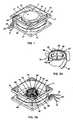
- Figures 2a and 2bshow the rotational and stationary parts of the fan of Figure 1 separated.
- Figure 2bshows the housing 11, a stator 28, and circuitry 29 of the fan 10 of Figure 1, inverted from their Figure 1 position.
- Figure 2aillustrates the impeller 30 of the fan 10 of Figure 1.
- the impellerincludes fan blades 31 supported on a hub 32, for example of plastic, in turn secured to the rotor 35 of the fan's motor.
- the rotor 35has an annular permanent magnet 37 in a steel cup 38.
- a central shaft 39 secured to the end face of the cup 38is received in bearings 41 in the stator assembly of Figure 2b when the fan 10 is assembled.
- the fan circuitry 29is mounted on a circular printed circuit board 43.
- a Hall sensor 45is supported on the PC board 43 where it will be located inside the magnet 37, just opposite a commutation portion of that magnet used to control switching of current to windings 47 on the stator as described, for example, in the applicant's earlier U.S. Patent No. 4,494,028.
- This, in Figure 2ais the portion of the magnet 37 nearest the open end of the cup.
- a field magnet portion of the magnet 37interacts with poles 49 of the stator to effect rotation of the impeller upon proper commutation of the energizing current to the windings 47 of the stator.
- Leads 19 and 20supply the electrical power that activates the circuit 29 and energizes the windings 47.
- the lead 21is used to tailor the operation of the fan to the end user's particular needs in the manner of this invention as described below in greater detail.
- the leads 19 and 20supply the fan circuit 29 with supply voltage v s .
- the fan circuit 29comprises a winding supply circuit 49 and a switching circuit 50.
- the lead 19supplies the high side or positive v s supply voltage via a protective diode 51 to both circuits.
- v sis supplied to the input of a voltage regulator IC 53 that is on the PC board 43 of Figure 2b.
- the regulator 53can be a commercially available integrated circuit such as the LM317 available from Motorola.
- the winding supply circuit of Figure 3affords both voltage and current regulation.
- the regulator ICis a three terminal device that has, in addition to its input terminal 54, an output terminal 55, and an adjust terminal 56.
- a Zener diode 58establishes the maximum voltage at the adjust terminal 56.
- the voltage at the adjust terminal 56sets the ouput voltage of the regulator 53 at the output terminal 55.
- the integrated circuit voltage regulator 53With an appropriate input voltage applied and an appropriate resistor 59 connected between the regulator's adjust and output terminals, 56 and 55, the integrated circuit voltage regulator 53 has an output voltage about 1.25 volts higher than the voltage at the adjust terminal 56.
- the total IC output voltage V outwhich is measured from the output terminal 55 to the ground or negative line 20, is the sum of this voltage and the voltage drop across a Zener diode 58.
- a resistor 61 and a diode 62serve the current limiting purposes of the winding supply circuit.
- the voltage drop across the resistor 61is proportional to the current being drawn by the stator windings.
- the drop across the resistor 61becomes sufficient for the diode 62 to begin to conduct, referencing the voltage at the adjust terminal 56 to the decreased voltage at the junction of the resistor 61 and the windings 47.
- the decrease in voltage at the adjust terminal 56reduces the output voltage from the regulator IC, limiting the current to the windings.
- a programming element or means 63such as the external resistor 64 is connected between the external lead 21 provided for that purpose and the external lead 20.
- the external resistor 64can be applied by the fan purchaser.
- the voltage V out at the outputis then 1.25 volts above the voltage V adj. at the adjust terminal 56 as established by the resistors 59 and 64 acting as a voltage divider and establishing a V adj. below the Zener voltage or breakdown voltage of the Zener diode 58.
- the speed of the brushless DC motoris controlled by the voltage regulator 53 and its programming element 63.
- the programming element 63can be a positive temperature coefficient thermistor wired into the energization circuit by the leads 21 and 20.
- the thermistorcan be alone or in conjunction with a speed setting resistor 64.
- the thermistorcan be located where temperature increases or is most critical, so that an increase in its temperature raises the voltage V out and increases fan speed until the temperature returns to a lower value.
- the fan usercan choose a more elaborate manner of fan speed control if desired. Where, for example, the fan is used to cool digital electronics and microprocessor control is available, then the fan programming element 63 can be microprocessor controlled resistance of the nature of a digital to analog converter.
- the fan usermight choose to turn the fan off or operate it at a minimum speed during an inoperative or standby condition of the equipment being cooled.
- Various fan speedscan be tailored to various operations of the equipment being cooled based on the programming of the microprocessor. Only the needed air flow would be provided for any particular operation, and higher power demands and noise generation would often be avoided. It will be clear that the various ways of programming this fan saves the end user power that he would rather not use or would rather dedicate to the electronics being cooled by the fan, which the electronics are, in his view, the primary product.
- Zener diode 58permits the output voltage setting resistors 59 and 64 to establish the voltage at the adjust terminal 56 independently of the Zener diode. These resistors reduce V adj. below the Zener voltage. Because the Zener diode's effect is not apparent to the user, the choice of resistance of the resistor 64 is simplified. The resistance can be chosen as though it is the only element connected between the adjust terminal and ground and the regulator IC behaves in just that way, the regulator output increasing with increasing resistance of the resistor 64.
- the maximum fan speed setting element connected between the adjust terminal and ground internally of the fancould, alternatively, be a resistor rather than the Zener diode 58, but the resistance from the adjust terminal to ground, when a speed setting external resistance 64 is connected, would be the combined resistance of the parallel resistors and less easily determined to select fan speed.
- V outWhen the fan is to be the highest speed fan model of a series of fans of a particular input voltage, the highest V out from the regulator 53 is desired. V out will then be V s less the small drop, about 1.4 volts, across the IC.
- the Zener diodecan be omitted.
- the V outcan be programmed by the fan user by connection of a programming element 63 just as with the fan of Figure 3.
- a resistor 65shown in broken lines in Figure 3 is connected, internally, in series between the adjust terminal 56 and the externally accessible end of the programming lead 21. This prevents the user from connecting the adjust terminal 56 directly to ground or + supply via the lead 21.
- An exemplary brushless DC fan with the circuit of Figure 3had a four pole brushless DC motor wound with 190 turns of #27 wire in each of the two windings 47 to give a 7 ⁇ resistance for each.
- the pertinent circuit element values, and component identificationwere as follows: Zener diode 58 1N5246 (16V Zener voltage) Resistor 59 1K ⁇ Resistor 61 .91 ⁇ Diode 62 1N4148 Transistors 73 & 74 TIP102 (National) Capacitors 78 & 79 .01 ⁇ f. Fan speed and relevant voltages responded to external resistance, resistor 64, as follows: V s R64 Zener V Adj.
- Thermal protectionmay be afforded by the regulator IC 53 as well.
- the IC 53provides thermal protection regardless of the speed set by the speed programming components connected to the adjust terminal 56. Too great a voltage drop across the IC 53, from its input terminal 54 to its output terminal 55, initiates its thermal protection.
- the excessive current through the current limiting resistor 61greatly reduces the output voltage from the regulator. For a fan of a given input voltage, in a locked rotor condition, regardless of programmed output voltage and speed, excessive voltage drop across the IC will occur and cause the IC to stop conducting.
- the switching circuit 50As for the switching circuit 50, it is supplied with power from the line 19 via the protective diode 51 and a current limiting resistor 67. A capacitor 69 can be connected across the circuit 50's input to suppress transients if desired.
- a separate internally housed voltage regulator 70supplies a commutation circuit that includes the Hall sensor 45 of Figure 2b. The commutation circuit 71 alternately energizes the windings 47 by switching a pair of transistors 73 and 74 into conduction by application of its alternate outputs 76 and 77 as base drives. Each of the transistors 73 and 74 can be a prepackaged Darlington pair as shown.
- the voltage regulator 53controls the voltage applied across the windings 47, but does not affect the voltage applied to the commutation circuit 71. So the IC 53 can be freely programmed to control fan speed without concern for adversely affecting the operation of the switching circuit.
- V outWhen the appropriate output voltage V out is substantially less than the supply voltage V s the regulator 53 supplies a constant V out to keep fan speed constant despite variations that may occur in V s provided that these variations do not bring V s near the chosen V out .
- V sthe supply voltage
Landscapes
- Engineering & Computer Science (AREA)
- Power Engineering (AREA)
- Control Of Motors That Do Not Use Commutators (AREA)
- Control Of Electric Motors In General (AREA)
- Control Of Positive-Displacement Air Blowers (AREA)
- Structures Of Non-Positive Displacement Pumps (AREA)
- Connection Of Motors, Electrical Generators, Mechanical Devices, And The Like (AREA)
Abstract
Description
- This invention relates to brushless DC fans, which is to say fans driven by brushless DC motors, and more particularly to such fans that have a circuit permitting operation of the fan over a range of voltages, allowing fan speed and air delivery to be programmed, making available temperature tracking limiting current, and affording locked rotor protection.
- Brushless DC fans are increasingly popular for such applications as cooling electronics. A fan of a given size may have more than one operating voltage. That is, a given fan size may be available in both 12 and 24 volt models. For a particular fan size of a particular operating voltage, different air flow requirements can dictate the use of different motor windings, electronics, and protection circuitry. These differing fan characteristics among fans that appear identical in size, housing layout, venturi, and impeller raise difficulties in manufacturing control and add cost as compared to the production of a single fan model with consistent windings and circuitry. Frequently, fan customers inventory several different model fans to meet the varied requirements among their varied products. Considerable simplification of manufacturing by the fan maker, and of ordering and stocking by the customer could be effected if a single standardized brushless DC fan could be provided for a particular desired fan size and input voltage and if a means of programming that fan's operating characteristics could be utilized to simply set the operational characteristics of the fan for its particular rated voltage without winding changes and without extensive circuit modifications. This also would have the benefit of enabling the manufacturer to respond quickly to customer orders either from inventories or by rapidly increasing current production without time-consuming production line changes.
- In past brushless DC fans, locked rotor protection was afforded by a positive temperature coefficient (PTC) thermistor that was in series between the windings and the input connections to the fan. The thermistor was supported in close proximity to the stator on a circuit board. The circuit board, in addition, supported the commutation sensing device that controlled stator winding energization and the stator winding energization circuit that directed flow of direct current to the windings under control of the commutation sensing device. The increased temperature that arose with a locked rotor caused the thermistor resistance to increase significantly and reduce the current to the particular stator winding when, in the locked rotor condition, the impeller was immobilized.
- For the purpose of limiting current to a fan during start up, or in a locked rotor condition, or for varying the voltage applied to a brushless DC fan, the inventor has, in the past, suggested an external voltage regulator. But both fan current limiting and voltage regulation by one voltage regulator were not suggested, particularly by internal fan circuitry. An integrated circuit like the Motorola LM117, LM217 or LM317 was suggested for use as a power supply for fans for cooling electronics. This circuit is a three-terminal device that has an output voltage dependent on a voltage established at an "adjust" terminal thereof. Fan customers, it was suggested, could choose a value of resistance between that terminal and ground to provide the desired air flow for cooling. The use of a thermistor as the resistance element connected to the adjust terminal of such a separate regulation circuit could be used to monitor temperature and adjust fan speed based on the monitored temperature.
- In brushless DC motors it has long been recognised that the need for a commutation and energization circuit that controlled energization of the stator windings was a commercial impediment by virtue of its increasing the cost of these motors vis-a-vis AC motors or brush-type DC motors that require no such circuitry. This has been true of brushless DC fans. For example, US Patent 4,554,491 discloses a brushless DC motor having a laminated stator with a single stator winding. An external control circuit is provided to modify the motor speed in accordance with the output of a thermal sensor by using the output to modulate the duty cycle of a rectangular waveform. There has been, therefore, a continuing effort to minimize the cost of such circuitry such that fewer and less expensive circuit components have been chosen to reduce the overall cost of brushless DC fans. Moreover, competition for brushless DC fans has been primarily price competition, and this too has led away from additions to the internal fan circuitry.
- According to a first aspect of the invention there is provided an equipment cooling fan comprising a brushless DC motor, the motor having a permanent magnet rotor, a centrally mounted stator wound with windings, a winding supply circuit centrally mounted with the stator, and a commutation and switching circuit centrally mounted with the stator and the winding supply circuit, the ends of the windings being electrically connected to the winding supply circuit, the winding supply circuit having thermal protection mounted internally, the rotor being located in an impeller having blades supported thereon radially outward from the rotor, and voltage setting means connected to said winding supply circuit to set the output voltage thereof and establish a desired fan speed,
characterised in that the winding supply circuit includes a voltage regulator, having said winding supply circuit thermal protection incorporated therein, and being connected in output voltage relation to said voltage setting means and in current conducting relation to the windings, the winding supply circuit having means connected between the voltage regulator and the windings to provide, in cooperation with the voltage regulator, current limiting of the current to the windings, the commutation and switching circuit having input connection means for supplying current thereto independently of the voltage regulator connected in current conducting relation to the windings. The regulator is a commercially available integrated circuit (IC). The regulator may provide thermal protection adequate to protect the fan motor in a locked rotor condition. However this is not essential. Accordingly a second aspect of the present invention provides an equipment cooling fan comprising a brushless DC motor, the motor having a permanent magnet rotor, a centrally mounted stator wound with windings, a winding supply circuit centrally mounted with the stator, and a commutation and switching circuit centrally mounted with the stator and the winding supply circuit, the ends of the windings being electrically connected to the winding supply circuit, the rotor being located in an impeller having blades supported thereon radially outward from the rotor, said winding supply circuit having an output voltage controlling connection for establishing the output voltage across the windings whereby the winding supply circuit and a preselected circuit element connected externally of the fan to said circuit connection set the fan speed; characterised in that the winding supply circuit includes a voltage regulator connected in output voltage relation to said pre-selected circuit element and in current conducting relation to the windings, the winding supply circuit having means connected between the voltage regulator and the windings to provide in cooperation with the voltage regulator, current limiting of the current to the windings, the commutation and switching circuit having input connection means for supplying current thereto independently of the voltage regulator connected in current conducting relation to the windings. A third aspect of the invention provides a method of programming fan speed in a brushless DC motor drive fan including the steps of: - a) providing a brushless DC fan having a stator wound with windings, ends of the windings being electrically connected to a winding supply circuit mounted internally of the fan and including an internal voltage regulator; a commutation and switching circuit mounted internally of the fan and including a commutation circuit and an internal voltage regulator connected in current conducting relation to the commutation circuit of said commutation and switching circuit.
- b) connecting a conductor to an output voltage controlling connection of the voltage regulator;
- c) directing the conductor to a location external of the fan; and
- d) controlling fan speed by connecting an external circuit element to the conductor in output voltage controlling relation to the voltage regulator;
- Because of the multiple functional benefits of the winding supply circuit of this invention, the regulator IC can be introduced without greatly increasing the cost of the brushless DC fan. In a preferred embodiment, the voltage regulator and its related voltage divider elements are added to the internal PC board, but they replace a positive temperature coefficient thermistor, and therefore the parts cost increase is small. Other less apparent savings are afforded by this change in internal circuitry. These further significantly reduce the cost of adding the voltage regulator and associated circuit elements. Ultimately, a manufacturing cost saving should result from the winding supply circuit additions. By using the voltage regulator to determine fan speed, just one basic set of stator windings and standard circuit for a particular fan size and voltage rating can replace the variations that were previously provided for the purpose of offering fans of various rated voltages and speed in a given fan size. With the present invention, in a fan of a particular size and input voltage, there is no longer a need to wind a stator differently for different speeds. In the past, to change speed, the production line was stopped while winders were changed over to a different number of turns of different size wire. Elimination of these stoppages increases efficiency and reduces cost. With the invention the windings that previously called for the fewest turns of the heaviest wire are now wound on every stator of the motor of a particular fan size. This saves manufacturing time per stator since less winding time is needed. This also saves cost since heavier wire is less costly per pound. The wire can be purchased in greater quantities, which means lower price, and simpler purchasing and inventorying. In fact, the use of this winding supply circuit to determine fan speed permits, for a fan of a particular input voltage, a speed not previously possible by choice of windings, because insufficient space existed to wind the stator with the requisite turns of appropriately sized wire.
- The winding supply circuit's IC voltage regulator, which is like that previously suggested for use externally of a fan as a supply in addition to all of the fan's internal circuitry, may have an adjust terminal that enables its output voltage to be chosen based on the voltage at the adjust terminal. Selection of a resistor or a Zener diode for connection between the adjust terminal and ground will determine the regulator's output voltage, the voltage applied to the fan motor's stator windings and, therefore, the fan speed. The winding supply circuit may use a resistor in series between the regulator and the stator windings for current limiting. If excessive current is drawn, as occurs during fan motor start up or in the event of a locked rotor, then the voltage across the resistor is used to reduce the output voltage of the voltage regulator. When locked rotor occurs, the voltage reduction is so great as to effect a maximum voltage drop from the input to the output of the regulator and in the case where the regulator is provided with thermal protection, this causes the regulator's thermal protection to shut down the regulator.
- In addition to the ordinary two power supply leads, a single lead from the adjust terminal of the voltage regulator, may be brought to the exterior of the fan housing, to permit the user's control of the fan in the many ways mentioned above, by connection of the speed setting resistor, or the speed varying thermistor, or the control provisions. If, for example, the fan is to be run at low speed or not at all during a stand-by condition of the equipment to be cooled, a low resistance applied between the external adjust terminal lead and ground will accomplish that. Where fans cool microprocessor based circuitry or other digital circuitry, programmed resistance can increase or decrease the winding voltage of the winding supply circuit to increase or decrease fan speed as needed. For this purpose a digital to analog converter can be used and speed can be tailored to the equipment's anticipated cooling needs. Even the use of a single resistor to set a fixed fan speed permits the fan user to select less than the highest available speed if adequate. Noise and power consumption are then reduced commensurately.
- An internal resistor or Zener diode connected to the internally housed voltage regulator IC can be used by the fan manufacturer to set the maximum fan speed at which the fan will operate, should the purchaser choose not to tailor its operation. The manufacturer can choose a resistance to set the voltage drop across the current limiting resistor used to drop the voltage adjust terminal voltage that sets the regulator's output voltage. In this way the maximum current can be chosen In the case where the winding supply circuitry with its regulator IC is mounted on the fan motor printed circuit board, internally of the fan housing, no cumbersome external circuitry accompanies the fan to limit current and set speed. When the winding supply circuit supplies the fan motor windings with a voltage less than the input voltage, the regulator provides constant fan speed in the face of varying input voltages by virtue of the regulated voltage supplied to the windings.
- Where fans of any kind are used to cool electronics, the electronics manufacturer typically prefers the fan that is least noticeable. That is to say, the fan that generates the least noise, occupies the least space, and consumes the least power, while providing the needed cooling, is the fan that is most attractive to the electronics manufacturer. If a fan of the exact speed is not available, then an electronics manufacturer must use a fan with an air flow rated above the minimum needed to assure adequate cooling, but if that same fan can be tailored to the manufacturer's exact speed requirement, than less power can be consumed and less noise can be generated.
- The foregoing savings and advantages in both manufacturing and use of these fans are believed adequate to justify the addition to the internal fan circuit even though that might appear to run contrary to the conventional wisdom that calls for simplification and cost reduction in the circuit.
- The foregoing features and advantages of the present invention will be more apparent from the following detailed description of a preferred embodiment taken in conjunction with the accompanying drawings in which:
- Figure 1 is a perspective view of a fan according to this invention with a fan performance programming lead available externally in addition to the two input voltage leads.
- Figure 2a is a perspective view of the impeller of the fan of Figure 1.
- Figure 2b is a perspective view of the stator, circuit board, venturi, and housing of the fan of Figure 1.
- Figure 3 is a circuit diagram illustrating the preferred internal fan circuit with a variable or programmable voltage regulator IC in a winding supply circuit.
- In Figure 1, a
brushless DC fan 10 includes a housing 11 with afront surface 12, arear surface 13, and aventuri 14 extending between the front and rear surfaces. The motor, generally designated 15, is centrally located. Its stator and circuit are supported in fixed relation to thehousing 12 in acentral housing portion 16 connected to the venturi bystruts 17 of a spider structure. Leads 19, 20 and 21 are brought out from the motor electronics along one strut 17' specially formed for this purpose with a longitudinal channel leading to anarrow groove 23 at the outer periphery of themotor housing 12. The groove retains the leads in the channel while directing them toward the generallycylindrical exterior 25 of the housing 11 as shown. - Figures 2a and 2b show the rotational and stationary parts of the fan of Figure 1 separated. Figure 2b shows the housing 11, a
stator 28, andcircuitry 29 of thefan 10 of Figure 1, inverted from their Figure 1 position. Figure 2a illustrates theimpeller 30 of thefan 10 of Figure 1. The impeller includesfan blades 31 supported on ahub 32, for example of plastic, in turn secured to therotor 35 of the fan's motor. Therotor 35 has an annularpermanent magnet 37 in asteel cup 38. Acentral shaft 39 secured to the end face of thecup 38 is received inbearings 41 in the stator assembly of Figure 2b when thefan 10 is assembled. - In Figure 2b, the
fan circuitry 29 is mounted on a circular printedcircuit board 43. For the purpose of commutation, a Hall sensor 45 is supported on thePC board 43 where it will be located inside themagnet 37, just opposite a commutation portion of that magnet used to control switching of current to windings 47 on the stator as described, for example, in the applicant's earlier U.S. Patent No. 4,494,028. This, in Figure 2a, is the portion of themagnet 37 nearest the open end of the cup. A field magnet portion of themagnet 37 interacts withpoles 49 of the stator to effect rotation of the impeller upon proper commutation of the energizing current to thewindings 47 of the stator. Leads 19 and 20 supply the electrical power that activates thecircuit 29 and energizes thewindings 47. Thelead 21 is used to tailor the operation of the fan to the end user's particular needs in the manner of this invention as described below in greater detail. - Turning to Figure 3, the
leads fan circuit 29 with supply voltage vs. Thefan circuit 29 comprises a windingsupply circuit 49 and aswitching circuit 50. Thelead 19 supplies the high side or positive vs supply voltage via aprotective diode 51 to both circuits. In the windingsupply circuit 49, vs is supplied to the input of avoltage regulator IC 53 that is on thePC board 43 of Figure 2b. Theregulator 53 can be a commercially available integrated circuit such as the LM317 available from Motorola. The winding supply circuit of Figure 3 affords both voltage and current regulation. The regulator IC is a three terminal device that has, in addition to itsinput terminal 54, anoutput terminal 55, and an adjustterminal 56. AZener diode 58 establishes the maximum voltage at the adjustterminal 56. The voltage at the adjust terminal 56 sets the ouput voltage of theregulator 53 at theoutput terminal 55. With an appropriate input voltage applied and anappropriate resistor 59 connected between the regulator's adjust and output terminals, 56 and 55, the integratedcircuit voltage regulator 53 has an output voltage about 1.25 volts higher than the voltage at the adjustterminal 56. The total IC output voltage Vout, which is measured from theoutput terminal 55 to the ground ornegative line 20, is the sum of this voltage and the voltage drop across aZener diode 58. - A
resistor 61 and adiode 62 serve the current limiting purposes of the winding supply circuit. The voltage drop across theresistor 61 is proportional to the current being drawn by the stator windings. When current increases to a certain, chosen level, the drop across theresistor 61 becomes sufficient for thediode 62 to begin to conduct, referencing the voltage at the adjust terminal 56 to the decreased voltage at the junction of theresistor 61 and thewindings 47. The decrease in voltage at the adjustterminal 56 reduces the output voltage from the regulator IC, limiting the current to the windings. - To set the fan of Figure 3 at less than the maximum speed provided by the
Zener diode 58, a programming element or means 63 such as theexternal resistor 64 is connected between theexternal lead 21 provided for that purpose and theexternal lead 20. Theexternal resistor 64 can be applied by the fan purchaser. The voltage Vout at the output is then 1.25 volts above the voltage Vadj. at the adjust terminal 56 as established by theresistors Zener diode 58. Thus the speed of the brushless DC motor is controlled by thevoltage regulator 53 and itsprogramming element 63. - In another way of using this programmable fan, the
programming element 63 can be a positive temperature coefficient thermistor wired into the energization circuit by theleads speed setting resistor 64. The thermistor can be located where temperature increases or is most critical, so that an increase in its temperature raises the voltage Vout and increases fan speed until the temperature returns to a lower value. The fan user can choose a more elaborate manner of fan speed control if desired. Where, for example, the fan is used to cool digital electronics and microprocessor control is available, then thefan programming element 63 can be microprocessor controlled resistance of the nature of a digital to analog converter. Using this technique, the fan user might choose to turn the fan off or operate it at a minimum speed during an inoperative or standby condition of the equipment being cooled. Various fan speeds can be tailored to various operations of the equipment being cooled based on the programming of the microprocessor. Only the needed air flow would be provided for any particular operation, and higher power demands and noise generation would often be avoided. It will be clear that the various ways of programming this fan saves the end user power that he would rather not use or would rather dedicate to the electronics being cooled by the fan, which the electronics are, in his view, the primary product. - Use of the
Zener diode 58 permits the outputvoltage setting resistors resistor 64 is simplified. The resistance can be chosen as though it is the only element connected between the adjust terminal and ground and the regulator IC behaves in just that way, the regulator output increasing with increasing resistance of theresistor 64. The maximum fan speed setting element connected between the adjust terminal and ground internally of the fan could, alternatively, be a resistor rather than theZener diode 58, but the resistance from the adjust terminal to ground, when a speed settingexternal resistance 64 is connected, would be the combined resistance of the parallel resistors and less easily determined to select fan speed. - When the fan is to be the highest speed fan model of a series of fans of a particular input voltage, the highest Vout from the
regulator 53 is desired. Vout will then be Vs less the small drop, about 1.4 volts, across the IC. The Zener diode can be omitted. The Vout can be programmed by the fan user by connection of aprogramming element 63 just as with the fan of Figure 3. However, to prevent damage to theregulator IC 53, aresistor 65, shown in broken lines in Figure 3, is connected, internally, in series between the adjustterminal 56 and the externally accessible end of theprogramming lead 21. This prevents the user from connecting the adjust terminal 56 directly to ground or + supply via thelead 21. - An exemplary brushless DC fan with the circuit of Figure 3 had a four pole brushless DC motor wound with 190 turns of #27 wire in each of the two
windings 47 to give a 7Ω resistance for each. The pertinent circuit element values, and component identification were as follows:Zener diode 581N5246 (16V Zener voltage) Resistor 591KΩ Resistor 61 . 91Ω Diode 62 1N4148 Transistors 73 & 74TIP102 (National) Capacitors 78 & 79.01µf.
Fan speed and relevant voltages responded to external resistance,resistor 64, as follows:Vs R64 Zener V Adj. V Winding V Speed 24V ∞ (open) 16V 15.4V 17.2V 2900 RPM 24V 10.4K 16V 12.4V 14.2V 2500 RPM 24V 7.7K 16V 9.2V 11.4V 2000 RPM R64 = resistance of external resistor 64.
Zener V = breakdown voltage of Zener diode.
Adj. V = voltage at adjust terminal.
Winding V = voltage atnode 80. - Thermal protection may be afforded by the
regulator IC 53 as well. Whereas, in the past, positive temperature coefficient thermistors had to be selected in dependence on the windings chosen for a particular speed, theIC 53 provides thermal protection regardless of the speed set by the speed programming components connected to the adjustterminal 56. Too great a voltage drop across theIC 53, from itsinput terminal 54 to itsoutput terminal 55, initiates its thermal protection. In locked rotor condition, the excessive current through the current limitingresistor 61 greatly reduces the output voltage from the regulator. For a fan of a given input voltage, in a locked rotor condition, regardless of programmed output voltage and speed, excessive voltage drop across the IC will occur and cause the IC to stop conducting. - As for the switching
circuit 50, it is supplied with power from theline 19 via theprotective diode 51 and a current limitingresistor 67. Acapacitor 69 can be connected across thecircuit 50's input to suppress transients if desired. A separate internally housedvoltage regulator 70 supplies a commutation circuit that includes the Hall sensor 45 of Figure 2b. Thecommutation circuit 71 alternately energizes thewindings 47 by switching a pair oftransistors alternate outputs transistors voltage regulator 53 controls the voltage applied across thewindings 47, but does not affect the voltage applied to thecommutation circuit 71. So theIC 53 can be freely programmed to control fan speed without concern for adversely affecting the operation of the switching circuit. - When the appropriate output voltage Vout is substantially less than the supply voltage Vs the
regulator 53 supplies a constant Vout to keep fan speed constant despite variations that may occur in Vs provided that these variations do not bring Vs near the chosen Vout. For example, if the fan described above is to be connected to a nominal 24 volt supply, but is to run at 2900 RPM with 17.2V applied across thewindings 47, then significant variations in Vs above and below 24V will not affect fan speed. - Thus it will be seen, the use of an internal voltage regulator in association with the motor windings of a brushless DC fan in accordance with this invention can greatly simplify fan manufacture and selection. Fan speed can be programmed as needed. Over-current protection is afforded as is voltage regulation and thermal protection may be provided.
Claims (15)
- An equipment cooling fan comprising a brushless DC motor, the motor having a permanent magnet rotor (35), a centrally mounted stator (28) wound with windings (47), a winding supply circuit (49) centrally mounted with the stator (28), and a commutation and switching circuit (50) centrally mounted with the stator (28) and the winding supply circuit (49), the ends of the windings (47) being electrically connected to the winding supply circuit (49), the winding supply circuit (49) having thermal protection mounted internally, the rotor (35) being located in an impeller (30) having blades (31) supported thereon radially outward from the rotor (35) and voltage setting means (58, 63, 65) connected to said winding supply circuit (49) to set the output voltage thereof and establish a desired fan speed,
characterised in that the winding supply circuit (49) includes a voltage regulator (53), having said winding supply circuit thermal protection incorporated therein, and being connected in output voltage relation to said voltage setting means (58,63,65) and in current conducting relation to the windings (47), the winding supply circuit (49) having means (61) connected between the voltage regulator (53) and the windings (47) to provide, in cooperation with the voltage regulator (53), current limiting of the current to the windings (47), the commutation and switching circuit (50) having input connection means for supplying current thereto independently of the voltage regulator (53) connected in current conducting relation to the windings (47). - The fan according to claim 1 wherein the voltage setting means includes a Zener diode (58) establishing a maximum voltage at a terminal (56) of the voltage regulator to set maximum fan speed.
- The fan according to claim 1 or 2 wherein the voltage setting means includes connection means connected between the voltage regulator (53) and a location exterior of the fan for connection of at least one external voltage controlling circuit element (63) thereto to determine fan speed by control of voltage applied to the windings (47) by the voltage regulator (53).
- The fan according to claim 3 wherein the voltage setting means includes at least one internal circuit element connected to the voltage regulator (53) so as to be in parallel with an external voltage controlling circuit element connected thereto by the connection means.
- The fan according to any preceding claim wherein the commutation and switching circuit (50) includes a second voltage regulator means (70), controlling the voltage applied to the commutation circuit (71) of said commutation and switching circuit (50) independently of the voltage across the windings (47) set by the voltage setting means (63, 65) and the first-mentioned voltage regulator (53).
- The fan according to any previous claim wherein the means connected between the voltage regulator and the windings to provide current limiting comprises means (61) responsive to current to the windings connected in output voltage altering relation to the voltage regulator (53) to reduce the output voltage when current to the windings exceeds a predetermined level.
- The fan according to claim 6 wherein the means connected between the voltage regulator and the windings includes a resistor (61) in series between the regulator output (55) and the windings (47), and a diode (62) connected between an output voltage adjust terminal (56) of the regulator (53), to apply the voltage drop developed by current flow through the resistor (61) in series back to the adjust terminal when the voltage drop thus developed brings the voltage at the low voltage side of the resistor below the voltage at the adjust terminal (56), to thereby reduce the regulator output voltage.
- The fan according to claim 7 further including a lead (21) from said adjust terminal (56) to the fan exterior to provide for connection of a circuit element (63) externally of the fan to alter voltage to the windings (47) and thereby set fan speed.
- An equipment cooling fan comprising a brushless DC motor, the motor having a permanent magnet rotor (35), a centrally mounted stator (28) wound with windings (47), a winding supply circuit (49) centrally mounted with the stator (28), and a commutation and switching circuit (50) centrally mounted with the stator (28) and the winding supply circuit (49), the ends of the windings (47) being electrically connected to the winding supply circuit (49), the rotor (35) being located in an impeller (30) having blades (31) supported thereon radially outward from the rotor (35), said winding supply circuit (49) having an output voltage controlling connection (56) for establishing the output voltage across the windings (47) whereby the winding supply circuit (49) and a pre-selected circuit element (63) connected externally of the fan to said circuit connection (56) set the fan speed; characterised in that the winding supply circuit (49) includes a voltage regulator (53) connected in output voltage relation to said pre-selected circuit element (63) and in current conducting relation to the windings (47), the winding supply circuit (49) having means (61) connected between the voltage regulator (53) and the windings (47) to provide in cooperation with the voltage regulator (53), current limiting of the current to the windings (47), the commutation and switching circuit (50) having input connection means for supplying current thereto independently of the voltage regulator (53) connected in current conducting relation to the windings (47).
- The fan according to claim 9 wherein the winding supply circuit (49) provides overcurrent protection by limiting voltage therefrom to the windings (47) when the current through the windings (47) exceeds a predetermined level.
- The fan according to claim 9 or 10 wherein the output voltage controlling connection (56) comprises a conductor to a location accessible externally of the fan for connecting a speed controlling circuit element externally for speed selection, and the selected circuit element (63) connected externally comprises an output voltage controlling resistor (64) externally connected to the voltage regulator via the output voltage controlling connection (56).
- The fan according to claim 9 or 10 wherein the output voltage controlling connection (56) comprises a conductor to a location accessible externally of the fan for connecting a speed controlling circuit element (63) externally for speed selection, and a remote, output voltage controlling thermistor being externally connected to the voltage regulator (53) via the output voltage controlling connection (56) which extends to the remote thermistor to control fan speed based on the temperature at the remote thermistor.
- The fan according to claim 9 or 10 wherein the output voltage connection (56) comprises a conductor to a location accessible externally of the fan for connecting a speed controlling circuit element (63) externally for speed selection, a variable active means for altering the voltage at a connection to the voltage regulator in voltage controlling relation thereto being externally connected to the voltage regulator (53) via the output voltage controlling connection (56) which extends to the remote thermistor (63) to control fan speed in a program of various fan speeds called for by varying operation of equipment being cooled.
- The fan according to any of claims 9 to 13 wherein a second voltage regulator (70) supplies the switching means and the commutation controlling means of the commutation and switching circuit (50).
- A method of programming fan speed in a brushless DC motor drive fan (10) including the steps of:a) providing a brushless DC fan (10) having a stator (28) wound with windings (47), ends of the windings (47) being electrically connected to a winding supply circuit (49) mounted internally of the fan (10) and including an internal voltage regulator (53), a commutation and switching circuit (50) mounted internally of the fan (10) and including a commutation circuit and an internal voltage regulator (70) connected in current conducting relation to the commutation circuit (71) of said commutation and switching circuit;b) connecting a conductor to an output voltage controlling connection (56) of the voltage regulator (53);c) directing the conductor to a location external of the fan; andd) controlling fan speed by connecting an external circuit element (63) to the conductor in output voltage controlling relation to the voltage regulator (53);
Priority Applications (1)
| Application Number | Priority Date | Filing Date | Title |
|---|---|---|---|
| AT87300371TATE92221T1 (en) | 1986-01-21 | 1987-01-16 | ELECTRONICALLY PROGRAMMABLE UNIVERSAL BRUSHLESS DC FAN MOTOR WITH INTEGRATED FOLLOW-UP CONTROL AND LOCKED ROTOR PROTECTION. |
Applications Claiming Priority (2)
| Application Number | Priority Date | Filing Date | Title |
|---|---|---|---|
| US06/821,059US4656553A (en) | 1986-01-21 | 1986-01-21 | Electronically programmable universal brushless DC fan with integral tracking and locked rotor protection |
| US821059 | 2001-03-29 |
Publications (3)
| Publication Number | Publication Date |
|---|---|
| EP0241105A2 EP0241105A2 (en) | 1987-10-14 |
| EP0241105A3 EP0241105A3 (en) | 1988-07-27 |
| EP0241105B1true EP0241105B1 (en) | 1993-07-28 |
Family
ID=25232394
Family Applications (1)
| Application Number | Title | Priority Date | Filing Date |
|---|---|---|---|
| EP87300371AExpired - LifetimeEP0241105B1 (en) | 1986-01-21 | 1987-01-16 | Electronically programmable universal brushless dc fan with integral tracking and locked rotor protection |
Country Status (6)
| Country | Link |
|---|---|
| US (1) | US4656553A (en) |
| EP (1) | EP0241105B1 (en) |
| JP (1) | JPS62193590A (en) |
| AT (1) | ATE92221T1 (en) |
| CA (1) | CA1281769C (en) |
| DE (1) | DE3786688T2 (en) |
Families Citing this family (44)
| Publication number | Priority date | Publication date | Assignee | Title |
|---|---|---|---|---|
| DE3726662A1 (en)* | 1987-08-11 | 1989-02-23 | Standard Elektrik Lorenz Ag | CIRCUIT ARRANGEMENT FOR SPEED ADJUSTMENT OF AN ELECTRONICALLY COMMUTED DC MOTOR |
| IT1211537B (en)* | 1987-11-18 | 1989-11-03 | Halsall Prod Ltd | Electronically-driven brushless DC motor for fan drive |
| US4856078A (en)* | 1988-03-23 | 1989-08-08 | Zenith Electronics Corporation | DC fan speed control |
| FR2636182A1 (en)* | 1988-09-05 | 1990-03-09 | Technologique Sarl Comp | Control circuit for commutatorless DC motor, especially for fan |
| US5220258A (en)* | 1990-06-18 | 1993-06-15 | Papst-Motoren Gmbh & Co. Kg | Drive circuit for a brushless direct-current motor |
| US5343129A (en)* | 1990-06-18 | 1994-08-30 | Papst Licensing Gmbh | Drive circuit for a brushless direct-current motor |
| GB9016508D0 (en)* | 1990-07-27 | 1990-09-12 | Papst Motors Limited | Brushless d.c.motors |
| DE4040847C2 (en)* | 1990-12-20 | 1994-03-31 | Hella Kg Hueck & Co | Method for monitoring and controlling an electronically commutated DC motor |
| US5099181A (en)* | 1991-05-03 | 1992-03-24 | Canon K N Hsu | Pulse-width modulation speed controllable DC brushless cooling fan |
| JP3209547B2 (en)* | 1991-09-26 | 2001-09-17 | 富士通株式会社 | Linear variable cooling DC fan control circuit |
| US5505684A (en)* | 1994-08-10 | 1996-04-09 | Piramoon Technologies, Inc. | Centrifuge construction having central stator |
| JP2879206B2 (en)* | 1996-02-19 | 1999-04-05 | ミネベア株式会社 | Axial fan motor |
| JP3701415B2 (en)* | 1996-11-08 | 2005-09-28 | 株式会社三社電機製作所 | Power supply unit for arc welding machine |
| US5947691A (en)* | 1997-10-29 | 1999-09-07 | Comair Rotron, Inc. | Winding supply circuit with current and thermal protective elements |
| WO1999037924A1 (en)* | 1998-01-23 | 1999-07-29 | Comair Rotron, Inc. | Low profile motor |
| US6129528A (en)* | 1998-07-20 | 2000-10-10 | Nmb Usa Inc. | Axial flow fan having a compact circuit board and impeller blade arrangement |
| US6011368A (en)* | 1999-03-30 | 2000-01-04 | Dana Corporation | Sensorless detection of a locked rotor in a switched reluctance motor |
| US6300736B1 (en)* | 1999-04-09 | 2001-10-09 | Melexis Nv | Low pin count DC-motor integrated drive circuit |
| ATE284579T1 (en)* | 1999-11-27 | 2004-12-15 | Ebm Papst St Georgen Gmbh & Co | ELECTRONICALLY COMMUTATED DC MOTOR |
| US6392372B1 (en)* | 2000-03-31 | 2002-05-21 | Ljm Products, Inc. | Brushless DC fan module incorporating integral fan control circuit with a communication port for receiving digital commands to control fan |
| US6545438B1 (en) | 2000-03-31 | 2003-04-08 | Ljm Products, Inc. | Cooling module and related control circuits useful therefor incorporating a communication port for receiving digital command signals to control module |
| JP2002247875A (en) | 2001-02-22 | 2002-08-30 | Japan Servo Co Ltd | Fan motor driving circuit |
| US6597972B2 (en) | 2001-02-27 | 2003-07-22 | International Business Machines Corporation | Integrated fan assembly utilizing an embedded fan controller |
| TW494184B (en)* | 2001-11-14 | 2002-07-11 | Delta Electronics Inc | Fan control system by using a single-chip |
| US6759819B2 (en)* | 2002-03-21 | 2004-07-06 | Sunonwealth Electric Machine Industry Co., Ltd. | Rotation detection circuit of a dc brushless motor using a fixed bias voltage |
| US8905721B2 (en)* | 2002-07-12 | 2014-12-09 | Delta Electronics Inc. | Fan control system using a microcontroller |
| US8156937B2 (en) | 2003-08-04 | 2012-04-17 | Carefusion 203, Inc. | Portable ventilator system |
| ES2592262T3 (en)* | 2003-08-04 | 2016-11-29 | Carefusion 203, Inc. | Portable respirator system |
| US7607437B2 (en)* | 2003-08-04 | 2009-10-27 | Cardinal Health 203, Inc. | Compressor control system and method for a portable ventilator |
| US8118024B2 (en)* | 2003-08-04 | 2012-02-21 | Carefusion 203, Inc. | Mechanical ventilation system utilizing bias valve |
| US7027721B1 (en)* | 2003-11-24 | 2006-04-11 | Chin-Ping Wu | Temperature-rated variable speed control circuit of an electric fan |
| US7443123B2 (en)* | 2004-10-21 | 2008-10-28 | Shop Vac Corporation | Method and apparatus for preventing overheating in an electronically commutated motor assembly |
| CN100377491C (en)* | 2004-10-30 | 2008-03-26 | 鸿富锦精密工业(深圳)有限公司 | DC fan self-starting circuit |
| CN1304794C (en)* | 2005-04-29 | 2007-03-14 | 清华大学 | Variable air delivery type individualized air supply device |
| TWM288394U (en)* | 2005-09-08 | 2006-03-01 | Power Cooler Entpr Co Ltd | Fan |
| US7385369B2 (en)* | 2006-10-31 | 2008-06-10 | Adda Corp. | AC fan motor driving circuit having capability of monitoring the rotation rate and status of the AC fan motor |
| US8672733B2 (en)* | 2007-02-06 | 2014-03-18 | Nordyne Llc | Ventilation airflow rate control |
| US8316158B1 (en) | 2007-03-12 | 2012-11-20 | Cypress Semiconductor Corporation | Configuration of programmable device using a DMA controller |
| CN101282056B (en)* | 2007-04-04 | 2014-08-06 | 松下电器产业株式会社 | Device for protecting temperature of brushless DC motor |
| US20080310967A1 (en) | 2007-06-13 | 2008-12-18 | Franz John P | Intelligent air moving apparatus |
| US9603282B2 (en)* | 2014-01-03 | 2017-03-21 | Microsoft Technology Licensing, Llc | Datacenter and cooling control fault-tolerance using compute resources |
| TWI510163B (en)* | 2014-06-04 | 2015-11-21 | Sunonwealth Electr Mach Ind Co | Jacket for handheld electronic device and sheath with handheld electronic device |
| US10833625B2 (en)* | 2016-10-06 | 2020-11-10 | Johnson Controls Technology Company | Systems and methods for controlling fan motors with variable frequency drives |
| TWI645284B (en)* | 2016-12-28 | 2018-12-21 | 仁寶電腦工業股份有限公司 | Electronic device and method for controlling fan operation |
Family Cites Families (31)
| Publication number | Priority date | Publication date | Assignee | Title |
|---|---|---|---|---|
| US2424344A (en)* | 1943-05-27 | 1947-07-22 | Westinghouse Electric Corp | Self-cooled rectifier |
| US2659852A (en)* | 1950-11-29 | 1953-11-17 | Dictaphone Corp | Constant speed motor drive system |
| US2776397A (en)* | 1954-03-04 | 1957-01-01 | Bendix Aviat Corp | Temperature compensated motor control system |
| US2991405A (en)* | 1960-02-19 | 1961-07-04 | Gen Motors Corp | Transistorized motor control system responsive to temperature |
| FR1355575A (en)* | 1962-12-21 | 1964-03-20 | Thomson Houston Comp Francaise | Protection device for stabilized transistor power supplies |
| GB1074296A (en)* | 1964-03-09 | 1967-07-05 | Ranco Inc | Condition responsive motor speed control circuits |
| US3196629A (en)* | 1964-06-01 | 1965-07-27 | Carrier Corp | Refrigeration head pressure control systems |
| US3478532A (en)* | 1964-08-05 | 1969-11-18 | Friedrich Refrigerators Inc | Electronic head pressure control for condensing units |
| US3381199A (en)* | 1964-08-14 | 1968-04-30 | Electro Craft Corp | Compensated direct current motor control apparatus |
| US3346772A (en)* | 1965-08-05 | 1967-10-10 | Honeywell Inc | Control apparatus |
| US3396323A (en)* | 1965-09-27 | 1968-08-06 | Lear Jet Corp | Direct current motor speed control |
| US3426265A (en)* | 1965-10-29 | 1969-02-04 | Amp Inc | Over-current short circuit protection circuit |
| US3544236A (en)* | 1969-03-17 | 1970-12-01 | James L Brookmire | Fluid flow control |
| US3590365A (en)* | 1969-09-03 | 1971-06-29 | Eastman Kodak Co | Temperature control apparatus |
| US3728702A (en)* | 1969-12-11 | 1973-04-17 | Matsushita Electric Industrial Co Ltd | Temperature alarm utilizing paired positive and negative coefficient thermistors |
| US4034274A (en)* | 1971-05-28 | 1977-07-05 | Canon Kabushiki Kaisha | Speed control device for direct current motors |
| GB1418291A (en)* | 1972-01-12 | 1975-12-17 | Lucas Electrical Co Ltd | Control circuit for cooling fans |
| US3988652A (en)* | 1972-06-22 | 1976-10-26 | Kabushiki Kaisha Suwa Seikosha | Stabilized brushless motor drive circuit |
| US3777240A (en)* | 1972-09-21 | 1973-12-04 | Carrier Corp | Thermostat chatter protection for refrigeration compressor motors |
| US3909675A (en)* | 1972-12-13 | 1975-09-30 | Texas Instruments Inc | Protection circuit |
| DE2264134A1 (en)* | 1972-12-29 | 1974-07-11 | Siemens Ag | OVERLOAD PROTECTION FOR DC-SUPPLIED SMALL MOTORS |
| US3896359A (en)* | 1973-01-19 | 1975-07-22 | Robertshaw Controls Co | Multispeed control system |
| US4179899A (en)* | 1977-06-24 | 1979-12-25 | Sawafuji Electric Co. Ltd. | Refrigerating system |
| JPS5822097B2 (en)* | 1977-08-12 | 1983-05-06 | 三菱化学株式会社 | Method for producing bis-(β-hydroxyethyl) terephthalate and/or its low polymer |
| US4266257A (en)* | 1978-10-02 | 1981-05-05 | Johnson Controls, Inc. | Motor over-heating protection circuit |
| US4313402A (en)* | 1979-11-30 | 1982-02-02 | General Motors Corporation | Internal combustion engine radiator cooling fan drive motor control system |
| US4365187A (en)* | 1980-05-15 | 1982-12-21 | Rotron Incorporated | Brushless D.C. motor |
| DE3021689A1 (en)* | 1980-06-10 | 1981-12-17 | Metabowerke GmbH & Co, 7440 Nürtingen | OVERLOAD PROTECTION FOR THE ENGINE, ESPECIALLY AN ELECTRIC HAND TOOL |
| US4443906A (en)* | 1982-08-20 | 1984-04-24 | Tucker Hartwell F | Machine for floor maintenance |
| JPS6051490A (en)* | 1983-08-29 | 1985-03-22 | Aichi Electric Mfg Co Ltd | Drive controller of brushless motor |
| US4554491A (en)* | 1984-08-10 | 1985-11-19 | Msl Industries, Inc. | Brushless DC motor having a laminated stator with a single stator winding |
- 1986
- 1986-01-21USUS06/821,059patent/US4656553A/ennot_activeExpired - Lifetime
- 1987
- 1987-01-16DEDE87300371Tpatent/DE3786688T2/ennot_activeExpired - Fee Related
- 1987-01-16EPEP87300371Apatent/EP0241105B1/ennot_activeExpired - Lifetime
- 1987-01-16ATAT87300371Tpatent/ATE92221T1/ennot_activeIP Right Cessation
- 1987-01-19CACA000527566Apatent/CA1281769C/ennot_activeExpired - Lifetime
- 1987-01-20JPJP62009197Apatent/JPS62193590A/enactivePending
Also Published As
| Publication number | Publication date |
|---|---|
| ATE92221T1 (en) | 1993-08-15 |
| DE3786688D1 (en) | 1993-09-02 |
| JPS62193590A (en) | 1987-08-25 |
| EP0241105A2 (en) | 1987-10-14 |
| CA1281769C (en) | 1991-03-19 |
| EP0241105A3 (en) | 1988-07-27 |
| DE3786688T2 (en) | 1993-11-11 |
| US4656553A (en) | 1987-04-07 |
Similar Documents
| Publication | Publication Date | Title |
|---|---|---|
| EP0241105B1 (en) | Electronically programmable universal brushless dc fan with integral tracking and locked rotor protection | |
| US4806833A (en) | System for conditioning air, method of operating such, and circuit | |
| US6940051B2 (en) | Electric circuit for portable heater | |
| US5197858A (en) | Thermal control variable speed DC brushless fan | |
| US8362724B2 (en) | Blower motor for HVAC systems | |
| US8487580B2 (en) | Blower motor for HVAC systems | |
| US6895176B2 (en) | Method and apparatus for controlling electronically commutated motor operating characteristics | |
| US8294393B2 (en) | Blower motor for HVAC systems | |
| EP1234372B1 (en) | Device and method for controlling supply of current and static capacitance to compressor | |
| US6545438B1 (en) | Cooling module and related control circuits useful therefor incorporating a communication port for receiving digital command signals to control module | |
| EP1049877B1 (en) | Low profile motor | |
| US5267842A (en) | Miniaturized direct current fan | |
| US8049459B2 (en) | Blower motor for HVAC systems | |
| US6995534B2 (en) | Method of controlling the commutation in an electronically commutated motor, and an electronically commutated motor for carrying out said method | |
| US4937513A (en) | Tapped auxiliary winding for multi-speed operation of electric motor and method therefor | |
| US4737701A (en) | Tapped auxiliary winding for multi-speed operation of electric motor and method therefor | |
| US8013551B2 (en) | Blower motor for HVAC systems | |
| US5947691A (en) | Winding supply circuit with current and thermal protective elements | |
| KR100276006B1 (en) | Multi-speed motor | |
| US5598073A (en) | Drive circuit for a brushless direct-current motor | |
| US8172553B2 (en) | Small sized heat dissipating fan with outward arrangement of a speed adjuster resistor having a resistance of zero ohms | |
| US10868460B2 (en) | PSC motor having multiple pole configurations for use in at least two different air moving devices | |
| US6710571B2 (en) | Household electrical appliance operable at more than one A.C. frequency | |
| US20020190676A1 (en) | Control Circuit for a law-speed fan | |
| JPH01311886A (en) | Voltage regulation of motor |
Legal Events
| Date | Code | Title | Description |
|---|---|---|---|
| PUAI | Public reference made under article 153(3) epc to a published international application that has entered the european phase | Free format text:ORIGINAL CODE: 0009012 | |
| AK | Designated contracting states | Kind code of ref document:A2 Designated state(s):AT BE CH DE ES FR GB GR IT LI LU NL SE | |
| PUAL | Search report despatched | Free format text:ORIGINAL CODE: 0009013 | |
| AK | Designated contracting states | Kind code of ref document:A3 Designated state(s):AT BE CH DE ES FR GB GR IT LI LU NL SE | |
| 17P | Request for examination filed | Effective date:19890111 | |
| 17Q | First examination report despatched | Effective date:19901218 | |
| GRAA | (expected) grant | Free format text:ORIGINAL CODE: 0009210 | |
| AK | Designated contracting states | Kind code of ref document:B1 Designated state(s):AT BE CH DE ES FR GB GR IT LI LU NL SE | |
| PG25 | Lapsed in a contracting state [announced via postgrant information from national office to epo] | Ref country code:BE Effective date:19930728 Ref country code:AT Effective date:19930728 Ref country code:SE Effective date:19930728 Ref country code:GR Free format text:LAPSE BECAUSE OF FAILURE TO SUBMIT A TRANSLATION OF THE DESCRIPTION OR TO PAY THE FEE WITHIN THE PRESCRIBED TIME-LIMIT Effective date:19930728 Ref country code:CH Effective date:19930728 Ref country code:LI Effective date:19930728 Ref country code:NL Effective date:19930728 | |
| REF | Corresponds to: | Ref document number:92221 Country of ref document:AT Date of ref document:19930815 Kind code of ref document:T | |
| RIN1 | Information on inventor provided before grant (corrected) | Inventor name:BROWN III, FRED ALBERT C/O COMAIR ROTRON INC | |
| ITF | It: translation for a ep patent filed | ||
| REF | Corresponds to: | Ref document number:3786688 Country of ref document:DE Date of ref document:19930902 | |
| PG25 | Lapsed in a contracting state [announced via postgrant information from national office to epo] | Ref country code:ES Free format text:LAPSE BECAUSE OF FAILURE TO SUBMIT A TRANSLATION OF THE DESCRIPTION OR TO PAY THE FEE WITHIN THE PRESCRIBED TIME-LIMIT Effective date:19931108 | |
| REG | Reference to a national code | Ref country code:CH Ref legal event code:PL | |
| ET | Fr: translation filed | ||
| NLV1 | Nl: lapsed or annulled due to failure to fulfill the requirements of art. 29p and 29m of the patents act | ||
| PG25 | Lapsed in a contracting state [announced via postgrant information from national office to epo] | Ref country code:LU Free format text:LAPSE BECAUSE OF NON-PAYMENT OF DUE FEES Effective date:19940131 | |
| PLBE | No opposition filed within time limit | Free format text:ORIGINAL CODE: 0009261 | |
| STAA | Information on the status of an ep patent application or granted ep patent | Free format text:STATUS: NO OPPOSITION FILED WITHIN TIME LIMIT | |
| 26N | No opposition filed | ||
| REG | Reference to a national code | Ref country code:GB Ref legal event code:IF02 | |
| PGFP | Annual fee paid to national office [announced via postgrant information from national office to epo] | Ref country code:DE Payment date:20040301 Year of fee payment:18 | |
| PGFP | Annual fee paid to national office [announced via postgrant information from national office to epo] | Ref country code:FR Payment date:20050117 Year of fee payment:19 | |
| PG25 | Lapsed in a contracting state [announced via postgrant information from national office to epo] | Ref country code:DE Free format text:LAPSE BECAUSE OF NON-PAYMENT OF DUE FEES Effective date:20050802 | |
| PGFP | Annual fee paid to national office [announced via postgrant information from national office to epo] | Ref country code:GB Payment date:20060113 Year of fee payment:20 | |
| PG25 | Lapsed in a contracting state [announced via postgrant information from national office to epo] | Ref country code:FR Free format text:LAPSE BECAUSE OF NON-PAYMENT OF DUE FEES Effective date:20060131 | |
| PGFP | Annual fee paid to national office [announced via postgrant information from national office to epo] | Ref country code:IT Payment date:20060131 Year of fee payment:20 | |
| REG | Reference to a national code | Ref country code:FR Ref legal event code:ST Effective date:20060929 | |
| PG25 | Lapsed in a contracting state [announced via postgrant information from national office to epo] | Ref country code:GB Free format text:LAPSE BECAUSE OF EXPIRATION OF PROTECTION Effective date:20070115 | |
| REG | Reference to a national code | Ref country code:GB Ref legal event code:PE20 |