EP0237888B1 - Process to obtain an optimal gas distribution in catalytic beds for heterogeneous reactions in gaseous phase - Google Patents
Process to obtain an optimal gas distribution in catalytic beds for heterogeneous reactions in gaseous phaseDownload PDFInfo
- Publication number
- EP0237888B1 EP0237888B1EP87103224AEP87103224AEP0237888B1EP 0237888 B1EP0237888 B1EP 0237888B1EP 87103224 AEP87103224 AEP 87103224AEP 87103224 AEP87103224 AEP 87103224AEP 0237888 B1EP0237888 B1EP 0237888B1
- Authority
- EP
- European Patent Office
- Prior art keywords
- pressure drop
- gas
- catalyst bed
- wall
- catalyst
- Prior art date
- Legal status (The legal status is an assumption and is not a legal conclusion. Google has not performed a legal analysis and makes no representation as to the accuracy of the status listed.)
- Expired - Lifetime
Links
Images

Classifications
- C—CHEMISTRY; METALLURGY
- C01—INORGANIC CHEMISTRY
- C01C—AMMONIA; CYANOGEN; COMPOUNDS THEREOF
- C01C1/00—Ammonia; Compounds thereof
- C01C1/02—Preparation, purification or separation of ammonia
- C01C1/04—Preparation of ammonia by synthesis in the gas phase
- C01C1/0405—Preparation of ammonia by synthesis in the gas phase from N2 and H2 in presence of a catalyst
- C01C1/0417—Preparation of ammonia by synthesis in the gas phase from N2 and H2 in presence of a catalyst characterised by the synthesis reactor, e.g. arrangement of catalyst beds and heat exchangers in the reactor
- B—PERFORMING OPERATIONS; TRANSPORTING
- B01—PHYSICAL OR CHEMICAL PROCESSES OR APPARATUS IN GENERAL
- B01J—CHEMICAL OR PHYSICAL PROCESSES, e.g. CATALYSIS OR COLLOID CHEMISTRY; THEIR RELEVANT APPARATUS
- B01J8/00—Chemical or physical processes in general, conducted in the presence of fluids and solid particles; Apparatus for such processes
- B01J8/02—Chemical or physical processes in general, conducted in the presence of fluids and solid particles; Apparatus for such processes with stationary particles, e.g. in fixed beds
- B01J8/04—Chemical or physical processes in general, conducted in the presence of fluids and solid particles; Apparatus for such processes with stationary particles, e.g. in fixed beds the fluid passing successively through two or more beds
- B01J8/0403—Chemical or physical processes in general, conducted in the presence of fluids and solid particles; Apparatus for such processes with stationary particles, e.g. in fixed beds the fluid passing successively through two or more beds the fluid flow within the beds being predominantly horizontal
- B01J8/0407—Chemical or physical processes in general, conducted in the presence of fluids and solid particles; Apparatus for such processes with stationary particles, e.g. in fixed beds the fluid passing successively through two or more beds the fluid flow within the beds being predominantly horizontal through two or more cylindrical annular shaped beds
- B01J8/0415—Chemical or physical processes in general, conducted in the presence of fluids and solid particles; Apparatus for such processes with stationary particles, e.g. in fixed beds the fluid passing successively through two or more beds the fluid flow within the beds being predominantly horizontal through two or more cylindrical annular shaped beds the beds being superimposed one above the other
- Y—GENERAL TAGGING OF NEW TECHNOLOGICAL DEVELOPMENTS; GENERAL TAGGING OF CROSS-SECTIONAL TECHNOLOGIES SPANNING OVER SEVERAL SECTIONS OF THE IPC; TECHNICAL SUBJECTS COVERED BY FORMER USPC CROSS-REFERENCE ART COLLECTIONS [XRACs] AND DIGESTS
- Y02—TECHNOLOGIES OR APPLICATIONS FOR MITIGATION OR ADAPTATION AGAINST CLIMATE CHANGE
- Y02P—CLIMATE CHANGE MITIGATION TECHNOLOGIES IN THE PRODUCTION OR PROCESSING OF GOODS
- Y02P20/00—Technologies relating to chemical industry
- Y02P20/50—Improvements relating to the production of bulk chemicals
- Y02P20/52—Improvements relating to the production of bulk chemicals using catalysts, e.g. selective catalysts
Definitions
- the inventionrefers to a system for obtaining an optimal distribution of synthesis gas in catalyst beds for heterogeneous reactions in converters consisting of a cylindrical pressure vessel with an internal cartridge in which at least two catalyst beds are located, comprising:
- Reactorswhich are made up of a cylindrical pressure vessel with internal cartridge with catalyst placed in at least two beds, each bed presenting two cylindrical walls which are permeable to gas and coaxial one to the other and with the axis of the pressure vessel.
- the gasruns through said catalytic beds with inward or outward radial flow or inward or outward axial-radial flow, and is distributed through gas inlet and outlet collectors.
- Each collectoris generally made up by either a central conduct coaxial with a pressure vessel whose wall is permeable to gas on the inner wall of the catalytic bed are represented in Fig. 1 of the English Patent No.
- 1352550inlet collector with outward gas flow
- the other wall (39)presents a cross section (40) for the gas which is notably lower than the first one, having the function to cause a concentrated pressure drop at least equal to that of the catalytic bed to favour a uniform gas distribution through the entire bed axial length.
- the most widely used reactorsadopt catalytic bed distributors as described above, the inlet collector of which is made by a double wall permeable to gas, an interior (37) closer to the catalytic bed as indicated in Fig. 5 of the English Patent No. 1118750, and an exterior (39) with a smaller cross section for the gas passage in which a considerable pressure drop takes place (any times higher than that of the catalytic bed); hence special devices have to be adopted as f.i. indicated in Claim No.
- the outlet collectorgenerally does not present any concentrated pressure drop, being as explained already, the even gas distribution in the catalytic bed obtained through the pressure drop in the external wall of inlet collector.
- the object of the present inventionis a system for the gas distribution in catalytic beds for synthesis reactions in gaseous phase, which permits a uniform optimal gas distribution in the beds, achieving high yields, by avoiding the drawbacks of the known systems which have been above described as being used up to day.
- the system according the inventionis applicable to reactors with radial or substantially radial gas flow in the catalytic beds (axial-radial beds according to U.S.A. Patent No. 4372920 and No. 4405562) and is formed by a set of distributors, one of which inlets the gas in the catalytic beds and one of which outlets the gas, each distributor being made up of two cylindrical walls coaxial one to the other and with the axis of the cylindrical pressure vessel, both walls being permeable to gas; the wall of the aforementioned distributors closest to the catalytic bed has the largest cross section (i.e.
- each distributorpresents: a) a smaller cross section with respect to the wall nearest to the catalyst, which is however still high enough to limit the pressure drop through itself to values at least equal or lower than three times (preferably only one time) the pressure drop in the catalytic bed itself; b) a narrow cross section (low permeability) small enough to create a pressure drop almost equal to twice (preferably almost four times) the pressure drop in the catalytic bed.
- a set of two annular beds L1 and L2 in series with the radial inward gas flow in bel L1is schematically represented, contained on the inside of the unperforated cylindrical wall PA, in that each bed is made up of: a) a set of distributors, one in which the gas inlet is formed of two cylindrical walls coaxial one to the other, both walls PC1 and PC2 being permeable to gas.
- PC2being more permeable to the gas passage than PC1; one outlet made up of two cylindridal walls coaxial one to the other, both walls PC3 and PC4 being permeable to the gas, PC4 being more permeable to the gas passage than PC3; b) a closed bottom FC placed in the delimited space on the inside of wall PC1 of the inlet collector noted in point a) and a closed external wall PA; c) an upper cover CS1 which is placed in the delimited space in the interior of the wall PC1 of the inlet collector mentioned in point a) and the unperforated cylindrical wall PI in the gas oulet conduct coming from the outlet collector under point a).
- the collector walls(PC1, PC2, PC3 and PC4) are not generally permeable to gas for a smaller cross section TM on their upper edge (closed zone of the cylindrical walls),
- Fig. 2schematically represents a set of two beds in which the largest amount of gas Q travels through the beds with radial-inward flow corresponding to the largest cross section permeable to gas in the collectors, and in which the remaining smaller amount of gas Q′ goes through the beds with a substantial axial flow corresponding to the smaller cross section TM of the collectors unpermeable to gas, the above mentioned smaller cross section penetrating the catalytic bed of the upper open passage delimited by the two collectors, the upper cover CS not being persent in the zone of the catalytic bed delimited by the internal walls of the two collectors, but being limited to the zone comprised between the internal wall PC4 of the gas outlet collector and the unperforated cylindrical wall PI.
- Fig. 3a system of catalytic beds substantially as described in the preceeding figures is illustrated, but with radial-outward gas flow.
- the function of the collectorsis inverted (PC3 and PC4 being the inlet collector's walls and PC1 and PC2 those of the oulet collector) the closed bottom being delimited by the PC1 and PI walls and the upper cover CS being delimited by the walls PA and PC3.
Landscapes
- Chemical & Material Sciences (AREA)
- Chemical Kinetics & Catalysis (AREA)
- Organic Chemistry (AREA)
- Analytical Chemistry (AREA)
- Inorganic Chemistry (AREA)
- Physics & Mathematics (AREA)
- Fluid Mechanics (AREA)
- Devices And Processes Conducted In The Presence Of Fluids And Solid Particles (AREA)
Description
- The invention refers to a system for obtaining an optimal distribution of synthesis gas in catalyst beds for heterogeneous reactions in converters consisting of a cylindrical pressure vessel with an internal cartridge in which at least two catalyst beds are located, comprising:
- flowing reaction gas in said catalyst beds in a substantially radial direction;
- maintaining a pressure drop across said catalyst bed and at inlet and outlet gas permeable distributing walls, which are double walls comprising two gas permeable panels (or panels system), one panel being located close to the catalyst bed and another panel being located further away from the catalyst bed;
- said panel furthest from the catalyst bed having a gas flow through area and gas permeability lower than that of the panel closest to said catalyst bed;
- said panel furthest from the catalyst bed having a pressure drop which is greater than the pressure drop across the catalyst bed.
- The importance of the homogeneous distribution of the synthesis gas in catalytic beds for reactions in gaseous phase is well-known in order to obtain maximum catalyst utilization efficiency, and therefore, high reaction yields
- There are numerous patents that describe distribution systems of gas in catalytic beds, particularly in reactors with a radial type of gas flow.
- Reactors are known which are made up of a cylindrical pressure vessel with internal cartridge with catalyst placed in at least two beds, each bed presenting two cylindrical walls which are permeable to gas and coaxial one to the other and with the axis of the pressure vessel. The gas runs through said catalytic beds with inward or outward radial flow or inward or outward axial-radial flow, and is distributed through gas inlet and outlet collectors. Each collector is generally made up by either a central conduct coaxial with a pressure vessel whose wall is permeable to gas on the inner wall of the catalytic bed are represented in Fig. 1 of the English Patent No. 1352550 (inlet collector with outward gas flow), or is made up by an airspace between a cylindrical wall permeable to gas and an unperforated solid wall (outlet collector of the gas as in Fig. 1 in the aforementioned English Patent No. 1352550), or is made up by a double wall permeable to the gas, one of which with a larger surface area (37) with direct contact with catalytic bed or through a catalyst wire-net support as in Fig. 5 of the English Patent No. 1118750), whereas the other wall (39) presents a cross section (40) for the gas which is notably lower than the first one, having the function to cause a concentrated pressure drop at least equal to that of the catalytic bed to favour a uniform gas distribution through the entire bed axial length.
- In practice, the most widely used reactors adopt catalytic bed distributors as described above, the inlet collector of which is made by a double wall permeable to gas, an interior (37) closer to the catalytic bed as indicated in Fig. 5 of the English Patent No. 1118750, and an exterior (39) with a smaller cross section for the gas passage in which a considerable pressure drop takes place (any times higher than that of the catalytic bed); hence special devices have to be adopted as f.i. indicated in Claim No. 13 of the above mentioned Patent, in order to impart to the gas coming at a high velocity from the external distribution wall (the high velocity is a consequence of the reduced cross section of the external wall itself) a direction which runs parallel to the distributor walls, avoiding the direct impact with the permeable interior wall which could cause an uneven distribution of the gas in the bed and damage the catalyst.
- In the above mentioned reactors the outlet collector generally does not present any concentrated pressure drop, being as explained already, the even gas distribution in the catalytic bed obtained through the pressure drop in the external wall of inlet collector.
- With the above mentioned structure of the gas distribution collectors, a very efficient closure of the top head of the bed is generally required, which must show high mechanical strength to support the high pressure difference, in order to avoid that part of the gas bypasses the catalytic bed.
- The object of the present invention is a system for the gas distribution in catalytic beds for synthesis reactions in gaseous phase, which permits a uniform optimal gas distribution in the beds, achieving high yields, by avoiding the drawbacks of the known systems which have been above described as being used up to day.
- This object is achieved with a system as recited in
claim 1. - The system according the invention is applicable to reactors with radial or substantially radial gas flow in the catalytic beds (axial-radial beds according to U.S.A. Patent No. 4372920 and No. 4405562) and is formed by a set of distributors, one of which inlets the gas in the catalytic beds and one of which outlets the gas, each distributor being made up of two cylindrical walls coaxial one to the other and with the axis of the cylindrical pressure vessel, both walls being permeable to gas; the wall of the aforementioned distributors closest to the catalytic bed has the largest cross section (i.e. is most permeable to gas), whereas the other wall of each distributor presents: a) a smaller cross section with respect to the wall nearest to the catalyst, which is however still high enough to limit the pressure drop through itself to values at least equal or lower than three times (preferably only one time) the pressure drop in the catalytic bed itself; b) a narrow cross section (low permeability) small enough to create a pressure drop almost equal to twice (preferably almost four times) the pressure drop in the catalytic bed.
- The different features and advantages of the invention are better understood on the basis of the following description which has an illustrative, but not limitative character, and which refers for illustrative clarity, to the attached drawings, in which the figures 1, 2, and 3 are partial and schematic cross- sections with longitudinal-axial planes.
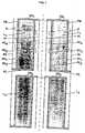
- In Fig. 1 a set of two annular beds L1 and L2 in series with the radial inward gas flow in bel L1 is schematically represented, contained on the inside of the unperforated cylindrical wall PA, in that each bed is made up of: a) a set of distributors, one in which the gas inlet is formed of two cylindrical walls coaxial one to the other, both walls PC1 and PC2 being permeable to gas. PC2 being more permeable to the gas passage than PC1; one outlet made up of two cylindridal walls coaxial one to the other, both walls PC3 and PC4 being permeable to the gas, PC4 being more permeable to the gas passage than PC3; b) a closed bottom FC placed in the delimited space on the inside of wall PC1 of the inlet collector noted in point a) and a closed external wall PA; c) an upper cover CS₁ which is placed in the delimited space in the interior of the wall PC1 of the inlet collector mentioned in point a) and the unperforated cylindrical wall PI in the gas oulet conduct coming from the outlet collector under point a).
- The collector walls (PC1, PC2, PC3 and PC4) are not generally permeable to gas for a smaller cross section TM on their upper edge (closed zone of the cylindrical walls),
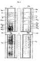
- Fig. 2 schematically represents a set of two beds in which the largest amount of gas Q travels through the beds with radial-inward flow corresponding to the largest cross section permeable to gas in the collectors, and in which the remaining smaller amount of gas Q′ goes through the beds with a substantial axial flow corresponding to the smaller cross section TM of the collectors unpermeable to gas, the above mentioned smaller cross section penetrating the catalytic bed of the upper open passage delimited by the two collectors, the upper cover CS not being persent in the zone of the catalytic bed delimited by the internal walls of the two collectors, but being limited to the zone comprised between the internal wall PC4 of the gas outlet collector and the unperforated cylindrical wall PI.
- In Fig. 3 a system of catalytic beds substantially as described in the preceeding figures is illustrated, but with radial-outward gas flow. In this case the function of the collectors is inverted (PC3 and PC4 being the inlet collector's walls and PC1 and PC2 those of the oulet collector) the closed bottom being delimited by the PC1 and PI walls and the upper cover CS being delimited by the walls PA and PC3.
- I) In an ammonia synthesis reactor with two catalytic beds with radial-outward gas flow, carried out as described in Fig. 3, the following operative conditions have been foreseen:
- 1.1 Use of a suitable catalyst with irregularly sized granules. The dimension of the granules is 1.5-3 mm;
- 1.2 Pressure drop of the gas in the catalytic bed 0.015 kg/cm2
- 1.3 Pressure drop on the PC1 wall of the inlet collector 0.02 kg/cm2 (pressure drop on the the PC2 wall of the inlet collector is negligible).
- 1.4 Pressure drop on the PC3 wall of the outlet collector 0.05 kg/cm2 (pressure drop on the PC4 wall is negligible).
- 1.5 Different pressure on the CS cover in the zone of the catalytic bed: negligible (no tightness is needed).
- II) In an ammonia synthesis reactor, as described in Fig. 2, with three catalytic beds with partially radial-inward (larger cross section) gas flow and partially axial (smaller cross section) gas flow, the following operative conditions have been foreseen:
- 2.1 Use of a suitable catalyst with irregular sized granules. The dimension of the granules is 1.5-3 mm;
- 2.2 Pressure drop of the gas in the catalytic bed 0.015 kg/cm2;
- 2.3 Pressure drop of the PC1 wall of the inlet collector 0.02 kg/cm2 (pressure drop of the PC2 wall of the inlet collector is negligible);
- 2.4 Pressure drop on the PC3 wall of the outlet collector 0.1 kg/cm2 (pressure drop on the wall PC4 is negligible);
- 2.5 Upper bed is open.
Claims (5)
Applications Claiming Priority (2)
| Application Number | Priority Date | Filing Date | Title |
|---|---|---|---|
| CH1025/86 | 1986-03-13 | ||
| CH1025/86ACH670400A5 (en) | 1986-03-13 | 1986-03-13 |
Publications (3)
| Publication Number | Publication Date |
|---|---|
| EP0237888A2 EP0237888A2 (en) | 1987-09-23 |
| EP0237888A3 EP0237888A3 (en) | 1988-05-04 |
| EP0237888B1true EP0237888B1 (en) | 1991-06-26 |
Family
ID=4200694
Family Applications (1)
| Application Number | Title | Priority Date | Filing Date |
|---|---|---|---|
| EP87103224AExpired - LifetimeEP0237888B1 (en) | 1986-03-13 | 1987-03-06 | Process to obtain an optimal gas distribution in catalytic beds for heterogeneous reactions in gaseous phase |
Country Status (9)
| Country | Link |
|---|---|
| US (1) | US4849206A (en) |
| EP (1) | EP0237888B1 (en) |
| CN (1) | CN1017970B (en) |
| CA (1) | CA1283525C (en) |
| CH (1) | CH670400A5 (en) |
| DE (1) | DE3770959D1 (en) |
| ES (1) | ES2022177B3 (en) |
| IN (1) | IN169405B (en) |
| SU (1) | SU1741600A3 (en) |
Families Citing this family (7)
| Publication number | Priority date | Publication date | Assignee | Title |
|---|---|---|---|---|
| CH670578A5 (en)* | 1987-03-25 | 1989-06-30 | Ammonia Casale Sa | |
| ES2030940T5 (en)* | 1988-06-27 | 1996-03-16 | Ammonia Casale Sa | PROCESS AND REACTOR FOR EXOTHERMAL HETEROGENOUS SYNTHESIS WITH SEVERAL CATALYTIC BEDS AND WITH EXTERNAL HEAT RECOVERY. |
| EP1818094A1 (en)* | 2006-02-13 | 2007-08-15 | Ammonia Casale S.A. | Wall system for catalytic beds of synthesis reactors |
| EP2014356A1 (en)* | 2007-07-04 | 2009-01-14 | Ammonia Casale S.A. | Wall system for catalytic beds of synthesis reactors and relative manufacturing process |
| CN105080434B (en)* | 2014-04-18 | 2018-02-27 | 新特能源股份有限公司 | A kind of catalytic reactor, system, the method for silicon tetrachloride catalytic hydrogenation |
| RU2746371C2 (en)* | 2016-09-23 | 2021-04-12 | Касале Са | Catalytic chemical reactor of axial radial flow with two catalyst layers |
| CN113856566A (en)* | 2021-10-31 | 2021-12-31 | 中国船舶重工集团公司第七一八研究所 | Multilayer combination catalytic bed convenient to dismantle |
Family Cites Families (9)
| Publication number | Priority date | Publication date | Assignee | Title |
|---|---|---|---|---|
| AT273054B (en)* | 1964-09-11 | 1969-07-25 | Haldor Frederik Axel Topsoe | Reactor for carrying out reactions in the gas phase |
| DK119652B (en)* | 1964-09-11 | 1971-02-08 | Topsoe H | Reactor for performing gas phase reactions by passing a gas mixture through a bed filled with catalyst particles. |
| AT299981B (en) | 1970-04-21 | 1972-07-10 | Chemie Linz Ag | Device for achieving uniform gas distribution in catalytic converter layers with radial flow in reactors for catalytic, exothermic high-pressure syntheses, preferably ammonia synthesis |
| US3944394A (en)* | 1974-10-31 | 1976-03-16 | Phillips Petroleum Company | Apparatus suitable for carrying out catalytic process |
| FR2365370A1 (en)* | 1976-09-22 | 1978-04-21 | Charbonnages Ste Chimique | REACTOR SUITABLE FOR CHEMICAL REACTIONS INVOLVING FLUIDS IN CONTACT WITH A BED OF SOLID MATERIALS |
| US4341737A (en)* | 1979-05-22 | 1982-07-27 | The Lummus Company | Apparatus for carrying out catalytic exothermic and endothermic high-pressure gas reactions |
| FR2460707B1 (en) | 1979-07-13 | 1986-09-05 | Ammonia Casale Sa | SYNTHESIS REACTOR, IN PARTICULAR FOR THE CATALYTIC SYNTHESIS OF AMMONIA AND METHANOL |
| IT1141102B (en) | 1980-11-28 | 1986-10-01 | Ammonia Casale Sa | AXIAL-RADIAL REACTOR FOR HETEROGENEOUS SYNTHESIS |
| DE3171985D1 (en)* | 1981-04-15 | 1985-10-03 | Uop Inc | Improved screen for collection and distribution of process streams and assembly of such screens |
- 1986
- 1986-03-13CHCH1025/86Apatent/CH670400A5/itnot_activeIP Right Cessation
- 1987
- 1987-03-06ESES87103224Tpatent/ES2022177B3/ennot_activeExpired - Lifetime
- 1987-03-06EPEP87103224Apatent/EP0237888B1/ennot_activeExpired - Lifetime
- 1987-03-06DEDE8787103224Tpatent/DE3770959D1/ennot_activeExpired - Lifetime
- 1987-03-12SUSU874202223Apatent/SU1741600A3/enactive
- 1987-03-12ININ176/MAS/87Apatent/IN169405B/enunknown
- 1987-03-13USUS07/025,600patent/US4849206A/ennot_activeExpired - Lifetime
- 1987-03-13CNCN87102931Apatent/CN1017970B/ennot_activeExpired
- 1987-03-24CACA000532796Apatent/CA1283525C/ennot_activeExpired - Lifetime
Also Published As
| Publication number | Publication date |
|---|---|
| CH670400A5 (en) | 1989-06-15 |
| SU1741600A3 (en) | 1992-06-15 |
| DE3770959D1 (en) | 1991-08-01 |
| EP0237888A3 (en) | 1988-05-04 |
| EP0237888A2 (en) | 1987-09-23 |
| CA1283525C (en) | 1991-04-30 |
| ES2022177B3 (en) | 1991-12-01 |
| CN1017970B (en) | 1992-08-26 |
| US4849206A (en) | 1989-07-18 |
| CN87102931A (en) | 1987-10-21 |
| IN169405B (en) | 1991-10-12 |
Similar Documents
| Publication | Publication Date | Title |
|---|---|---|
| JP2635283B2 (en) | Catalyst reactor bed | |
| US4769220A (en) | Converter for heterogeneous synthesis more particularly for ammonia, methanol and higher alcohols | |
| MY111823A (en) | Reactor for two-phase reactions, in particular for synthesis of urea at high pressure and temperature | |
| US3929421A (en) | Tubular catalytic reactor with premixing means for multiple reactants of different densities | |
| EP0237888B1 (en) | Process to obtain an optimal gas distribution in catalytic beds for heterogeneous reactions in gaseous phase | |
| US4735780A (en) | Ammonia synthesis converter | |
| CA1209789A (en) | Ammonia synthesis converter | |
| US5135722A (en) | Converters for heterogeneous catalytic synthesis, particularly for ammonia and methanol, under pressure | |
| US4636365A (en) | Reactor for catalytically induced or promoted reactions | |
| US4880603A (en) | Device for achieving a uniform distribution of the gas flowing radially through a catalyst bed | |
| EP0359952A3 (en) | System for the improvement of reactors for the synthesis of methanol and reactors obtained therefrom | |
| CA1317094C (en) | System to improve the efficiency of reactors for exothermic synthesis and more particularly for the reaction of ammonia | |
| EP0376000B1 (en) | Reactor for exothermic heterogeneous catalytic synthesis | |
| GB1118750A (en) | Reactor for carrying out reactions in a gaseous phase by heterogenous catalysis | |
| EP0265654A1 (en) | System and device to make catalytic basket walls for heterogeneous synthesis reactors | |
| US6165315A (en) | Reactor for the synthesis of urea | |
| EP0386692A2 (en) | System for modifying in situ reactors for the synthesis of ammonia | |
| US5184386A (en) | Method for retrofitting carbon monoxide conversion reactors | |
| EP0269854B1 (en) | Process for reducing energy consumption in multi-unit reactors for heterogeneoussynthesis and related reactors | |
| US5006316A (en) | Reactors for heterogeneous synthesis | |
| EP0285887A2 (en) | System to obtain an optimal gas distribution in catalytic beds for heterogeneous reactions in gasseous phases | |
| GB2060426A (en) | Reactor having dual upflow catalyst beds | |
| US4946657A (en) | System to reduce energy consumption in heterogeneous synthesis reactors and related reactors | |
| CA2005079C (en) | System for increasing co conversion in pre-existing reactors, and reactors obtained accordingly | |
| JPH0521023B2 (en) |
Legal Events
| Date | Code | Title | Description |
|---|---|---|---|
| PUAI | Public reference made under article 153(3) epc to a published international application that has entered the european phase | Free format text:ORIGINAL CODE: 0009012 | |
| AK | Designated contracting states | Kind code of ref document:A2 Designated state(s):DE ES FR GB GR IT NL | |
| PUAL | Search report despatched | Free format text:ORIGINAL CODE: 0009013 | |
| AK | Designated contracting states | Kind code of ref document:A3 Designated state(s):DE ES FR GB GR IT NL | |
| 17P | Request for examination filed | Effective date:19880526 | |
| 17Q | First examination report despatched | Effective date:19890727 | |
| GRAA | (expected) grant | Free format text:ORIGINAL CODE: 0009210 | |
| AK | Designated contracting states | Kind code of ref document:B1 Designated state(s):DE ES FR GB GR IT NL | |
| PG25 | Lapsed in a contracting state [announced via postgrant information from national office to epo] | Ref country code:GR Free format text:LAPSE BECAUSE OF FAILURE TO SUBMIT A TRANSLATION OF THE DESCRIPTION OR TO PAY THE FEE WITHIN THE PRESCRIBED TIME-LIMIT Effective date:19910626 | |
| ITF | It: translation for a ep patent filed | ||
| REF | Corresponds to: | Ref document number:3770959 Country of ref document:DE Date of ref document:19910801 | |
| ET | Fr: translation filed | ||
| PLBE | No opposition filed within time limit | Free format text:ORIGINAL CODE: 0009261 | |
| STAA | Information on the status of an ep patent application or granted ep patent | Free format text:STATUS: NO OPPOSITION FILED WITHIN TIME LIMIT | |
| 26N | No opposition filed | ||
| REG | Reference to a national code | Ref country code:GB Ref legal event code:IF02 | |
| PGFP | Annual fee paid to national office [announced via postgrant information from national office to epo] | Ref country code:GB Payment date:20060223 Year of fee payment:20 | |
| PGFP | Annual fee paid to national office [announced via postgrant information from national office to epo] | Ref country code:NL Payment date:20060227 Year of fee payment:20 Ref country code:DE Payment date:20060227 Year of fee payment:20 | |
| PGFP | Annual fee paid to national office [announced via postgrant information from national office to epo] | Ref country code:ES Payment date:20060309 Year of fee payment:20 | |
| PGFP | Annual fee paid to national office [announced via postgrant information from national office to epo] | Ref country code:FR Payment date:20060329 Year of fee payment:20 | |
| PGFP | Annual fee paid to national office [announced via postgrant information from national office to epo] | Ref country code:IT Payment date:20060331 Year of fee payment:20 | |
| PG25 | Lapsed in a contracting state [announced via postgrant information from national office to epo] | Ref country code:GB Free format text:LAPSE BECAUSE OF EXPIRATION OF PROTECTION Effective date:20070305 | |
| PG25 | Lapsed in a contracting state [announced via postgrant information from national office to epo] | Ref country code:NL Free format text:LAPSE BECAUSE OF EXPIRATION OF PROTECTION Effective date:20070306 | |
| PG25 | Lapsed in a contracting state [announced via postgrant information from national office to epo] | Ref country code:ES Free format text:LAPSE BECAUSE OF EXPIRATION OF PROTECTION Effective date:20070307 | |
| REG | Reference to a national code | Ref country code:GB Ref legal event code:PE20 | |
| NLV7 | Nl: ceased due to reaching the maximum lifetime of a patent | Effective date:20070306 | |
| REG | Reference to a national code | Ref country code:ES Ref legal event code:FD2A Effective date:20070307 |