EP0236518B1 - Apparatus and process for the automatic operation of operating devices of motor vehicles - Google Patents
Apparatus and process for the automatic operation of operating devices of motor vehiclesDownload PDFInfo
- Publication number
- EP0236518B1 EP0236518B1EP86103148AEP86103148AEP0236518B1EP 0236518 B1EP0236518 B1EP 0236518B1EP 86103148 AEP86103148 AEP 86103148AEP 86103148 AEP86103148 AEP 86103148AEP 0236518 B1EP0236518 B1EP 0236518B1
- Authority
- EP
- European Patent Office
- Prior art keywords
- actuating
- fact
- housing
- lever
- situated
- Prior art date
- Legal status (The legal status is an assumption and is not a legal conclusion. Google has not performed a legal analysis and makes no representation as to the accuracy of the status listed.)
- Expired
Links
- 238000000034methodMethods0.000titleclaimsabstractdescription13
- 230000008569processEffects0.000titleclaimsabstractdescription8
- 239000000725suspensionSubstances0.000claimsdescription5
- 230000011664signalingEffects0.000claimsdescription2
- 238000009434installationMethods0.000description4
- 230000001133accelerationEffects0.000description2
- 230000006978adaptationEffects0.000description2
- 230000008878couplingEffects0.000description2
- 238000010168coupling processMethods0.000description2
- 238000005859coupling reactionMethods0.000description2
- 238000005259measurementMethods0.000description2
- 230000009471actionEffects0.000description1
- 238000004873anchoringMethods0.000description1
- 238000010276constructionMethods0.000description1
- 230000000994depressogenic effectEffects0.000description1
- 239000000446fuelSubstances0.000description1
- 230000007246mechanismEffects0.000description1
- 230000036316preloadEffects0.000description1
- 230000000284resting effectEffects0.000description1
- 230000000717retained effectEffects0.000description1
- 238000005096rolling processMethods0.000description1
- 239000013585weight reducing agentSubstances0.000description1
Images


Classifications
- G—PHYSICS
- G01—MEASURING; TESTING
- G01M—TESTING STATIC OR DYNAMIC BALANCE OF MACHINES OR STRUCTURES; TESTING OF STRUCTURES OR APPARATUS, NOT OTHERWISE PROVIDED FOR
- G01M17/00—Testing of vehicles
- G01M17/007—Wheeled or endless-tracked vehicles
- G01M17/0072—Wheeled or endless-tracked vehicles the wheels of the vehicle co-operating with rotatable rolls
- G01M17/0074—Details, e.g. roller construction, vehicle restraining devices
- B—PERFORMING OPERATIONS; TRANSPORTING
- B60—VEHICLES IN GENERAL
- B60T—VEHICLE BRAKE CONTROL SYSTEMS OR PARTS THEREOF; BRAKE CONTROL SYSTEMS OR PARTS THEREOF, IN GENERAL; ARRANGEMENT OF BRAKING ELEMENTS ON VEHICLES IN GENERAL; PORTABLE DEVICES FOR PREVENTING UNWANTED MOVEMENT OF VEHICLES; VEHICLE MODIFICATIONS TO FACILITATE COOLING OF BRAKES
- B60T17/00—Component parts, details, or accessories of power brake systems not covered by groups B60T8/00, B60T13/00 or B60T15/00, or presenting other characteristic features
- B60T17/18—Safety devices; Monitoring
- B60T17/22—Devices for monitoring or checking brake systems; Signal devices
- B60T17/221—Procedure or apparatus for checking or keeping in a correct functioning condition of brake systems
- B60T17/222—Procedure or apparatus for checking or keeping in a correct functioning condition of brake systems by filling or bleeding of hydraulic systems
- B60T17/223—Devices for pressurising brake systems acting on pedal
Definitions
- the inventionrelates to a method for the automatic movement of a motor vehicle actuating part by a driving device, a connection being made mechanically between the driving device housing and the actuating part, and a device for carrying out the method with a housing arranged in the passenger compartment of a motor vehicle and driven, extendable connecting parts arranged thereon.
- the clutchis used, as a result of the different trajectories from the clutch pedal and rod end, forces are exerted on the rod. Since the roller itself only reduces the frictional forces, however, the force components act in the normal direction to the rolling path of the roller on the curved tread of the clutch pedal.
- the object of the inventionis to set up and actuate motor vehicle actuation parts arranged in a predetermined position against each other by means of arresting arranged driving devices so that practically no constraining forces are transmitted to the motor vehicle actuation parts and that the already installed driver's seat remains installed.
- This objectis achieved by the characterizing features of method claim 1.
- a mechanical connecting partis assigned to each actuating part, the constraining forces occurring in each connecting part being compensated for independently and separately from one another.
- the device for carrying out the methodwhich is protected in claim 3 and which starts from a housing which is locked in the passenger compartment of a motor vehicle and is arranged on this, driven, extendable connecting parts, according to the invention provides an actuating housing with a connecting part for the gas, brake and Clutch pedal in front, wherein each connecting part can be oriented to the corresponding actuating part and further that a switch housing is also provided in the footwell of the motor vehicle, which contains two drives for a connecting part to the shift lever, and that both housings can be connected within the vehicle, and that at least one of the is reproducibly locked in both housings on a reference platform, the reference platform being supported on the steering wheel of the vehicle and being able to be aligned thereon.
- the vehicle seatdoes not have to be removed or loaded and that by dividing the driving device into two housings for gas, clutch, brake and a switching device the individual weight to be brought into the vehicle interior is reduced. This eliminates lifting devices.
- the arrangement of the two housings in the footwell in front of the vehicle seat, as protected in claim 4,achieves a compact construction of the driving device in which an alignment of the connecting parts to the actuating parts can be achieved by arranging operating means according to the invention on the individual housings.
- Claim 5provides yet another configuration of the driving device, which is broken down into two components, which can also be locked on the reference platform.
- the connecting partcan be aligned with the corresponding actuating part via its base plate, which carries a suspension axis and is connected to the actuating housing.
- the drive and the storage of the connecting partare put under protection, the connecting part being protected during the installation phase, essentially housed within the actuating housing and being swung out of the housing only during operation and, if the connecting part does not match the actuating part, constraining forces are thereby avoided that as a result of support via a support spring, a hinge point of the resulting four-bar linkage can shift.
- the drive arranged according to the invention on the base plate for the connecting part pivoting out on a trajectoryremotely controllable servo, electrical, pneumatic or hydraulic drives can be used.
- This connecting part defined in this wayis arranged in the actuating housing during transport or setting up. After inserting the actuating housing into the footwell of a motor vehicle and locking the housing on the steering wheel, the connecting part, which is connected via joints, is moved out of the housing on a trajectory until it comes into frictional engagement with the actuating end piece after alignment of the base plate, for example with the accelerator pedal .
- a switchis arranged on the articulated lever, which signals the contact between the actuating part and the actuating end piece.
- a force measuring elementis placed under protection, with which the actuating forces on the actuating part can be measured.
- Claim 11provides a special configuration of the actuating end piece under protection, in which the relative direction of force is practically retained even when the contact point changes.
- a particularly advantageous embodiment of the connecting partis protected in claim 13.
- a clear, unrestricted movement of the switching device of the motor vehicleis brought about by means of a rotatably connected lever and a movable grip shell, which comprises the shift knob.
- the remote control devices placed under protection in claim 16show inventive possibilities for causing an actuation of the connecting parts from the outside.
- Claim 19shows an inventive connection between the reference platform and the steering wheel, in which on the one hand steering wheel movements in the area of interest are not hindered and on the other hand a firm anchoring of the housing is achieved.
- actuating device housing 4 and a switch housing 5connected to a cross strut 6 of the anchorage of the driver's seat 1 with a fork-like holder 7.
- the actuating housing 4 and the switching housing 5are connected via a console 8, on which the fork-like holder 7 is also arranged.
- the two housings 4, 5are connected to lockable retaining tabs 9, so that, as shown in FIG. 1, it is sufficient if a connecting rod 10 acts on the switch housing 5 and, on the other hand, in a clamping device 11 on a connecting plate 12 and locks is slidably mounted.
- the connecting plate 12is supported on a base plate 13, which carries ball guides for the connecting bar 12 and which in turn is connected to the steering wheel 14 in an alignable manner.
- a steering movement on the steering wheel 14is possible during the examinations.
- the switch housing 5can also be connected via a connection 15 to the actuating housing 4, which then takes the place of the switch housing 5, as shown in dashed lines and provided with the reference symbol 5 '.
- the connecting rod 10can be arranged on the actuating housing 4, or also on the switch housing 5 '. It is also possible to bring the actuating housing 4 into the position of the switch housing 5 '.
- connecting parts 20are provided between the actuating housing 4 and an actuating part 21 in the exemplary embodiment of the brake pedal.
- the accelerator or clutch pedalcan also be depressed or all three pedals can be connected to the actuating housing 4 with three separate connecting parts 20.
- the further connecting parts 50 shown in detail in FIG. 3act as the connecting part between the switching housing 5 and a shift lever 60 shown in FIG. 3.
- FIG. 1the connecting parts 20, which are explained in connection with FIG. 2, are shown in the extended state, i. H. the connecting parts 20 have frictionally engaged with the actuating parts 21 and are supported against the actuating housing 4.
- the connecting parts 20, which are explained in more detail in FIG. 2,are pivoted into the footwell of the motor vehicle when the actuating housing is being installed and removed, so that the contour of the actuating housing 4 appears as a narrow rectangle which can easily be introduced into the footwell through the driver's door.
- the two housings 4 and 5are separated from one another during installation, so that the installation and removal of the housing can take place without damage; by dividing the driving device into two housings, a weight reduction for the individually manipulated housing is also achieved, so that no additional auxiliary devices, as previously absolutely necessary, are required.
- the actuating housing 4 shown in section in FIG. 2has a base plate 22 for each actuating part 21, 21 ', 21 "", which is connected to the actuating housing 4 via a suspension axis 23.
- the base plate 22is aligned about its suspension axis 23 by means of remotely controllable adjusting means 24 to the actuating part 21 or 21 ', 21 "so that when pivoting the connecting part 20 or 20', 20" this with the actuating part in Friction can occur.
- Each connecting partis driven by a rotary drive, which can be servo-electric, servo-pneumatic or servo-hydraulic, via a shaft 25.
- a rotary lever 26is attached to the shaft 25. When the shaft 25 is moved counterclockwise, the rotary lever 26 is pivoted out of its position I out of the actuating housing 4 to the position II for contact with the actuating lever 21.
- the actuation forceis introduced as a torque and radial support force through the shaft 25.
- a driver 27which, when the rotary lever 26 is moved in the clockwise direction, that is to say when the connecting part 20 is pivoted into the actuating housing, pivots a rocker arm 28 about an axis of rotation 29 arranged orthogonally to the base plate 22, so that it can be pulled out Support rod 30, which is also arranged on the rocker 28, an articulated lever 31, which is connected to the rotary lever 26 via a rotary connection 32, can be returned from position 11 to position I.
- the articulated lever 31carries, at its free end, an actuating end piece 33 in a rotatable manner. In the contact area between the actuating end piece 33 and the actuating part 21, the path curve is selected such that it approximately follows the pedal movement of the accelerator pedal or the brake pedal or the clutch pedal.
- the articulated lever 31also carries a signaling switch 34, which is actuated when the actuating end piece 33 is in contact with the actuating part 21 due to the low pivotability, for example 1 ° about an articulation 35, and thus reports back the frictional engagement.
- the actuating end piece 33also carries a force measuring element 36.
- the force measuring elementis equipped with connections for remote display of the actuating forces. Strain gauges can also replace the force measuring element.
- the side of the force measuring element 36which comes into operative connection with the actuating part 21, 21 ', 21 "or, when using strain gauges, the opposite side of the actuating part 21 of the actuating end piece 33 is formed such that the forces occurring practically in the direction of the axis of rotation of the rotary connection 32 act.
- a stop 38is provided in the actuating housing 4.
- This stop 38is for each connecting part 20, 20', 20" provided separately and can be set like the adjusting means 24, for example via cable pulls which are set manually by spindle drives or servo-setting drives.
- the rocker 28is stopped by an auxiliary rod 39 38 held.
- the rocker arm 28is held in a defined position at a pivot point 41 of the rocker arm 28 by means of a support spring 40. As long as the support force of the extendable support rod 30 acting on the pivot point 41 is smaller than the spring force of the support spring 40.
- the connecting line between the contact point 37 and the axis of rotation of the rotary connection 32is approximately perpendicular to the line contact point 37 and pivot point 42 of the actuating part 21, 21 ', 21 ".
- the further connecting part 50 shown in FIG. 3is caused by a rotary drive 51 arranged in the switch housing 5 and a longitudinal drive 52 to move back and forth and to make a rotary movement.
- the further connecting memberis guided through the longitudinal drive 52 in the shift gate of the gear shift of the vehicle, while the rotary drive pivots the further connecting part 50 in the switching direction.
- the rotary drive 51carries a bearing pin 54 (see FIG. 3a) on which a lever 55 is arranged to be movable in the longitudinal direction.
- the lever 55is pivoted by means of a sliding sleeve 56 and coupling member 57, which is articulated on the shaft 58 of the lever 55.
- the lever 55is connected at its free end via a joint 59 to a further lever 61 which carries a handle shell 63 which is movable about a shell joint 62 and which comprises the knob 64 of a shift lever 60 in a spring-loaded manner.
- Lever 55 and other levers 61are also connected via a spring 65, which ensures that a certain contact pressure of the further lever 61 is generated on the shift knob 64.
- a support rod 66which is arranged between the further lever 61 and the free end 53 of the shaft, is extended by the action of force without the pretensioning of the grip shell 63 is solved. This shifts the gear lever into the gear level required for engaging reverse gear.
- An articulated rod 67 arranged on the lever 55is connected to an extension 68 that extends beyond the shell joint. This ensures that the grip 63 is guided for the switching process.
- Drive devices 69, 70which in the exemplary embodiment are arranged in the switch housing, but which can also be arranged outside the switch housing and outside the vehicle, are provided via Bowden cables 71 and 72 with the support rod 66 for introducing forces or for locking this support rod or the Bowden cable 72 is arranged between the drive device 70 and the handle shell 63, so that the pretensioning of the handle shell 63 applied by a clamping spring 73 can be released (cf. FIG. 36).
- the length of the lever 55 between the bearing pin 54 and the joint 59is equal to the length between the shift knob center 74 and the center of rotation 75 of the shift lever 60; and the distance between the center of rotation 75 and the journal 54 is equal to the distance between the joint 59 and the center of the gear knob 74.
- the points 54, 59, 74 and 75thus form a parallelogram.
- the drive mechanism 70 and the Bowden cable 72open the grip shell 63, and at the same time the support rod 66 is locked by the drive device 69 via the Bowden cable 71, so that the switching knob can move freely.
- the further connecting partcan be adapted to the gear shift of each vehicle.
Landscapes
- Engineering & Computer Science (AREA)
- Transportation (AREA)
- Mechanical Engineering (AREA)
- Physics & Mathematics (AREA)
- General Physics & Mathematics (AREA)
- Mechanical Control Devices (AREA)
- Arrangement And Mounting Of Devices That Control Transmission Of Motive Force (AREA)
- Gear-Shifting Mechanisms (AREA)
- Control Of Electric Motors In General (AREA)
- Control Of Multiple Motors (AREA)
- Arrangement Or Mounting Of Control Devices For Change-Speed Gearing (AREA)
Abstract
Description
Translated fromGermanDie Erfindung betrifft ein Verfahren zur automatischen Bewegung eines Kraftfahrzeugbetätigungsteils durch eine Fahreinrichtung, wobei zwischen Fahreinrichtungsgehäuse und Betätigungsteil mechanisch eine Verbindung hergestellt wird sowie eine Vorrichtung zur Durchführung des Verfahrens mit einem im Fahrgastraum eines Kraftfahrzeugs arretiert angeordneten Gehäuse und an diesem angeordneten, angetriebenen, ausfahrbaren Verbindungsteilen.The invention relates to a method for the automatic movement of a motor vehicle actuating part by a driving device, a connection being made mechanically between the driving device housing and the actuating part, and a device for carrying out the method with a housing arranged in the passenger compartment of a motor vehicle and driven, extendable connecting parts arranged thereon.
Wenn Kraftfahrzeuge komplett hergestellt sind, ist eine Funktionskontrolle erforderlich. Zur Funktionskontrolle der Betätigungsteile, die vom Fahrersitz aus bewegt werden, wird das Fahrzeug auf einen Rollenprüfstand gefahren und dort die Betätigungsteile wie Gaspedal, Kupplungspedal und Bremspedal einerseits sowie die Schalteinrichtung andererseits auf ihre Funktionsfähigkeit untersucht. Um dies zu ermöglichen, hat man bisher z. B. den Fahrzeugsitz ausgebaut und anstelle des Sitzes eine Fahreinrichtung eingebaut, die über Verbindungselemente zwischen der Faheinrichtung und dem Gas-, Brems- und Kupplungspedal einerseits und einem Verbindungsmittel zwischen Fahreinrichtung und Schalthebel andererseits sowohl Beschleunigungs- und Verzögerungsvorgänge als auch Schaltvorgänge bewirkt. Der Betrieb einer derartigen Einrichtung ist wegen des erforderlichen Ausbaus des Fahrersitzes zeitaufwendig. Auch erfordert die Anpassung der Verbindungselemente zu den Pedalen im Hinblick auf die Ausrichtung und im Hinblick darauf, daß im Ruhezustand noch keine Betätigung der Einzelpedale auftreten soll, einen beachtlichen Arbeitsaufwand. Um die Untersuchungsergebnisse verschiedener Fahrzeuge miteinander zu vergleichen, ist bei jedem Fahrzeug der Serie darauf zu achten, daß trotz der zugelassenen Toleranz der Anordnung der Betätigungseinrichtung beispielsweise ein Schleifen der Kupplung oder der Bremse oder ein nicht völliges Ausrücken des Ganges vermieden wird, wenn die Verbindungselemente zwischen Fahreinrichtung und Betätigungsteil in ihrer Ausgangsstellung sind. Gleichzeitig ist zu vermeiden, daß große Leerwege zurückgelegt werden müssen, bis das Verbindungsmittel mit dem Betätigungsteil in Verbindung tritt, beispielsweise dann, wenn für Kraftstoff Verbrauchsmessungen und Abgasuntersuchungen in vorgegebenen Zeitabständen eine Folge von Schaltvorgängen, Beschleunigungs- und Verzögerungsvorgängen durchgeführt werden soll. Das geringe Raumangebot im Bereich der Betätigungsteile tritt noch erschwerend für die erforderlichen Einstellarbeiten hinzu.If motor vehicles are completely manufactured, a functional check is required. In order to check the function of the operating parts that are moved from the driver's seat, the vehicle is driven to a roller test bench and the operating parts such as the accelerator pedal, clutch pedal and brake pedal on the one hand and the switching device on the other hand are examined for their functionality. To make this possible, z. B. removed the vehicle seat and installed a driving device instead of the seat, which causes both acceleration and deceleration processes and switching processes via connecting elements between the wheel device and the accelerator, brake and clutch pedal on the one hand and a connecting means between the driving device and shift lever on the other hand. The operation of such a device is time-consuming because of the need to remove the driver's seat. Also, the adaptation of the connecting elements to the pedals with respect to the alignment and in view of the fact that no actuation of the individual pedals is to occur in the idle state requires a considerable amount of work. In order to compare the test results of different vehicles with each other, care must be taken with every vehicle in the series that despite the permitted tolerance of the arrangement of the actuating device, for example, a clutch or brake grinding or an incomplete disengagement of the gear is avoided if the connecting elements between Driving device and operating part are in their starting position. At the same time, it is to be avoided that large idle distances have to be covered until the connecting means comes into contact with the actuating part, for example when a sequence of switching operations, acceleration and deceleration operations is to be carried out at predetermined intervals for fuel consumption measurements and exhaust gas analyzes. The small amount of space in the area of the actuating parts makes it even more difficult for the necessary adjustment work.
Es wird auch versucht, anstelle des Ausbaus des Kraftfahrzeugsitzes eine Fahreinrichtung auf dem eingebauten Fahrzeugsitz anzuordnen und diese dabei an der Lehne des Fahrzeugsitzes abzustützen und an den Seiten des Sitzpolsters zu orientieren. Hierdurch wird die Zeit des Ein- und Ausbaus des Fahrzeugsitzes eingespart, hierzu ist jedoch eine zusätzliche Halteeinrichtung außerhalb des Fahrzeugs erforderlich (DE-Al 3 303 588). In Bezug auf die exakte Einstellung werden jedoch die aufgezeigten Nachteile mit übernommen bzw. noch vergrößert, da die Rücklehne und Seitenteile des Kraftfahrzeugsitzes in der Regel verstellbar und elastisch sind sowie Einbautoleranzen unterliegen. Auch wenn als Verbindungselement ein einstellbarer Stab mit einer Rolle zur Auflage auf dem zu betätigenden Betätigungsteil z.B. der Kupplung verwendet wird, entstehen infolge der verschiedenen Bewegungsbahnen vom Kupplungspedal und Stabende Zwangskräfte auf den Stab. Da die Rolle selbst lediglich die Reibungskräfte herabsetzt, jedoch die Kraftkomponenten in Normalenrichtung zur Abrollbahn der Rolle auf der gekrümmten Trittfläche des Kupplungspedals wirken.Attempts are also being made to arrange a driving device on the built-in vehicle seat instead of removing the motor vehicle seat and to support it on the back of the vehicle seat and to orient it on the sides of the seat cushion. This saves the time for installing and removing the vehicle seat, but this requires an additional holding device outside the vehicle (DE-Al 3 303 588). With regard to the exact setting, however, the disadvantages shown are taken over or increased, since the backrest and side parts of the motor vehicle seat are generally adjustable and elastic and are subject to installation tolerances. Even if an adjustable rod with a roller for resting on the actuating part to be actuated, e.g. the clutch is used, as a result of the different trajectories from the clutch pedal and rod end, forces are exerted on the rod. Since the roller itself only reduces the frictional forces, however, the force components act in the normal direction to the rolling path of the roller on the curved tread of the clutch pedal.
Ausgehend hiervon liegt der Erfindung die Aufgabe zugrunde, in vorgegebener Lage angeordnete Kraftfahrzeugbetätigungsteile durch arretiert angeordnete Fahreinrichtungen gegeneinander so einzurichten und zu betätigen, daß hierbei praktisch keine Zwangskräfte auf die Kraftfahrzeugbetätigungsteile übertragen werden und daß der bereits montierte Fahrersitz eingebaut bleibt. Diese Aufgabe wird durch die kennzeichnenden Merkmale des Verfahrensanspruchs 1 gelöst. Durch eine Orientierung des Verbindungsteils am Betätigungsteil und durch die Kompensation auftretender Zwangskräfte, hervorgerufen durch vorgegebene unterschiedliche Bahnkurven von Betätigungsteil und Verbindungsteil während der Betätigung, werden aussagekräftige Meßergebnisse erreicht, die reproduzierbar sind. Dies gilt auch für extreme seitliche Abweichungen zwischen Fahreinrichtung und Betätigungsteil.Proceeding from this, the object of the invention is to set up and actuate motor vehicle actuation parts arranged in a predetermined position against each other by means of arresting arranged driving devices so that practically no constraining forces are transmitted to the motor vehicle actuation parts and that the already installed driver's seat remains installed. This object is achieved by the characterizing features of method claim 1. By orienting the connecting part on the actuating part and by compensating the constraining forces caused by predetermined different trajectories of the actuating part and the connecting part during actuation, meaningful measurement results are achieved which are reproducible. This also applies to extreme lateral deviations between the driving device and the actuating part.
In Ausgestaltung des erfinderischen Verfahrens wird jedem Betätigungsteil ein mechanisches Verbindungsteil zugeordnet, wobei die in jedem Verbindungsteil auftretenden Zwangskräfte unabhängig und getrennt voneinander kompensiert werden.In an embodiment of the method according to the invention, a mechanical connecting part is assigned to each actuating part, the constraining forces occurring in each connecting part being compensated for independently and separately from one another.
Die in Anspruch 3 unter Schutz gestellte Vorrichtung zur Durchführung des Verfahrens, die von einem im Fahrgastraum eines Kraftfahrzeugs arretiert angeordneten Gehäuse und an diesem angeordneten, angetriebenen, ausfahrbaren Verbindungsteilen ausgeht, sieht erfindungsgemäß ein Betätigungsgehäuse mit je einem Verbindungsteil für das Gas-, Brems- und Kupplungspedal vor, wobei jedes Verbindungsteil zum entsprechenden Betätigungsteil orientierbar ist und weiterhin daß ein ebenfalls im Fußraum des Kraftfahrzeugs angeordnetes Schaltgehäuse vorgesehen ist, das zwei Antriebe für ein Verbindungsteil zum Schalthebel enthält, und daß beide Gehäuse innerhalb des Fahrzeuges verbindbar sind, und daß mindestens eines der beiden Gehäuse an einer Bezugsplattform reproduzierbar arretiert wird, wobei sich die Bezugsplattform am Lenkrad des Fahrzeugs abstützt und an diesem ausrichtbar ist. Mit dieser erfindungsgemäßen Vorrichtung wird zum einen erreicht, daß der Fahrzeugsitz nicht entfernt oder belastet werden muß und daß durch Aufteilung der Fahreinrichtung in zwei Gehäuse für Gas, Kupplung, Bremse und einer Schalteinrichtung das in das Fahrzeuginnere zu verbringende Einzelgewicht reduziert wird. Hierdurch entfallen Hubeinrichtungen.The device for carrying out the method, which is protected in claim 3 and which starts from a housing which is locked in the passenger compartment of a motor vehicle and is arranged on this, driven, extendable connecting parts, according to the invention provides an actuating housing with a connecting part for the gas, brake and Clutch pedal in front, wherein each connecting part can be oriented to the corresponding actuating part and further that a switch housing is also provided in the footwell of the motor vehicle, which contains two drives for a connecting part to the shift lever, and that both housings can be connected within the vehicle, and that at least one of the is reproducibly locked in both housings on a reference platform, the reference platform being supported on the steering wheel of the vehicle and being able to be aligned thereon. With this device according to the invention it is achieved on the one hand that the vehicle seat does not have to be removed or loaded and that by dividing the driving device into two housings for gas, clutch, brake and a switching device the individual weight to be brought into the vehicle interior is reduced. This eliminates lifting devices.
Durch die Anordnung der beiden Gehäuse im Fußraum vor dem Fahrzeugsitz, wie in Anspruch 4 unter Schutz gestellt, wird eine Kompaktbauweise der Fahreinrichtung erreicht, bei der durch erfindungsgemäße Anordnung von Bedienungsmitteln an den einzelnen Gehäusen eine Ausrichtung der Verbindungsteile zu den Betätigungsteilen erreichbar ist.The arrangement of the two housings in the footwell in front of the vehicle seat, as protected in
Anspruch 5 stellt eine noch weitere Konfiguration der in zwei Bauteile aufgelösten Fahreinrichtung unter Schutz, die ebenfalls an der Bezugsplattform arretierbar ist.
Durch die in Anspruch 6 unter Schutz gestellten Stellmittel, die am Betätigungsgehäuse angeordnet sind, ist das Verbindungsteil über seine Grundplatte, die eine Aufhängeachse trägt und mit dieser mit dem Betätigungsgehäuse verbunden, zu dem entsprechenden Betätigungsteil ausrichtbar.By means of the actuating means that are placed under protection in
In Anspruch 7 wird der Antrieb und die Lagerung des Verbindungsteils unter Schutz gestellt, wobei das Verbindungsteil während der Aufstellphase geschützt im Wesentlichen innerhalb des Betätigungsgehäuses untergebracht ist und erst beim Betrieb aus dem Gehäuse ausgeschwenkt wird und bei Nichtübereinstimmung des Verbindungsteils mit dem Betätigungsteil Zwangskräfte dadurch vermieden werden, daß infolge Abstützung über eine Stützfeder sich ein Gelenkpunkt des sich ergebenden Gelenkvierecks verschieben kann. Bei dem an der Grundplatte erfindungsgemäß angeordneten Antrieb für das auf einer Bahnkurve ausschwenkende Verbindungsteil können fernbedienbare servo-, elektrisch-, pneumatisch- oder hydraulische Antriebe verwendet werden.In
Die in Anspruch 8 unter Schutz gestellte erfinderische Ausgestaltung eines Verbindungsteils sieht einen angetriebenen Drehhebel vor, der einen Mitnehmer trägt und der an seinem freien Ende über eine Drehverbindung mit einem Gelenkhebel verbunden ist, wobei der Gelenkhebel einerseits über eine ausziehbare Stützstange mit der Schwinge verbunden ist und andererseits mit einem Betätigungsendstück. Dieses so definierte Verbindungsteil ist während des Transports bzw. Einrichtens im Betätigungsgehäuse angeordnet. Nach Einbringen des Betätigungsgehäuses in den Fußraum eines Kraftfahrzeugs und Arretierung des Gehäuses am Lenkrad wird durch Antreiben das über Gelenke verbundene Verbindungsteil auf einer Bahnkurve aus dem Gehäuse herausbewegt, bis es mit dem Betätigungsendstück nach Ausrichtung der Grundplatte reibschlüssig, beispielsweise mit dem Gaspedal, in Verbindung tritt.The inventive protection of a connecting part, which is protected in
Gemäss Anspruch 9 ist in Ausgestaltung des Erfindungsgegenstandes am Gelenkhebel ein Schalter angeordnet, der die Berührung zwischen Betätigungsteil und Betätigungsendstück signalisiert.According to
In noch weiterer Ausgestaltung des Erfindungsgegenstandes wird in Anspruch 10 ein Kraftmeßelement unter Schutz gestellt, mit dem die Betätigungskräfte auf das Betätigungsteil gemessen werden können.In yet another embodiment of the subject matter of the invention, a force measuring element is placed under protection, with which the actuating forces on the actuating part can be measured.
Anspruch 11 stellt eine besondere Ausgestaltung des Betätigungsendstücks unter Schutz, bei dem die relative Kraftrichtung auch bei Änderung des Berührpunktes praktisch erhalten bleibt.
Durch den gemäß Anspruch 12 unter Schutz gestellten Drehantrieb mit Lagerzapfen im Schaltgehäuse der mit einem ebenfalls im Schaltgehäuse angeordneten Längsantrieb zusammenwirkt, wird erreicht, daß über eine Schiebemuffe und ein Koppelglied das Verbindungsteil sowohl drehbar als auch längsverschieblich angetrieben wird...Due to the rotary actuator protected under
Eine besonders vorteilhafte Ausgestaltung des Verbindungsteils wird in Anspruch 13 unter Schutz gestellt. Hierbei wird mittels drehbeweglich verbundender Hebel und einer beweglichen Griffschale, die den Schaltknauf umfaßt, eine eindeutige zwangfreie Bewegung der Schalteinrichtung des Kraftfahrzeugs bewirkt.A particularly advantageous embodiment of the connecting part is protected in
Durch die Anordnung einer Zusatzfeder wird verhindert, daß die Griffschale den Formschluß zum Schaltknauf verliert, wie in Anspruch 14 unter Schutz gestellt.The arrangement of an additional spring prevents the grip shell from losing the positive connection to the shift knob, as is protected in
Durch eine einstellbare und durch Fernbedienung arretierbare Stützstange und die Anordnung eines Gelenkstabs zwischen Hebel und beweglicher Griffschale, wie in Anspruch 15 unter Schutz gestellt, wird zum einen eine exakte Führung der Griffschale und zum anderen eine Beweglichkeit des Schaltknüppels ohne Zwangskräfte erreicht.An adjustable and lockable by remote control support rod and the arrangement of an articulated rod between the lever and movable handle, as protected in
Die in Anspruch 16 unter Schutz gestellten Fernbedienungseinrichtungen zeigen erfinderische Möglichkeiten, eine Betätigung der Verbindungsteile von außen her zu bewirken.The remote control devices placed under protection in claim 16 show inventive possibilities for causing an actuation of the connecting parts from the outside.
Die in Anspruch 17 unter Schutz gestellte Gleichheit der Längen entsprechender Bauteile bietet praktisch die Gewähr für eine Betätigung des Schalthebels ohne Zwangskräfte.The equality of the lengths of corresponding components, which is protected in claim 17, offers practically the guarantee of actuation of the shift lever without constraining forces.
Durch Verlängerung der entsprechenden Hebel, wie in Anspruch 18 unter Schutz gestellt, ist eine Anpassung der für die Schalteinrichtung zuständigen Fahreinrichtung an beliebige Fahrzeuge möglich.By extending the corresponding lever, as protected in claim 18, an adaptation of the driving device responsible for the switching device to any vehicle is possible.
Anspruch 19 zeigt eine erfinderische Verbindung zwischen Bezugsplattform und Lenkrad, bei der einerseits Lenkradbewegungen im interessierenden Bereich nicht behindert werden und bei der andererseits eine feste Verankerung der Gehäuse erreicht wird.Claim 19 shows an inventive connection between the reference platform and the steering wheel, in which on the one hand steering wheel movements in the area of interest are not hindered and on the other hand a firm anchoring of the housing is achieved.
In der nachfolgenden Zeichnung wird der Erfindungsgegenstand näher erläutert.The subject matter of the invention is explained in more detail in the following drawing.
Es zeigen:
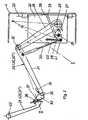
- Fig. 1 eine Anordnung des Erfindungsgegenstandes im Kraftfahrzeug
- Fig. 2 ein erfindungsgemäßes Betätigungsgehäuse im Schnitt einschließlich Verbindungsteil und Betätigungsteil
- Fig. 2a eine Draufsicht auf die Anordnung gemäß Fig. 2 im Bereich des Gehäuses
- Fig. 3 ein erfindungsgemäßes Schaltgehäuse im Schnitt einschließlich Verbindungsteil und Betätigungsteil
- Fig. 3a eine Ansicht des Schaltgehäuses und
- Fig. 3b eine vergrößerte Draufsicht auf die erfindungsgemäße Griffschale.
- Fig. 1 shows an arrangement of the subject of the invention in the motor vehicle
- Fig. 2 shows an actuating housing according to the invention in section including the connecting part and the actuating part
- FIG. 2a shows a top view of the arrangement according to FIG. 2 in the area of the housing
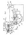
- Fig. 3 shows a switch housing according to the invention in section including connecting part and actuating part
- 3a is a view of the switch housing and
- 3b is an enlarged top view of the grip shell according to the invention.
Gemäß Fig. 1 sind vor einem Fahrersitz 1 am Boden 2 eines Kraftfahrzeugs 3 ein Betätigungsgehäuse 4 und ein Schaltgehäuse 5 an einer Querstrebe 6 der Verankerung des Fahrersitzes 1 mit einer gabelartigen Halterung 7 verbunden. Das Betätigungsgehäuse 4 und das Schaltgehäuse 5 sind über eine Konsole 8, an der auch die gabelartige Halterung 7 angeordnet ist, verbunden. Andererseits sind die beiden Gehäuse 4, 5 mit arretierbaren Haltelaschen 9 verbunden, so daß es, wie in Fig. 1 dargestellt, ausreichend ist, wenn ein Verbindungsstab 10 am Schaltgehäuse 5 angreift und zum anderen in einer Klemmeinrichtung 11 an einer Anschlußplatte 12 arretier- und verschiebbar gelagert ist. Die Anschlußplatte 12 stützt sich an einer Grundplatte 13 ab, die Kugelführungen für die Anschlußlatte 12 trägt und die ihrerseits ausrichtbar mit dem Lenkrad 14 verbunden ist. Durch die Lagerung der Anschlußplatte 12 über Kugeln gegenüber der Grundplatte 13 ist während der Untersuchungen eine Lenkbewegung am Lenkrad 14 möglich.1 are in front of a driver's seat 1 on the
Anstelle der Anordnung des Schaltgehäuses 5 auf der Konsole 8 kann dieses, wie gestrichelt dargestellt und mit dem Bezugszeichen 5' versehen, auch über eine Verbindung 15 mit dem dann an die Stelle des Schaltgehäuses 5 getretenen Betätigungsgehäuse 4 verbunden sein. Hierbei kann der Verbindungsstab 10 am Betätigungsgehäuse 4 angeordnet sein, oder auch am Schaltgehäuse 5'. Auch ist es möglich, das Betätigungsgehäuse 4 in die Lage des Schaltgehäuses 5' zu bringen.Instead of arranging the
Wie der Fig. 1 weiter entnehmbar ist, sind Verbindungsteile 20 zwischen dem Betätigungsgehäuse 4 und einem Betätigungsteil 21 im Ausführungsbeispiel dem Bremspedal vorgesehen. Anstelle des Bremspedals kann jedoch auch das Gas- oder Kupplungspedal treten oder es können alle drei Pedale mit drei getrennten Verbindungsteilen 20 mit dem Betätigungsgehäuse 4 verbunden sein.As can also be seen in FIG. 1, connecting
Als Verbindungsteil zwischen dem Schalteghäuse 5 und einem in Fig. 3 dargestellten Schalthebel 60 treten die in Fig. 3 ausführlich dargestellten weiteren Verbindungsteile 50.The further connecting
In Fig. 1 sind die Verbindungsteile 20, die im Zusammenhang mit Fig. 2 näher erläutert werden, im ausgefahrenen Zustand dargestellt, d. h. die Verbindungsteile 20 haben mit den Betätigungsteilen 21 Reibverbindung aufgenommen und stützen sich selbst gegen das Betätigungsgehäuse 4 ab. Die in Fig. 2 näher erläuterten Verbindungsteile 20 werden beim Ein- und Ausbau des Betätigungsgehäuses in den Fußraum des Kraftfahrzeugs eingeschwenkt, so daß die Kontur des Betätigungsgehäuses 4 als schmales Rechteck erscheint, welches ohne weiteres durch die Fahrertür in den Fußraum eingebracht werden kann. Darüber hinaus sind die beiden Gehäuse 4 und 5 beim Einbau voneinander getrennt, so daß ohne eine Beschädigung der Ein-und Ausbau der Gehäuse stattfinden kann; durch die Aufteilung der Fahreinrichtung in zwei Gehäuse wird darüber hinaus eine Gewichtsreduktion für das einzeln zu manipulierende Gehäuse erreicht, so daß keine zusätzlichen Hilfseinrichtungen, wie bisher unbedingt erforderlich, benötigt werden.In Fig. 1, the connecting
Das in Fig. 2 im Schnitt dargestellte Betätigungsgehäuse 4 besitzt je Betätigungsteil 21, 21' , 21" " je eine Grundplatte 22, die über eine Aufhängeachse 23 mit dem Betätigungsgehäuse 4 verbunden ist. Wie in Fig. 2a dargestellt, wird die Grundplatte 22 um ihre Aufhängeachse 23 mittels fernsteuerbarer Stellmittel 24 zum Betätigungsteil 21 bzw. 21', 21" so ausgerichtet, daß beim Ausschwenken des Verbindungsteils 20 bzw. 20', 20" dieses mit dem Betätigungsteil in Reibschluß treten kann.The actuating
Jedes Verbindungsteil wird von einem Drehantrieb, der servoelektrisch, servopneumatisch oder servohydraulisch ausgebildet sein kann über eine Welle 25 angetrieben. Dabei ist ein Drehhebel 26 auf die Welle 25 aufgesteckt. Bei Bewegen der Welle 25 entgegen dem Uhrzeigersinn wird der Drehhebei 26 aus seiner Position I aus dem Betägigungsgehäuse 4 bis zur Position II zur Berührung mit dem Betätigungshebel 21 ausgeschwenkt. Hierbei wird die Betätigungskraft als Drehmoment und radiale Stützkraft durch die Welle 25 eingeleitet. Am Drehhebel 26 ist darüber hinaus ein Mitnehmer 27 angeordnet, der beim Bewegen des Drehhebels 26 in Richtung des Uhrzeigers, also beim Einschwenken des Verbindungsteils 20 in das Betätigungsgehäuse eine Schwinge 28 um eine zur Grundplatte 22 orthogonal angeordnete Drehachse 29 verschwenkt, so daß über eine ausziehbare Stützstange 30, die ebenfalls an der Schwinge 28 angeordnet ist, ein Gelenkhebel 31, der über eine Drehverbindung 32 mit dem Drehhebel 26 verbunden ist, aus der Position 11 in die Postion I zurückgeführt werden kann.Each connecting part is driven by a rotary drive, which can be servo-electric, servo-pneumatic or servo-hydraulic, via a
Der Gelenkhebel 31 trägt an seinem freien Ende drehbeweglich ein Betätigungsendstück 33. Im Kontaktbereich zwischen Betätigungsendstück 33 und Betätigungsteil 21 ist die Bahnkurve so gewählt, daß diese näherungsweise der Pedalbewegung des Gaspedals bzw. des Bremspedals bzw. des Kupplungspedals folgt. Der Gelenkhebel 31 trägt darüber hinaus einen Meldeschalter 34, der bei Anliegen des Betätigungsendstücks 33 am Betätigungsteil 21 zufolge geringer Verschwenkbarkeit z.B. 1° um ein Gelenk 35, betätigt wird und somit den Reibschluß zurückmeldet. Das Betätigungsendstück 33 trägt darüber hinaus noch ein Kraftmeßelement 36. Dabei ist das Kraftmeßelement mit Anschüssen für eine Fernanzeige der Betätigungskräfte ausgestattet. Anstelle des Kraftmeß elementes können auch Dehnmeßstreifen treten. Hierbei wird erfindungsgemäß die Seite des Kraftmeßelements 36, die mit dem Betätigungsteil 21, 21', 21" in Wirkverbindung tritt oder, bei Verwendung von Dehnungsmeßstreifen, die den Betätigungsteil 21 gegenüberliegende Seite des Betätigungsendstücks 33 so ausgebildet, daß die auftretenden Kräfte praktisch in Richtung auf die Drehachse der Drehverbindung 32 wirken.The articulated
Um beim Ausschwenken des Verbindungsteils 20 das Betätigungsendstück an einem Berührpunkt 37 mit dem Betätigungsteil 21, 21', 21" in Reibschluß zu bringen, ist im Betätigungsgehäuse 4 ein Anschlag 38 vorgesehen. Dieser Anschlag 38 ist für jedes Verbindungsteil 20, 20', 20" getrennt vorgesehen und kann wie die Stellmittel 24, beispielsweise über Seilzüge, die durch Spindelantriebe manuell oder Servostellantriebe gestellt werden, eingestellt werden.In order to bring the actuating end piece into frictional engagement with the actuating
Gemäß Ausführungsbeispiel nach Fig. 2 wird die Schwinge 28 über einen Hilfsstab 39 am Anschlag 38 gehalten. Über eine Stützfeder 40 wird die Schwinge 28 an einem Anlenkpunkt 41 der Schwinge 28 in einer definierten Lage gehalten. Und zwar so lange die am Anlenkpunkt 41 angreifende Stützkraft der ausziehbaren Stützstange 30 kleiner ist als die Federkraft der Stützfeder 40.According to the embodiment of FIG. 2, the
Die Verbindungslinie zwischen dem Berührpunkt 37 und der Drehachse der Drehverbindung 32 steht näherungsweise senkrecht auf der Linie Berührpunkt 37 und Drehpunkt 42 des Betätigungsteils 21,21', 21". Kommt nunmehr zwischen dem Betätigungsteil 21 und dem Betätigungsendstück 33 ein Reibschluß zustande, welcher einen Berührpunkt ergibt, der oberhalb des vorgegebenen Berührpunktes 37 liegt, wird die ausziehbare Stützstange 30 ausgezogen und die Stützkraft wird Null. Liegt der Berührpunkt unterhalb des kinematisch vorgegebenen Berührpunkts 37, lenkt die ausziehbare Stützstange 30 die Stützfeder 40 aus. Hierdurch entsteht in beiden Fällen nach Berühren des Betätigungsteils 21 ein neues Gelenkviereck mit den Gelenkpunkten Welle 25, Drehverbindung 32, Berührpunkt 37 und Drehpunkt 42 des Betätigungsteils 21, 21', 21" ohne daß hierdurch Zwangskräfte auf das Betätigungsteil 21 oder das Betätigungsgehäuse 4 ausgeübt werden. Die in Richtung der Linie Berührpunkt 37 Drehverbindung 32 gemessenen Kräfte sind deshalb Kräfte, die praktisch in Bahnrichtung des Berührpunktes 37 wirken und somit unbeeinflußt von Zwangskräften sind.The connecting line between the
Das in Fig. 3 dargestellte weitere Verbindungsteil 50 wird von einem im Schaltgehäuse 5 angeordneten Drehantrieb 51 und einem Längsantrieb 52 zu einer hin- und hergehenden Bewegung und zu einer Drehbewegung veranlaßt. Im Ausführungsbeispiel nach Fig. 3 wird das weitere Verbindungsglied durch den Längsantrieb 52 in der Schaltgasse der Gangschaltung des Fahrzeugs geführt, während der Drehantrieb das weitere Verbindungsteil 50 in Schaltrichtung verschwenkt. Am freien Ende 53 seiner Welle trägt der Drehantrieb 51 einen Lagerzapfen 54 (vgl. Fig. 3a), auf dem ein Hebel 55 in Längsrichtung beweglich angeordnet ist. Der Hebel 55 wird mittels Schiebemuffe 56 und Koppelglied 57, welches beweglich am Schaft 58 des Hebels 55 angelenkt ist, verschwenkt. Der Hebel 55 ist an seinem freien Ende über ein Gelenk 59 mit einem weiteren Hebel 61 verbunden, der eine um ein Schalengelenk 62 bewegliche Griffschale 63 trägt, die den Knauf 64 eines Schalthebels 60 federbelastet umfaßt. Hebel 55 und weitere Hebel 61 sind zum anderen über eine Feder 65 verbunden, die dafür sorgt, daß ein gewisser Auflagedruck des weiteren Hebels 61 auf dem Schaltknauf 64 erzeugt wird. Durch entsprechende Überlagerung der Federvorspannung mit Hilfskräften, beispielsweise eingeleitet über einen Bowdenzug kann darüber hinaus eine weitere Belastung auf den Schaltknauf dergestalt ausgeübt werden, daß auch das Einlegen des Rückwärtsgangs ermöglicht wird. Wird der Rückwärtsgang nicht durch zusätzliches Absenken des Schalthebels 60 eingelegt, sondern durch Anheben des Schalthebels 60, wird eine Stützstange 66, die zwischen den weiteren Hebel 61 und dem freien Ende 53 der Welle angeordnet ist, durch Krafteinwirkung verlängert, ohne daß die Vorspannung der Griffschale 63 gelöst wird. Damit wird der Schalthebel in die für das Einlegen des Rückwärtsgangs erforderliche Schaltebene angehoben.The further connecting
Ein am Hebel 55 angeordneter Gelenkstab 67 ist mit einem Fortsatz 68, der sich über das Schalengelenk hinaus erstreckt, verbunden. Damit wird erreicht, daß für den Schaltvorgang eine Führung der Griffschale 63 erzielt wird.An articulated
Antriebseinrichtungen 69, 70, die im Ausführungsbeispiel im Schaltgehäuse angeordnet sind, die jedoch auch außerhalb des Schaltgehäuses und außerhalb des Fahrzeugs angeordnet sein können, sind über Bowdenzüge 71 bzw. 72 mit der Stützstange 66 zur Einleitung von Kräften bzw. zur Arretierung dieser Stützstange versehen bzw. ist der Bowdenzug 72 zwischen Antriebseinrichtung 70 und Griffschale 63 angeordnet, so daß die durch eine Klemmfeder 73 aufgebrachte Vorspannung der Griffschale 63 aufgehoben werden kann (vgl. Fig. 36).Drive
Um Zwangskräfte auszuschalten, ist die Länge des Hebels 55 zwischen dem Lagerzapfen 54 und dem Gelenk 59 gleich der Länge zwischen Schalteknaufzentrum 74 und Drehzentrum 75 des Schalthebels 60; und es ist der Abstand zwischen Drehzentrum 75 und Lagerzapfen 54 gleich dem Abstand Gelenk 59 und Schaltknaufzentrum 74. Damit bilden die Punkte 54, 59, 74 und 75 ein Parallelogramm.In order to eliminate constraining forces, the length of the
Während der Schaltpausen wird von der Antriebseinrichtung 70 und dem Bowdenzug 72 die Griffschale 63 geöffnet, gleichzeitig von der Antriebseinrichtung 69 über den Bowdenzug 71 die Stützstange 66 arretiert, so daß der Schaltknauf frei beweglich ist. Zufolge Längeneinstellbarkeit des Hebels 55, des weiteren Hebels 61 und des Gelenkstabes 67 läßt sich das weitere Verbindungsteil an die Gangschaltung eines jeden Fahrzeugs anpassen.During the switching breaks, the
Claims (19)
Priority Applications (4)
| Application Number | Priority Date | Filing Date | Title |
|---|---|---|---|
| AT86103148TATE43181T1 (en) | 1986-03-08 | 1986-03-08 | METHOD FOR AUTOMATIC MOVEMENT OF A MOTOR VEHICLE CONTROL PART AND DEVICE FOR CARRYING OUT THE METHOD. |
| EP86103148AEP0236518B1 (en) | 1986-03-08 | 1986-03-08 | Apparatus and process for the automatic operation of operating devices of motor vehicles |
| DE8686103148TDE3663406D1 (en) | 1986-03-08 | 1986-03-08 | Apparatus and process for the automatic operation of operating devices of motor vehicles |
| JP61303623AJPS62214022A (en) | 1986-03-08 | 1986-12-19 | Method and device for automatically moving working part for automobile |
Applications Claiming Priority (1)
| Application Number | Priority Date | Filing Date | Title |
|---|---|---|---|
| EP86103148AEP0236518B1 (en) | 1986-03-08 | 1986-03-08 | Apparatus and process for the automatic operation of operating devices of motor vehicles |
Publications (2)
| Publication Number | Publication Date |
|---|---|
| EP0236518A1 EP0236518A1 (en) | 1987-09-16 |
| EP0236518B1true EP0236518B1 (en) | 1989-05-17 |
Family
ID=8194952
Family Applications (1)
| Application Number | Title | Priority Date | Filing Date |
|---|---|---|---|
| EP86103148AExpiredEP0236518B1 (en) | 1986-03-08 | 1986-03-08 | Apparatus and process for the automatic operation of operating devices of motor vehicles |
Country Status (4)
| Country | Link |
|---|---|
| EP (1) | EP0236518B1 (en) |
| JP (1) | JPS62214022A (en) |
| AT (1) | ATE43181T1 (en) |
| DE (1) | DE3663406D1 (en) |
Cited By (9)
| Publication number | Priority date | Publication date | Assignee | Title |
|---|---|---|---|---|
| US5867089A (en) | 1996-09-03 | 1999-02-02 | Chrysler Corporation | Base-to-remotely controlled vehicle communications for automated durability road (ADR) facility |
| US5906647A (en) | 1996-09-03 | 1999-05-25 | Chrysler Corporation | Vehicle mounted guidance antenna for automated durability road (ADR) facility |
| US5908454A (en) | 1996-09-03 | 1999-06-01 | Chrysler Corporation | Operator interface for automated durability road (ADR) facility |
| US5938705A (en) | 1996-09-03 | 1999-08-17 | Chrysler Corporation | Vehicle controller (VCON) for automated durability road (ADR) facility |
| US6061613A (en) | 1996-09-03 | 2000-05-09 | Chrysler Corporation | Base station for automated durability road (ADR) facility |
| DE10054569C1 (en)* | 2000-11-03 | 2002-05-29 | Kurt Staehle | Actuator for operating the foot pedals of a motor vehicle |
| DE102004008049A1 (en)* | 2004-02-19 | 2005-09-08 | Bayerische Motoren Werke Ag | Manual rotation of a steering wheel in alternating directions for calibration and adjustment purposes by use of a combined dynamic friction sensor and turning force application tool |
| DE102004033741B3 (en)* | 2004-07-13 | 2006-01-19 | Stähle, Kurt | Steering adapter for motor vehicles |
| FR3107366A1 (en) | 2020-02-18 | 2021-08-20 | Psa Automobiles Sa | DRIVING ROBOT CONTROL PROCESS USED FOR APPROVAL TESTS OF MOTOR VEHICLES |
Families Citing this family (24)
| Publication number | Priority date | Publication date | Assignee | Title |
|---|---|---|---|---|
| DE3940588A1 (en)* | 1989-12-08 | 1991-06-13 | Georg Witt | DRIVING ROBOT |
| DE4218817C2 (en)* | 1992-06-06 | 1994-12-01 | Kleinmichel Klaus Gmbh | Brake tester |
| DE19503451C1 (en)* | 1995-02-03 | 1996-05-15 | Daimler Benz Ag | Method for checking the braking system of a vehicle |
| US5913945A (en)* | 1996-05-02 | 1999-06-22 | Daimlerchrysler Corporation | Pedal linkage for robotic control of vehicle |
| US5835867A (en)* | 1996-05-02 | 1998-11-10 | Chrysler Corporation | Base plate for robotic system for automated durability road (ADR) facility |
| US5865266A (en)* | 1996-05-02 | 1999-02-02 | Chrysler Corporation | Steering wheel linkage for robotic system for automated durability road (ADR) facility |
| GB2322354B (en)* | 1997-02-25 | 2000-05-10 | Fki Engineering Plc | Robot for operating motor vehicle control |
| AT7701U1 (en)* | 2005-02-23 | 2005-07-25 | Avl List Gmbh | GEAR SWITCH FOR GEARBOX |
| US8255093B2 (en)* | 2008-08-29 | 2012-08-28 | Raytheon Company | Kit to adapt an automotive vehicle for remote operation, automotive remote control conversion pedestal, and system |
| DE102009036769C5 (en)* | 2009-08-08 | 2016-11-17 | Thyssenkrupp Egm Gmbh | Testing device for a manual transmission |
| DE102009056209A1 (en)* | 2009-11-28 | 2011-07-07 | Kurt 75242 Stähle | Actuator device with force sensor |
| DE102010045786B4 (en) | 2010-09-17 | 2013-03-14 | Kurt Stähle | Actuator device with emergency stop function |
| DE102010047712A1 (en)* | 2010-10-06 | 2012-04-12 | Kurt Stähle | Bearing device for actuator device utilized for operating foot pedals of motor car, has attachment unit with stop element that is displaceable with respect to position plane for creation of clamping action between vehicle floor and seat |
| EP2522976A1 (en)* | 2011-05-12 | 2012-11-14 | Kurt Stähle | Device for operating a control lever |
| CN105547710A (en)* | 2015-12-03 | 2016-05-04 | 北京航空航天大学 | Steering control mechanism for automatic driving of vehicle |
| EP3199413A1 (en)* | 2016-01-27 | 2017-08-02 | Kurt Stähle | Actuator device |
| DE102016108539A1 (en)* | 2016-05-09 | 2017-11-09 | DSD Dr. Steffan Datentechnik Ges.m.b.H. | steering robot |
| FR3100190B1 (en) | 2019-08-29 | 2021-08-06 | Psa Automobiles Sa | PROCESS FOR DRIVING BY ROBOT A VEHICLE MOUNTED ON TEST MEANS AND DRIVING ROBOT |
| US11820356B2 (en)* | 2019-12-20 | 2023-11-21 | Humanetics Austria Gmbh | System and method for force compensation in a robotic driving system |
| JP6897828B1 (en)* | 2020-03-19 | 2021-07-07 | 株式会社明電舎 | Pedal actuator of automatic vehicle driving device |
| FR3120591B1 (en) | 2021-03-11 | 2023-02-10 | Psa Automobiles Sa | ROBOT DRIVING METHOD OF A POWERTRAIN MOUNTED ON A TEST BENCH AND DRIVING ROBOT |
| FR3131722B1 (en) | 2022-01-10 | 2024-04-26 | Psa Automobiles Sa | METHOD FOR CONTROLLING DECELERATION IN A VEHICLE DRIVING ROBOT MOUNTED ON A ROLLER TEST BENCH AND DRIVING ROBOT |
| FR3135942B1 (en) | 2022-05-30 | 2024-11-15 | Psa Automobiles Sa | Method for teaching a vehicle's brake pedal to a driving robot |
| CN116872724B (en)* | 2023-09-07 | 2023-12-01 | 西安航空学院 | Distributed electric drive test vehicle |
Family Cites Families (1)
| Publication number | Priority date | Publication date | Assignee | Title |
|---|---|---|---|---|
| DE3303588A1 (en)* | 1982-02-03 | 1983-08-11 | Volkswagenwerk Ag, 3180 Wolfsburg | Device for the automatic actuation of operating levers of a motor vehicle on a roller test stand |
- 1986
- 1986-03-08DEDE8686103148Tpatent/DE3663406D1/ennot_activeExpired
- 1986-03-08ATAT86103148Tpatent/ATE43181T1/enactive
- 1986-03-08EPEP86103148Apatent/EP0236518B1/ennot_activeExpired
- 1986-12-19JPJP61303623Apatent/JPS62214022A/enactivePending
Cited By (9)
| Publication number | Priority date | Publication date | Assignee | Title |
|---|---|---|---|---|
| US5867089A (en) | 1996-09-03 | 1999-02-02 | Chrysler Corporation | Base-to-remotely controlled vehicle communications for automated durability road (ADR) facility |
| US5906647A (en) | 1996-09-03 | 1999-05-25 | Chrysler Corporation | Vehicle mounted guidance antenna for automated durability road (ADR) facility |
| US5908454A (en) | 1996-09-03 | 1999-06-01 | Chrysler Corporation | Operator interface for automated durability road (ADR) facility |
| US5938705A (en) | 1996-09-03 | 1999-08-17 | Chrysler Corporation | Vehicle controller (VCON) for automated durability road (ADR) facility |
| US6061613A (en) | 1996-09-03 | 2000-05-09 | Chrysler Corporation | Base station for automated durability road (ADR) facility |
| DE10054569C1 (en)* | 2000-11-03 | 2002-05-29 | Kurt Staehle | Actuator for operating the foot pedals of a motor vehicle |
| DE102004008049A1 (en)* | 2004-02-19 | 2005-09-08 | Bayerische Motoren Werke Ag | Manual rotation of a steering wheel in alternating directions for calibration and adjustment purposes by use of a combined dynamic friction sensor and turning force application tool |
| DE102004033741B3 (en)* | 2004-07-13 | 2006-01-19 | Stähle, Kurt | Steering adapter for motor vehicles |
| FR3107366A1 (en) | 2020-02-18 | 2021-08-20 | Psa Automobiles Sa | DRIVING ROBOT CONTROL PROCESS USED FOR APPROVAL TESTS OF MOTOR VEHICLES |
Also Published As
| Publication number | Publication date |
|---|---|
| EP0236518A1 (en) | 1987-09-16 |
| JPS62214022A (en) | 1987-09-19 |
| DE3663406D1 (en) | 1989-06-22 |
| ATE43181T1 (en) | 1989-06-15 |
Similar Documents
| Publication | Publication Date | Title |
|---|---|---|
| EP0236518B1 (en) | Apparatus and process for the automatic operation of operating devices of motor vehicles | |
| DE68916526T4 (en) | Vehicle door lock system. | |
| EP0373368A1 (en) | Device for locking a gear shift lever in a particular gear or range position, depending on a brake pedal | |
| DE4020608C2 (en) | Shift mechanism for a speed change gear | |
| DE3303588A1 (en) | Device for the automatic actuation of operating levers of a motor vehicle on a roller test stand | |
| DE102005062167B3 (en) | Gearshift lever with actuating device for reverse gear lock, has selecting finger is arranged at curvature of exhibiting gearshift lever having curvature, which rises in axis of bell crank lever and cooperate with it | |
| DE69000431T2 (en) | ROD FOR POWER TRANSMISSION FOR MOTOR VEHICLES. | |
| DE2229335A1 (en) | Parking brake with gear lock | |
| DE19940029B4 (en) | Fahrstufenwähleinrichtung | |
| DE4304250C1 (en) | Gear selector for automatic road vehicle gearbox - has selector shaft adjusted by electric motor via intermediary of four link gear | |
| EP1546837B1 (en) | Adjustable pedal device | |
| DE19726188B4 (en) | Parking brake for motor vehicles | |
| DE69601285T2 (en) | Vehicle gearshift lever with force transducer | |
| DE2922109C2 (en) | Brake actuation device for parking brakes | |
| DE69002331T2 (en) | ADJUSTABLE STEERING WHEEL. | |
| DE69806457T2 (en) | Arrangement for fastening a gear shift unit and method for its installation | |
| DE3940221A1 (en) | TENSION RODS FOR DISC BRAKES | |
| DE2527745C3 (en) | Brake linkage for motor vehicles or trailers | |
| DE3505586A1 (en) | Control device for a clutch and a transmission of a motor vehicle | |
| DE3149889A1 (en) | Apparatus for the actuation of manually shifted transmissions for test purposes | |
| EP0968869B1 (en) | Self-propelled agricultural harvesting machine | |
| DE4119241A1 (en) | Transmission for traction medium, esp. for vehicle parking brake - has actuating lever with locking device locked by pivoting lever and traction medium tensioning spring | |
| DE3622479A1 (en) | Starting aid for motor vehicles | |
| EP2496455B1 (en) | Device for adjusting motor vehicle brakes | |
| DE19546813C2 (en) | Slave, in particular transmission connection for motor vehicle transmissions |
Legal Events
| Date | Code | Title | Description |
|---|---|---|---|
| PUAI | Public reference made under article 153(3) epc to a published international application that has entered the european phase | Free format text:ORIGINAL CODE: 0009012 | |
| 17P | Request for examination filed | Effective date:19870124 | |
| AK | Designated contracting states | Kind code of ref document:A1 Designated state(s):AT BE CH DE FR GB IT LI LU NL SE | |
| RBV | Designated contracting states (corrected) | Designated state(s):AT DE GB IT | |
| 17Q | First examination report despatched | Effective date:19871230 | |
| ITF | It: translation for a ep patent filed | ||
| GRAA | (expected) grant | Free format text:ORIGINAL CODE: 0009210 | |
| AK | Designated contracting states | Kind code of ref document:B1 Designated state(s):AT DE GB IT | |
| REF | Corresponds to: | Ref document number:43181 Country of ref document:AT Date of ref document:19890615 Kind code of ref document:T | |
| REF | Corresponds to: | Ref document number:3663406 Country of ref document:DE Date of ref document:19890622 | |
| GBT | Gb: translation of ep patent filed (gb section 77(6)(a)/1977) | ||
| PLBI | Opposition filed | Free format text:ORIGINAL CODE: 0009260 | |
| 26 | Opposition filed | Opponent name:WECO-INDUSTRIETECHNIK GMBH Effective date:19900216 | |
| PLBM | Termination of opposition procedure: date of legal effect published | Free format text:ORIGINAL CODE: 0009276 | |
| STAA | Information on the status of an ep patent application or granted ep patent | Free format text:STATUS: OPPOSITION PROCEDURE CLOSED | |
| 27C | Opposition proceedings terminated | Effective date:19911202 | |
| ITTA | It: last paid annual fee | ||
| PGFP | Annual fee paid to national office [announced via postgrant information from national office to epo] | Ref country code:AT Payment date:19960214 Year of fee payment:11 | |
| PGFP | Annual fee paid to national office [announced via postgrant information from national office to epo] | Ref country code:GB Payment date:19960216 Year of fee payment:11 | |
| PGFP | Annual fee paid to national office [announced via postgrant information from national office to epo] | Ref country code:DE Payment date:19960325 Year of fee payment:11 | |
| PG25 | Lapsed in a contracting state [announced via postgrant information from national office to epo] | Ref country code:GB Effective date:19970308 Ref country code:AT Effective date:19970308 | |
| GBPC | Gb: european patent ceased through non-payment of renewal fee | Effective date:19970308 | |
| PG25 | Lapsed in a contracting state [announced via postgrant information from national office to epo] | Ref country code:DE Free format text:LAPSE BECAUSE OF NON-PAYMENT OF DUE FEES Effective date:19980203 | |
| PG25 | Lapsed in a contracting state [announced via postgrant information from national office to epo] | Ref country code:IT Free format text:LAPSE BECAUSE OF NON-PAYMENT OF DUE FEES;WARNING: LAPSES OF ITALIAN PATENTS WITH EFFECTIVE DATE BEFORE 2007 MAY HAVE OCCURRED AT ANY TIME BEFORE 2007. THE CORRECT EFFECTIVE DATE MAY BE DIFFERENT FROM THE ONE RECORDED. Effective date:20050308 |