EP0229526B1 - Picture-in-picture television receivers - Google Patents
Picture-in-picture television receiversDownload PDFInfo
- Publication number
- EP0229526B1 EP0229526B1EP86310158AEP86310158AEP0229526B1EP 0229526 B1EP0229526 B1EP 0229526B1EP 86310158 AEP86310158 AEP 86310158AEP 86310158 AEP86310158 AEP 86310158AEP 0229526 B1EP0229526 B1EP 0229526B1
- Authority
- EP
- European Patent Office
- Prior art keywords
- picture
- sub
- main
- screen
- displayed
- Prior art date
- Legal status (The legal status is an assumption and is not a legal conclusion. Google has not performed a legal analysis and makes no representation as to the accuracy of the status listed.)
- Expired - Lifetime
Links
- 230000005540biological transmissionEffects0.000claimsdescription6
- 239000002131composite materialSubstances0.000claimsdescription3
- 230000000994depressogenic effectEffects0.000description15
- 238000010586diagramMethods0.000description5
- 230000005236sound signalEffects0.000description5
- 230000004044responseEffects0.000description4
- 239000003086colorantSubstances0.000description2
- 239000011159matrix materialSubstances0.000description2
- 238000007792additionMethods0.000description1
- 238000012790confirmationMethods0.000description1
- 230000000694effectsEffects0.000description1
- 238000005070samplingMethods0.000description1
- 230000003068static effectEffects0.000description1
Images


Classifications
- H—ELECTRICITY
- H04—ELECTRIC COMMUNICATION TECHNIQUE
- H04N—PICTORIAL COMMUNICATION, e.g. TELEVISION
- H04N5/00—Details of television systems
- H04N5/44—Receiver circuitry for the reception of television signals according to analogue transmission standards
- H04N5/445—Receiver circuitry for the reception of television signals according to analogue transmission standards for displaying additional information
- H04N5/45—Picture in picture, e.g. displaying simultaneously another television channel in a region of the screen
- H—ELECTRICITY
- H04—ELECTRIC COMMUNICATION TECHNIQUE
- H04N—PICTORIAL COMMUNICATION, e.g. TELEVISION
- H04N5/00—Details of television systems
- H04N5/44—Receiver circuitry for the reception of television signals according to analogue transmission standards
- H04N5/445—Receiver circuitry for the reception of television signals according to analogue transmission standards for displaying additional information
Definitions
- This inventionrelates to television receivers.
- a so-called picture-in-picture television receiverin which a sub-picture screen is provided within a main picture screen such that pictures having different contents can be displayed on the main and sub-picture screens, respectively, in a picture-in-picture fashion, has been previously proposed.
- television channels of the main picture and of the sub-picture, or the number of an external video signal input terminalare displayed on a front panel of the television receiver using a display apparatus such as a light emitting diode (LED) display apparatus or the like, Alternatively, these numbers are displayed on the picture screen of the cathode ray tube.
- these numberswhich are referred to herein as discrimination indications or picture discrimination indications, are displayed on the screen, they are displayed on the main picture screen together.
- the picture-in-picture television receiveris provided with a main tuner for selecting a video signal for the main picture screen and a sub-tuner for selecting a video signal for the sub-picture screen.
- the channel selection operationscan be carried out independently in the main and sub-tuners.
- the discrimination indications of the picture contentsfor example the indications of the channels selected, are independently carried out on the main and sub-picture screens in response to the respective channel selection operations.
- the picture discrimination indications for discriminating the main picture screen and the sub-picture screencannot be positively carried out.
- the change in the discrimination indication of the picture contentis carried out only on the sub-picture screen.
- the selected channel of the main tuneris changed, a problem arises in that the picture discrimination indication for the picture content is carried out only on the main picture screen. That is, since it is apt to be regarded that the picture displayed on the sub-picture screen is subjected to the picture displayed on the main picture screen, it would be preferable in this case for the discrimination indication for the picture content to be carried out also on the sub-picture screen.
- Patent Abstracts of Japan, Volume 5, Number 78, (E-58) [750], 22nd May 1981 of JP-A-56 027 573discloses a picture-in-picture type television receiver without channel indication.
- GB-A-2,132,842discloses a single picture type television receiver in which a channel indication number is displayed upon the screen.
- a television receivercomprising:
- picture discrimination indications of the main picture screen and the sub-picture screencan be positively discriminated from each other as required. Whenever the content of the picture displayed on the main picture screen in changed, the change in the discrimination indication of the picture content is displayed on the main picture screen and the discrimination indication of the unchanged sub-picture screen is also simultaneously displayed.
- the preferred picture-in-picture television receivercan be used by the user more conveniently and usefully.
- FIG. 1is a block diagram showing an overall circuit arrangement of a television receiver embodying the present invention.
- the television receiverincludes a main television circuit MK and a sub-television circuit SK.
- a video signal supplied by the main television circuit MKcauses a main picture to be displayed on the whole of a picture screen of a cathode ray tube 18, whereas a video signal supplied by the sub-television circuit SK causes a sub-picture to be displayed on a portion of the main picture screen in such a manner that the sub-picture is inset into the main picture.
- the main and sub-television circuits MK and SKinclude main and sub-tuners 5M, 55, main and sub-video intermediate frequency circuits 6M, 6S and main and sub-video/chroma signal circuits 8M, 8S, respectively.
- the television receiveris provided with external video signal input terminals V1, V2 and V3 to which reproduced video signals (base band signals) from a video tape recorder (VTR) or the like can be supplied. Selection of the video signals from the external input terminals V1, V2 and V3, in place of the video signals from the tuners 5M and 5S, can be effected by main and sub-switching circuits 7M and 7S provided in the television circuits MK and SK. The signal selected by the switching circuit 7M is then supplied to the cathode ray tube 18 to be displayed on its picture screen.
- VTRvideo tape recorder
- the sub-television circuit SKincludes a video signal processor circuit 12 for displaying the sub-picture on the picture screen of the cathode ray tube 18.
- the video signal processor circuit 12controls the kinds of sub-picture or sub-pictures (such as a live picture, a still picture, a step-by-step picture or the like), the number of sub-pictures, the position of the sub-picture on the main picture screen, and so forth.
- the expression "live picture”means that the displayed image is animated (moving) rather than static (still).
- the main and sub-television circuits MK and SKare provided with respective main and sub-character display circuits 19M and 19S to display picture discriminating indications 32M, 32S, respectively, on the main picture screen and the sub-picture screen, respectively, in an inset fashion as shown in Figure 2C.
- Each indication 32M, 32Smay, for example, comprise the channel identification (for instance the channel number) of a received television broadcast or the number of an external video signal input terminal.
- the television receiverincludes a system control circuit or controller 20 which includes a microcomputer. Respective sections of the television receiver are controlled by the system control circuit 20 as will be explained in greater detail hereinafter.
- a television broadcast signal received by an aerial (antenna) ATis supplied to a distributor 1.
- the distributor 1supplies the received signal through a switching circuit 3 to the main tuner 5M, without substantially attenuating the signal, and also supplies a portion of the received signal to the sub-tuner 5S.
- the received signal portionis amplified by a high frequency amplifier 4 before it is applied to the sub-tuner 5S.
- the switching circuit 3selectively switches between the aerial input signal from the distributor 1, and a high frequency input signal from a descrambler used for receiving a cable television broadcast or the like and supplied to an auxiliary input terminal 2, and supplies one of the signals to the main tuner 5M.
- the video signal from the main tuner 5Mis supplied to the main video intermediate frequency circuit 6M and a video intermediate frequency signal is supplied therefrom to the main switching circuit 7M which can be selectively switched between this video signal and the external video signals from the external video input terminals V1 to V3.
- the signal selected by the switching circuit 7Mis supplied to the main video/chroma signal circuit 8M.
- a monitor output terminal 26is connected to the output side of the main switching circuit 7M.
- the main video/chroma signal circuit 8Mgenerates red, green and blue colour signals R, G and B which are fed to a switching circuit 9.
- An audio intermediate frequency signal from the main video intermediate frequency circuit 6Mis supplied to an audio circuit (incorporating a sound multiplexing decoder circuit) 28.
- An audio signal from the audio circuit 28is supplied to a switching circuit 29 which can be selectively switched between this audio signal and external audio signals reproduced from a VTR or the like and supplied thereto from external audio signal input terminals A1, A2 and A3, respectively, corresponding to the external video signal input terminals V1, V2 and V3.
- the audio signal selected by the switching circuit 29is supplied through a low frequency amplifier 30 to a loudspeaker 31.
- Horizontal and vertical synchronising signals from the main video/chroma signal circuit 8Mare supplied to a deflection/high voltage circuit 27.
- a deflection signal and a high dc voltage from the circuit 27are supplied to the cathode ray tube 18.
- the video signal from the sub-tuner 5Sis supplied to the sub-video intermediate frequency circuit 6S and a video intermediate frequency signal is supplied therefrom to the sub-switching circuit 7S which selectively switches between this video signal and the external video signals from the external video signal input terminals V1 to V3.
- a switch 25effects selection between the video signal selected by the switching circuit 7S and the video signal from the main switching circuit 7M and supplies the chosen video signal to the sub-video/chroma signal circuit 8S.
- the sub -video/chroma signal circuit 8Sgenerates red, green and blue colour signals R, G and B which are supplied to a matrix circuit 10 in which they are converted to a luminance signal Y and red and blue colour difference signals R-Y and B-Y, respectively, which are then fed to an analog-to-digital (A/D) converter 13 in the video signal processor circuit 12.
- A/Danalog-to-digital
- the A/D converter 13is a time division type A/D converter as disclosed, for example, in Japanese Patent Application Publication JP-A-60-47792.
- a digital signal from the A/D converter 13is supplied to a memory 14 and written therein.
- the digital signalis read out from the memory 14 and supplied to a digital-to-analog (D/A) converter 15 so as thereby to be converted to an analog signal.
- D/Adigital-to-analog
- sampling lines and picture elements of the video signalare selected and other lines and picture elements are thrown away or removed in correspondence with the ratio between the sizes of the main picture screen and the sub-picture screen.
- the memory 14has frame (or field) memory areas corresponding to the maximum number of displayable sub -pictures, for example four frame memory areas.
- the memory 14is controlled by a sub-picture control circuit 16 so as to specify the kinds of sub-picture of sub-pictures (such as a live picture, a still picture, a step-by-step picture and so on), the number of sub-pictures, the position of the sub-picture on the main picture and the like.
- a sub-picture control circuit 16so as to specify the kinds of sub-picture of sub-pictures (such as a live picture, a still picture, a step-by-step picture and so on), the number of sub-pictures, the position of the sub-picture on the main picture and the like.
- the video signalis alternately written in and read out from the memory 14 continuously and repeatedly; when the sub-picture is displayed as a still picture, the video signal is written in the memory 14 for a selected frame or field period and then read out from the memory 14 repeatedly; and when the sub-picture is displayed as a step-by-step picture, a plurality of video signals are written in the memory 14 at different times corresponding to different frames or field periods and then read out therefrom repeatedly (see Japanese Patent Application Publication JP-A-56-27573).
- the number of the sub-picture screens inset into the main picture screenis determined on the basis of the number of memory areas in the memory 14 which are used.
- the contents or picture of the sub-picture screencan be a real moving picture, a still picture or a step-by-step picture based on the video signal from the sub-video/chroma signal circuit 8S or on the video signal from the main video/chroma signal circuit 8M.
- the switching of these video signalsis carried out by the switch 25.
- the picture contents on the main picture screen and the sub-picture screencan be exchanged with each other by simultaneously switching the reception channels of the main and sub-tuners 5M and 5S or by simultaneously switching the main and sub-switching circuits 7M and 7S.
- the respective colour signals from the main/video chroma signal circuit 8M and the respective colour signals from the D/A converter 15are supplied to the switching circuit 9 in which both groups of respective colour signals are switched at appropriate timing intervals such that the sub-picture screen is inset into one portion of the main picture screen at a selected, predetermined position.
- the switching circuit 9is controlled by the sub-picture control circuit 16, which is controlled by the system control circuit 20.
- the video signal from the switching circuit 9is supplied to the cathode ray tube 18.
- the main picture discrimination indicating signalsuch as a signal indicative of the main channel number, is formed by the main character display circuit 19M and is added to the video signal by an adder 17 connected between the switching circuit 9 and the cathode ray tube 18.
- the adder 17is interposed only in the transmission path of the green colour signal G to thereby superimpose a green picture discrimination indication upon the main picture screen. It is of course possible for this picture discrimination indication to be made by using other colours.
- the sub-picture discrimination indicating signalwhich is formed by the sub-character display circuit 19S and which could be indicative of the channel number selected by the sub-tuner 5S, for example, is added to the sub-video signal by an adder 11 connected between the matrix circuit 10 and the A/D converter 13.
- the adder 11is interposed only in the transmission path of the luminance signal Y to thereby superimpose a white picture discrimination indication on the sub-picture screen.
- this picture discrimination indicationit is possible for this picture discrimination indication to be made by using other colours.
- Channel selections in the main tuner 5M and sub-tuner 5Sare carried out by channel selection signals from the system control circuit 20.
- the switching circuits 3, 7M, 7S, 29 and the switch 25are also selectively switched under the control of the system control circuit 20.
- the main and sub-video/chroma signal circuits 8M and 8Sare subjected to blanking by the system control circuit 20 for a short period upon up and down scanning channel selection operation. Alternatively, such blanking may be carried out by a blanking switch that is provided at a stage before the cathode ray tube 18.
- main and sub-horizontal synchronising signals Hm and Ms from the main and sub-video intermediate frequency circuits 6M and 6S and main and sub-vertical blanking signals (vertical signals) Vm and Vs from the main and sub-video/chroma signal circuits 8M and 8Sare supplied to the system control circuit 20.
- the main picture and sub-picture discrimination indicating signal circuits 19M and 19S and the sub-picture control circuit 16are controlled by the system control circuit 20.
- a last-condition memory 21stores, under the control of the system control circuit 20, the selected channels of the main and sub-tuners 5M and 5S, the switch conditions of the switching circuits 7M and 7S, the control conditions of the sub-picture control circuit 16 and so on when power to the television receiver is turned off.
- the conditions of the respective circuits present when the television receiver was last turned offare reproduced under the control of the system control circuit 20.
- a key apparatus 22is connected to the system control circuit 20 and is provided with various kinds of keys KY to control the television receiver.
- a remote controller (commander) 24also is provided with various kinds of keys KY to control the television receiver.
- the remote controller 24is also provided with a transmitter (not shown) to transmit a remote control signal based on the corresponding key operation.
- a receiver 23 for receiving the signal transmitted from the transmitter of the remote controller 24is connected to the system control circuit 20.
- the remote control signalcan be transmitted by means of a light beam, radio wave, sound wave and so on.
- the keys KY of the key apparatus 22 or the remote controller 24may comprise: a power key 33; a recall key 34 (used to display the picture discrimination indication such as the channel number); a mute key (used to mute the sound); ten keys (designated generally by the reference numeral 35) used to select the reception channel and the number of the external video signal input terminal; a TV (television)/VTR change-over key; an aerial input/auxiliary high frequency input change-over key; a sound multiplexing key; up and down keys 36 for incrementing and decrementing the contrast of luminance and chrominance signals, the main reception channels, the number of the main external video signal input terminal, and the sound volume, respectively; an on-off key 37 for the sub-picture screen; up and down keys 38 for incrementing and decrementing the sub-reception channel and the number of the sub-external video signal input terminal; a still picture key; a step-by-step picture key; a shift key used to shift the position of the sub-pic
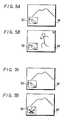
- Figure 2Ashows a case in which only the main picture screen (real moving picture) M is displayed on the picture screen of the cathode ray tube 18.
- a channel numberfor example "14"
- the numbers of the external video (identification) signal input terminals V1, V2 and V3would similarly be displayed as "V1", "V2" and "V3", by way of example.
- Figure 2Bshows a case in which a step-by-step picture composed of sub-picture screens S1, S2 and S3 of three still pictures is displayed on the main picture screen (real moving picture) M at its left-hand side in the up and down direction.
- the recall key 34 on the remote controller 24is depressed, the channel number "14" is displayed in green only on the main picture screen M and not on the sub-picture screens S1, S2, or S3.
- Figure 2Cshows a case in which a sub-picture screen (real moving picture) S1 is inset into the main picture screen (real moving picture) M at its lower left-hand corner.
- the recall key 34 on the remote controller 24is depressed, the channel number "14" is displayed in green on the upper right-hand corner of the main picture screen M and a channel number, for example "22", is displayed in white on the upper right-hand corner of the sub-picture screen S1.
- Figure 2Dshows a case in which a real moving picture S1 and step-by-step still pictures S2, S3 and S4, taken at different times from the real moving picture signal displayed on the screen S1, are each displayed on a separate sub-picture screen inset into, for example, the four corners of the main picture screen (real moving picture) M.
- the recall key 34 of the remote controller 24is depressed, the channel number "14" is displayed in green on the upper right-hand corner of the main picture screen M and a channel number "22" is displayed in white on the upper right-hand corner of each of the four sub-picture screens S1 to S4.
- the picture discrimination indications of the main picture and the sub-picture screenscan be positively discriminated from each other as required during and after changes in the display.
- the picture discrimination indicationsare carried out on both of the main and sub-picture screens.
- the television receiverwill be operated, under the control of the system control circuit 20, in accordance with a flow chart shown in Figure 4.
- the system control circuit 20causes the video blanking operations of the main and sub-picture screens to be carried out at a step 2.
- the video blankingsare carried out by, for example, the main and sub-picture/chroma signal circuits 8M and 8S, respectively.
- a picture of the video signal from the main tuner 5Mis displayed on the main picture screen and the main reception channel is moved in the up or down direction to reset the channel selection data - phase locked loop (PLL) data - of the main tuner 5M.
- PLLphase locked loop
- the change-over switch data of the main switching circuit 7Mis set in response to the incremented or decremented number of the external video signal input terminal whereby the main switching circuit 7M is switched so as to generate the video signal of the external video signal input terminal of the incremented or decremented number.
- the picture discriminator indication data of the main picture screenis set at a step 4. This picture discrimination indication data is supplied by the system control circuit 20 to the main character display circuit 19M which generates the main picture discrimination indication signal.
- the picture discrimination indication data of the sub-picture screenis set at a step 5.
- This picture discrimination indication datais supplied by the system control circuit 20 to the sub-character display circuit 195 which generates the sub-picture discrimination indication signal.
- the video blankingis released.
- the main picture, whose picture content has been changed,is then displayed on the main picture screen along with the sub-picture whose picture content has not been changed.
- the main and sub-picture discrimination indicationsare carried out on both the main and the sub-picture screens, respectively.
- the picture discrimination indicationswill be erased after, for example, 2 seconds, at a step 7.
- FIGs 5A and 5BThis sequence is illustrated in Figures 5A and 5B.
- the picture contentsare displayed on the main and sub-picture screens M and S1 before the main picture channel selection up key 36, for example, is depressed. If the up key 36 is then depressed, the picture content displayed on the main picture screen M is changed and new picture discrimination indications are displayed on both the main and sub-picture screens M and S1, as shown in Figure 5B. These picture discrimination indications are erased after 2 seconds.
- the picture discrimination indicationis carried out only on the sub-picture screen. That is, at that time, the television receiver is operated in accordance with a flow chart shown in Figure 6 under the control of the system control circuit 20.
- the up or down key 38is depressed at a step 10. Then, at a step 20, when the picture of the video signal from the sub-tuner 5S is displayed on the sub-picture screen S1 and the sub-reception channel is incremented or decremented, the system control circuit 20 causes the channel selection data of the sub-tuner 5S to be set in response to the incremented or decremented reception channel, whereby the sub- tuner 5S is placed in the channel selection mode for selecting the incremented or decremented reception channel.
- the switching data for changing-over the sub-switching circuit 7Sis set in response to the number of the incremented or decremented external video signal input terminal, whereby the sub-switching circuit 7S is switched so as to generate the video signal of the external video signal input terminal corresponding to the incremented or decremented number.
- the picture discrimination indication data of the sub picture screenis set at a step 30.
- this picture discrimination indication datais applied to the sub-character display circuit 19S in which the sub-picture screen discrimination indication signal is generated.
- the sub-picture whose picture content is changedis displayed on the sub-picture screen and the corresponding picture discrimination indication of the sub-picture is displayed on this sub-picture screen.
- a main picture having the same picture content as that of the original main pictureis displayed on the main picture screen.
- the picture discrimination indication on the sub-picture screenis erased after, for example, 2 seconds.
- a television receivercomprising a cathode ray tube, a composing circuit for composing a video signal for a main picture screen of the cathode ray tube type and a video signal for a sub-picture screen which is inset into a part of the main picture screen, a first adder for adding a picture discrimination indication signal to the video signal for the main picture screen, a second adder for adding a picture discrimination indication signal to the video signal for the sub-picture screen, and a system control circuit for controlling the composing circuit and the additions carried out by the first and second adders.
Landscapes
- Engineering & Computer Science (AREA)
- Multimedia (AREA)
- Signal Processing (AREA)
- Studio Circuits (AREA)
Description
- This invention relates to television receivers.
- A so-called picture-in-picture television receiver, in which a sub-picture screen is provided within a main picture screen such that pictures having different contents can be displayed on the main and sub-picture screens, respectively, in a picture-in-picture fashion, has been previously proposed. In this television receiver, television channels of the main picture and of the sub-picture, or the number of an external video signal input terminal, are displayed on a front panel of the television receiver using a display apparatus such as a light emitting diode (LED) display apparatus or the like, Alternatively, these numbers are displayed on the picture screen of the cathode ray tube. When these numbers, which are referred to herein as discrimination indications or picture discrimination indications, are displayed on the screen, they are displayed on the main picture screen together.
- The picture-in-picture television receiver is provided with a main tuner for selecting a video signal for the main picture screen and a sub-tuner for selecting a video signal for the sub-picture screen. In such a television receiver, it is preferable that the channel selection operations can be carried out independently in the main and sub-tuners. Thus, the discrimination indications of the picture contents, for example the indications of the channels selected, are independently carried out on the main and sub-picture screens in response to the respective channel selection operations.
- However, in the previously proposed picture-in-picture television receiver, the picture discrimination indications for discriminating the main picture screen and the sub-picture screen cannot be positively carried out. There is no problem when the selected channel of the sub-tuner is changed, in that the change in the discrimination indication of the picture content is carried out only on the sub-picture screen. However, when the selected channel of the main tuner is changed, a problem arises in that the picture discrimination indication for the picture content is carried out only on the main picture screen. That is, since it is apt to be regarded that the picture displayed on the sub-picture screen is subjected to the picture displayed on the main picture screen, it would be preferable in this case for the discrimination indication for the picture content to be carried out also on the sub-picture screen.
- Patent Abstracts of Japan,
Volume 5, Number 78, (E-58) [750], 22nd May 1981 of JP-A-56 027 573 discloses a picture-in-picture type television receiver without channel indication. GB-A-2,132,842 discloses a single picture type television receiver in which a channel indication number is displayed upon the screen. - According to the invention there is provided a television receiver comprising:
- (a) a cathode ray tube having a picture screen which is divisible into a main picture screen and one or more sub-picture screens inset into the main picture screen;
- (b) a main picture circuit for selecting a first video signal from a plurality of video signals and supplying the selected video signal as a video signal for the main picture screen;
- (c) a sub-picture circuit for selecting a second video signal from a plurality of video signals and supplying the selected video signal as a sub-picture video signal for one or more of the sub-picture screens; and
- (d) a composing circuit for composing the selected video signal for the main picture screen of the cathode ray tube and the selected video signal for the sub-picture screen into a composite signal to be supplied to the cathode ray tube; characterised by
- (e) a first adder at a point in the transmission path between the composing circuit and the cathode ray tube for adding a picture discrimination indication signal to the video signal for the main picture screen;
- (f) a second adder at a point in the transmission path between the sub-picture circuit and the composing circuit for adding a picture discrimination indication signal to the video signal for the sub-picture screen; and
- (g) a system control circuit for controlling the main picture circuit, the sub-picture circuit, the composing circuit, the first adder and the second adder such that the sub-picture discrimination indication signal is displayed on the sub-picture screen whenever the sub-picture circuit selects a different one of the plurality of video signals as the second video signal.
- In a picture-in-picture television receiver in accordance with a preferred embodiment of the invention, as described in detail hereinbelow, picture discrimination indications of the main picture screen and the sub-picture screen can be positively discriminated from each other as required. Whenever the content of the picture displayed on the main picture screen in changed, the change in the discrimination indication of the picture content is displayed on the main picture screen and the discrimination indication of the unchanged sub-picture screen is also simultaneously displayed. The preferred picture-in-picture television receiver can be used by the user more conveniently and usefully.
- The invention will now be further described, by way of illustrative and non-limiting example, with reference to the accompanying drawings, in which like references designate like elements and parts throughout, and in which:
- Figure 1 is a block diagram of a television receiver in accordance with a preferred embodiment of the present invention;
- Figures 2A to 2D and 3A to 3I are respective diagrams used to explain how picture discrimination indications are superimposed on main and sub-picture screens of the television receiver;
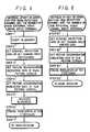
- Figure 4 is a flow chart used to explain an operation in which, when the content of a picture displayed on the main picture screen is changed, picture discrimination indications are carried out for both the main and sub-picture screens;
- Figure 5A and 5B are schematic diagrams used to explain the operation carried out in accordance with the flow chart shown in Figure 4;
- Figure 6 is a flow chart used to explain an operation in which, when the content of a picture displayed on the sub -picture screen is changed, picture discrimination indication is carried out only for the sub-picture screen; and
- Figures 7A and 7B are schematic diagrams used to explain the operation carried out in accordance with the flow chart shown in Figure 6.
- Figure 1 is a block diagram showing an overall circuit arrangement of a television receiver embodying the present invention. The television receiver includes a main television circuit MK and a sub-television circuit SK. A video signal supplied by the main television circuit MK causes a main picture to be displayed on the whole of a picture screen of a
cathode ray tube 18, whereas a video signal supplied by the sub-television circuit SK causes a sub-picture to be displayed on a portion of the main picture screen in such a manner that the sub-picture is inset into the main picture. The main and sub-television circuits MK and SK include main andsub-tuners 5M, 55, main and sub-videointermediate frequency circuits chroma signal circuits - The television receiver is provided with external video signal input terminals V1, V2 and V3 to which reproduced video signals (base band signals) from a video tape recorder (VTR) or the like can be supplied. Selection of the video signals from the external input terminals V1, V2 and V3, in place of the video signals from the
tuners sub-switching circuits switching circuit 7M is then supplied to thecathode ray tube 18 to be displayed on its picture screen. - The sub-television circuit SK includes a video
signal processor circuit 12 for displaying the sub-picture on the picture screen of thecathode ray tube 18. The videosignal processor circuit 12 controls the kinds of sub-picture or sub-pictures (such as a live picture, a still picture, a step-by-step picture or the like), the number of sub-pictures, the position of the sub-picture on the main picture screen, and so forth. The expression "live picture" means that the displayed image is animated (moving) rather than static (still). - The main and sub-television circuits MK and SK are provided with respective main and
sub-character display circuits discriminating indications 32M, 32S, respectively, on the main picture screen and the sub-picture screen, respectively, in an inset fashion as shown in Figure 2C. Eachindication 32M, 32S may, for example, comprise the channel identification (for instance the channel number) of a received television broadcast or the number of an external video signal input terminal. - The television receiver includes a system control circuit or
controller 20 which includes a microcomputer. Respective sections of the television receiver are controlled by thesystem control circuit 20 as will be explained in greater detail hereinafter. - The circuit arrangement of the television receiver will now be described more fully. A television broadcast signal received by an aerial (antenna) AT is supplied to a
distributor 1. Thedistributor 1 supplies the received signal through aswitching circuit 3 to themain tuner 5M, without substantially attenuating the signal, and also supplies a portion of the received signal to thesub-tuner 5S. The received signal portion is amplified by ahigh frequency amplifier 4 before it is applied to thesub-tuner 5S. Theswitching circuit 3 selectively switches between the aerial input signal from thedistributor 1, and a high frequency input signal from a descrambler used for receiving a cable television broadcast or the like and supplied to anauxiliary input terminal 2, and supplies one of the signals to themain tuner 5M. - The video signal from the
main tuner 5M is supplied to the main videointermediate frequency circuit 6M and a video intermediate frequency signal is supplied therefrom to themain switching circuit 7M which can be selectively switched between this video signal and the external video signals from the external video input terminals V1 to V3. The signal selected by theswitching circuit 7M is supplied to the main video/chroma signal circuit 8M. Amonitor output terminal 26 is connected to the output side of themain switching circuit 7M. The main video/chroma signal circuit 8M generates red, green and blue colour signals R, G and B which are fed to a switching circuit 9. - An audio intermediate frequency signal from the main video
intermediate frequency circuit 6M is supplied to an audio circuit (incorporating a sound multiplexing decoder circuit) 28. An audio signal from theaudio circuit 28 is supplied to aswitching circuit 29 which can be selectively switched between this audio signal and external audio signals reproduced from a VTR or the like and supplied thereto from external audio signal input terminals A1, A2 and A3, respectively, corresponding to the external video signal input terminals V1, V2 and V3. The audio signal selected by theswitching circuit 29 is supplied through alow frequency amplifier 30 to aloudspeaker 31. - Horizontal and vertical synchronising signals from the main video/
chroma signal circuit 8M are supplied to a deflection/high voltage circuit 27. A deflection signal and a highdc voltage from thecircuit 27 are supplied to thecathode ray tube 18. - The video signal from the
sub-tuner 5S is supplied to the sub-videointermediate frequency circuit 6S and a video intermediate frequency signal is supplied therefrom to thesub-switching circuit 7S which selectively switches between this video signal and the external video signals from the external video signal input terminals V1 to V3. Aswitch 25 effects selection between the video signal selected by theswitching circuit 7S and the video signal from themain switching circuit 7M and supplies the chosen video signal to the sub-video/chroma signal circuit 8S. The sub -video/chroma signal circuit 8S generates red, green and blue colour signals R, G and B which are supplied to amatrix circuit 10 in which they are converted to a luminance signal Y and red and blue colour difference signals R-Y and B-Y, respectively, which are then fed to an analog-to-digital (A/D)converter 13 in the videosignal processor circuit 12. - The A/
D converter 13 is a time division type A/D converter as disclosed, for example, in Japanese Patent Application Publication JP-A-60-47792. A digital signal from the A/D converter 13 is supplied to amemory 14 and written therein. The digital signal is read out from thememory 14 and supplied to a digital-to-analog (D/A)converter 15 so as thereby to be converted to an analog signal. In the videosignal processor circuit 12, sampling lines and picture elements of the video signal are selected and other lines and picture elements are thrown away or removed in correspondence with the ratio between the sizes of the main picture screen and the sub-picture screen. Thememory 14 has frame (or field) memory areas corresponding to the maximum number of displayable sub -pictures, for example four frame memory areas. Thememory 14 is controlled by asub-picture control circuit 16 so as to specify the kinds of sub-picture of sub-pictures (such as a live picture, a still picture, a step-by-step picture and so on), the number of sub-pictures, the position of the sub-picture on the main picture and the like. - When the sub-picture is displayed as a live picture, that is a real moving picture, the video signal is alternately written in and read out from the
memory 14 continuously and repeatedly; when the sub-picture is displayed as a still picture, the video signal is written in thememory 14 for a selected frame or field period and then read out from thememory 14 repeatedly; and when the sub-picture is displayed as a step-by-step picture, a plurality of video signals are written in thememory 14 at different times corresponding to different frames or field periods and then read out therefrom repeatedly (see Japanese Patent Application Publication JP-A-56-27573). The number of the sub-picture screens inset into the main picture screen is determined on the basis of the number of memory areas in thememory 14 which are used. The contents or picture of the sub-picture screen can be a real moving picture, a still picture or a step-by-step picture based on the video signal from the sub-video/chroma signal circuit 8S or on the video signal from the main video/chroma signal circuit 8M. The switching of these video signals is carried out by theswitch 25. The picture contents on the main picture screen and the sub-picture screen can be exchanged with each other by simultaneously switching the reception channels of the main and sub-tuners 5M and 5S or by simultaneously switching the main andsub-switching circuits - The respective colour signals from the main/video
chroma signal circuit 8M and the respective colour signals from the D/A converter 15 are supplied to the switching circuit 9 in which both groups of respective colour signals are switched at appropriate timing intervals such that the sub-picture screen is inset into one portion of the main picture screen at a selected, predetermined position. The switching circuit 9 is controlled by thesub-picture control circuit 16, which is controlled by thesystem control circuit 20. The video signal from the switching circuit 9 is supplied to thecathode ray tube 18. - The main picture discrimination indicating signal, such as a signal indicative of the main channel number, is formed by the main
character display circuit 19M and is added to the video signal by anadder 17 connected between the switching circuit 9 and thecathode ray tube 18. In this example, theadder 17 is interposed only in the transmission path of the green colour signal G to thereby superimpose a green picture discrimination indication upon the main picture screen. It is of course possible for this picture discrimination indication to be made by using other colours. - The sub-picture discrimination indicating signal, which is formed by the
sub-character display circuit 19S and which could be indicative of the channel number selected by the sub-tuner 5S, for example, is added to the sub-video signal by an adder 11 connected between thematrix circuit 10 and the A/D converter 13. In this example, the adder 11 is interposed only in the transmission path of the luminance signal Y to thereby superimpose a white picture discrimination indication on the sub-picture screen. However, it is possible for this picture discrimination indication to be made by using other colours. - Channel selections in the
main tuner 5M and sub-tuner 5S are carried out by channel selection signals from thesystem control circuit 20. The switchingcircuits switch 25 are also selectively switched under the control of thesystem control circuit 20. The main and sub-video/chroma signal circuits system control circuit 20 for a short period upon up and down scanning channel selection operation. Alternatively, such blanking may be carried out by a blanking switch that is provided at a stage before thecathode ray tube 18. Further, main and sub-horizontal synchronising signals Hm and Ms from the main and sub-videointermediate frequency circuits chroma signal circuits system control circuit 20. The main picture and sub-picture discrimination indicatingsignal circuits sub-picture control circuit 16 are controlled by thesystem control circuit 20. - A last-
condition memory 21 stores, under the control of thesystem control circuit 20, the selected channels of the main and sub-tuners 5M and 5S, the switch conditions of the switchingcircuits sub-picture control circuit 16 and so on when power to the television receiver is turned off. When the television receiver is turned on again, the conditions of the respective circuits present when the television receiver was last turned off are reproduced under the control of thesystem control circuit 20. - A
key apparatus 22 is connected to thesystem control circuit 20 and is provided with various kinds of keys KY to control the television receiver. - A remote controller (commander) 24 also is provided with various kinds of keys KY to control the television receiver. The
remote controller 24 is also provided with a transmitter (not shown) to transmit a remote control signal based on the corresponding key operation. Areceiver 23 for receiving the signal transmitted from the transmitter of theremote controller 24 is connected to thesystem control circuit 20. The remote control signal can be transmitted by means of a light beam, radio wave, sound wave and so on. - By way of example, the keys KY of the
key apparatus 22 or theremote controller 24 may comprise: apower key 33; a recall key 34 (used to display the picture discrimination indication such as the channel number); a mute key (used to mute the sound); ten keys (designated generally by the reference numeral 35) used to select the reception channel and the number of the external video signal input terminal; a TV (television)/VTR change-over key; an aerial input/auxiliary high frequency input change-over key; a sound multiplexing key; up and downkeys 36 for incrementing and decrementing the contrast of luminance and chrominance signals, the main reception channels, the number of the main external video signal input terminal, and the sound volume, respectively; an on-off key 37 for the sub-picture screen; up and downkeys 38 for incrementing and decrementing the sub-reception channel and the number of the sub-external video signal input terminal; a still picture key; a step-by-step picture key; a shift key used to shift the position of the sub-picture screen; and a main-sub exchange key 39 used to exchange the picture contents on the main picture and sub -picture screens. - How to superimpose the picture discrimination indications on the respective picture screens will now be described with reference to Figures 2A to 2D and 3A to 3I.
- Figure 2A shows a case in which only the main picture screen (real moving picture) M is displayed on the picture screen of the
cathode ray tube 18. In this case, when therecall key 34 on theremote controller 24 is depressed, a channel number, for example "14", is displayed in green on the main picture screen M at, for example, the upper right-hand corner of the screen, as a picture discrimination indication. The numbers of the external video (identification) signal input terminals V1, V2 and V3 would similarly be displayed as "V1", "V2" and "V3", by way of example. - Figure 2B shows a case in which a step-by-step picture composed of sub-picture screens S₁, S₂ and S₃ of three still pictures is displayed on the main picture screen (real moving picture) M at its left-hand side in the up and down direction. In this case, when the
recall key 34 on theremote controller 24 is depressed, the channel number "14" is displayed in green only on the main picture screen M and not on the sub-picture screens S₁, S₂, or S₃. - Figure 2C shows a case in which a sub-picture screen (real moving picture) S₁ is inset into the main picture screen (real moving picture) M at its lower left-hand corner. In this case, when the
recall key 34 on theremote controller 24 is depressed, the channel number "14" is displayed in green on the upper right-hand corner of the main picture screen M and a channel number, for example "22", is displayed in white on the upper right-hand corner of the sub-picture screen S₁. - Figure 2D shows a case in which a real moving picture S₁ and step-by-step still pictures S₂, S₃ and S₄, taken at different times from the real moving picture signal displayed on the screen S₁, are each displayed on a separate sub-picture screen inset into, for example, the four corners of the main picture screen (real moving picture) M. In this case, when the
recall key 34 of theremote controller 24 is depressed, the channel number "14" is displayed in green on the upper right-hand corner of the main picture screen M and a channel number "22" is displayed in white on the upper right-hand corner of each of the four sub-picture screens S₁ to S₄. - The display operation of the television receiver will now be described more fully with reference to Figures 3A to 3I.
- When only the main picture screen M (real moving picture) is displayed as shown in Figure 3A, if the on-
off key 37 of theremote controller 24 for the sub-picture screen is depressed, the sub-picture screen S₁ (real moving picture) is displayed as shown in Figure 3B. At that time, the channel number "22" is displayed in white on the upper right-hand corner of the sub-picture screen S₁ for a time period of, for example, 2 seconds, and then the indication of the channel number "22" disappears, as shown in Figure 3C. - When the main picture screen M (real moving picture) and the sub-picture screen S₁ (real moving picture of the channel 22) are both displayed, as shown in Figure 3D, if the up key or down
key 38 of the sub-reception channel on theremote controller 24 is depressed, the picture on the sub-picture screen S₁ is changed and also a channel number, for example "10", thereof is displayed in white on the sub-picture screen S₁ for a time period of, for example, 2 seconds, as shown in Figure 3E. Thereafter, the indication of the channel number "10" disappears, as shown in Figure 3F. - When the main picture screen M (real moving picture of the channel 14) and the sub-picture screen S₁ (real moving picture of the channel 22) are both displayed, as shown in Figure 3G, if the main-sub exchange key 39 on the
remote controller 24 used to exchange the contents of the pictures on the main and sub-picture screens is depressed, the contents of the pictures on the main picture screen M and the sub-picture screen S₁ are exchanged, as shown in Figure 3H, and, also, the channel number "22" is displayed on the main picture screen M and the channel number "14" is displayed on the sub-picture screen S₁ for a time period of, for example, 2 seconds. Thereafter, the indications of the respective channel numbers "14" and "22" disappear, as shown in Figure 3I. - According to the arrangement described above, the picture discrimination indications of the main picture and the sub-picture screens can be positively discriminated from each other as required during and after changes in the display.
- The operation of the television receiver will now be described further.
- When the up key or down
key 36 of theremote controller 24 for incrementing or decrementing the main reception channel and the number of the main external video signal input terminal is depressed to thereby change the content of the picture displayed on the main picture screen, the picture discrimination indications are carried out on both of the main and sub-picture screens. At that time, the television receiver will be operated, under the control of thesystem control circuit 20, in accordance with a flow chart shown in Figure 4. - Referring to the flow chart shown in Figure 4, when the up key or down key is depressed at a
step 1, thesystem control circuit 20 causes the video blanking operations of the main and sub-picture screens to be carried out at astep 2. The video blankings are carried out by, for example, the main and sub-picture/chroma signal circuits step 3, a picture of the video signal from themain tuner 5M is displayed on the main picture screen and the main reception channel is moved in the up or down direction to reset the channel selection data - phase locked loop (PLL) data - of themain tuner 5M. Also at thestep 3, when the picture of a video signal from the external video signal input terminals V1 to V3 is displayed on the main picture screen and the number of the external video signal input terminal is moved upwardly or downwardly, the change-over switch data of themain switching circuit 7M is set in response to the incremented or decremented number of the external video signal input terminal whereby themain switching circuit 7M is switched so as to generate the video signal of the external video signal input terminal of the incremented or decremented number. Then, the picture discriminator indication data of the main picture screen is set at astep 4. This picture discrimination indication data is supplied by thesystem control circuit 20 to the maincharacter display circuit 19M which generates the main picture discrimination indication signal. Subsequently, the picture discrimination indication data of the sub-picture screen is set at astep 5. This picture discrimination indication data is supplied by thesystem control circuit 20 to the sub-character display circuit 195 which generates the sub-picture discrimination indication signal. At astep 6, the video blanking is released. The main picture, whose picture content has been changed, is then displayed on the main picture screen along with the sub-picture whose picture content has not been changed. In this case, the main and sub-picture discrimination indications are carried out on both the main and the sub-picture screens, respectively. The picture discrimination indications will be erased after, for example, 2 seconds, at astep 7. - This sequence is illustrated in Figures 5A and 5B. In Figure 5A, the picture contents are displayed on the main and sub-picture screens M and S₁ before the main picture channel selection up key 36, for example, is depressed. If the up key 36 is then depressed, the picture content displayed on the main picture screen M is changed and new picture discrimination indications are displayed on both the main and sub-picture screens M and S₁, as shown in Figure 5B. These picture discrimination indications are erased after 2 seconds.
- Further, in this embodiment, when the up key or down
key 38 of, for example, theremote controller 24 is depressed to increment or decrement the sub-reception channel or the number of the sub-external video signal input terminal and hence the picture content displayed on the sub-picture screen is changed, the picture discrimination indication is carried out only on the sub-picture screen. That is, at that time, the television receiver is operated in accordance with a flow chart shown in Figure 6 under the control of thesystem control circuit 20. - Referring to the flow chart shown in Figure 6, the up or down key 38 is depressed at a
step 10. Then, at astep 20, when the picture of the video signal from the sub-tuner 5S is displayed on the sub-picture screen S₁ and the sub-reception channel is incremented or decremented, thesystem control circuit 20 causes the channel selection data of the sub-tuner 5S to be set in response to the incremented or decremented reception channel, whereby the sub-tuner 5S is placed in the channel selection mode for selecting the incremented or decremented reception channel. If, however, at thestep 20, a picture provided by a video signal from the external video signal input terminals V1 to V3 is displayed on the sub-picture screen S₁ and the number of the external video signal input terminal is incremented or decremented, the switching data for changing-over thesub-switching circuit 7S is set in response to the number of the incremented or decremented external video signal input terminal, whereby thesub-switching circuit 7S is switched so as to generate the video signal of the external video signal input terminal corresponding to the incremented or decremented number. Then, the picture discrimination indication data of the sub picture screen is set at astep 30. So, this picture discrimination indication data is applied to thesub-character display circuit 19S in which the sub-picture screen discrimination indication signal is generated. By virtue of the operations represented at thesteps step 40, the picture discrimination indication on the sub-picture screen is erased after, for example, 2 seconds. - For example, when the picture contents shown in Figure 7A are displayed on the main and sub-picture screens M and S₁ before the up key 38 is depressed, if the up key 38 is depressed, the picture discrimination indication is carried out only on the sub-picture screen S₁, which is changed as shown in Figure 7b. Then, this picture discrimination indication is erased after 2 seconds.
- According to the above-described embodiment of the present invention, when the picture content displayed on the main picture screen is changed, not only is the corresponding picture discrimination indication displayed on the main picture screen, but also the picture discrimination indication is displayed on the sub-picture screen. Accordingly, positive confirmation is provided to the user that the picture content displayed on the sub-picture screen remains unchanged.
- It will be seen that the described embodiment in overall terms provides a television receiver comprising a cathode ray tube, a composing circuit for composing a video signal for a main picture screen of the cathode ray tube type and a video signal for a sub-picture screen which is inset into a part of the main picture screen, a first adder for adding a picture discrimination indication signal to the video signal for the main picture screen, a second adder for adding a picture discrimination indication signal to the video signal for the sub-picture screen, and a system control circuit for controlling the composing circuit and the additions carried out by the first and second adders.
Claims (12)
- A television receiver comprising:(a) a cathode ray tube (18) having a picture screen which is divisible into a main picture screen (M) and one or more sub-picture screens (S₁) inset into the main picture screen (M);(b) a main picture circuit (7M, 8M) for selecting a first video signal from a plurality of video signals (V₁, V₂, V₃, 5M) and supplying the selected video signal as a video signal for the main picture screen (M);(c) a sub-picture circuit (7S, 25, 8S) for selecting a second video signal from a plurality of video signals (V₁, V₂, V₃, 5S) and supplying the selected video signal as a sub-picture video signal for one or more of the sub-picture screens (S₁); and(d) a composing circuit (9) for composing the selected video signal for the main picture screen (M) of the cathode ray tube (18) and the selected video signal for the sub-picture screen (S₁) into a composite signal (R,G,B) to be supplied to the cathode ray tube (18); characterised by(e) a first adder (19M, 17) at a point in the transmission path between the composing circuit (9) and the cathode ray tube (18) for adding a picture discrimination indication signal to the video signal for the main picture screen (M);(f) a second adder (19S, 11) at a point in the transmission path between the sub-picture circuit (7S, 25, 8S) and the composing circuit (9) for adding a picture discrimination indication signal to the video signal for the sub-picture screen (S₁); and(g) a system control circuit (20) for controlling the main picture circuit (7M, 8M), the sub-picture circuit (7S, 25, 8S), the composing circuit (9), the first adder (19M, 17) and the second adder (19S, 11) such that the sub-picture discrimination indication signal is displayed on the sub-picture screen (S₁) whenever the sub-picture circuit (7S, 25, 8S) selects a different one of the plurality of video signals (V₁, V₂, V₃, 5S) as the second video signal.
- A television receiver according to claim 1, comprising a recall key (34) for the picture discrimination indication, the system control circuit (20) being operative to control the adders (19M, 17, 19S, 11) such that, if the recall key (34) is operated when only the main picture screen (M) is displayed on the cathode ray tube (18), the discrimination indication of the picture is displayed on the main picture screen (M).
- A television receiver according to claim 2, wherein the system control circuit (20) is operative to control the adders (19M, 17, 19S, 11) such that, if the recall key (34) is operated when the main picture screen (M) and a plurality of sub-picture screens (S₁, S₂, S₃) whose picture contents are the same as that of the main picture screen (M) but taken at different times from the main picture screen (M) are displayed, only the discrimination indication of the picture on the main picture screen (M) is displayed.
- A television receiver according to claim 2 or claim 3, wherein the system control circuit (20) is operative to control the adders (19M, 17, 19S, 11) such that, if the recall key (34) is operated when the main picture screen (M) and the sub-picture screen (S₁) are displaying pictures from different signals, the discrimination indications of the pictures on the main and sub-picture screens (M, S₁) are displayed thereon, respectively.
- A television receiver according to claim 2, claim 3 or claim 4, wherein the system control circuit (20) is operative to control the adders (19M, 17, 19S, 11) such that, if the recall key (34) is operated when the main picture screen (M) is displaying a picture different from pictures displayed on a plurality of sub-picture screens (S₁,etc,), the discrimination indications of the pictures on the main picture screen (M) and the plurality of sub-picture screens (S₁, etc.) are displayed on the respective screens.
- A television receiver according to any one of the preceding claims, comprising an on/off key (37) for the sub-picture screen (S₁), the system control circuit (20) being operative to control the adders (19M, 17, 19S, 11) such that, if the on/off key (37) is operated when only the main picture screen (M) is displayed, the sub-picture screen (S₁) is displayed and, at the same time, a discrimination indication of the sub-picture screen (S₁) is displayed thereon for a predetermined period of time.
- A television receiver according to any one of the preceding claims comprising an exchange key (39) for exchanging the pictures between the main and sub-picture screens (M, S₁) the system control circuit (20) being operative to control the adders (19M, 17, 19S,11) such that, if the exchange key (39) is operated when different pictures are produced on the main and sub-picture screens (M, S₁), the pictures of the main and sub-picture screens are exchanged with each other and the discrimination indications of the main and sub-picture screens are respectively disPlayed thereon for a predetermined period of time.
- A television receiver according to any one of claims 1 to 7, comprising a channel up/down key (38) for changing the sub-channel of the sub-picture screen (S₁), the system control circuit (20) being operative to control the adders (19M, 17, 19S, 11) such that, if the channel up/down key (38) is operated when the main picture screen (M) is displaying a picture different from that displayed on the sub-picture screen (S₁), the picture of the sub-picture screen (S₁) is changed and, at the same time, a discrimination indication of the sub-picture screen (S₁) is displayed thereon for a predetermined period of time.
- A television receiver according to any one of claims 1 to 7, comprising channel selection keys (35, 38) for the main and sub-pictures, the system control circuit (20) being operative to control the adders (19M, 17, 19S, 11) such that, if the channel selection key (35) for the main picture is operated when different pictures are produced on the ain and sub-picture screens (M, S₁), the picture on the main picture screen (M) is changed and, at the same time, the discrimination indications of the main and sub-picture screens (M, S₁) are respectively displayed thereon for a predetermined period of time.
- A television receiver according to claim 9, wherein the system control circuit (20) is operative to control the adders (19M, 17,19S, 11) such that, if the channel selection key (38) for the sub-picture is operated when different pictures are produced on the main and sub-picture screens (M, S₁), the picture on the sub-picture screen (S₁) is changed and, at the same time, the discrimination indication of the sub-picture screen (S₁) is displayed thereon for a predetermined period of time.
- A television receiver according to claim 10, wherein the system control circuit (20) is operative to control the adders (19M, 17, 19S, 11) such that, if the channel selection key (38) for the sub-picture is further operated, the picture of the sub-picture screen (S₁) is changed and, at the same time, only the discrimination indication of the sub-picture screen (S₁) is displayed for a predetermined period of time.
- A television receiver as claimed in claim 1, wherein the picture discrimination indication signal for the main picture screen (M) is added to one colour component of the composite signal (R, G, B) and the picture discrimination indication signal for the sub-picture screen (S₁) is added to the luminance component of the sub-picture video signal.
Applications Claiming Priority (4)
| Application Number | Priority Date | Filing Date | Title |
|---|---|---|---|
| JP297328/85 | 1985-12-28 | ||
| JP60297328AJP2534985B2 (en) | 1985-12-28 | 1985-12-28 | Television receiver |
| JP164386AJPH0746847B2 (en) | 1986-01-08 | 1986-01-08 | Television receiver |
| JP1643/86 | 1986-01-08 |
Publications (3)
| Publication Number | Publication Date |
|---|---|
| EP0229526A2 EP0229526A2 (en) | 1987-07-22 |
| EP0229526A3 EP0229526A3 (en) | 1989-02-01 |
| EP0229526B1true EP0229526B1 (en) | 1993-03-03 |
Family
ID=26334907
Family Applications (1)
| Application Number | Title | Priority Date | Filing Date |
|---|---|---|---|
| EP86310158AExpired - LifetimeEP0229526B1 (en) | 1985-12-28 | 1986-12-24 | Picture-in-picture television receivers |
Country Status (7)
| Country | Link |
|---|---|
| US (1) | US4746983A (en) |
| EP (1) | EP0229526B1 (en) |
| KR (1) | KR940005221B1 (en) |
| AU (1) | AU591743B2 (en) |
| CA (1) | CA1256984A (en) |
| DE (1) | DE3687897T2 (en) |
| HK (1) | HK95395A (en) |
Cited By (8)
| Publication number | Priority date | Publication date | Assignee | Title |
|---|---|---|---|---|
| US7996864B2 (en) | 1994-08-31 | 2011-08-09 | Gemstar Development Corporation | Method and apparatus for displaying television programs and related text |
| US8336071B2 (en) | 1996-12-19 | 2012-12-18 | Gemstar Development Corporation | System and method for modifying advertisement responsive to EPG information |
| US8776125B2 (en) | 1996-05-03 | 2014-07-08 | Starsight Telecast Inc. | Method and system for displaying advertisements in an electronic program guide |
| US8832742B2 (en) | 2006-10-06 | 2014-09-09 | United Video Properties, Inc. | Systems and methods for acquiring, categorizing and delivering media in interactive media guidance applications |
| US8918807B2 (en) | 1997-07-21 | 2014-12-23 | Gemstar Development Corporation | System and method for modifying advertisement responsive to EPG information |
| US9015750B2 (en) | 1998-05-15 | 2015-04-21 | Rovi Guides, Inc. | Interactive television program guide system for determining user values for demographic categories |
| US9319735B2 (en) | 1995-06-07 | 2016-04-19 | Rovi Guides, Inc. | Electronic television program guide schedule system and method with data feed access |
| US9426509B2 (en) | 1998-08-21 | 2016-08-23 | Rovi Guides, Inc. | Client-server electronic program guide |
Families Citing this family (65)
| Publication number | Priority date | Publication date | Assignee | Title |
|---|---|---|---|---|
| US4857994A (en)* | 1984-04-09 | 1989-08-15 | Corporate Communications Consultants, Inc. | Color correction system and method |
| JPH0638652B2 (en)* | 1985-12-28 | 1994-05-18 | ソニー株式会社 | Television receiver |
| JP2794661B2 (en)* | 1986-09-20 | 1998-09-10 | ソニー株式会社 | TV receiver |
| US4918526A (en)* | 1987-03-20 | 1990-04-17 | Digital Equipment Corporation | Apparatus and method for video signal image processing under control of a data processing system |
| JP2698105B2 (en)* | 1987-07-28 | 1998-01-19 | 三洋電機株式会社 | Digital television receiver |
| US4855813A (en)* | 1987-12-11 | 1989-08-08 | Russell David P | Television image processing system having capture, merge and display capability |
| KR910001515B1 (en)* | 1987-12-30 | 1991-03-09 | 삼성전자 주식회사 | Card character screen generation circuit of TV and VTR |
| EP0639025B1 (en)* | 1988-01-08 | 2000-04-12 | Fuji Photo Film Co., Ltd. | Color film analyzing apparatus |
| JPH01246978A (en)* | 1988-03-28 | 1989-10-02 | Toshiba Corp | Image information reception display device |
| KR910004274B1 (en)* | 1988-04-16 | 1991-06-25 | 삼성전자 주식회사 | Multi screen control circuit on picture in picture tv |
| NL8801413A (en)* | 1988-06-02 | 1990-01-02 | Philips Nv | TV-RECEIVER. |
| JPH0219079A (en)* | 1988-07-06 | 1990-01-23 | Pioneer Electron Corp | Video signal processing unit |
| DE3831754A1 (en)* | 1988-09-19 | 1990-03-29 | Grundig Emv | ARRANGEMENT FOR THE SIMULTANEOUS DISPLAY OF SEVERAL TELEVISION SIGNALS |
| US4959719A (en)* | 1988-12-21 | 1990-09-25 | North American Philips Corporation | Picture-in-picture television receiver control |
| US4903129A (en)* | 1989-04-06 | 1990-02-20 | Thomson Consumer Electronics, Inc. | Audio signal section apparatus |
| JP2906462B2 (en)* | 1989-07-18 | 1999-06-21 | ソニー株式会社 | Television receiver |
| NL192655C (en)* | 1989-07-26 | 1997-11-04 | Samsung Electronics Co Ltd | Multi-channel editing unit menu type. |
| NL192555C (en)* | 1989-08-28 | 1997-09-02 | Samsung Electronics Co Ltd | Television set-up with PIP mode. |
| US5258750A (en)* | 1989-09-21 | 1993-11-02 | New Media Graphics Corporation | Color synchronizer and windowing system for use in a video/graphics system |
| US5023720A (en)* | 1989-10-30 | 1991-06-11 | The Grass Valley Group, Inc. | Single channel video push effect |
| JPH05324821A (en)* | 1990-04-24 | 1993-12-10 | Sony Corp | High-resolution video and graphic display device |
| JP2765188B2 (en)* | 1990-05-28 | 1998-06-11 | 松下電器産業株式会社 | Signal processing circuit |
| GB9012326D0 (en)* | 1990-06-01 | 1990-07-18 | Thomson Consumer Electronics | Wide screen television |
| KR930006483B1 (en)* | 1991-06-24 | 1993-07-16 | 삼성전자 주식회사 | Picture in picture screen system having message data |
| KR930003720A (en)* | 1991-07-09 | 1993-02-24 | 강진구 | How to automatically discover PIP channels |
| JPH05236377A (en)* | 1992-02-18 | 1993-09-10 | Sony Corp | Video selector |
| JP3237791B2 (en)* | 1992-11-21 | 2001-12-10 | ソニー株式会社 | Video display device |
| US5563665A (en)* | 1993-12-29 | 1996-10-08 | Chang; Darwin | Video signal controller for use with a multi-sync monitor for displaying a plurality of different types of video signals |
| US5970205A (en)* | 1994-04-06 | 1999-10-19 | Sony Corporation | Method and apparatus for performing variable speed reproduction of compressed video data |
| US5508737A (en)* | 1994-07-06 | 1996-04-16 | Sony Corporation | Remote video viewing and recording system for remotely occurring events |
| US20050204384A1 (en)* | 1994-08-31 | 2005-09-15 | Gemstar Development Corporation | Method and apparatus for displaying television programs and related text |
| US5598208A (en)* | 1994-09-26 | 1997-01-28 | Sony Corporation | Video viewing and recording system |
| JPH08107543A (en)* | 1994-10-07 | 1996-04-23 | Sony Corp | Character display controller |
| CN1155235C (en)* | 1994-12-13 | 2004-06-23 | 杰姆斯达发展公司 | Apparatus and method for channel scanning according to theme |
| US5886746A (en)* | 1994-12-13 | 1999-03-23 | Gemstar Development Corporation | Method for channel scanning |
| JPH08307942A (en)* | 1995-05-02 | 1996-11-22 | Sony Corp | Cordless telephone set, electronic apparatus and program selecting method |
| US5808691A (en)* | 1995-12-12 | 1998-09-15 | Cirrus Logic, Inc. | Digital carrier synthesis synchronized to a reference signal that is asynchronous with respect to a digital sampling clock |
| US5986650A (en) | 1996-07-03 | 1999-11-16 | News America Publications, Inc. | Electronic television program guide schedule system and method with scan feature |
| US6097383A (en)* | 1997-01-23 | 2000-08-01 | Zenith Electronics Corporation | Video and audio functions in a web television |
| EP1439705A3 (en)* | 1997-03-17 | 2011-09-14 | Panasonic Corporation | Method and apparatus for processing, transmitting and receiving dynamic image data |
| US5995161A (en)* | 1997-04-02 | 1999-11-30 | Sony Corporation | Digital video processor with subvideo processor |
| US6028643A (en)* | 1997-09-03 | 2000-02-22 | Colorgraphic Communications Corporation | Multiple-screen video adapter with television tuner |
| US6429903B1 (en) | 1997-09-03 | 2002-08-06 | Colorgraphic Communications Corporation | Video adapter for supporting at least one television monitor |
| US6563515B1 (en) | 1998-05-19 | 2003-05-13 | United Video Properties, Inc. | Program guide system with video window browsing |
| US6661472B2 (en)* | 1998-09-30 | 2003-12-09 | Sony Corporation | Channel selection in digital television |
| WO2001001689A1 (en) | 1999-06-29 | 2001-01-04 | United Video Properties, Inc. | Method and system for a video-on-demand-related interactive display within an interactive television application |
| US6598226B1 (en) | 1999-11-12 | 2003-07-22 | Zenith Electronics Corporation | Apparatus and method for providing, retrieving, and using data guide information supplied in a digital vestigial sideband signal |
| US6628729B1 (en) | 1999-11-12 | 2003-09-30 | Zenith Electronics Corporation | Apparatus and method for downloading and storing data from a digital receiver |
| US20010047298A1 (en) | 2000-03-31 | 2001-11-29 | United Video Properties,Inc. | System and method for metadata-linked advertisements |
| JP2002010165A (en)* | 2000-06-26 | 2002-01-11 | Sony Corp | Multiscreen display and method therefor |
| JP2002064794A (en)* | 2000-08-18 | 2002-02-28 | Sony Corp | Multiplexer and method, image output device and method, and recording medium |
| US7006151B2 (en)* | 2001-04-18 | 2006-02-28 | Sarnoff Corporation | Video streams for closed caption testing and the like |
| US8640166B1 (en) | 2005-05-06 | 2014-01-28 | Rovi Guides, Inc. | Systems and methods for content surfing |
| US8387089B1 (en) | 2005-05-06 | 2013-02-26 | Rovi Guides, Inc. | Systems and methods for providing a scan |
| CN100459674C (en)* | 2005-11-24 | 2009-02-04 | 腾讯科技(深圳)有限公司 | A control apparatus and method for video communication picture display |
| US7774341B2 (en) | 2006-03-06 | 2010-08-10 | Veveo, Inc. | Methods and systems for selecting and presenting content based on dynamically identifying microgenres associated with the content |
| US8316394B2 (en) | 2006-03-24 | 2012-11-20 | United Video Properties, Inc. | Interactive media guidance application with intelligent navigation and display features |
| TWI315154B (en)* | 2006-03-24 | 2009-09-21 | Au Optronics Corporatio | System and method for swap of channel configuration data |
| US8640165B2 (en) | 2006-07-31 | 2014-01-28 | Rovi Guides, Inc. | Systems and methods for providing enhanced sports watching media guidance |
| US7801888B2 (en) | 2007-03-09 | 2010-09-21 | Microsoft Corporation | Media content search results ranked by popularity |
| US8407737B1 (en) | 2007-07-11 | 2013-03-26 | Rovi Guides, Inc. | Systems and methods for providing a scan transport bar |
| TWI420904B (en)* | 2008-07-29 | 2013-12-21 | Hannstar Display Corp | Display device and adjustment method therefor |
| US9166714B2 (en) | 2009-09-11 | 2015-10-20 | Veveo, Inc. | Method of and system for presenting enriched video viewing analytics |
| WO2012094564A1 (en) | 2011-01-06 | 2012-07-12 | Veveo, Inc. | Methods of and systems for content search based on environment sampling |
| US20140137036A1 (en)* | 2012-11-15 | 2014-05-15 | Weishan Han | Operation Window for Portable Devices with Touchscreen Displays |
Family Cites Families (13)
| Publication number | Priority date | Publication date | Assignee | Title |
|---|---|---|---|---|
| US3943280A (en)* | 1972-01-14 | 1976-03-09 | Matsushita Electric Industrial Company, Ltd. | Television receiver with zoom storage tube frame grabber with electronic inset into continuing received video stream |
| DE2628737C3 (en)* | 1976-06-25 | 1980-06-26 | Deutsche Itt Industries Gmbh, 7800 Freiburg | Television receiver with a device for the simultaneous playback of several programs |
| US4249213A (en)* | 1978-09-14 | 1981-02-03 | Hitachi, Ltd. | Picture-in-picture television receiver |
| JPS5627573A (en) | 1979-08-13 | 1981-03-17 | Sony Corp | Television receiver |
| JPS59100673A (en)* | 1982-11-30 | 1984-06-09 | Sony Corp | Television receiver |
| JPS59135680A (en)* | 1983-01-24 | 1984-08-03 | Asaka:Kk | Viewer for video edition |
| US4536797A (en) | 1983-10-12 | 1985-08-20 | Rca Corporation | Television receiver with auxiliary on-screen display |
| US4623915A (en)* | 1984-09-21 | 1986-11-18 | Rca Corporation | Apparatus for processing multiple time division multiplexed asynchronous composite video signals |
| US4698664A (en)* | 1985-03-04 | 1987-10-06 | Apert-Herzog Corporation | Audio-visual monitoring system |
| US4656515A (en)* | 1985-03-25 | 1987-04-07 | Rca Corporation | Horizontal compression of pixels in a reduced-size video image utilizing cooperating subsampling and display rates |
| US4673383A (en)* | 1985-11-12 | 1987-06-16 | Minigrip, Incorporated | Fusible rib bonding of fasteners to substrate |
| JPS62159582A (en)* | 1986-01-06 | 1987-07-15 | Sony Corp | Television receiver |
| JP2642925B2 (en)* | 1986-01-07 | 1997-08-20 | ソニー株式会社 | Television receiver |
- 1986
- 1986-12-16AUAU66591/86Apatent/AU591743B2/ennot_activeExpired
- 1986-12-16CACA000525416Apatent/CA1256984A/ennot_activeExpired
- 1986-12-19USUS06/944,660patent/US4746983A/ennot_activeExpired - Lifetime
- 1986-12-24DEDE8686310158Tpatent/DE3687897T2/ennot_activeExpired - Lifetime
- 1986-12-24KRKR1019860011174Apatent/KR940005221B1/ennot_activeExpired - Lifetime
- 1986-12-24EPEP86310158Apatent/EP0229526B1/ennot_activeExpired - Lifetime
- 1995
- 1995-06-15HKHK95395Apatent/HK95395A/ennot_activeIP Right Cessation
Non-Patent Citations (1)
| Title |
|---|
| PATENT ABSTRACTS OF JAPAN, volume 5, no. 78 (E-58)(750), 22nd May 1981 & JP-A-56 027 573* |
Cited By (16)
| Publication number | Priority date | Publication date | Assignee | Title |
|---|---|---|---|---|
| US7996864B2 (en) | 1994-08-31 | 2011-08-09 | Gemstar Development Corporation | Method and apparatus for displaying television programs and related text |
| US9319735B2 (en) | 1995-06-07 | 2016-04-19 | Rovi Guides, Inc. | Electronic television program guide schedule system and method with data feed access |
| US8869204B2 (en) | 1996-05-03 | 2014-10-21 | Starsight Telecast, Inc. | Method and system for displaying advertisements in an electronic program guide |
| US8776125B2 (en) | 1996-05-03 | 2014-07-08 | Starsight Telecast Inc. | Method and system for displaying advertisements in an electronic program guide |
| US8726311B2 (en) | 1996-12-19 | 2014-05-13 | Gemstar Development Corporation | System and method for modifying advertisement responsive to EPG information |
| US8732757B2 (en) | 1996-12-19 | 2014-05-20 | Gemstar Development Corporation | System and method for targeted advertisement display responsive to user characteristics |
| US8635649B2 (en) | 1996-12-19 | 2014-01-21 | Gemstar Development Corporation | System and method for modifying advertisement responsive to EPG information |
| US8448209B2 (en) | 1996-12-19 | 2013-05-21 | Gemstar Development Corporation | System and method for displaying advertisements responsive to EPG information |
| US8336071B2 (en) | 1996-12-19 | 2012-12-18 | Gemstar Development Corporation | System and method for modifying advertisement responsive to EPG information |
| US8918807B2 (en) | 1997-07-21 | 2014-12-23 | Gemstar Development Corporation | System and method for modifying advertisement responsive to EPG information |
| US9015749B2 (en) | 1997-07-21 | 2015-04-21 | Rovi Guides, Inc. | System and method for modifying advertisement responsive to EPG information |
| US9191722B2 (en) | 1997-07-21 | 2015-11-17 | Rovi Guides, Inc. | System and method for modifying advertisement responsive to EPG information |
| US9015750B2 (en) | 1998-05-15 | 2015-04-21 | Rovi Guides, Inc. | Interactive television program guide system for determining user values for demographic categories |
| US9426509B2 (en) | 1998-08-21 | 2016-08-23 | Rovi Guides, Inc. | Client-server electronic program guide |
| US8832742B2 (en) | 2006-10-06 | 2014-09-09 | United Video Properties, Inc. | Systems and methods for acquiring, categorizing and delivering media in interactive media guidance applications |
| US9215504B2 (en) | 2006-10-06 | 2015-12-15 | Rovi Guides, Inc. | Systems and methods for acquiring, categorizing and delivering media in interactive media guidance applications |
Also Published As
| Publication number | Publication date |
|---|---|
| EP0229526A3 (en) | 1989-02-01 |
| EP0229526A2 (en) | 1987-07-22 |
| KR940005221B1 (en) | 1994-06-13 |
| KR870006788A (en) | 1987-07-14 |
| DE3687897T2 (en) | 1993-08-19 |
| CA1256984A (en) | 1989-07-04 |
| AU591743B2 (en) | 1989-12-14 |
| AU6659186A (en) | 1987-07-02 |
| HK95395A (en) | 1995-06-23 |
| US4746983A (en) | 1988-05-24 |
| DE3687897D1 (en) | 1993-04-08 |
Similar Documents
| Publication | Publication Date | Title |
|---|---|---|
| EP0229526B1 (en) | Picture-in-picture television receivers | |
| EP0230787B1 (en) | Picture-in-picture television receivers | |
| CA1256985A (en) | Television receiver | |
| EP0229027B1 (en) | Television receivers | |
| EP0229032B1 (en) | Television receivers | |
| US4761688A (en) | Television receiver | |
| EP0881842B1 (en) | A device for providing a monitor output signal in a high-definition television | |
| JP2650246B2 (en) | TV receiver | |
| JP2534985B2 (en) | Television receiver | |
| JPH0746847B2 (en) | Television receiver | |
| JPH0795493A (en) | Television receiver | |
| JP2003134417A (en) | Output device for video signal |
Legal Events
| Date | Code | Title | Description |
|---|---|---|---|
| PUAI | Public reference made under article 153(3) epc to a published international application that has entered the european phase | Free format text:ORIGINAL CODE: 0009012 | |
| AK | Designated contracting states | Kind code of ref document:A2 Designated state(s):DE FR GB NL | |
| PUAL | Search report despatched | Free format text:ORIGINAL CODE: 0009013 | |
| AK | Designated contracting states | Kind code of ref document:A3 Designated state(s):DE FR GB NL | |
| 17P | Request for examination filed | Effective date:19890701 | |
| 17Q | First examination report despatched | Effective date:19910521 | |
| GRAA | (expected) grant | Free format text:ORIGINAL CODE: 0009210 | |
| AK | Designated contracting states | Kind code of ref document:B1 Designated state(s):DE FR GB NL | |
| REF | Corresponds to: | Ref document number:3687897 Country of ref document:DE Date of ref document:19930408 | |
| ET | Fr: translation filed | ||
| PLBI | Opposition filed | Free format text:ORIGINAL CODE: 0009260 | |
| 26 | Opposition filed | Opponent name:PHILIPS ELECTRONICS N.V. Effective date:19931130 | |
| NLR1 | Nl: opposition has been filed with the epo | Opponent name:PHILIPS ELECTRONICS N.V. | |
| APAC | Appeal dossier modified | Free format text:ORIGINAL CODE: EPIDOS NOAPO | |
| APAC | Appeal dossier modified | Free format text:ORIGINAL CODE: EPIDOS NOAPO | |
| APAC | Appeal dossier modified | Free format text:ORIGINAL CODE: EPIDOS NOAPO | |
| PLBO | Opposition rejected | Free format text:ORIGINAL CODE: EPIDOS REJO | |
| PLBN | Opposition rejected | Free format text:ORIGINAL CODE: 0009273 | |
| STAA | Information on the status of an ep patent application or granted ep patent | Free format text:STATUS: OPPOSITION REJECTED | |
| 27O | Opposition rejected | Effective date:19970619 | |
| NLR2 | Nl: decision of opposition | ||
| REG | Reference to a national code | Ref country code:GB Ref legal event code:IF02 | |
| APAH | Appeal reference modified | Free format text:ORIGINAL CODE: EPIDOSCREFNO | |
| PGFP | Annual fee paid to national office [announced via postgrant information from national office to epo] | Ref country code:NL Payment date:20051204 Year of fee payment:20 | |
| PGFP | Annual fee paid to national office [announced via postgrant information from national office to epo] | Ref country code:FR Payment date:20051208 Year of fee payment:20 | |
| PGFP | Annual fee paid to national office [announced via postgrant information from national office to epo] | Ref country code:GB Payment date:20051221 Year of fee payment:20 | |
| PGFP | Annual fee paid to national office [announced via postgrant information from national office to epo] | Ref country code:DE Payment date:20051222 Year of fee payment:20 | |
| PG25 | Lapsed in a contracting state [announced via postgrant information from national office to epo] | Ref country code:GB Free format text:LAPSE BECAUSE OF EXPIRATION OF PROTECTION Effective date:20061223 | |
| PG25 | Lapsed in a contracting state [announced via postgrant information from national office to epo] | Ref country code:NL Free format text:LAPSE BECAUSE OF EXPIRATION OF PROTECTION Effective date:20061224 | |
| REG | Reference to a national code | Ref country code:GB Ref legal event code:PE20 | |
| NLV7 | Nl: ceased due to reaching the maximum lifetime of a patent | Effective date:20061224 | |
| PLAB | Opposition data, opponent's data or that of the opponent's representative modified | Free format text:ORIGINAL CODE: 0009299OPPO | |
| PLAB | Opposition data, opponent's data or that of the opponent's representative modified | Free format text:ORIGINAL CODE: 0009299OPPO |