EP0221582A2 - Control circuit for a liquid-crystal display unit - Google Patents
Control circuit for a liquid-crystal display unitDownload PDFInfo
- Publication number
- EP0221582A2 EP0221582A2EP86201631AEP86201631AEP0221582A2EP 0221582 A2EP0221582 A2EP 0221582A2EP 86201631 AEP86201631 AEP 86201631AEP 86201631 AEP86201631 AEP 86201631AEP 0221582 A2EP0221582 A2EP 0221582A2
- Authority
- EP
- European Patent Office
- Prior art keywords
- control circuit
- crystal display
- liquid crystal
- display unit
- circuit according
- Prior art date
- Legal status (The legal status is an assumption and is not a legal conclusion. Google has not performed a legal analysis and makes no representation as to the accuracy of the status listed.)
- Withdrawn
Links
Images
Classifications
- G—PHYSICS
- G09—EDUCATION; CRYPTOGRAPHY; DISPLAY; ADVERTISING; SEALS
- G09G—ARRANGEMENTS OR CIRCUITS FOR CONTROL OF INDICATING DEVICES USING STATIC MEANS TO PRESENT VARIABLE INFORMATION
- G09G3/00—Control arrangements or circuits, of interest only in connection with visual indicators other than cathode-ray tubes
- G09G3/04—Control arrangements or circuits, of interest only in connection with visual indicators other than cathode-ray tubes for presentation of a single character by selection from a plurality of characters, or by composing the character by combination of individual elements, e.g. segments using a combination of such display devices for composing words, rows or the like, in a frame with fixed character positions
- G09G3/16—Control arrangements or circuits, of interest only in connection with visual indicators other than cathode-ray tubes for presentation of a single character by selection from a plurality of characters, or by composing the character by combination of individual elements, e.g. segments using a combination of such display devices for composing words, rows or the like, in a frame with fixed character positions by control of light from an independent source
- G09G3/18—Control arrangements or circuits, of interest only in connection with visual indicators other than cathode-ray tubes for presentation of a single character by selection from a plurality of characters, or by composing the character by combination of individual elements, e.g. segments using a combination of such display devices for composing words, rows or the like, in a frame with fixed character positions by control of light from an independent source using liquid crystals
Definitions
- the inventionrelates to a control circuit for a liquid crystal display unit, which is installed in particular in a telecommunications device, according to the preamble of patent claim 1.
- Liquid crystal display unitshave so far been used with preference in quartz watches and pocket calculators. Since liquid crystal display units allow almost powerless operation and therefore only require a low power supply, they are increasingly being used in telecommunications equipment.
- So-called "twisted nematic liquid crystals”are located in liquid crystal display units between a front and rear polarization layer.
- the molecules of the mesogenic compoundsare elongated and the longitudinal axes of the molecules are parallel in the nematic phase, apart from thermal fluctuations.
- So-called Frédericksz transitionstake place under the influence of an electric field applied to the liquid crystal, so that the initially opaque liquid becomes transparent with a suitable arrangement with polarizers.
- the direction of the axes of each molecular layeris twisted by a small angle with respect to the neighboring molecular layer. Strikes the twisted-planar liquid crystal layer light, which polarizes linearly on the entrance side in the direction of the middle direction is the longitudinal axes of the molecules, the polarization plane with the screw-like structure of the molecular layers rotates in the layer. If the polarization direction of the rear polarizer is the same as the central direction of the longitudinal axes of the molecules, then appropriately polarized light can enter the liquid crystal display unit and is rotated in accordance with the twisting of the twisted planar layers.
- the light(illumination by daylight or lamp) enters with horizontal polarization on the back, this is vertically polarized when exiting the liquid crystal layer. If the polarizer on the front is also oriented vertically, the light passes through it unhindered and the image surface appears bright to the viewer.
- the liquid crystal layeris embedded between rear and front plates (and between a seal running between the glass plates), which are provided with transparent electrodes.
- a voltageis applied to the two electrodes, the liquid crystal layer is exposed to an electric field, which causes all molecular layers to be aligned in the field direction, as a result of which the twisting in the liquid crystal layer and thus the rotation of the polarization direction of the light passing through are eliminated.
- a matrix displayis often used to display characters, graphics and images, i.e. a display with horizontally and vertically mutually parallel picture elements used.
- the segment displaye.g. 7-segment display, used.
- a control circuitis connected to the liquid crystal display unit for addressing or selecting the picture elements and for controlling their brightness.
- Pulse amplitude modulationis often used to control the brightness of the picture elements, i.e. the amplitude of the drive pulses determines the light transmission and thus the brightness of the picture element.
- a multiplex controlwith a high multiplex ratio (e.g. 1: 8)
- the row and column electrodesare driven with short pulses, the difference in voltage amplitude between the voltage of the switched on and off segments (or pixels) decreasing with increasing multiplex ratio, so that results in a low contrast ratio of the liquid crystal display unit.
- An isocontrast characteristic curveis a line in a polar diagram which indicates the direction in space and to which the contrast of the liquid crystal display unit has a constant value.
- the contrast ratiochanges depending on the position of the liquid crystal display unit (expressed by the angles alpha and phi).
- the transmissive display unithas a light-guiding body on the back, which can be used for optional introduction the ambient light or the light of a light source is designed to be movable into the liquid crystal layer.
- the light sourceIn the day position, the light source is switched off and the daylight is bundled by means of a lens and illuminates the light-guiding body.
- the light-guiding bodyhas a reflective coating on the back, as a result of which the incident daylight illuminates the liquid crystal layer from the back.
- the light-guiding bodyrests on the back of the liquid crystal display unit and the light source is switched on.
- the light reflected by the reflective coating of the light-guiding bodyis used to illuminate the liquid crystal display unit.
- the brightness of the liquid crystal display device known from DE-PS 30 29 122is controlled by the brightness of the ambient light or the light output of the light source. These values are chosen so that the information is clearly recognizable within a given observation angle range.
- the inventionis based on the object of designing a control circuit for a liquid crystal display unit in such a way that, even when the position of the liquid crystal display unit installed in a device is changed, the recognizability of the information displayed is still ensured.
- control circuit according to the inventionautomatically changes the contrast when the position of the device changes also ensures that the recognizability of the information is also ensured for the new observation angle range.
- contrastis the quotient of the difference and the sum of the luminance of to understand the light and dark part (on and off segments) of the display area.
- the two voltage valuesare preferably generated by means of a switchable voltage divider circuit.
- the switching outlay for switching over the voltage divider circuitis particularly low if, according to claim 4, the fork switch contact or, according to claim 5, a position sensor is used.
- the switchoveris additionally made dependent on a control signal from a control device arranged in the communications technology device, the customer's request can also be met for assembly locations where a change in the contrast is not desired.
- Static, unmultiplexed liquid crystal display unitsare operated, for example, with a level of ⁇ 5 V AC voltage (approx. 100 Hz) with activated segments, the level of the "off" segments being 0 V.
- the drive voltages of the multiplexed liquid crystal display unitmust now be set so that the "off" segments or points are barely visible under the chosen observation angle.
- the ratio of the drive levels of the segmentsis determined by the multiplex ratio, the absolute values of the voltages V on and V off depend on the solid angle.
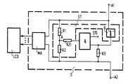
- a control circuit S which electrically drives each segment of the liquid crystal display unit LCDis connected to a liquid crystal display unit LCD.
- the control circuit Sgenerates two different voltage values for a multiplex control MA connected to the display electrodes of the liquid crystal display unit LCD for two predefinable positions of the device.
- the control circuit Shas a switchable voltage divider circuit ST for generating the two voltage values.
- the switchable voltage divider circuit STcontains a voltage divider connected to the two connection terminals A1, A2 of a supply voltage with the resistors R1, R2, a resistor R21 connected to the tap A of the voltage divider and a fork switch contact g connected to its second connection.
- a dark fieldis used for the aforementioned application display, ie a display in which the information is provided with light characters on a dark background, is preferred.
- the control circuit S described aboveis supplemented with an AND gate U.
- the output of the AND gate Uis connected to the second terminal of the resistor R21.
- the first input of the AND gate Uis connected via the fork switch contact g to the connection terminal A1 and the second input of the AND gate U is supplied with a control signal STS of a control device arranged in the communications technology device.
- the control signal STScan now be used to prevent the contrast from being switched when the position of the handset changes.
Landscapes
- Engineering & Computer Science (AREA)
- Chemical & Material Sciences (AREA)
- Crystallography & Structural Chemistry (AREA)
- Physics & Mathematics (AREA)
- Computer Hardware Design (AREA)
- General Physics & Mathematics (AREA)
- Theoretical Computer Science (AREA)
- Liquid Crystal Display Device Control (AREA)
- Liquid Crystal (AREA)
- Mobile Radio Communication Systems (AREA)
Abstract
Translated fromGermanDescription
Translated fromGermanDie Erfindung betrifft eine Steuerschaltung für eine insbesondere in ein Gerät der Nachrichtentechnik eingebaute Flüssigkristall-Anzeigeeinheit gemäß dem Oberbegriff des Patentanspruch 1.The invention relates to a control circuit for a liquid crystal display unit, which is installed in particular in a telecommunications device, according to the preamble of patent claim 1.
Flüssigkristall-Anzeigeeinheiten wurden bisher bevorzugt in Quarzuhren und Taschenrechnern eingesetzt. Da Flüssigkristall-Anzeigeeinheiten einen nahezu leistungslosen Betrieb gestatten und deshalb nur eine geringe Speiseleistung benötigen, werden diese im zunehmenden Maße auch in Geräten der Nachrichtentechnik eingesetzt.Liquid crystal display units have so far been used with preference in quartz watches and pocket calculators. Since liquid crystal display units allow almost powerless operation and therefore only require a low power supply, they are increasingly being used in telecommunications equipment.
In Flüssigkristall-Anzeigeeinheiten befinden sich zwischen einer front- und rückseitigen Polarisationsschicht sogenannte "verdrillte nematische Flüssigkristalle". Die Moleküle der mesogenen Verbindungen sind langgestreckt und die Längsachsen der Moleküle stehen in der nematischen Phase, wenn man von Wärmeschwankungen absieht, parallel. Unter Einfluß eines an den Flüssigkristall angelegten elektrischen Feldes finden sogenannte Frédericksz-Übergänge statt, so daß bei einer geeigneten Anordnung mit Polarisatoren die anfangs undurchsichtige Flüssigkeit durchsichtig wird.So-called "twisted nematic liquid crystals" are located in liquid crystal display units between a front and rear polarization layer. The molecules of the mesogenic compounds are elongated and the longitudinal axes of the molecules are parallel in the nematic phase, apart from thermal fluctuations. So-called Frédericksz transitions take place under the influence of an electric field applied to the liquid crystal, so that the initially opaque liquid becomes transparent with a suitable arrangement with polarizers.
Liegt kein äußeres elektrisches Feld an, dann ist die Richtung der Achsen jeder Molekülschicht gegenüber der benachbarten Molekülschicht um einen kleinen Winkel verdrillt. Trifft auf die verdrillt-planare Flüssigkristallschicht Licht, welches an der Eintrittsseite linear polarisiert in Richtung der mittleren Richtung der Längsachsen der Moleküle ist, so dreht sich in der Schicht die Polarisationsebene mit der schraubenartigen Struktur der Molekülschichten mit. Ist die Polarisationsrichtung des rückseitigen Polarisators die gleiche wie die mittlere Richtung der Längsachsen der Moleküle, so kann entsprechend polarisiertes Licht in die Flüssigkristall-Anzeigeeinheit eintreten und wird entsprechend der Verdrillung der verdrilltplanaren Schichten gedreht. Tritt beispielsweise das Licht (Beleuchtung durch Tageslicht oder Lampe) rückseitig mit horizontaler Polarisation ein, so ist dieses beim Austreten aus der Flüssigkristallschicht vertikal polarisiert. Ist der frontseitige Polarisator ebenfalls vertikal orientiert, so gelangt das Licht ungehindert durch diesen hindurch und die Bildfläche erscheint dem Betrachter hell.If there is no external electric field, the direction of the axes of each molecular layer is twisted by a small angle with respect to the neighboring molecular layer. Strikes the twisted-planar liquid crystal layer light, which polarizes linearly on the entrance side in the direction of the middle direction is the longitudinal axes of the molecules, the polarization plane with the screw-like structure of the molecular layers rotates in the layer. If the polarization direction of the rear polarizer is the same as the central direction of the longitudinal axes of the molecules, then appropriately polarized light can enter the liquid crystal display unit and is rotated in accordance with the twisting of the twisted planar layers. If, for example, the light (illumination by daylight or lamp) enters with horizontal polarization on the back, this is vertically polarized when exiting the liquid crystal layer. If the polarizer on the front is also oriented vertically, the light passes through it unhindered and the image surface appears bright to the viewer.
In Flüssigkristall-Anzeigeeinheiten ist die Flüssigkristallschicht zwischen rück- und frontseitigen Platten (und zwischen einer zwischen den Glasplatten umlaufenden Dichtung) eingebettet, welche mit durchsichtigen Elektroden versehen sind. Beim Anlegen einer Spannung an die beiden Elektroden wird die Flüssigkristallschicht einem elektrischen Feld ausgesetzt, welches eine Ausrichtung aller Molekülschichten in Feldrichtung bewirkt, wodurch die Verdrillung in der Flüssigkristallschicht und somit die Drehung der Polarisationsrichtung des durchtretenden Lichts entfällt. Tritt rückseitig Licht mit horizontaler Polarisation ein, so trifft dieses ebenfalls horizontal polarisiert am frontseitig vertikal orientierten Polarisator auf und wird von diesem nicht durchgelassen. Dem Betrachter erscheint damit die Bildfläche dunkel.In liquid crystal display units, the liquid crystal layer is embedded between rear and front plates (and between a seal running between the glass plates), which are provided with transparent electrodes. When a voltage is applied to the two electrodes, the liquid crystal layer is exposed to an electric field, which causes all molecular layers to be aligned in the field direction, as a result of which the twisting in the liquid crystal layer and thus the rotation of the polarization direction of the light passing through are eliminated. If light with horizontal polarization occurs on the rear, this also strikes horizontally polarized light on the front of the vertically oriented polarizer and is not let through by it. The viewer appears dark to the viewer.
Zur Darstellung von Zeichen, Grafiken und Bildern wird häufig eine Matrixanzeige, d.h. eine Anzeige mit horizontal und vertikal jeweils zueinander parallel angeordneten Bildelementen, verwendet. Zur Darstellung eines Satzes von bestimmten Zeichen, z.B. Zahlen, wird dagegen häufig die Segment-Anzeige, z.B. 7-Segment-Anzeige, verwendet. Für die Adressierung bzw. Selektion der Bildelemente und zu deren Helligkeitssteuerung ist mit der Flüssigkristall-Anzeigeeinheit eine Steuerschaltung verbunden. Zur Helligkeitssteuerung der Bildelemente wird häufig eine Pulsamplituden-Modulation verwendet, d.h. die Amplitude der Ansteuerimpulse bestimmt die Lichtdurchlässigkeit und damit die Helligkeit des Bildelements. Bei einer Multiplex-Ansteuerung mit hohem Multiplexverhältnis (z.B. 1:8) werden die Zeilen- und Spaltenelektroden mit kurzen Impulsen angesteuert, wobei die Differenz der Spannungsamplitude zwischen Spannung der ein- und ausgeschalteten Segmente (oder Bildpunkte) mit zunehmenden Multiplexverhältnis sinkt, so daß sich ein geringes Kontrastverhältnis der Flüssigkristall-Anzeigeeinheit ergibt.A matrix display is often used to display characters, graphics and images, i.e. a display with horizontally and vertically mutually parallel picture elements used. To represent a set of certain characters, e.g. Numbers, the segment display, e.g. 7-segment display, used. A control circuit is connected to the liquid crystal display unit for addressing or selecting the picture elements and for controlling their brightness. Pulse amplitude modulation is often used to control the brightness of the picture elements, i.e. the amplitude of the drive pulses determines the light transmission and thus the brightness of the picture element. In a multiplex control with a high multiplex ratio (e.g. 1: 8), the row and column electrodes are driven with short pulses, the difference in voltage amplitude between the voltage of the switched on and off segments (or pixels) decreasing with increasing multiplex ratio, so that results in a low contrast ratio of the liquid crystal display unit.
Wie die Isokontrastkennlinienfelder von Flüssigkristall-Anzeigeeinheiten aufzeigen, ist die Erkennbarkeit der Information von dem Beobachtungswinkelbereich abhängig. Eine Isokontrastkennlinie ist eine Linie in einem Polardiagramm, welche die Richtung im Raum angibt und anwelcher der Kontrast der Flüssigkristall-Anzeigeeinheit einen konstanten Wert hat. Je nach Lage der Flüssigkristall-Anzeigeeinheit (ausgedrückt durch die Winkel alpha und phi) ändert sich das Kontrastverhältnis.As the isocontrast characteristics of liquid crystal display units show, the recognizability of the information depends on the observation angle range. An isocontrast characteristic curve is a line in a polar diagram which indicates the direction in space and to which the contrast of the liquid crystal display unit has a constant value. The contrast ratio changes depending on the position of the liquid crystal display unit (expressed by the angles alpha and phi).
Aus der DE-PS 30 29 122 ist eine Flüssigkristall-Anzeigevorrichtung für ein Kraftfahrzeug bekannt. Die transmissive Anzeigeeinheit weist auf der Rückseite einen lichtführenden Körper auf, welcher zur wahlweisen Einleitung des Umgebungslichts oder des Lichts einer Lichtquelle in die Flüssigkristallschicht bewegbar ausgebildet ist. In der Tagstellung ist die Lichtquelle ausgeschaltet und das Tageslicht wird mittels einer Linse gebündelt und beleuchtet den lichtführenden Körper. Der lichtführende Körper weist rückseitig eine reflektierende Beschichtung auf, wodurch das einfallende Tageslicht die Flüssigkristallschicht von der Rückseite her beleuchtet. In der Nachtstellung liegt der lichtführende Körper auf der Rückseite der Flüssigkristall-Anzeigeeinheit an und die Lichtquelle ist eingeschaltet. Das von der reflektierenden Beschichtung des lichtführenden Körpers reflektierte Licht dient zur Beleuchtung der Flüssigkristall-Anzeigeeinheit. Die Helligkeit der aus der DE-PS 30 29 122 bekannten Flüssigkristall-Anzeigevorrichtung wird durch die Helligkeit des Umgebungslichtes oder der Lichtleistung der Lichtquelle gesteuert. Diese Werte werden so gewählt, daß innerhalb eines vorgegebenen Beobachtungswinkelbereichs die Information gut erkennbar ist.From DE-PS 30 29 122 a liquid crystal display device for a motor vehicle is known. The transmissive display unit has a light-guiding body on the back, which can be used for optional introduction the ambient light or the light of a light source is designed to be movable into the liquid crystal layer. In the day position, the light source is switched off and the daylight is bundled by means of a lens and illuminates the light-guiding body. The light-guiding body has a reflective coating on the back, as a result of which the incident daylight illuminates the liquid crystal layer from the back. In the night position, the light-guiding body rests on the back of the liquid crystal display unit and the light source is switched on. The light reflected by the reflective coating of the light-guiding body is used to illuminate the liquid crystal display unit. The brightness of the liquid crystal display device known from DE-PS 30 29 122 is controlled by the brightness of the ambient light or the light output of the light source. These values are chosen so that the information is clearly recognizable within a given observation angle range.
Der Erfindung liegt die Aufgabe zugrunde, eine Steuerschaltung für eine Flüssigkristall-Anzeigeeinheit derart auszugestalten, daß auch bei einer Veränderung der Lage der in ein Gerät eingebauten Flüssigkristall-Anzeigeeinheit die Erkennbarkeit der dargestellten Information weiterhin gewährleistet wird.The invention is based on the object of designing a control circuit for a liquid crystal display unit in such a way that, even when the position of the liquid crystal display unit installed in a device is changed, the recognizability of the information displayed is still ensured.
Diese Aufgabe wird erfindungsgemäß durch eine Steuerschaltung mit den Merkmalen des Patentanspruchs 1 gelöst.This object is achieved according to the invention by a control circuit having the features of patent claim 1.
Dadurch, daß die erfindungsgemäße Steuerschaltung bei einer Veränderung der Lage des Geräts automatisch auch den Kontrast verändert wird sichergestellt, daß auch für den neuen Beobachtungswinkelbereich die Erkennbarkeit der Information gewährleistet ist. Unter dem Kontrast ist der Quotient aus Differenz und Summe der Leuchtdichten von hellen und dunklen Teil (An-, Aussegmente) der Anzeigefläche zu verstehen.The fact that the control circuit according to the invention automatically changes the contrast when the position of the device changes also ensures that the recognizability of the information is also ensured for the new observation angle range. Below the contrast is the quotient of the difference and the sum of the luminance of to understand the light and dark part (on and off segments) of the display area.
Werden gemäß Patentanspruch 2 für eine mit den Anzeigeelektroden der Flüssigkristall-Anzeigeeinheit verbundene Mulitplex-Ansteuerung - entsprechend zwei vorgebbaren Lagen des Geräts - nur zwei verschiedene Spannungswerte erzeugt,so ist der Schaltungsaufwand für die Steuerschaltung gering. Solche zwei verschiedene Lagen treten bei dem Einbau der Flüssigkristall-Anzeigeeinheit in den Bedienhörern eines mobilen Funkfernsprechgeräts auf. In der nicht vorveröffentlichten P 35 07 016.1 ist eine zweiteilige Hörerauflage für den Bedienhörer vorgeschlagen, welche an geeigneter Stelle am Armaturenbrett befestigt ist. Der Bedienhörer weist auf seiner Oberseite in speziellen Feldern Anzeigeeinrichtungen und eine Wähltastatur auf. Bei abgenommenen Bedienhörer ist die Isokontrastkennlinie durch die Raumwinkel alpha = 10° und phi = 270° und bei aufgelegten Bedienhörer durch alpha = 45° und phi = 225° gekennzeichnet. Die Veränderung des Kontrastes durch Vorgabe zweier verschiedener Spannungswerte ist einfach durchzuführen.If, according to claim 2, only two different voltage values are generated for a multiplex control connected to the display electrodes of the liquid crystal display unit - corresponding to two predefinable positions of the device - the circuitry for the control circuit is low. Such two different positions occur when the liquid crystal display unit is installed in the handset of a mobile radio telephone set. In the unpublished P 35 07 016.1, a two-part handset support for the handset is proposed, which is attached to the dashboard at a suitable location. The top of the handset has display devices and a dialing keypad in special fields. When the handset is removed, the isocontrast characteristic is characterized by the solid angles alpha = 10 ° and phi = 270 ° and with the handset on-hook it is characterized by alpha = 45 ° and phi = 225 °. Changing the contrast by specifying two different voltage values is easy to carry out.
Vorzugsweise werden die beiden Spannungswerte mittels einer umschaltbaren Spannungsteilerschaltung erzeugt. Der Schaltungaufwand für die Umschaltung der Spannungsteilerschaltung ist besonders gering, wenn gemäß Patentanspruch 4 hierzu der Gabelumschaltkontakt oder gemäß Patentanspruch 5 ein Lagesensor verwendet wird.The two voltage values are preferably generated by means of a switchable voltage divider circuit. The switching outlay for switching over the voltage divider circuit is particularly low if, according to claim 4, the fork switch contact or, according to claim 5, a position sensor is used.
Wird gemäß Patentanspruch 6 die Umschaltung zusätzlich von einem Steuersignal einer im Gerät der Nachrichtentechnik angeordneten Steuereinrichtung abhängig gemacht, so kann auch für Montageorte, bei denen eine Veränderung des Kontrastes nicht erwünscht ist dem Wunsch des Kunden entsprochen werden.If the switchover is additionally made dependent on a control signal from a control device arranged in the communications technology device, the customer's request can also be met for assembly locations where a change in the contrast is not desired.
Weitere vorteilhafte Ausgestaltungen der Erfindung sind in den Unteransprüchen angegeben.Further advantageous embodiments of the invention are specified in the subclaims.
Die Erfindung wird im folgenden anhand einer in der Zeichnung dargestellten Ausführungsform näher beschrieben und erläutert.The invention is described and explained in more detail below with reference to an embodiment shown in the drawing.
Statische, ungemultiplexte Flüssigkristall-Anzeigeeinheiten werden beispielsweise mit einem Pegel von ± 5 V Wechselspannung (ca. 100 Hz) bei angesteuerten Segmenten betrieben, wobei der Pegel der "Aus"-Segmente gleich 0 V ist.Static, unmultiplexed liquid crystal display units are operated, for example, with a level of ± 5 V AC voltage (approx. 100 Hz) with activated segments, the level of the "off" segments being 0 V.
Bei gemultiplexten Flüssigkristall-Anzeigeeinheiten ist eine Ansteuerung mit einer Wechselspannung zwischen der jeweiligen Elektrode und der Gegenelektrode nur möglich, wenn der Pegel "Aus" > 0 V ist und der Pegel "An" < Max. Spannung ist. Die Differenz zwischen "Aus"- und "An"-Pegeln sinkt mit steigendem Multiplexverhältnis; damit sinkt auch das Kontrastverhältnis zwischen "Aus"- und "An"-Segmenten.In the case of multiplexed liquid crystal display units, control with an alternating voltage between the respective electrode and the counter electrode is only possible if the level "off"> 0 V and the level "on" <max. Voltage. The difference between "off" and "on" levels decreases with increasing multiplex ratio; this also reduces the contrast ratio between "off" and "on" segments.
Die Ansteuerspannungen der gemultiplexten Flüssigkristall-Anzeigeeinheit müssen nun so eingestellt werden, daß die "Aus"-Segmente bzw. Punkte unter den gewählten Beobachtungswinkel kaum sichtbar sind.The drive voltages of the multiplexed liquid crystal display unit must now be set so that the "off" segments or points are barely visible under the chosen observation angle.
Das Verhältnis der Ansteuerpegel
In Valvo: Flüssigkristallanzeigen Spezifikationen, 6.83, S. 58 ff ist eine Flüssigkristall-Anzeigeeinheit mit einem Multiplexverhältnis 1:8 beschrieben. Für alpha = 10° ist das Kontrastverhältnis mit 1,447, VOP typ mit 3,85 V, Von mit 1,66 V und Voff mit 1,12 V angegeben. Mit einer Flüssigkristall-Anzeigeeinheit LCD ist eine Steuerschaltung S verbunden, welches jedes Segment der Flüssigkristall-Anzeigeeinheit LCD elektrisch ansteuert. Die Steuerschaltung S erzeugt für zwei vorgebbare Lagen des Geräts zwei verschiedene Spannungswerte für eine mit den Anzeigeelektroden der Flüssigkristall-Anzeigeeinheit LCD verbundene Multiplex-Ansteuerung MA. Für die Erzeugung der beiden Spannungswerte weist die Steuerschaltung S eine umschaltbare Spannungsteilerschaltung ST auf.A liquid crystal display unit with a multiplex ratio of 1: 8 is described in Valvo: Liquid crystal display specifications, 6.83, p. 58 ff. For alpha = 10 ° the contrast ratio is given as 1.477, VOP type with 3.85 V, Von with 1.66 V and Voff with 1.12 V. A control circuit S which electrically drives each segment of the liquid crystal display unit LCD is connected to a liquid crystal display unit LCD. The control circuit S generates two different voltage values for a multiplex control MA connected to the display electrodes of the liquid crystal display unit LCD for two predefinable positions of the device. The control circuit S has a switchable voltage divider circuit ST for generating the two voltage values.
Die umschaltbare Spannungsteilerschaltung ST enthält einen mit den beiden Anschlußklemmen A1, A2 einer Versorgungsspannung verbundenen Spannungsteiler mit den Widerständen R1, R2, einen mit dem Abgriff A des Spannungsteilers verbundenen Widerstand R21 und einen mit dessen zweiten Anschluß in Verbindung stehenden Gabelumschaltkontakt g.The switchable voltage divider circuit ST contains a voltage divider connected to the two connection terminals A1, A2 of a supply voltage with the resistors R1, R2, a resistor R21 connected to the tap A of the voltage divider and a fork switch contact g connected to its second connection.
In Abhängigkeit von der Schaltstellung des Gabelumschaltkontaktes g, d.h. in Abhängigkeit ob der Bedienhörer abgehoben ist oder nicht, wird für die Multiplexansteuerung MA der eine oder andere Spannungswert vorgegeben. Ist beispielsweise der Bedienhörer in die am Armaturenbrett angeordneten Hörerauflage eingebracht, so ist der Spannungswert für die Multiplex-Ansteuerung MA höher. Bei einer Erhöhung der Spannung VOP auf beispielsweise 5 V ergibt sich für die angegebene Flüssigkristall-Anzeigeeinheit Von zu 2,15 V und Voff zu 1,45 V. Durch den höheren Spannungswert erhöht sich auch der Kontrast sowohl der "An"- als auch der "Aus"-Segmente, so daß nun für diesen Beobachtungswinkelbereich die Information gut erkennbar ist. Bei alpha = 10° dagegen werden die "Aus"-Segmente bereits sichtbar, d.h. für diesen Beobachtungswinkel ist der Kontrast der "Aus"-Segmente zu hoch.Depending on the switching position of the fork switch contact g, ie depending on whether the handset is off-hook or not, one or the other voltage value is specified for the multiplex control MA. If, for example, the handset is inserted into the handset rest arranged on the dashboard, the voltage value for the multiplex control MA is higher. If the voltage VOP is increased to, for example, 5 V, the indicated liquid crystal display unit has Von of 2.15 V and Voff of 1.45 V. The higher voltage value also increases the contrast of both the "on" as well as the "off" segments, so that the information is now clearly recognizable for this observation angle range. With alpha = 10 °, on the other hand, the "off" segments are already visible, ie the contrast of the "off" segments is too high for this observation angle.
Für den vorgenannten Anwendungsfall wird eine Dunkelfeld anzeige, d.h. eine Anzeige, bei der die Information mit hellen Zeichen auf einem dunklen Untergrund erfolgt, bevorzugt.A dark field is used for the aforementioned application display, ie a display in which the information is provided with light characters on a dark background, is preferred.
Ist die Hörerauflage beispielsweise im Bereich zwischen den Vordersitzen des Kraftfahrzeugs befestigt, so wird die vorstehend geschilderte Steuerschaltung S mit einem UND-Glied U ergänzt. Der Ausgang des UND-Glied U ist mit dem zweiten Anschluß des Widerstands R21 verbunden. Der erste Eingang des UND-Glieds U steht über dem Gabelumschaltkontakt g mit der Anschlußklemme A1 in Verbindung und dem zweiten Eingang des UND-Glieds U wird ein Steuersignal STS einer im Gerät der Nachrichtentechnik angeordneten Steuereinrichtung zugeführt. Mittels dem Steuersignal STS kann nun verhindert werden, daß bei einer Veränderung der Lage des Bedienhörers eine Umschaltung des Kontrastes vorgenommen wird.If the handset rest is fastened, for example, in the area between the front seats of the motor vehicle, the control circuit S described above is supplemented with an AND gate U. The output of the AND gate U is connected to the second terminal of the resistor R21. The first input of the AND gate U is connected via the fork switch contact g to the connection terminal A1 and the second input of the AND gate U is supplied with a control signal STS of a control device arranged in the communications technology device. The control signal STS can now be used to prevent the contrast from being switched when the position of the handset changes.
Claims (8)
Translated fromGermanApplications Claiming Priority (2)
| Application Number | Priority Date | Filing Date | Title |
|---|---|---|---|
| DE19853534703DE3534703A1 (en) | 1985-09-28 | 1985-09-28 | CONTROL CIRCUIT FOR A LIQUID CRYSTAL DISPLAY UNIT |
| DE3534703 | 1985-09-28 |
Publications (2)
| Publication Number | Publication Date |
|---|---|
| EP0221582A2true EP0221582A2 (en) | 1987-05-13 |
| EP0221582A3 EP0221582A3 (en) | 1988-09-28 |
Family
ID=6282247
Family Applications (1)
| Application Number | Title | Priority Date | Filing Date |
|---|---|---|---|
| EP86201631AWithdrawnEP0221582A3 (en) | 1985-09-28 | 1986-09-23 | Control circuit for a liquid-crystal display unit |
Country Status (5)
| Country | Link |
|---|---|
| US (1) | US4832454A (en) |
| EP (1) | EP0221582A3 (en) |
| JP (1) | JPS6281628A (en) |
| DE (1) | DE3534703A1 (en) |
| DK (1) | DK458086A (en) |
Cited By (3)
| Publication number | Priority date | Publication date | Assignee | Title |
|---|---|---|---|---|
| EP0272018A3 (en)* | 1986-12-04 | 1990-04-11 | Sony Corporation | Liquid crystal display apparatus |
| EP0329399A3 (en)* | 1988-02-16 | 1991-05-22 | Nec Corporation | Small-sized equipment with a liquid crystal display |
| WO1995027973A1 (en)* | 1994-04-07 | 1995-10-19 | The Boeing Company | Image display system allowing multiple users to view a single display or a single user to view multiple displays |
Families Citing this family (5)
| Publication number | Priority date | Publication date | Assignee | Title |
|---|---|---|---|---|
| US5835074A (en)* | 1992-12-30 | 1998-11-10 | Advanced Displays Corporation | Method to change the viewing angle in a fixed liquid crystal display by changing the pre-tilt angle in the liquid crystal layer with a bias voltage |
| US6646626B1 (en)* | 1999-11-01 | 2003-11-11 | Motorola, Inc. | Method and apparatus for automatic viewing angle adjustment for liquid crystal display |
| KR100729762B1 (en)* | 2000-11-14 | 2007-06-20 | 삼성전자주식회사 | Liquid crystal display with improved side contrast ratio and side color reproducibility |
| US7116287B2 (en)* | 2001-05-09 | 2006-10-03 | Eastman Kodak Company | Drive for cholesteric liquid crystal displays |
| US10068512B2 (en)* | 2015-07-07 | 2018-09-04 | Texas Instruments Incorporated | Modulator for a MUX LCD |
Family Cites Families (11)
| Publication number | Priority date | Publication date | Assignee | Title |
|---|---|---|---|---|
| JPS51132940A (en)* | 1975-05-14 | 1976-11-18 | Sharp Corp | Electric source apparatus |
| JPS5255832A (en)* | 1975-11-04 | 1977-05-07 | Seiko Epson Corp | Passive display-type electronic apparatus |
| JPS5917430B2 (en)* | 1977-10-31 | 1984-04-21 | シャープ株式会社 | Matrix type liquid crystal display device |
| JPS54126497A (en)* | 1978-03-24 | 1979-10-01 | Sharp Corp | Dap-type liquid crystal display device |
| US4236150A (en)* | 1978-10-18 | 1980-11-25 | Minnesota Mining And Manufacturing Company | Liquid crystal display system |
| JPS5622468A (en)* | 1979-08-01 | 1981-03-03 | Nissan Motor | Liquid crystal display unit |
| US4462027A (en)* | 1980-02-15 | 1984-07-24 | Texas Instruments Incorporated | System and method for improving the multiplexing capability of a liquid crystal display and providing temperature compensation therefor |
| DE3024530C2 (en)* | 1980-06-28 | 1982-06-16 | Eurosil GmbH, 8000 München | Liquid crystal control voltage circuit |
| CH632368B (en)* | 1980-12-19 | Asulab Sa | LIQUID CRYSTAL DISPLAY CELL. | |
| JPH0654960B2 (en)* | 1983-10-20 | 1994-07-20 | シチズン時計株式会社 | Driving method for liquid crystal display device |
| DE3445438A1 (en)* | 1984-12-13 | 1986-06-19 | Blaupunkt-Werke Gmbh, 3200 Hildesheim | METHOD AND ARRANGEMENT FOR CONTROLLING LIQUID CRYSTAL DISPLAY DEVICES |
- 1985
- 1985-09-28DEDE19853534703patent/DE3534703A1/ennot_activeWithdrawn
- 1986
- 1986-09-22USUS06/909,810patent/US4832454A/ennot_activeExpired - Fee Related
- 1986-09-23EPEP86201631Apatent/EP0221582A3/ennot_activeWithdrawn
- 1986-09-25DKDK458086Apatent/DK458086A/ennot_activeApplication Discontinuation
- 1986-09-25JPJP61225066Apatent/JPS6281628A/enactivePending
Cited By (3)
| Publication number | Priority date | Publication date | Assignee | Title |
|---|---|---|---|---|
| EP0272018A3 (en)* | 1986-12-04 | 1990-04-11 | Sony Corporation | Liquid crystal display apparatus |
| EP0329399A3 (en)* | 1988-02-16 | 1991-05-22 | Nec Corporation | Small-sized equipment with a liquid crystal display |
| WO1995027973A1 (en)* | 1994-04-07 | 1995-10-19 | The Boeing Company | Image display system allowing multiple users to view a single display or a single user to view multiple displays |
Also Published As
| Publication number | Publication date |
|---|---|
| EP0221582A3 (en) | 1988-09-28 |
| US4832454A (en) | 1989-05-23 |
| DE3534703A1 (en) | 1987-04-09 |
| JPS6281628A (en) | 1987-04-15 |
| DK458086D0 (en) | 1986-09-25 |
| DK458086A (en) | 1987-03-29 |
Similar Documents
| Publication | Publication Date | Title |
|---|---|---|
| EP0263537B1 (en) | Method and circuit arrangement for controlling the brightness and the depending temperature of a lamp, espcially for the lighting of an lcd display | |
| DE69804156T2 (en) | Dual display arrangement and terminal | |
| DE4000451B4 (en) | Electro-optical liquid crystal switching element | |
| DE69933386T2 (en) | REFLECTIVE / TRANSMITTING DUAL MODE LIQUID CRISIS DISPLAY | |
| EP2463152B1 (en) | Lighting element in external mirror | |
| DE4003843A1 (en) | FERROELECTRIC LIQUID CRYSTAL DISPLAY | |
| EP1084892B1 (en) | Display device | |
| DE2634313A1 (en) | LIQUID CRYSTAL DISPLAY DEVICE | |
| KR920015152A (en) | Electro-optical device | |
| DE2722388A1 (en) | PASSIVE ELECTRO-OPTICAL INDICATOR | |
| EP0221582A2 (en) | Control circuit for a liquid-crystal display unit | |
| DE102004022903A1 (en) | Two screen/single panel liquid crystal display having central liquid crystal layer and first/second substrate with outer voltage applicator plates changing liquid crystal format and outer lighting panels | |
| DE10062723A1 (en) | Head-Up Display | |
| DE3340468A1 (en) | Liquid crystal display | |
| DE19737726C1 (en) | Display instrument for automobile dashboard | |
| DE19708066B4 (en) | liquid-crystal display | |
| DE3738414A1 (en) | Device for illuminating passive information displays, preferably LCDs | |
| DE102008033911A1 (en) | Motor vehicle display or motor vehicle lighting unit has light sources, reversibly producible darkening medium, cover, and display unit | |
| DE3314632A1 (en) | ARRANGEMENT FOR REDUCING THE REMAINING TRANSMISSION OF LCD DISPLAYS | |
| DE2542235B2 (en) | LIQUID CRYSTAL DISPLAY WITH BISTABLE CHOLESTERINIC LIQUID CRYSTAL LAYER | |
| DE10252166A1 (en) | Matrix display with pixel selection arrangement of neighboring pixels being connected mutually with bordering control lines | |
| DE10218301A1 (en) | display device | |
| DE3438756A1 (en) | Double twisted cell display device | |
| DE3300273A1 (en) | Display device | |
| DE3504886A1 (en) | Liquid-crystal display device and method for driving it |
Legal Events
| Date | Code | Title | Description |
|---|---|---|---|
| PUAI | Public reference made under article 153(3) epc to a published international application that has entered the european phase | Free format text:ORIGINAL CODE: 0009012 | |
| AK | Designated contracting states | Kind code of ref document:A2 Designated state(s):DE FR GB SE | |
| RAP1 | Party data changed (applicant data changed or rights of an application transferred) | Owner name:N.V. PHILIPS' GLOEILAMPENFABRIEKEN Owner name:PHILIPS PATENTVERWALTUNG GMBH | |
| PUAL | Search report despatched | Free format text:ORIGINAL CODE: 0009013 | |
| AK | Designated contracting states | Kind code of ref document:A3 Designated state(s):DE FR GB SE | |
| 17P | Request for examination filed | Effective date:19890320 | |
| 17Q | First examination report despatched | Effective date:19901128 | |
| STAA | Information on the status of an ep patent application or granted ep patent | Free format text:STATUS: THE APPLICATION IS DEEMED TO BE WITHDRAWN | |
| 18D | Application deemed to be withdrawn | Effective date:19931224 | |
| APAF | Appeal reference modified | Free format text:ORIGINAL CODE: EPIDOSCREFNE | |
| RIN1 | Information on inventor provided before grant (corrected) | Inventor name:WALTERS, ECKHARD, DIPL.-ING. |