EP0215249B1 - A transfusion apparatus - Google Patents
A transfusion apparatusDownload PDFInfo
- Publication number
- EP0215249B1 EP0215249B1EP86110513AEP86110513AEP0215249B1EP 0215249 B1EP0215249 B1EP 0215249B1EP 86110513 AEP86110513 AEP 86110513AEP 86110513 AEP86110513 AEP 86110513AEP 0215249 B1EP0215249 B1EP 0215249B1
- Authority
- EP
- European Patent Office
- Prior art keywords
- pump
- section
- peristaltic
- detecting
- delivery
- Prior art date
- Legal status (The legal status is an assumption and is not a legal conclusion. Google has not performed a legal analysis and makes no representation as to the accuracy of the status listed.)
- Expired
Links
Images


Classifications
- A—HUMAN NECESSITIES
- A61—MEDICAL OR VETERINARY SCIENCE; HYGIENE
- A61M—DEVICES FOR INTRODUCING MEDIA INTO, OR ONTO, THE BODY; DEVICES FOR TRANSDUCING BODY MEDIA OR FOR TAKING MEDIA FROM THE BODY; DEVICES FOR PRODUCING OR ENDING SLEEP OR STUPOR
- A61M1/00—Suction or pumping devices for medical purposes; Devices for carrying-off, for treatment of, or for carrying-over, body-liquids; Drainage systems
- A—HUMAN NECESSITIES
- A61—MEDICAL OR VETERINARY SCIENCE; HYGIENE
- A61M—DEVICES FOR INTRODUCING MEDIA INTO, OR ONTO, THE BODY; DEVICES FOR TRANSDUCING BODY MEDIA OR FOR TAKING MEDIA FROM THE BODY; DEVICES FOR PRODUCING OR ENDING SLEEP OR STUPOR
- A61M5/00—Devices for bringing media into the body in a subcutaneous, intra-vascular or intramuscular way; Accessories therefor, e.g. filling or cleaning devices, arm-rests
- A61M5/14—Infusion devices, e.g. infusing by gravity; Blood infusion; Accessories therefor
- A61M5/142—Pressure infusion, e.g. using pumps
- A61M5/14212—Pumping with an aspiration and an expulsion action
- A61M5/14228—Pumping with an aspiration and an expulsion action with linear peristaltic action, i.e. comprising at least three pressurising members or a helical member
- A—HUMAN NECESSITIES
- A61—MEDICAL OR VETERINARY SCIENCE; HYGIENE
- A61M—DEVICES FOR INTRODUCING MEDIA INTO, OR ONTO, THE BODY; DEVICES FOR TRANSDUCING BODY MEDIA OR FOR TAKING MEDIA FROM THE BODY; DEVICES FOR PRODUCING OR ENDING SLEEP OR STUPOR
- A61M5/00—Devices for bringing media into the body in a subcutaneous, intra-vascular or intramuscular way; Accessories therefor, e.g. filling or cleaning devices, arm-rests
- A61M5/14—Infusion devices, e.g. infusing by gravity; Blood infusion; Accessories therefor
- A61M5/168—Means for controlling media flow to the body or for metering media to the body, e.g. drip meters, counters ; Monitoring media flow to the body
- A61M5/16804—Flow controllers
Definitions
- This inventionrelates to a transfusion apparatus useful for an automatic dropper and the like.
- peristaltic finger pumpsas a transfusion apparatus useful for an automatic dropper (for example, the Japanese Laid- open Patent Application 58-165868).
- a flexible transfusion tubeis squeezed by movement of a plurality of finger elements in the liquid-feeding direction for supplying a constant amount of a liquid.
- the Japanese Utility Model Publication 5 727 463discloses a transfusion apparatus for preventing back flow, in which a time point of releasing a complete occlusion of the transfusion tube through rotation of a pressing element of the peristaltic pump is detected to provide a signal which allows a driving motor of the pump to rotate for a predetermined period of time at a higher velocity than its normal rotation, thereby to supplement a back flow portion in a short time.
- the driving motor of the finger pumpis rotated faster than the normal rotation from a time point of releasing the complete occlusion of the tube (point P), as shown in Fig. 5. It is true that a period of the back flow is reduced, but the delivery flow rate is still somewhat stagnated and the stagnation may not be neglected especially at the lower driving velocity of the pump, resulting in difficulty of its application in the automatically dropping transfusion apparatus.
- US Patent 4 469 481discloses an infusion apparatus being provided so as to vary the respective liquid flow as a function of the actual need.
- the apparatuscomprises a memory storing a basic pattern corresponding to the basis infusion amount and individual patterns such as meal patterns in the case of insulin infusion, which are read from the memory on a corresponding order by the patient and are superposed to the basic pattern.
- the motor for the pumpis provided with a detector, the signals of which are counted in order to terminate the motor rotation after a determined number of revolutions corresponding to the infusion amount being computed for the respective time.
- the automatic dropping transfusion apparatusrequires a flow rate characteristic of the pump having a stable flow rate and an accurate infusion over the wide flow range for its use of injecting a pharmaceutical liquid into a human body.
- the stable flow rate in the lower flow rangeis highly desired for infants and serious patients.
- the peristaltic finger pumpshows an approximately trapezoidal wave form of delivery and an approximately V-shaped wave form of the back flow upon release of the pressing and occluding action of the finger elements on the transfusion tube, so that the flow rate characteristic cannot be constant.
- the pump of such typerequires its drive control capable of approaching not only the increasing and decreasing ranges of the flow rate in the trapezoidal wave form but also the back flow wave form toward a predeterminded flow rate.
- the maximum delivery amount (DV M ) of the trapezoidal wave formis set to a referential amount and the instantaneous delivery amount (DVn) is determined at a given position (n).
- the peristaltic rate at this positionis then set to be multiplied by a factor of DV M /DVn in order to maintain the delivery amount at a constant value of DV M thereby to achieve the stable flow rate characteristic on the delivery side.
- the factor of DV M /DVnmay be determined by previous experiments.
- the transfusion apparatus of the inventioncomprises a pump section, a detecting section and a drive controlling section, said pump section being provided for sequentially pressing and occluding a transfusion tube by means of a plurality of finger elements of a peristaltic type, the peristaltic movement being determined by said finger elements thereby to feed a liquid, the velocity of the pump, for the purpose of the equalisation of the liquid flow rate, being controlled by said drive controlling section using a signal detected by said detecting section, in which transfusion apparatus the detecting section has a circuit for detecting a reference position in the cycle of periodic peristaltic movement to the pump to generate its corresponding detection signal and a circuit for detecting the actual working position in the cycle of periodic peristaltic movement of the pump deviated from the reference position thereby to generate its corresponding detection signal, said drive controlling section being provided for receiving both detected signals representing the actual difference between the working position and the reference position from the detecting section to compute and control a peristaltic rate thereby to maintain a constant delivery amount of
- a maximum delivery amount (DV M ) in an approximately trapezoidal wave form of delivery in the pump sectionis set to a referential amount
- the drive controlling sectionis set to compute and control the peristaltic rate (Vn) at a given position established for an instantaneous delivery amount (DVn) in accordance with the following equation: wherein K is a constant, n is 0, 1, 2, 3 -----, and Vn does not exceed a given maximum rate but is a given maximum rate for DVn s 0.
- the maximum rateis preferably maintained so as to offset a negative integrated amount of the delivery from a transition point of the instantaneous delivery amount (DVn) from negative to positive.
- the position of the periodical peristaltic movement of the pump sectionmay be properly detected to provide the signal, from which the peristaltic rate may be computed for stabilizing the delivery flow rate in the total delivery cycle especially for the automatic dropper requiring a micro-flow rate characteristic, thereby to achieve high precision of feeding an infusion liquid.
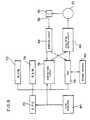
- Figure 1shows a system of one embodiment of the transfusion apparatus according to the invention, which comprises principally a pump section 10, a detecting section 12 and a drive controlling section 14.
- the pump section 10comprises an elastic transfusion tube 16 made of polyvinylchloride or silicone, a plurality of peristaltic finger elements 18 disposed on one side of the transfusion tube 16 for sequentially occluding and opening the latter, and a back plate 20 disposed oppositely to the finger elements 18 for securing the other side of the transfusion tube 16, as shown in Fig. 2.
- Each finger elementis supported by a holder 22 and provided with an elongated hole 24 for positioning therein an eccentric cam 26, through which is inserted a rotary shaft 28, thereby to generate the required peristaltic movement of the finger elements 18.
- each eccentric cam 26is arranged so as to be delayed at an angle of 360 ° /the number of cams relative to an adjacent upstream cam fixed to the same rotary shaft 28, so that a rotating movement of the eccentric cam may be converted to a linear movement of the finger elements 18 for urging and feeding a liquid in the transfusion tube 16.
- the rotary shaft 28 at its one endis connected through a transmission mechanism 30 to a driving shaft 34 of a pulse motor 32 while its other end is provided with a rotation-detecting disc 36 which includes a detector 38 for detecting a reference position of the peristaltic movement and another detector 40 for detecting a rotation angle or a working position of the peristaltic movement from the reference position (see Fig. 4).
- the transfusion tube 16 of the pump section 10thus constructed on its upstream side is connected through a dropping cylinder 42 to a bottle 44 of a pharmaceutical liquid while on its downstream is provided with an injection needle 46.
- the detecting section 12comprises a detector 38 for detecting the reference position, another detector 40 for detecting the working position and a detecting circuit 48 for the reference/working positions.
- the detector 38 for the reference positionis formed of a photo-electric detector which comprises a pair of light- emitting diodes for detecting an aperture 50 corresponding to the reference position on a single circumferential site of the rotation-detecting disc 36 and a photo-transistor, while the detector 40 for the working position comprises a similar photo-electric detector for detecting a plurality of apertures 52 equally spaced apart along a slightly inner circle relative to the aperture 50 on the disc 36.
- the detecting circuit 48may generate a predetermined working signal which is based on the detected signals of the reference/working positions by the respective photo-electric detectors.
- the detecting section 12has a function of transmitting a position of the peristaltic movement in the pump section 10 to the drive controlling section 14.
- the drive controlling section 14receives the signal from the detecting section 12 to grasp the position of the peristaltic movement in the pump section 10 and has data of an instantaneous delivery amount at that position, which has been previously determined by experiments, for computing and controlling a constant delivery amount.
- the drive controlling section 14comprises a flow rate setter 54, a first computer circuit 56, a second computer circuit 58 and a pulse motor driving circuit 60.
- the maximum delivery amount (DV M ) of the approximately trapezoidal wave formis set to the referential amount based on the flow rate characteristic of the transfusion tube derived from a given peristaltic movement in the pump section 10, while a ratio DV M /DVn has been previously determined by experiments from data of the instantaneous delivery amount DVn at a given position (n).
- a shift ratio Cn of the peristaltic movementmay be computed depending on the working signal received from the detector 48 for maintaining the delivery amount at a constant level according to the following equation;
- a velocity Vn of the peristaltic movementmay be computed dependidng on the shift ratio Cn for ensuring the constant delivery amount according to the following equation; wherein K is a constant, n is 0, 1, 2, 3 -----, and Vn does not exceed a given maximum rate but is a given maximum rate for DVn a 0.
- the optimal velocity of the peristaltic movement Vn thus obtainedis output as a signal for drive-controlling the pulse motor 32 through the pulse motor driving circuit 60.
- the control of the shift ratio Cn represented by the equation (1)provides a curve of an actual delivery characteristic, as shown in Fig. 6. Further, if the maximum rate is maintained so as to offset a negative integrated amount of the delivery from a transition point of the instantaneous delivery amount (DVn) from negative to positive, then the actual delivery characteristc may be ideally and highly stable, as shown in Fig. 7.
- the transfusion apparatusmay utilize a micro-computer as the computer circuit for the drive controlling section 14 in the above embodiment.
- Figure 8shows a system comprising the micro-computer as the computer circuit, wherein reference 70 represents a CPU which is connected to ROM 72, RAM 74, a counter/timer circuit 76 and a I/O port 78, as well as an optional clock oscillator 80, respectively.
- the counter/timer circuit 76 and the I/O port 78are connected to the detector 48 for the reference/working positions and the pulse motor driving circuit 60, while the VO port 78 is connected to an external operating device 82 capable of externally inputting and monitoring.
- the calculation and the control for driving the pulse motor 32may be readily achieved in the drive controlling section 14.
- FIG. 9One example of a flow chart for operating the above system is shown in Fig. 9.
- various setting values, equations for calculation and system-controlling programsare stored in the CPU 70, the ROM 72 and the RAM 74 for determining if the peristaltic movement of the pump section is located at the reference position in relation to the signal received from the detecting circuit 48 through the I/O port 78. If it is located on the reference position, then the position is set to 0 (zero point) and the calculation of the first computer circuit 56 (according to the equation (1)) is carried out, followed by the calculation of the second computer circuit 58 (according to the equation (2)), and the resultant values are fed throught the I/O port 78 to the pulse motor driving circuit 60. Thereafter, a given working position of the peristaltic movement in the pump section is grasped and the same procedure of the calculation is repeated each time for feeding the controlling signal to the pulse motor driving circuit 60 through the I/O port 78.
- the driving control of the pump sectionmay be readily, accurately and programmably realized depending on its purpose of application.
- the transfusion tubemay be pressed and occluded with its tip envelope being deformed by the plurality of the peristaltic finger elements, and that the rate of the peristaltic movement may be shifted so as to maintain the constant delivery flow rate and the minute variation of the delivery flow rate.
- the transfusion apparatus according to the inventioncompared with the conventional apparatus, has the stable delivery characteristic for the micro-transfusion at the low driving velocity of the pump section and thus very useful for the automatic dropper.
Landscapes
- Health & Medical Sciences (AREA)
- Heart & Thoracic Surgery (AREA)
- Hematology (AREA)
- Anesthesiology (AREA)
- Biomedical Technology (AREA)
- Engineering & Computer Science (AREA)
- Vascular Medicine (AREA)
- Life Sciences & Earth Sciences (AREA)
- Animal Behavior & Ethology (AREA)
- General Health & Medical Sciences (AREA)
- Public Health (AREA)
- Veterinary Medicine (AREA)
- Infusion, Injection, And Reservoir Apparatuses (AREA)
- Reciprocating Pumps (AREA)
- External Artificial Organs (AREA)
Description
- This invention relates to a transfusion apparatus useful for an automatic dropper and the like.
- There have hitherto been known peristaltic finger pumps as a transfusion apparatus useful for an automatic dropper (for example, the Japanese Laid- open Patent Application 58-165868). In such finger pumps, a flexible transfusion tube is squeezed by movement of a plurality of finger elements in the liquid-feeding direction for supplying a constant amount of a liquid.
- It has been found from determination of a flow rate on the delivery side of the pump that an approximately trapezoidal wave form of delivery and an approximately V-shaped wave form of back flow upon release of a pressing action by the finger element on the transfusion tube are repeated (see Figure 5). Thus, the conventional finger pumps can not maintain a constant flow rate on the delivery side and therefore may not be readily utilized for the automatic dropper.
- From this viewpoint, there have been various proposals for maintaining the constant flow rate on the delivery side in the peristaltic pumps for such applications. For example, the Japanese Utility Model Publication 5 727 463 discloses a transfusion apparatus for preventing back flow, in which a time point of releasing a complete occlusion of the transfusion tube through rotation of a pressing element of the peristaltic pump is detected to provide a signal which allows a driving motor of the pump to rotate for a predetermined period of time at a higher velocity than its normal rotation, thereby to supplement a back flow portion in a short time. However, if the proposed tranfusion apparatus is applied to a peristaltic finger pump, the driving motor of the finger pump is rotated faster than the normal rotation from a time point of releasing the complete occlusion of the tube (point P), as shown in Fig. 5. It is true that a period of the back flow is reduced, but the delivery flow rate is still somewhat stagnated and the stagnation may not be neglected especially at the lower driving velocity of the pump, resulting in difficulty of its application in the automatically dropping transfusion apparatus.
- US Patent 4 469 481 discloses an infusion apparatus being provided so as to vary the respective liquid flow as a function of the actual need. The apparatus comprises a memory storing a basic pattern corresponding to the basis infusion amount and individual patterns such as meal patterns in the case of insulin infusion, which are read from the memory on a corresponding order by the patient and are superposed to the basic pattern. The motor for the pump is provided with a detector, the signals of which are counted in order to terminate the motor rotation after a determined number of revolutions corresponding to the infusion amount being computed for the respective time.
- Usually, the automatic dropping transfusion apparatus requires a flow rate characteristic of the pump having a stable flow rate and an accurate infusion over the wide flow range for its use of injecting a pharmaceutical liquid into a human body. In particular, the stable flow rate in the lower flow range is highly desired for infants and serious patients. For example, the peristaltic finger pump shows an approximately trapezoidal wave form of delivery and an approximately V-shaped wave form of the back flow upon release of the pressing and occluding action of the finger elements on the transfusion tube, so that the flow rate characteristic cannot be constant. For this reason, the pump of such type requires its drive control capable of approaching not only the increasing and decreasing ranges of the flow rate in the trapezoidal wave form but also the back flow wave form toward a predeterminded flow rate.
- For a transfusion apparatus according to the preamble of
claim 1 these problems are solved by the characteristic features ofclaim 1. - In accordance with the invention, as shown in Fig. 5, for the flow rate characteristic of delivery from the transfusion tube accompanied with a certain peristaltic movement of the finger elements in the conventional peristaltic finger pump, the maximum delivery amount (DVM) of the trapezoidal wave form is set to a referential amount and the instantaneous delivery amount (DVn) is determined at a given position (n). The peristaltic rate at this position is then set to be multiplied by a factor of DVM/DVn in order to maintain the delivery amount at a constant value of DVM thereby to achieve the stable flow rate characteristic on the delivery side. The factor of DVM/DVn may be determined by previous experiments.
- Accordingly, the transfusion apparatus of the invention comprises a pump section, a detecting section and a drive controlling section, said pump section being provided for sequentially pressing and occluding a transfusion tube by means of a plurality of finger elements of a peristaltic type, the peristaltic movement being determined by said finger elements thereby to feed a liquid, the velocity of the pump, for the purpose of the equalisation of the liquid flow rate, being controlled by said drive controlling section using a signal detected by said detecting section, in which transfusion apparatus the detecting section has a circuit for detecting a reference position in the cycle of periodic peristaltic movement to the pump to generate its corresponding detection signal and a circuit for detecting the actual working position in the cycle of periodic peristaltic movement of the pump deviated from the reference position thereby to generate its corresponding detection signal, said drive controlling section being provided for receiving both detected signals representing the actual difference between the working position and the reference position from the detecting section to compute and control a peristaltic rate thereby to maintain a constant delivery amount of the pump section.
- In the transfusion apparatus according to the invention, it is preferred that a maximum delivery amount (DVM) in an approximately trapezoidal wave form of delivery in the pump section is set to a referential amount, and that the drive controlling section is set to compute and control the peristaltic rate (Vn) at a given position established for an instantaneous delivery amount (DVn) in accordance with the following equation:

- In this case, the maximum rate is preferably maintained so as to offset a negative integrated amount of the delivery from a transition point of the instantaneous delivery amount (DVn) from negative to positive.
- In accordance with the invention, the position of the periodical peristaltic movement of the pump section may be properly detected to provide the signal, from which the peristaltic rate may be computed for stabilizing the delivery flow rate in the total delivery cycle especially for the automatic dropper requiring a micro-flow rate characteristic, thereby to achieve high precision of feeding an infusion liquid.
- The invention will now be described in more detail for its preferred embodiments with reference to the accompanying drawings.
- Figure 1 shows a system of one embodiment of the transfusion appratus according to the invention;
- Figure 2 is a partial sectional side view of the pump section in Fig. 1;
- Figure 3 is a sectional view taken along the line III-III in Fig. 2;
- Figure 4 is a side view as seen from the side IV of Fig. 2;
- Figure 5 is a wave form diagram showing the delivery flow characteristic of the transfusion apparatus in Fig. 1 when the peristaltic rate is set constant;
- Figures 6 and 7 are wave form diagrams showing the delivery flow characteristic of the transfusion apparatus according to the invention;
- Figure 8 shows a system of the micro-computerized drive controlling section of the transfusion apparatus according to the invention; and
- Figure 9 is a flow chart for operating the system of Fig. 8.
- Figure 1 shows a system of one embodiment of the transfusion apparatus according to the invention, which comprises principally a
pump section 10, a detectingsection 12 and adrive controlling section 14. - At first, the
pump section 10 comprises anelastic transfusion tube 16 made of polyvinylchloride or silicone, a plurality ofperistaltic finger elements 18 disposed on one side of thetransfusion tube 16 for sequentially occluding and opening the latter, and aback plate 20 disposed oppositely to thefinger elements 18 for securing the other side of thetransfusion tube 16, as shown in Fig. 2. Each finger element is supported by aholder 22 and provided with anelongated hole 24 for positioning therein aneccentric cam 26, through which is inserted arotary shaft 28, thereby to generate the required peristaltic movement of thefinger elements 18. In this case, eacheccentric cam 26 is arranged so as to be delayed at an angle of 360° /the number of cams relative to an adjacent upstream cam fixed to the samerotary shaft 28, so that a rotating movement of the eccentric cam may be converted to a linear movement of thefinger elements 18 for urging and feeding a liquid in thetransfusion tube 16. Therotary shaft 28 at its one end is connected through atransmission mechanism 30 to adriving shaft 34 of apulse motor 32 while its other end is provided with a rotation-detectingdisc 36 which includes adetector 38 for detecting a reference position of the peristaltic movement and anotherdetector 40 for detecting a rotation angle or a working position of the peristaltic movement from the reference position (see Fig. 4). - The
transfusion tube 16 of thepump section 10 thus constructed on its upstream side is connected through a droppingcylinder 42 to abottle 44 of a pharmaceutical liquid while on its downstream is provided with aninjection needle 46. The detectingsection 12 comprises adetector 38 for detecting the reference position, anotherdetector 40 for detecting the working position and a detectingcircuit 48 for the reference/working positions. Thedetector 38 for the reference position is formed of a photo-electric detector which comprises a pair of light- emitting diodes for detecting anaperture 50 corresponding to the reference position on a single circumferential site of the rotation-detectingdisc 36 and a photo-transistor, while thedetector 40 for the working position comprises a similar photo-electric detector for detecting a plurality ofapertures 52 equally spaced apart along a slightly inner circle relative to theaperture 50 on thedisc 36. The detectingcircuit 48 may generate a predetermined working signal which is based on the detected signals of the reference/working positions by the respective photo-electric detectors. Thus, the detectingsection 12 has a function of transmitting a position of the peristaltic movement in thepump section 10 to thedrive controlling section 14. - The
drive controlling section 14 receives the signal from the detectingsection 12 to grasp the position of the peristaltic movement in thepump section 10 and has data of an instantaneous delivery amount at that position, which has been previously determined by experiments, for computing and controlling a constant delivery amount. For this purpose, thedrive controlling section 14 comprises aflow rate setter 54, afirst computer circuit 56, asecond computer circuit 58 and a pulsemotor driving circuit 60. In thesetter 54, the maximum delivery amount (DVM) of the approximately trapezoidal wave form is set to the referential amount based on the flow rate characteristic of the transfusion tube derived from a given peristaltic movement in thepump section 10, while a ratio DVM/DVn has been previously determined by experiments from data of the instantaneous delivery amount DVn at a given position (n). In thefirst computer circuit 56, a shift ratio Cn of the peristaltic movement may be computed depending on the working signal received from thedetector 48 for maintaining the delivery amount at a constant level according to the following equation;
second computer circuit 58, on the other hand, a velocity Vn of the peristaltic movement may be computed dependidng on the shift ratio Cn for ensuring the constant delivery amount according to the following equation;
- The optimal velocity of the peristaltic movement Vn thus obtained is output as a signal for drive-controlling the
pulse motor 32 through the pulsemotor driving circuit 60. - As a result, in the transfusion apparatus of this embodiment, the control of the shift ratio Cn represented by the equation (1) provides a curve of an actual delivery characteristic, as shown in Fig. 6. Further, if the maximum rate is maintained so as to offset a negative integrated amount of the delivery from a transition point of the instantaneous delivery amount (DVn) from negative to positive, then the actual delivery characteristc may be ideally and highly stable, as shown in Fig. 7.
- The transfusion apparatus according to the invention may utilize a micro-computer as the computer circuit for the
drive controlling section 14 in the above embodiment. Figure 8 shows a system comprising the micro-computer as the computer circuit, whereinreference 70 represents a CPU which is connected toROM 72,RAM 74, a counter/timer circuit 76 and a I/O port 78, as well as anoptional clock oscillator 80, respectively. Further, the counter/timer circuit 76 and the I/O port 78 are connected to thedetector 48 for the reference/working positions and the pulsemotor driving circuit 60, while theVO port 78 is connected to anexternal operating device 82 capable of externally inputting and monitoring. With such construction of the system, the calculation and the control for driving thepulse motor 32 may be readily achieved in thedrive controlling section 14. - One example of a flow chart for operating the above system is shown in Fig. 9. At first, various setting values, equations for calculation and system-controlling programs are stored in the
CPU 70, theROM 72 and theRAM 74 for determining if the peristaltic movement of the pump section is located at the reference position in relation to the signal received from the detectingcircuit 48 through the I/O port 78. If it is located on the reference position, then the position is set to 0 (zero point) and the calculation of the first computer circuit 56 (according to the equation (1)) is carried out, followed by the calculation of the second computer circuit 58 (according to the equation (2)), and the resultant values are fed throught the I/O port 78 to the pulsemotor driving circuit 60. Thereafter, a given working position of the peristaltic movement in the pump section is grasped and the same procedure of the calculation is repeated each time for feeding the controlling signal to the pulsemotor driving circuit 60 through the I/O port 78. - With the transfusion apparatus thus constructed, the driving control of the pump section may be readily, accurately and programmably realized depending on its purpose of application.
- It will be appreciated from the above embodiments that in accordance with the invention the transfusion tube may be pressed and occluded with its tip envelope being deformed by the plurality of the peristaltic finger elements, and that the rate of the peristaltic movement may be shifted so as to maintain the constant delivery flow rate and the minute variation of the delivery flow rate.
- In particular, the transfusion apparatus according to the invention, compared with the conventional apparatus, has the stable delivery characteristic for the micro-transfusion at the low driving velocity of the pump section and thus very useful for the automatic dropper.


Claims (3)

Applications Claiming Priority (2)
| Application Number | Priority Date | Filing Date | Title |
|---|---|---|---|
| JP171241/85 | 1985-08-05 | ||
| JP60171241AJPS6232969A (en) | 1985-08-05 | 1985-08-05 | infusion device |
Publications (2)
| Publication Number | Publication Date |
|---|---|
| EP0215249A1 EP0215249A1 (en) | 1987-03-25 |
| EP0215249B1true EP0215249B1 (en) | 1989-12-20 |
Family
ID=15919656
Family Applications (1)
| Application Number | Title | Priority Date | Filing Date |
|---|---|---|---|
| EP86110513AExpiredEP0215249B1 (en) | 1985-08-05 | 1986-07-30 | A transfusion apparatus |
Country Status (5)
| Country | Link |
|---|---|
| US (1) | US4731057A (en) |
| EP (1) | EP0215249B1 (en) |
| JP (1) | JPS6232969A (en) |
| KR (1) | KR870001840A (en) |
| DE (2) | DE215249T1 (en) |
Cited By (5)
| Publication number | Priority date | Publication date | Assignee | Title |
|---|---|---|---|---|
| US8105269B2 (en) | 2008-10-24 | 2012-01-31 | Baxter International Inc. | In situ tubing measurements for infusion pumps |
| US8137083B2 (en) | 2009-03-11 | 2012-03-20 | Baxter International Inc. | Infusion pump actuators, system and method for controlling medical fluid flowrate |
| US8382447B2 (en) | 2009-12-31 | 2013-02-26 | Baxter International, Inc. | Shuttle pump with controlled geometry |
| US8567235B2 (en) | 2010-06-29 | 2013-10-29 | Baxter International Inc. | Tube measurement technique using linear actuator and pressure sensor |
| US8696632B2 (en) | 2002-06-14 | 2014-04-15 | Baxter International Inc. | Infusion pump with battery operation capability |
Families Citing this family (57)
| Publication number | Priority date | Publication date | Assignee | Title |
|---|---|---|---|---|
| JPS63117766A (en)* | 1986-11-05 | 1988-05-21 | 日機装株式会社 | infusion device |
| US4898579A (en)* | 1987-06-26 | 1990-02-06 | Pump Controller Corporation | Infusion pump |
| US5803712A (en) | 1988-05-17 | 1998-09-08 | Patient Solutions, Inc. | Method of measuring an occlusion in an infusion device with disposable elements |
| US5131816A (en)* | 1988-07-08 | 1992-07-21 | I-Flow Corporation | Cartridge fed programmable ambulatory infusion pumps powered by DC electric motors |
| US4950245A (en)* | 1988-07-08 | 1990-08-21 | I-Flow Corporation | Multiple fluid cartridge and pump |
| US4909710A (en)* | 1989-10-23 | 1990-03-20 | Fisher Scientific Company | Linear peristaltic pump |
| US5018945A (en)* | 1989-12-14 | 1991-05-28 | Baxter International Inc. | Accurate peristaltic pump |
| JPH05176996A (en)* | 1992-01-06 | 1993-07-20 | Sharp Corp | Transfusion apparatus |
| DE69315450T2 (en)* | 1992-01-22 | 1998-05-20 | Alaris Medical Systems Inc N D | Condition determination of a liquid hose line |
| JP3236057B2 (en)* | 1992-04-03 | 2001-12-04 | シャープ株式会社 | Infusion device |
| JP3320179B2 (en)* | 1993-12-17 | 2002-09-03 | シャープ株式会社 | Infusion pump |
| FR2714293B1 (en)* | 1993-12-29 | 1996-02-02 | Zambon Spa | Method for controlled injection of liquid into a tube and application to infusion pumps. |
| US5716194A (en)* | 1994-09-12 | 1998-02-10 | Ivac Medical Systems, Inc. | System for increasing flow uniformity |
| US6234773B1 (en) | 1994-12-06 | 2001-05-22 | B-Braun Medical, Inc. | Linear peristaltic pump with reshaping fingers interdigitated with pumping elements |
| US5827223A (en)* | 1995-08-31 | 1998-10-27 | Alaris Medical Systems, Inc. | Upstream occulsion detection system |
| AU728493B2 (en)* | 1996-04-10 | 2001-01-11 | Baxter International Inc. | An infusion pump with a shuttle for deforming and reforming a tube |
| GB9607471D0 (en)* | 1996-04-10 | 1996-06-12 | Baxter Int | Volumetric infusion pump |
| US6142008A (en)* | 1998-06-12 | 2000-11-07 | Abbott Laboratories | Air bubble sensor |
| US6193480B1 (en) | 1998-08-03 | 2001-02-27 | Alaris Medical Systems, Inc. | System and method for increased flow uniformity |
| US6997905B2 (en) | 2002-06-14 | 2006-02-14 | Baxter International Inc. | Dual orientation display for a medical device |
| US8308457B2 (en) | 2004-11-24 | 2012-11-13 | Q-Core Medical Ltd. | Peristaltic infusion pump with locking mechanism |
| IL165365A0 (en) | 2004-11-24 | 2006-01-15 | Q Core Ltd | Finger-type peristaltic pump |
| US8079836B2 (en)* | 2006-03-01 | 2011-12-20 | Novartis Ag | Method of operating a peristaltic pump |
| US20070217919A1 (en)* | 2006-03-14 | 2007-09-20 | Alcon, Inc. | Peristaltic pump |
| IL179234A0 (en) | 2006-11-13 | 2007-03-08 | Q Core Ltd | An anti-free flow mechanism |
| IL179231A0 (en) | 2006-11-13 | 2007-03-08 | Q Core Ltd | A finger-type peristaltic pump comprising a ribbed anvil |
| US8535025B2 (en) | 2006-11-13 | 2013-09-17 | Q-Core Medical Ltd. | Magnetically balanced finger-type peristaltic pump |
| US9026370B2 (en) | 2007-12-18 | 2015-05-05 | Hospira, Inc. | User interface improvements for medical devices |
| US8371832B2 (en)* | 2009-12-22 | 2013-02-12 | Q-Core Medical Ltd. | Peristaltic pump with linear flow control |
| US8142400B2 (en) | 2009-12-22 | 2012-03-27 | Q-Core Medical Ltd. | Peristaltic pump with bi-directional pressure sensor |
| US9457158B2 (en) | 2010-04-12 | 2016-10-04 | Q-Core Medical Ltd. | Air trap for intravenous pump |
| US8585649B2 (en) | 2010-12-16 | 2013-11-19 | Carefusion 303, Inc. | Tubular pumping element |
| US9674811B2 (en) | 2011-01-16 | 2017-06-06 | Q-Core Medical Ltd. | Methods, apparatus and systems for medical device communication, control and localization |
| US9726167B2 (en) | 2011-06-27 | 2017-08-08 | Q-Core Medical Ltd. | Methods, circuits, devices, apparatuses, encasements and systems for identifying if a medical infusion system is decalibrated |
| AU2012299169B2 (en) | 2011-08-19 | 2017-08-24 | Icu Medical, Inc. | Systems and methods for a graphical interface including a graphical representation of medical data |
| US10022498B2 (en) | 2011-12-16 | 2018-07-17 | Icu Medical, Inc. | System for monitoring and delivering medication to a patient and method of using the same to minimize the risks associated with automated therapy |
| JP6306566B2 (en) | 2012-03-30 | 2018-04-04 | アイシーユー・メディカル・インコーポレーテッド | Air detection system and method for detecting air in an infusion system pump |
| AU2013296555B2 (en) | 2012-07-31 | 2017-10-19 | Icu Medical, Inc. | Patient care system for critical medications |
| US9855110B2 (en) | 2013-02-05 | 2018-01-02 | Q-Core Medical Ltd. | Methods, apparatus and systems for operating a medical device including an accelerometer |
| AU2014268355B2 (en) | 2013-05-24 | 2018-06-14 | Icu Medical, Inc. | Multi-sensor infusion system for detecting air or an occlusion in the infusion system |
| US10166328B2 (en) | 2013-05-29 | 2019-01-01 | Icu Medical, Inc. | Infusion system which utilizes one or more sensors and additional information to make an air determination regarding the infusion system |
| WO2014194065A1 (en) | 2013-05-29 | 2014-12-04 | Hospira, Inc. | Infusion system and method of use which prevents over-saturation of an analog-to-digital converter |
| EP3110474B1 (en) | 2014-02-28 | 2019-12-18 | ICU Medical, Inc. | Infusion system and method which utilizes dual wavelength optical air-in-line detection |
| US11344673B2 (en) | 2014-05-29 | 2022-05-31 | Icu Medical, Inc. | Infusion system and pump with configurable closed loop delivery rate catch-up |
| US11344668B2 (en) | 2014-12-19 | 2022-05-31 | Icu Medical, Inc. | Infusion system with concurrent TPN/insulin infusion |
| US10850024B2 (en) | 2015-03-02 | 2020-12-01 | Icu Medical, Inc. | Infusion system, device, and method having advanced infusion features |
| CA3023658C (en) | 2016-05-13 | 2023-03-07 | Icu Medical, Inc. | Infusion pump system and method with common line auto flush |
| WO2017214441A1 (en) | 2016-06-10 | 2017-12-14 | Icu Medical, Inc. | Acoustic flow sensor for continuous medication flow measurements and feedback control of infusion |
| US10089055B1 (en) | 2017-12-27 | 2018-10-02 | Icu Medical, Inc. | Synchronized display of screen content on networked devices |
| JP7516363B2 (en) | 2018-10-19 | 2024-07-16 | エフ・ホフマン-ラ・ロシュ・アクチェンゲゼルシャフト | Microdosing |
| ES2933693T3 (en) | 2019-11-18 | 2023-02-13 | Eitan Medical Ltd | Rapid test for medical pump |
| US11278671B2 (en) | 2019-12-04 | 2022-03-22 | Icu Medical, Inc. | Infusion pump with safety sequence keypad |
| CN111202683A (en)* | 2020-03-12 | 2020-05-29 | 南京法迈特科技发展有限公司 | Flow rate control device for portable infusion pump and control method thereof |
| CA3189781A1 (en) | 2020-07-21 | 2022-01-27 | Icu Medical, Inc. | Fluid transfer devices and methods of use |
| US11135360B1 (en) | 2020-12-07 | 2021-10-05 | Icu Medical, Inc. | Concurrent infusion with common line auto flush |
| USD1091564S1 (en) | 2021-10-13 | 2025-09-02 | Icu Medical, Inc. | Display screen or portion thereof with graphical user interface for a medical device |
| CA3241894A1 (en) | 2021-12-10 | 2023-06-15 | Icu Medical, Inc. | Medical fluid compounding systems with coordinated flow control |
Citations (1)
| Publication number | Priority date | Publication date | Assignee | Title |
|---|---|---|---|---|
| JPS5727463U (en)* | 1980-07-21 | 1982-02-13 |
Family Cites Families (14)
| Publication number | Priority date | Publication date | Assignee | Title |
|---|---|---|---|---|
| SE341453B (en)* | 1967-11-30 | 1971-12-27 | Gambro Ab | |
| US4199307A (en)* | 1977-07-05 | 1980-04-22 | Andros Incorporated | Medical infusion system |
| US4277226A (en)* | 1979-03-09 | 1981-07-07 | Avi, Inc. | IV Pump with empty supply reservoir and occlusion detector |
| DE2944186C2 (en)* | 1979-11-02 | 1983-12-22 | Labionics AG, 8867 Niederurnen | Device for introducing liquids into a human or animal body |
| GB2069063A (en)* | 1980-02-04 | 1981-08-19 | Lenton D F | Improvements in peristaltic pumps |
| JPS56113084A (en)* | 1980-02-12 | 1981-09-05 | Terumo Corp | Pulsation preventing method and device for peristaltic finger pump |
| JPS56113083A (en)* | 1980-02-12 | 1981-09-05 | Terumo Corp | Choke detection method and device for peristaltic liquid pump |
| JPS57211361A (en)* | 1981-06-23 | 1982-12-25 | Terumo Corp | Liquid injecting apparatus |
| JPS58165868A (en)* | 1982-03-26 | 1983-09-30 | 横河電機株式会社 | infusion device |
| US4563179A (en)* | 1982-04-28 | 1986-01-07 | Sharp Kabushiki Kaisha | Blocking condition detection device in a fluid injection system |
| US4482347A (en)* | 1982-08-12 | 1984-11-13 | American Hospital Supply Corporation | Peristaltic fluid-pumping apparatus |
| US4493706A (en)* | 1982-08-12 | 1985-01-15 | American Hospital Supply Corporation | Linear peristaltic pumping apparatus and disposable casette therefor |
| JPS59115052A (en)* | 1982-12-16 | 1984-07-03 | アイバツク・コ−ポレイシヨン | Controller for fluid flow |
| US4617014A (en)* | 1985-11-26 | 1986-10-14 | Warner-Lambert Company | Dual mode I. V. infusion device |
- 1985
- 1985-08-05JPJP60171241Apatent/JPS6232969A/enactiveGranted
- 1986
- 1986-07-25KRKR1019860006089Apatent/KR870001840A/ennot_activeWithdrawn
- 1986-07-30DEDE198686110513Tpatent/DE215249T1/enactivePending
- 1986-07-30USUS06/892,185patent/US4731057A/ennot_activeExpired - Fee Related
- 1986-07-30EPEP86110513Apatent/EP0215249B1/ennot_activeExpired
- 1986-07-30DEDE8686110513Tpatent/DE3667609D1/ennot_activeExpired - Lifetime
Patent Citations (1)
| Publication number | Priority date | Publication date | Assignee | Title |
|---|---|---|---|---|
| JPS5727463U (en)* | 1980-07-21 | 1982-02-13 |
Cited By (8)
| Publication number | Priority date | Publication date | Assignee | Title |
|---|---|---|---|---|
| US8696632B2 (en) | 2002-06-14 | 2014-04-15 | Baxter International Inc. | Infusion pump with battery operation capability |
| US8888738B2 (en) | 2002-06-14 | 2014-11-18 | Baxter International Inc. | Infusion pump with multiple orientation display |
| US9514518B2 (en) | 2002-06-14 | 2016-12-06 | Baxter International Inc. | Infusion pump including syringe plunger position sensor |
| US8105269B2 (en) | 2008-10-24 | 2012-01-31 | Baxter International Inc. | In situ tubing measurements for infusion pumps |
| US8496613B2 (en) | 2008-10-24 | 2013-07-30 | Baxter International Inc. | In situ tubing measurements for infusion pumps |
| US8137083B2 (en) | 2009-03-11 | 2012-03-20 | Baxter International Inc. | Infusion pump actuators, system and method for controlling medical fluid flowrate |
| US8382447B2 (en) | 2009-12-31 | 2013-02-26 | Baxter International, Inc. | Shuttle pump with controlled geometry |
| US8567235B2 (en) | 2010-06-29 | 2013-10-29 | Baxter International Inc. | Tube measurement technique using linear actuator and pressure sensor |
Also Published As
| Publication number | Publication date |
|---|---|
| US4731057A (en) | 1988-03-15 |
| JPS6232969A (en) | 1987-02-12 |
| DE3667609D1 (en) | 1990-01-25 |
| EP0215249A1 (en) | 1987-03-25 |
| DE215249T1 (en) | 1987-10-15 |
| JPH0570B2 (en) | 1993-01-05 |
| KR870001840A (en) | 1987-03-28 |
Similar Documents
| Publication | Publication Date | Title |
|---|---|---|
| EP0215249B1 (en) | A transfusion apparatus | |
| EP0458910B1 (en) | Accurate peristaltic pump | |
| US3994294A (en) | Syringe pump valving and motor direction control system | |
| EP0266716B1 (en) | A transfusion apparatus | |
| US4137913A (en) | Fluid flow control system | |
| EP1135609B1 (en) | Curvilinear peristaltic pump | |
| US4273122A (en) | Self contained powered injection system | |
| EP0327209B1 (en) | Motor unit for a fluid pump | |
| US6064797A (en) | Volumetric flow equalizing drive control wheel | |
| EP0066606B1 (en) | Motor control system | |
| US4509943A (en) | Infusion control apparatus | |
| EP0319267B1 (en) | Fluid delivery control and monitoring apparatus | |
| US4869646A (en) | Continuous peristaltic pump | |
| EP0041559A1 (en) | Method and apparatus for metered infusion of fluids | |
| WO1997037703A1 (en) | Volumetric infusion pump | |
| EP0088110A1 (en) | Fluid pump | |
| CA1166917A (en) | Method and apparatus for fluid flow control | |
| KR890004902Y1 (en) | Infusion apparatus | |
| GB2085091A (en) | Peristaltic Fluid-machines | |
| JPH0346677B2 (en) | ||
| JPS628763A (en) | Infusion apparatus | |
| KR890004900Y1 (en) | In fusion apparatus | |
| JPS63309274A (en) | Transfusion pump | |
| JPS62228686A (en) | Multiple peristaltic pump | |
| JPH084622B2 (en) | Liquid pump controller |
Legal Events
| Date | Code | Title | Description |
|---|---|---|---|
| PUAI | Public reference made under article 153(3) epc to a published international application that has entered the european phase | Free format text:ORIGINAL CODE: 0009012 | |
| AK | Designated contracting states | Kind code of ref document:A1 Designated state(s):CH DE FR GB IT LI SE | |
| ITCL | It: translation for ep claims filed | Representative=s name:DR. ING. A. RACHELI & C. | |
| 17P | Request for examination filed | Effective date:19870619 | |
| DET | De: translation of patent claims | ||
| EL | Fr: translation of claims filed | ||
| 17Q | First examination report despatched | Effective date:19881107 | |
| ITF | It: translation for a ep patent filed | ||
| GRAA | (expected) grant | Free format text:ORIGINAL CODE: 0009210 | |
| AK | Designated contracting states | Kind code of ref document:B1 Designated state(s):CH DE FR GB IT LI SE | |
| REF | Corresponds to: | Ref document number:3667609 Country of ref document:DE Date of ref document:19900125 | |
| ET | Fr: translation filed | ||
| PLBE | No opposition filed within time limit | Free format text:ORIGINAL CODE: 0009261 | |
| STAA | Information on the status of an ep patent application or granted ep patent | Free format text:STATUS: NO OPPOSITION FILED WITHIN TIME LIMIT | |
| 26N | No opposition filed | ||
| ITTA | It: last paid annual fee | ||
| EAL | Se: european patent in force in sweden | Ref document number:86110513.8 | |
| PGFP | Annual fee paid to national office [announced via postgrant information from national office to epo] | Ref country code:CH Payment date:19970710 Year of fee payment:12 | |
| PGFP | Annual fee paid to national office [announced via postgrant information from national office to epo] | Ref country code:FR Payment date:19970717 Year of fee payment:12 | |
| PGFP | Annual fee paid to national office [announced via postgrant information from national office to epo] | Ref country code:GB Payment date:19970721 Year of fee payment:12 | |
| PGFP | Annual fee paid to national office [announced via postgrant information from national office to epo] | Ref country code:SE Payment date:19970731 Year of fee payment:12 | |
| PGFP | Annual fee paid to national office [announced via postgrant information from national office to epo] | Ref country code:DE Payment date:19970926 Year of fee payment:12 | |
| PG25 | Lapsed in a contracting state [announced via postgrant information from national office to epo] | Ref country code:GB Free format text:LAPSE BECAUSE OF NON-PAYMENT OF DUE FEES Effective date:19980730 | |
| PG25 | Lapsed in a contracting state [announced via postgrant information from national office to epo] | Ref country code:SE Free format text:LAPSE BECAUSE OF NON-PAYMENT OF DUE FEES Effective date:19980731 Ref country code:LI Free format text:LAPSE BECAUSE OF NON-PAYMENT OF DUE FEES Effective date:19980731 Ref country code:CH Free format text:LAPSE BECAUSE OF NON-PAYMENT OF DUE FEES Effective date:19980731 | |
| REG | Reference to a national code | Ref country code:CH Ref legal event code:PL | |
| GBPC | Gb: european patent ceased through non-payment of renewal fee | Effective date:19980730 | |
| EUG | Se: european patent has lapsed | Ref document number:86110513.8 | |
| PG25 | Lapsed in a contracting state [announced via postgrant information from national office to epo] | Ref country code:FR Free format text:LAPSE BECAUSE OF NON-PAYMENT OF DUE FEES Effective date:19990331 | |
| PG25 | Lapsed in a contracting state [announced via postgrant information from national office to epo] | Ref country code:DE Free format text:LAPSE BECAUSE OF NON-PAYMENT OF DUE FEES Effective date:19990501 | |
| REG | Reference to a national code | Ref country code:FR Ref legal event code:ST | |
| PG25 | Lapsed in a contracting state [announced via postgrant information from national office to epo] | Ref country code:IT Free format text:LAPSE BECAUSE OF NON-PAYMENT OF DUE FEES Effective date:20050730 |