EP0214712B1 - Infrared laser catheter apparatus - Google Patents
Infrared laser catheter apparatusDownload PDFInfo
- Publication number
- EP0214712B1 EP0214712B1EP86303982AEP86303982AEP0214712B1EP 0214712 B1EP0214712 B1EP 0214712B1EP 86303982 AEP86303982 AEP 86303982AEP 86303982 AEP86303982 AEP 86303982AEP 0214712 B1EP0214712 B1EP 0214712B1
- Authority
- EP
- European Patent Office
- Prior art keywords
- laser
- catheter
- fibre
- catheter apparatus
- output
- Prior art date
- Legal status (The legal status is an assumption and is not a legal conclusion. Google has not performed a legal analysis and makes no representation as to the accuracy of the status listed.)
- Expired - Lifetime
Links
- 239000000835fiberSubstances0.000claimsdescription56
- 239000013307optical fiberSubstances0.000claimsdescription38
- 239000000463materialSubstances0.000claimsdescription15
- VYPSYNLAJGMNEJ-UHFFFAOYSA-NSilicium dioxideChemical compoundO=[Si]=OVYPSYNLAJGMNEJ-UHFFFAOYSA-N0.000claimsdescription13
- JNDMLEXHDPKVFC-UHFFFAOYSA-Naluminum;oxygen(2-);yttrium(3+)Chemical compound[O-2].[O-2].[O-2].[Al+3].[Y+3]JNDMLEXHDPKVFC-UHFFFAOYSA-N0.000claimsdescription10
- 229910019901yttrium aluminum garnetInorganic materials0.000claimsdescription10
- 230000003287optical effectEffects0.000claimsdescription8
- 208000037260Atherosclerotic PlaqueDiseases0.000claimsdescription6
- 210000001367arteryAnatomy0.000claimsdescription5
- 239000000377silicon dioxideSubstances0.000claimsdescription4
- 230000005540biological transmissionEffects0.000claimsdescription3
- 210000003462veinAnatomy0.000claimsdescription3
- XLYOFNOQVPJJNP-UHFFFAOYSA-MhydroxideChemical compound[OH-]XLYOFNOQVPJJNP-UHFFFAOYSA-M0.000claimsdescription2
- HIQSCMNRKRMPJT-UHFFFAOYSA-Jlithium;yttrium(3+);tetrafluorideChemical compound[Li+].[F-].[F-].[F-].[F-].[Y+3]HIQSCMNRKRMPJT-UHFFFAOYSA-J0.000claimsdescription2
- 231100000252nontoxicToxicity0.000claimsdescription2
- 230000003000nontoxic effectEffects0.000claimsdescription2
- 230000000644propagated effectEffects0.000claimsdescription2
- 230000001902propagating effectEffects0.000claims2
- 238000010521absorption reactionMethods0.000description31
- CURLTUGMZLYLDI-UHFFFAOYSA-NCarbon dioxideChemical compoundO=C=OCURLTUGMZLYLDI-UHFFFAOYSA-N0.000description22
- 239000013078crystalSubstances0.000description12
- 239000008280bloodSubstances0.000description11
- 210000004369bloodAnatomy0.000description11
- 229910002092carbon dioxideInorganic materials0.000description11
- XLYOFNOQVPJJNP-UHFFFAOYSA-NwaterSubstancesOXLYOFNOQVPJJNP-UHFFFAOYSA-N0.000description10
- 239000000523sampleSubstances0.000description9
- 239000011521glassSubstances0.000description8
- 238000010586diagramMethods0.000description7
- 238000001356surgical procedureMethods0.000description7
- 238000010276constructionMethods0.000description6
- XKRFYHLGVUSROY-UHFFFAOYSA-NArgonChemical compound[Ar]XKRFYHLGVUSROY-UHFFFAOYSA-N0.000description4
- IJGRMHOSHXDMSA-UHFFFAOYSA-NAtomic nitrogenChemical compoundN#NIJGRMHOSHXDMSA-UHFFFAOYSA-N0.000description4
- 102000001554HemoglobinsHuman genes0.000description4
- 108010054147HemoglobinsProteins0.000description4
- 239000001569carbon dioxideSubstances0.000description4
- 239000007789gasSubstances0.000description4
- 239000000203mixtureSubstances0.000description4
- 238000012421spikingMethods0.000description4
- 210000004204blood vesselAnatomy0.000description3
- UGFAIRIUMAVXCW-UHFFFAOYSA-NCarbon monoxideChemical compound[O+]#[C-]UGFAIRIUMAVXCW-UHFFFAOYSA-N0.000description2
- 229910052689HolmiumInorganic materials0.000description2
- MARDFMMXBWIRTK-UHFFFAOYSA-N[F].[Ar]Chemical compound[F].[Ar]MARDFMMXBWIRTK-UHFFFAOYSA-N0.000description2
- VFQHLZMKZVVGFQ-UHFFFAOYSA-N[F].[Kr]Chemical compound[F].[Kr]VFQHLZMKZVVGFQ-UHFFFAOYSA-N0.000description2
- JWFFDNVGFHXGIB-UHFFFAOYSA-N[F].[Xe]Chemical compound[F].[Xe]JWFFDNVGFHXGIB-UHFFFAOYSA-N0.000description2
- 229910052786argonInorganic materials0.000description2
- 229910002091carbon monoxideInorganic materials0.000description2
- 239000012530fluidSubstances0.000description2
- 238000011010flushing procedureMethods0.000description2
- 239000005350fused silica glassSubstances0.000description2
- CPBQJMYROZQQJC-UHFFFAOYSA-Nhelium neonChemical compound[He].[Ne]CPBQJMYROZQQJC-UHFFFAOYSA-N0.000description2
- KJZYNXUDTRRSPN-UHFFFAOYSA-Nholmium atomChemical compound[Ho]KJZYNXUDTRRSPN-UHFFFAOYSA-N0.000description2
- 238000002430laser surgeryMethods0.000description2
- 239000007788liquidSubstances0.000description2
- 238000000034methodMethods0.000description2
- 229910052757nitrogenInorganic materials0.000description2
- BASFCYQUMIYNBI-UHFFFAOYSA-NplatinumChemical compound[Pt]BASFCYQUMIYNBI-UHFFFAOYSA-N0.000description2
- 102000004169proteins and genesHuman genes0.000description2
- 108090000623proteins and genesProteins0.000description2
- 238000005086pumpingMethods0.000description2
- 239000010453quartzSubstances0.000description2
- 238000002310reflectometryMethods0.000description2
- 230000002207retinal effectEffects0.000description2
- 239000010980sapphireSubstances0.000description2
- 229910052594sapphireInorganic materials0.000description2
- 239000007787solidSubstances0.000description2
- RZVAJINKPMORJF-UHFFFAOYSA-NAcetaminophenChemical compoundCC(=O)NC1=CC=C(O)C=C1RZVAJINKPMORJF-UHFFFAOYSA-N0.000description1
- 239000004809TeflonSubstances0.000description1
- 229920006362Teflon®Polymers0.000description1
- 208000007536ThrombosisDiseases0.000description1
- 230000002411adverseEffects0.000description1
- 229910052782aluminiumInorganic materials0.000description1
- XAGFODPZIPBFFR-UHFFFAOYSA-NaluminiumChemical compound[Al]XAGFODPZIPBFFR-UHFFFAOYSA-N0.000description1
- 238000002399angioplastyMethods0.000description1
- 239000012620biological materialSubstances0.000description1
- 238000009530blood pressure measurementMethods0.000description1
- 238000013172carotid endarterectomyMethods0.000description1
- 239000000919ceramicSubstances0.000description1
- 238000005253claddingMethods0.000description1
- 210000001072colonAnatomy0.000description1
- 239000012141concentrateSubstances0.000description1
- 238000009833condensationMethods0.000description1
- 230000005494condensationEffects0.000description1
- 239000002826coolantSubstances0.000description1
- 238000001816coolingMethods0.000description1
- 230000006378damageEffects0.000description1
- 230000007547defectEffects0.000description1
- 230000001419dependent effectEffects0.000description1
- 238000005553drillingMethods0.000description1
- 229920006332epoxy adhesivePolymers0.000description1
- 229920006333epoxy cementPolymers0.000description1
- 230000005284excitationEffects0.000description1
- 231100000040eye damageToxicity0.000description1
- 230000002349favourable effectEffects0.000description1
- 239000002657fibrous materialSubstances0.000description1
- 239000000945fillerSubstances0.000description1
- 125000002887hydroxy groupChemical group[H]O*0.000description1
- 208000014674injuryDiseases0.000description1
- 238000003780insertionMethods0.000description1
- 230000037431insertionEffects0.000description1
- 238000009413insulationMethods0.000description1
- 230000002452interceptive effectEffects0.000description1
- 150000002500ionsChemical class0.000description1
- 230000001678irradiating effectEffects0.000description1
- 229910052751metalInorganic materials0.000description1
- 239000002184metalSubstances0.000description1
- 150000002739metalsChemical class0.000description1
- 239000004033plasticSubstances0.000description1
- 229910052697platinumInorganic materials0.000description1
- -1polytetrafluoroethylenePolymers0.000description1
- 229920001343polytetrafluoroethylenePolymers0.000description1
- 239000004810polytetrafluoroethyleneSubstances0.000description1
- 239000005297pyrexSubstances0.000description1
- 230000005855radiationEffects0.000description1
- 229910052709silverInorganic materials0.000description1
- 239000004332silverSubstances0.000description1
- 238000001228spectrumMethods0.000description1
- 229910001220stainless steelInorganic materials0.000description1
- 239000010935stainless steelSubstances0.000description1
- 210000002784stomachAnatomy0.000description1
- 239000000126substanceSubstances0.000description1
- BFKJFAAPBSQJPD-UHFFFAOYSA-NtetrafluoroetheneChemical compoundFC(F)=C(F)FBFKJFAAPBSQJPD-UHFFFAOYSA-N0.000description1
- 230000000451tissue damageEffects0.000description1
- 231100000827tissue damageToxicity0.000description1
- 231100000331toxicToxicity0.000description1
- 230000002588toxic effectEffects0.000description1
- 230000007704transitionEffects0.000description1
- 230000008733traumaEffects0.000description1
- 210000005166vasculatureAnatomy0.000description1
- 229910052724xenonInorganic materials0.000description1
- FHNFHKCVQCLJFQ-UHFFFAOYSA-Nxenon atomChemical compound[Xe]FHNFHKCVQCLJFQ-UHFFFAOYSA-N0.000description1
Images


Classifications
- A—HUMAN NECESSITIES
- A61—MEDICAL OR VETERINARY SCIENCE; HYGIENE
- A61B—DIAGNOSIS; SURGERY; IDENTIFICATION
- A61B18/00—Surgical instruments, devices or methods for transferring non-mechanical forms of energy to or from the body
- A61B18/18—Surgical instruments, devices or methods for transferring non-mechanical forms of energy to or from the body by applying electromagnetic radiation, e.g. microwaves
- A61B18/20—Surgical instruments, devices or methods for transferring non-mechanical forms of energy to or from the body by applying electromagnetic radiation, e.g. microwaves using laser
- A61B18/22—Surgical instruments, devices or methods for transferring non-mechanical forms of energy to or from the body by applying electromagnetic radiation, e.g. microwaves using laser the beam being directed along or through a flexible conduit, e.g. an optical fibre; Couplings or hand-pieces therefor
- A61B18/24—Surgical instruments, devices or methods for transferring non-mechanical forms of energy to or from the body by applying electromagnetic radiation, e.g. microwaves using laser the beam being directed along or through a flexible conduit, e.g. an optical fibre; Couplings or hand-pieces therefor with a catheter
- G—PHYSICS
- G02—OPTICS
- G02B—OPTICAL ELEMENTS, SYSTEMS OR APPARATUS
- G02B6/00—Light guides; Structural details of arrangements comprising light guides and other optical elements, e.g. couplings
- G02B6/24—Coupling light guides
- G02B6/42—Coupling light guides with opto-electronic elements
- G02B6/4296—Coupling light guides with opto-electronic elements coupling with sources of high radiant energy, e.g. high power lasers, high temperature light sources
- A—HUMAN NECESSITIES
- A61—MEDICAL OR VETERINARY SCIENCE; HYGIENE
- A61B—DIAGNOSIS; SURGERY; IDENTIFICATION
- A61B18/00—Surgical instruments, devices or methods for transferring non-mechanical forms of energy to or from the body
- A61B18/18—Surgical instruments, devices or methods for transferring non-mechanical forms of energy to or from the body by applying electromagnetic radiation, e.g. microwaves
- A61B18/20—Surgical instruments, devices or methods for transferring non-mechanical forms of energy to or from the body by applying electromagnetic radiation, e.g. microwaves using laser
- A61B2018/2065—Multiwave; Wavelength mixing, e.g. using four or more wavelengths
- A—HUMAN NECESSITIES
- A61—MEDICAL OR VETERINARY SCIENCE; HYGIENE
- A61B—DIAGNOSIS; SURGERY; IDENTIFICATION
- A61B90/00—Instruments, implements or accessories specially adapted for surgery or diagnosis and not covered by any of the groups A61B1/00 - A61B50/00, e.g. for luxation treatment or for protecting wound edges
- A61B90/39—Markers, e.g. radio-opaque or breast lesions markers
- G—PHYSICS
- G02—OPTICS
- G02B—OPTICAL ELEMENTS, SYSTEMS OR APPARATUS
- G02B6/00—Light guides; Structural details of arrangements comprising light guides and other optical elements, e.g. couplings
- G02B6/24—Coupling light guides
- G02B6/241—Light guide terminations
- G—PHYSICS
- G02—OPTICS
- G02B—OPTICAL ELEMENTS, SYSTEMS OR APPARATUS
- G02B6/00—Light guides; Structural details of arrangements comprising light guides and other optical elements, e.g. couplings
- G02B6/24—Coupling light guides
- G02B6/36—Mechanical coupling means
- G02B6/38—Mechanical coupling means having fibre to fibre mating means
- G02B6/3807—Dismountable connectors, i.e. comprising plugs
- G02B6/3873—Connectors using guide surfaces for aligning ferrule ends, e.g. tubes, sleeves, V-grooves, rods, pins, balls
- G02B6/3874—Connectors using guide surfaces for aligning ferrule ends, e.g. tubes, sleeves, V-grooves, rods, pins, balls using tubes, sleeves to align ferrules
- G02B6/3878—Connectors using guide surfaces for aligning ferrule ends, e.g. tubes, sleeves, V-grooves, rods, pins, balls using tubes, sleeves to align ferrules comprising a plurality of ferrules, branching and break-out means
Definitions
- This inventionrelates to a laser catheter apparatus for generating and transmitting energy to a surgical site in a living body for the purposes of tissue removal or repair.
- lasershave been used for many years for industrial purposes such as drilling and cutting materials, it is only recently that surgeons have begin to use lasers for surgical operations on living tissue. To this end, laser energy has been used to repair retinal tissue and to cauterize blood vessels in the stomach and colon.
- the optical fibercan be included in a catheter which can be inserted into the body through a small opening, thus reducing the surgical trauma associated with the operation.
- the cathetercan often be maneuvered to surgical sites which are so restricted that conventional scalpel surgery is difficult, if not impossible.
- laser energycan be used to remove atherosclerotic plaque from the walls of the vasculature and to repair defects in small-diameter artery walls.
- a laser which is conventionally used for scientific purposesis an excimer laser which is a gas laser that operates with a gas mixture such as Argon-Fluorine, Krypton-Fluorine or Xenon-Fluorine.
- a gas laserthat operates with a gas mixture such as Argon-Fluorine, Krypton-Fluorine or Xenon-Fluorine.
- Another common industrial laseris the carbon dioxide or CO2 laser.
- excimer lasersBoth the excimer laser and the CO2 laser have been used for surgical purposes with varying results.
- One problem with excimer lasersis that they produce output energy having a wavelength in the range 0.2-0.5 micrometers. Blood hemoglobin and proteins have a relatively high absorption of energy in this wavelength range and, thus, the output beam of an excimer laser has a very short absorption length in these materials (the absorption length is the distance in the materials over which the laser beam can travel before most of the energy is absorbed). Consequently, the surgical site in which these lasers are to be used must be cleared of blood prior to the operation, otherwise most of the laser energy will be absorbed by intervening blood before it reaches the surgical area. While the removal of blood is possible if surgery is performed on an open area it is often difficult if surgery is to be performed via a catheter located in an artery or vein.
- the CO2 laserhas other drawbacks. This laser generates output energy with a wavelength on the order of 10 micrometers. At this wavelength, the absorption of blood hemoglobin is negligible but the absorption by water and tissue is relatively high. Scattering at this wavelength is also very low. Although the CO2 laser possesses favorable characteristics for surgical applications in that it has low scattering and high absorption in tissue, it suffers from the same drawback as excimer lasers in that the absorption length is relatively short due to the high absorption of the laser energy in water. Thus, the surgical area must be cleared of blood prior to the operation.
- the CO2 laseralso suffers from a serious additional problem. Due to the long wavelength, the output energy from the carbon dioxide laser cannot be presently transmitted down any optical fibres which are suitable for use in percutaneous surgery (present fibres which can transmit energy from a CO2 laser are either composed of toxic materials, are soluble in water or are not readily bendable, or possess a combination of the previous problems) and, thus, the laser is only suitable for operations in which the laser energy can be either applied directly to the surgical area or applied by means of an optical system comprised of prisms or mirrors.
- GB-A-2017506discloses a laser tunnelling device in which a thrombus in a blood vessel is destroyed by the use of laser light fed through an optical fibre received in a catheter inserted into a blood vessel.
- atherosclerotic plaquecould be removed by this method, and there is no suggestion of the parameters required to achieve such plaque removal.
- a laser catheter apparatusfor surgically removing atherosclerotic plaque from a surgical site within the body, comprising a flexible catheter member, a laser energy source and an optical fibre located within a lumen defined within the catheter member, the optical fibre being composed of a substantially non-toxic material and being tolerant to the operation of the laser source, wherein the output of the laser source is directed into the proximal end of the optical fibre, propagated along the optical fibre, and is directable by means attached to the distal end of the optical fibre to the surgical site, the catheter member and optical fibre being sufficiently flexible and being dimensioned to be passed from without the body, into and along a vein or artery, to the surgical site, characterised in that the laser source operates in a pulsed mode with pulses of a duration in a range of 0.2-5 milliseconds and a wavelength range of 1.4-2.2 ⁇ m whereby to provide an effective removal of artherosclerotic plaque.
- Illustrative laser sources operating in the wavelength range of 1.4-2.2 micrometersare Holmium-doped YAG, Holmium-doped YLF, Erbium-doped YAG, Erbium-doped YLF and Thulium-doped YAG lasers.
- the above-noted lasersare used with a specially-treated silica fibre that has been purified to reduce the concentration of hydroxyl (OH-) ions.
- the laser sourceis preferably operated such that the peak power of the laser pulse is approximately 1 kilowatt. This amount of power can easily be tolerated by the silica fibre, but is sufficient for rapid material removal. With a repetition rate in the range of 1-10 hertz, the average power delivered to a surgical site by such a laser will be under 10 watts.
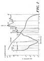
- Figure 1has a logarithmic scale respresenting the absorption coefficient in units of cm ⁇ 1 along the vertical axis and the incident energy wavelength in micrometers along the horizontal axis.
- the absorption of waterreaches a minimum at 0.5 micrometers so that it is necessary to use a higher power laser than is desirable to achieve sufficient power in the surgical area for material cutting and removal.
- the absorption lengthis very long (approximately 1 mm).
- scattering for these lasersis relatively high, causing difficulty in controlling the laser energy and a danger of tissue damage outside the surgical area due to scattering of the laser energy.
- laser sources of interestare those that lie in the wavelength range of approximately 1.4-2.2 micrometers. As shown in Figure 1, in this range, the energy absorption of water is relatively high whereas optical scattering is relatively low.
- Illustrative lasers which are useful with the present inventioncomprise Erbium-doped Yttrium Aluminum Garnet (YAG) with a wavelength of 1.55 micrometers, Erbium-doped Yttrium Lithium Fluoride (YLF) with a wavelength of 1.73 micrometers, Thulium-doped YAG with a wavelength of 1.88 micrometers, Holmium YLF with a wavelength of 2.06 micrometers and Holmium YAG at a wavelength of 2.1 micrometers.
- YAGErbium-doped Yttrium Aluminum Garnet
- YLFErbium-doped Yttrium Lithium Fluoride
- Thulium-doped YAGwith a wavelength of 1.88 micrometers
- the absorption of the laser energy produced by lasers in this latter group by wateris moderately high and, consequently, the absorption by biological tissues of such energy will also be relatively high.
- the absorption by wateris not as high as the absorption of CO and CO2 laser energy.
- the absorption lengthwill be longer for the lasers operating in the 1.4-2.2 micron range.
- the absorption length in the body for these latter lasersis about 200 microns. Therefore, it is still possible to operate satisfactorily even with 10-30 microns of blood between the fiber end and the surgical site.
- Figure 2is a plot of the absorption by plaque of electromagnetic energy versus wavelength for energy in the wavelength range of 0.2-2.2 micrometers. As shown in Figure 2, the absorption by plaque of electromagnetic energy reaches a minimum in the 0.8-1 micrometer wavelength range and generally increases with increasing wavelength in the wavelength region of 1-2.2 micrometers.
- the wavelength range produced by laser in the above-mentioned groupthe absorption by plaque is at a relatively high value.
- FIG. 3A schematic diagram of a typical solid-state laser construction is shown in Figure 3.
- the laser assemblyconsists of a laser crystal 1 and an excitation device such as a flashlamp 3.
- the laser crystalmust be cooled to cryogenic temperature to provide low laser-threshhold operation.
- Cryogenic coolingis typically provided by enclosing crystal 1 in a quartz or fused-silica jacket 4 through which liquid nitrogen is circulated.
- Liquid nitrogenenters jacket 4 by means of an inlet pipe 5 and leaves by means of an outlet pipe 6.
- the laser cavityis formed by a high-reflectivity concave mirror 10 and a partial reflector 12.
- the crystalis excited by optical pumping which is, in turn, accomplished by irradiating the crystal with light from a flashlamp 3.
- a flashlamp which is typically used with the inventive laser compositionsis a high pressure Xenon flashlamp.
- Lamp 3may also be surrounded by a quartz flow tube (not shown) through which coolant is pumped.
- Crystal 1 and flashlamp 3are enclosed in a reflector 2 which concentrates the flashlamp energy into the laser crystal.
- the inner surface of reflector 2is coated with a material chosen to have high-reflectivity at the pumping wavelength of the laser crystal - illustratively, aluminum or silver.
- a material chosen to have high-reflectivity at the pumping wavelength of the laser crystalillustratively, aluminum or silver.
- cryogenic solid-state lasersare conventional and described in a variety of sources; accordingly such construction will not be discussed further in detail herein.
- a more complete discussion of construction details of a typical cryogenic laseris set forth in an article entitled "TEM00 Mode Ho:YLF laser", N.P. Barnes, D.J. Gettemy, N.J. Levinos and J.E. Griggs, Society of Photo-Optical Instrumentation Engineers , Volume 190 - LASL Conference on Optics 1979, pp 297-304.
- Figure 4 of the drawingis a plot of the illustrative pulse shape developed by a laser in the preferred group when used in the "material removal” mode.
- Figure 4shows light intensity along the vertical axis increasing in the downward direction versus time increasing towards the right.
- the laser sourcehas been adjusted to produce an output pulse of relatively long time duration, most of the output energy is released within approximately 1 millisecond of the beginning of the pulse.
- lasers in the preferred laser groupexhibit a "spiking" phenomenon caused by internal relaxation-oscillations in the laser crystal.
- the spiking behaviorcauses local increases in laser intensity which have a large magnitude, but a very short time duration. Similar "spiking" behavior has been found advantageous when lasers are used to drill metals and other materials for industrial purposes and it is believed that such "spiking" behavior enhances the laser usefulness for biological material removal.
- FIG 5is a schematic diagram of a laser/catheter apparatus employing a solid state laser of the type shown in detail in Figure 3. More specifically, the infrared output energy of laser 21 is focused by a conventional focusing lens onto the end of the optical fiber which is held in a conventional fiber optic connector 24. Fiber optic connector 24 is, in turn, connected to a tube 27 which houses a single optical fiber. Tube 27 is connected to a conventional two-lumen catheter 30 by means of a bifurcation fitting 28.
- catheter 30has two lumens passing axially therethrough to its distal end 34 so that an optical fiber can pass through one lumen and transmit laser energy from fiber optic connector 24 to lens tip 34.
- the optical fiber which passes through the catheteris specially purified to reduce the hydroxyl ion concentration to a low level, thus preventing the laser energy which is transmitted down the fiber from being highly absorbed in the fiber material.
- a fiber which is suitable for use with the illustrative embodimentis a fused-silica optical fiber part no. 822W manufactured by the Spectran Corporation located in Sturbridge, Massachusetts.
- the mirrors and lenses (10, 12 and 22) which are used to form the IR laser cavity and focus the output energy beamare generally only reflective to energy with a wavelength falling within a narrow wavelength band and transparent to energy at other wavelengths. Consequently, the mirrors and lenses are transparent to visible light.
- An aiming laser 20(for example, a conventional helium-neon laser) which generates visible light may be placed in series with IR laser 21 to generate a visible light beam. This light beam may be used to align mirrors 10 and 12 and to adjust focussing lens 22 so that the optical fiber system can be aligned prior to performing surgery.
- the optical fibers used to transmit the IR energy from laser 21 to the surgical areacan also be used to transmit the visible light from the aiming laser 20 to the surgical area.
- the light produced by laser 20passes through the optical fiber in catheter 30 and can be used to aim the probe tip before laser 21 is turned on to perform the actual operation
- the second lumen in catheter 30is provided for transmission of a flushing fluid or to apply suction to the probe lens tip area to clear the area of blood during surgery.
- This latter lumenis connected through bifurcation fitting 28 to a second tube 29.
- Tube 29may illustratively be terminated by a standard Luer-Lok fitting 26 which allows connection of the catheter to injectors and standard flow fittings. Solutions injected into the catheter through tube 29 pass through the lumen in catheter 30 and exit at the distal end via a small orifice 32.
- Probe tip 34consists of a lens arrangement which forms the laser energy into a beam 36 which is used to perform the surgical operations.
- An enlarged view of the probe tipis shown in Figures 6 and 7.
- Holder 58has a precision-formed axial bore made up of two sections, including a large-diameter section 60 and a narrow-diameter section 63. Holder 58 may be made of glass, ceramic or other material capable of being formed to specified dimensions with precise tolerances.
- the fiberis first prepared as shown in Figure 7. More particularly, prior to insertion of fiber 18 into holder 58, a portion of buffer sheath 61 is removed, exposing a length of optically-conductive core 65. Care is taken when stripping buffer sheath 61 from the fiber not to damage the layer of reflective cladding 67 located on the surface of core 65. After stripping, fiber 18 is inserted into holder 58 so that core 65 extends into the small-diameter bore 63 and sheath 61 extends into the large-diameter bore 60. After fiber 18 has been inserted into holder 58, it may be fastened by epoxy cement to permanently affix the components. To complete the assembly, the end of fiber 18 which protrudes beyond surface 62 of holder 58 may be finished flush with the surface by grinding the assembly or by carefully cleaving the fiber.
- holder 58(with fiber 18 fastened inside) is mounted within a glass tube 51 to shield the assembly.
- the front surface, 62, of holder 58is spaced from the inner surface 142 of planar lens 144, which may be comprised of glass or sapphire, by means of a spacing ring 154.
- Ring 154may illustratively be made of radiopaque material so that the catheter tip can be located inside the patient by means of a fluoroscope.
- Glass tubing 51is bent over shoulder 68 of holder 58 to form a constricted end, 65, which holds the probe tip assembly together.
- a filler, 66which may be made of a plastic such as TEFLON (trademark of the DuPont corporation for polytetrafluoroethylene) fills the annular space between catheter body 30 and end 65 of glass tube 51.
- the outer diameter of the entire assembly from catheter body 30 to glass tube 51is substantially the same, providing a smooth, uniform surface along the entire length of the catheter as indicated in Figure 6.
- Figure 8shows a schematic diagram of a wire-guided, four-fiber catheter for use with the present invention.
- the laser systemis set up as previously described with the infrared laser 21 constructed in accordance with the above disclosure.
- a visible helium-neon aiming laser 20may also be used in line with laser 21 for aiming purposes as discussed with the single fiber catheter.
- the output of the infrared laser 21is directed towards a set of four mirrors 60a-68a arranged at a 45° angle with respect to the axis of beam 14.
- the first mirror, 60ahas a 25% reflective surface and directs approximately 1/4 of the energy to focusing lens 70.
- the second mirror of the set, 62ais a 33% reflector which directs 1/4 of the total energy to focusing lens 72.
- Mirror 64ais a 50% reflector which directs 1/4 of the total laser output to focusing lens 74.
- the last mirror in the set, mirror 68ais a 100% reflector which directs the remaining 1/4 of the total energy to focusing lens 78.
- Mirrors 60a-68a and lenses 70-78are conventional devices.
- Focusing lenses 70-78focus the output energy from IR laser 21 onto four fiber optic connectors ,80-88.
- Connectors 80-88are connected, respectively, to tubes 90-96 which are all connected, via a branch connector 102, to catheter 104.
- Each of tubes 90-96contains a single optical fiber which transmits 1/4 of the total laser output energy through the catheter body to the catheter tip 108.
- An additional tube 98is provided which is connected to branch fitting 102 and to a conventional Luer-Lok connector, 100. This latter tube is connected to a central lumen in catheter body 104 through which flushing solutions may be injected or through which a guide wire may be inserted through the catheter for purposes of guiding the catheter to the surgical area.
- Tip 108At catheter tip 108, the four optical fibers which pass through the catheter are arranged symmetrically so that the beams 110 overlap to illuminate a larger area. Tip 108 also has a hole on the centre thereof, through which guidewire 112 can protrude to direct the catheter to the proper location.
- Figures 9 and 10show detailed views of the illustrative four-fiber catheter tip.
- the four optical fibers 42 and the inner shaft 40 which holds the fibers,are held in a fiber holder 50 which is preferably formed from a radiopaque material such as stainless steel or platinum.
- Fiber holder 50is cylindrical and is provided with a central aperture, 54, which communicates with a lumen 34 of approximately the same size that passes through the center of the catheter body 104.
- Fiber holder 50is provided with & plurality of longitudinally extending holes 56 which extend through the wall of holder 50 and receive, in a snug fit, the distal ends of the fiber cores 42.
- the distal face 58a of the combined fiber cores 42 and holder 50is polished flat to butt flush against optically transparent cap 52.
- Cap 52is cylindrical and has the same outer diameter as catheter body 104 so that the two pieces define a smooth and continuous diameter.
- Cap 52may be formed of a transparent substance such as pyrex glass or sapphire and has an enlarged bore 62b extending in from its proximal end. Bore 62b terminates at its end to form internal shoulder 60.
- a smaller diameter central aperture, 64b,is formed in the distal end of cap 52 which aperture may have the same diameter as aperture 54 in fiber holder 50 and lumen 34 in catheter body 104 to provide a smooth and continuous lumen which opens at the distal tip of the catheter.
- the aperture 64b in tip 52may also be somewhat narrower than aperture 54 and lumen 34 as long as sufficient clearance is provided to accommodate a guidewire without adversely interfering with fluid flow and pressure measurements.
- Cap 52is secured by an epoxy adhesive (placed on its inner surface 62b) to the fiber holder 50 and also to the portion of the inner shaft 40 and fibers 42 which are disposed within the proximal end of the cap 52.
- the distal end of the catheter body 104is heat shrunk around the inner shaft 40 and fibers 42 to provide a smooth transition from cap 52 to catheter body 104.
- Figure 11illustrates the output beam pattern developed by a four-fiber catheter, such as that described above, in which the four fibers are arranged in two diametrically-opposed pairs.
- the beam pattern from each of the four fiber endsis defined by a cone formed by the ray lines 70 in Figure 11.
- the beam from each individual fiber 42is emitted from the distal face of the fiber 42 and enters the distal segment 72 of cap 52 through the face defining the shoulder 60.
- the beam from each fiberis divergent and, in the illustrative embodiment, may have a half-angle in the range of 6°-16°, depending on the numerical aperture of the fibers which are used to construct the catheter.
- FIGS 11A, 11B and 11Cillustrate the overall beam pattern (in cross-section) which is formed by the output of the four fibers as seen along image planes 11A, 11B and 11C in Figure 11.
- plane 11Awhich is located at the emission face 74 of cap 52, the four beams in the illustrative embodiment are still separate.
- plane 11Bthe diverging beams have spread further and have begun to overlap.
- the beamshave overlapped and define an envelop 73 having an outer diameter which is slightly greater than the outer diameter of the catheter body 104.
- beams 70will have overlapped to merge and cover a continuous pattern.
- such a mergerwill have occurred within a distance from the distal face 74 of tip 52 which is approximately equal to the outer diameter of catheter 104 (a typical diameter is 1.5 millimeters).
Landscapes
- Physics & Mathematics (AREA)
- Health & Medical Sciences (AREA)
- Surgery (AREA)
- Optics & Photonics (AREA)
- Life Sciences & Earth Sciences (AREA)
- Biomedical Technology (AREA)
- Medical Informatics (AREA)
- Nuclear Medicine, Radiotherapy & Molecular Imaging (AREA)
- Electromagnetism (AREA)
- Engineering & Computer Science (AREA)
- General Physics & Mathematics (AREA)
- Heart & Thoracic Surgery (AREA)
- Otolaryngology (AREA)
- Molecular Biology (AREA)
- Animal Behavior & Ethology (AREA)
- General Health & Medical Sciences (AREA)
- Public Health (AREA)
- Veterinary Medicine (AREA)
- Laser Surgery Devices (AREA)
- Radiation-Therapy Devices (AREA)
Description
- This invention relates to a laser catheter apparatus for generating and transmitting energy to a surgical site in a living body for the purposes of tissue removal or repair.
- While lasers have been used for many years for industrial purposes such as drilling and cutting materials, it is only recently that surgeons have begin to use lasers for surgical operations on living tissue. To this end, laser energy has been used to repair retinal tissue and to cauterize blood vessels in the stomach and colon.
- In many surgical situations, it is desirable to transmit laser energy down an optical fiber to the surgical location. If this can be done, the optical fiber can be included in a catheter which can be inserted into the body through a small opening, thus reducing the surgical trauma associated with the operation. In addition, the catheter can often be maneuvered to surgical sites which are so restricted that conventional scalpel surgery is difficult, if not impossible. For example, laser energy can be used to remove atherosclerotic plaque from the walls of the vasculature and to repair defects in small-diameter artery walls.
- A problem has been encountered with laser surgery in that prior art lasers which have been used for industrial purposes often have characteristics which are not well suited to percutaneous laser surgery. For example, a laser which is conventionally used for scientific purposes is an excimer laser which is a gas laser that operates with a gas mixture such as Argon-Fluorine, Krypton-Fluorine or Xenon-Fluorine. Another common industrial laser is the carbon dioxide or CO₂ laser.
- Both the excimer laser and the CO₂ laser have been used for surgical purposes with varying results. One problem with excimer lasers is that they produce output energy having a wavelength in the range 0.2-0.5 micrometers. Blood hemoglobin and proteins have a relatively high absorption of energy in this wavelength range and, thus, the output beam of an excimer laser has a very short absorption length in these materials (the absorption length is the distance in the materials over which the laser beam can travel before most of the energy is absorbed). Consequently, the surgical site in which these lasers are to be used must be cleared of blood prior to the operation, otherwise most of the laser energy will be absorbed by intervening blood before it reaches the surgical area. While the removal of blood is possible if surgery is performed on an open area it is often difficult if surgery is to be performed via a catheter located in an artery or vein.
- An additional problem with excimer lasers is that the output energy pulse developed by the laser is very short, typically about ten nanoseconds. In order to develop reasonable average power, pulses with extremely high peak power must be used. When an attempt is made to channel such a high peak power output into an optical fiber, the high peak power destroys the fiber. Thus, excimer lasers have a practical power limit which is relatively low. Consequently, when these lasers are used for biological tissue removal, the operation is slow and time consuming.
- The CO₂ laser has other drawbacks. This laser generates output energy with a wavelength on the order of 10 micrometers. At this wavelength, the absorption of blood hemoglobin is negligible but the absorption by water and tissue is relatively high. Scattering at this wavelength is also very low. Although the CO₂ laser possesses favorable characteristics for surgical applications in that it has low scattering and high absorption in tissue, it suffers from the same drawback as excimer lasers in that the absorption length is relatively short due to the high absorption of the laser energy in water. Thus, the surgical area must be cleared of blood prior to the operation.
- Unfortunately, the CO₂ laser also suffers from a serious additional problem. Due to the long wavelength, the output energy from the carbon dioxide laser cannot be presently transmitted down any optical fibres which are suitable for use in percutaneous surgery (present fibres which can transmit energy from a CO₂ laser are either composed of toxic materials, are soluble in water or are not readily bendable, or possess a combination of the previous problems) and, thus, the laser is only suitable for operations in which the laser energy can be either applied directly to the surgical area or applied by means of an optical system comprised of prisms or mirrors.
- David N. Kaye describes in his article "The happy merger of fibre optics and lasers" two methods of combining fibre optics and lasers as a tool to reach locations which are not accessible with large fixed lasers. Among several laser/fibre combinations an Er:Glass laser for medical and industrial use is proposed. This laser emits a pulsed radiation of 1.54 µm so as to eliminate retinal eye damage. Most of the lasers described operate in continuous wave mode so they cannot be used for the successful removal of plaque. References are also made to several materials which can be made to lase at various wavelengths but the only use of the equipment described is for the treatment of the eye rather than for plaque removal deep within the body. Indeed, none of the equipment described could be used for this purpose.
- GB-A-2017506 discloses a laser tunnelling device in which a thrombus in a blood vessel is destroyed by the use of laser light fed through an optical fibre received in a catheter inserted into a blood vessel. However, there is no discussion or suggestion in this reference that atherosclerotic plaque could be removed by this method, and there is no suggestion of the parameters required to achieve such plaque removal.
- It is an object of the present invention to provide a laser catheter which is capable of providing laser energy that can be transmitted through an optical fibre under such conditions as to achieve plaque removal.
- In accordance with the present invention there is provided a laser catheter apparatus for surgically removing atherosclerotic plaque from a surgical site within the body, comprising a flexible catheter member, a laser energy source and an optical fibre located within a lumen defined within the catheter member, the optical fibre being composed of a substantially non-toxic material and being tolerant to the operation of the laser source, wherein the output of the laser source is directed into the proximal end of the optical fibre, propagated along the optical fibre, and is directable by means attached to the distal end of the optical fibre to the surgical site, the catheter member and optical fibre being sufficiently flexible and being dimensioned to be passed from without the body, into and along a vein or artery, to the surgical site, characterised in that the laser source operates in a pulsed mode with pulses of a duration in a range of 0.2-5 milliseconds and a wavelength range of 1.4-2.2µm whereby to provide an effective removal of artherosclerotic plaque.
- Illustrative laser sources operating in the wavelength range of 1.4-2.2 micrometers are Holmium-doped YAG, Holmium-doped YLF, Erbium-doped YAG, Erbium-doped YLF and Thulium-doped YAG lasers.
- Preferably, the above-noted lasers are used with a specially-treated silica fibre that has been purified to reduce the concentration of hydroxyl (OH-) ions.
- The laser source is preferably operated such that the peak power of the laser pulse is approximately 1 kilowatt. This amount of power can easily be tolerated by the silica fibre, but is sufficient for rapid material removal. With a repetition rate in the range of 1-10 hertz, the average power delivered to a surgical site by such a laser will be under 10 watts.
- Preferred aspects and embodiments of the invention are defined and described in the dependent claims 2-11, attached hereto.
- The invention will now be described, by way of example only, with reference to the accompanying drawings, in which :
- Figure 1 shows a sketch of absorption of electromagnetic energy versus wavelength and electromagnetic energy scattering versus wavelength.
- Figure 2 shows an absorption versus wavelength plot for atherosclerotic plaque obtained in a carotid endarterectomy with the region of interest for the inventive laser sources (1.4-2.2 micrometers) outlined.
- Figure 3 of the drawing is a schematic diagram of a typical solid state laser construction used in the inventive laser sources.
- Figure 4 of the drawing is a plot of laser output intnsity versus time for a typical pulse shape developed by a laser shown in Figure 3 when used for tissue removal.
- Figure 5 is a schematic diagram of a laser catheter which employs a single optical fiber for transmitting laser energy to a surgical location.
- Figure 6 of the drawing is an enlarged cross-section of the probe tip the single fiber catheter shown in Figure 5.
- Figure 7 of the drawing shows the manner in which the fiber is inserted into the fiber holder.
- Figure 8 is a schematic diagram of a wire-guided catheter which employs four optical fibers to increase the area which can be irradiated with the laser light.
- Figure 9 and 10 of the drawing show an enlarged cross-sectional view of the probe tip of the catheter shown in Figure 8 showing the four optical fibers.
- Figure 11 of the drawing is a schematic diagram of the beam pattern produced by the four-fibercatheter at the surgical location.
- The absorption and scattering characteristics versus output wavelength of a plurality of known laser systems are shown in Figure 1. Figure 1 has a logarithmic scale respresenting the absorption coefficient in units of cm⁻¹ along the vertical axis and the incident energy wavelength in micrometers along the horizontal axis.
- From Figure 1, it can be seen that excimer laser systems which utilize conventional gas mixtures, such as Argon-Fluorine, Krypton-Fluorine and Xenon-Fluorine, and Argon gas lasers produce output energy which falls in the 0.2-0.5 micrometer wavelength region. In this region, the absorption of blood hemoglobin and proteins is very high. Consequently, the absorption length is very short (about 5-10 microns) and virtually no blood can be present between the fiber end and the surgical site during the operation. Thus, it is necessary to remove blood from the surgical area when these lasers are used for surgical purposes.
- In addition, for lasers such as Argon, the absorption of water reaches a minimum at 0.5 micrometers so that it is necessary to use a higher power laser than is desirable to achieve sufficient power in the surgical area for material cutting and removal. Also, due to the low absorption of the laser output in water and hemoglobin, the absorption length is very long (approximately 1 mm). In addition, scattering for these lasers is relatively high, causing difficulty in controlling the laser energy and a danger of tissue damage outside the surgical area due to scattering of the laser energy.
- At the other end of the wavelength spectrum shown in Figure 1 are carbon monoxide and carbon dioxide lasers producing outputs at 5 and 10 micrometers, respectively. At these wavelengths scattering is negligible and absorption by water and tissue is relatively high and thus both lasers have good surgical properties. Unfortunately, due to the high absorption of water, the absorption length is relatively short (about 20 microns). Further, silica-based optical fibers in present use which are suitable for percutaneous surgical use have a practical "cutoff" in transmission which occurs approximately at 2.3 micrometers, and, thus, the output energy from carbon monoxide and carbon dioxide lasers cannot be transmitted through such an optical fiber.
- In accordance with the invention, laser sources of interest are those that lie in the wavelength range of approximately 1.4-2.2 micrometers. As shown in Figure 1, in this range, the energy absorption of water is relatively high whereas optical scattering is relatively low. Illustrative lasers which are useful with the present invention comprise Erbium-doped Yttrium Aluminum Garnet (YAG) with a wavelength of 1.55 micrometers, Erbium-doped Yttrium Lithium Fluoride (YLF) with a wavelength of 1.73 micrometers, Thulium-doped YAG with a wavelength of 1.88 micrometers, Holmium YLF with a wavelength of 2.06 micrometers and Holmium YAG at a wavelength of 2.1 micrometers. The absorption of the laser energy produced by lasers in this latter group by water is moderately high and, consequently, the absorption by biological tissues of such energy will also be relatively high. However, the absorption by water is not as high as the absorption of CO and CO₂ laser energy. Thus, the absorption length will be longer for the lasers operating in the 1.4-2.2 micron range. Typically, the absorption length in the body for these latter lasers is about 200 microns. Therefore, it is still possible to operate satisfactorily even with 10-30 microns of blood between the fiber end and the surgical site.
- Of particular interest is the absorption of the laser energy by atherosclerotic plaque, since an important use of laser catheter systems is angioplasty, particularly the clearing of blocked arteries. Figure 2 is a plot of the absorption by plaque of electromagnetic energy versus wavelength for energy in the wavelength range of 0.2-2.2 micrometers. As shown in Figure 2, the absorption by plaque of electromagnetic energy reaches a minimum in the 0.8-1 micrometer wavelength range and generally increases with increasing wavelength in the wavelength region of 1-2.2 micrometers.
- In the wavelength range from 1.4-2.2 micrometers, the wavelength range produced by laser in the above-mentioned group, the absorption by plaque is at a relatively high value.
- A schematic diagram of a typical solid-state laser construction is shown in Figure 3. The laser assembly consists of a
laser crystal 1 and an excitation device such as a flashlamp 3. Typically, for the crystal compositions disclosed above, the laser crystal must be cooled to cryogenic temperature to provide low laser-threshhold operation. Cryogenic cooling is typically provided by enclosingcrystal 1 in a quartz or fused-silica jacket 4 through which liquid nitrogen is circulated. Liquid nitrogen entersjacket 4 by means of aninlet pipe 5 and leaves by means of anoutlet pipe 6. The laser cavity is formed by a high-reflectivityconcave mirror 10 and apartial reflector 12. - Generally, the crystal is excited by optical pumping which is, in turn, accomplished by irradiating the crystal with light from a flashlamp 3. A flashlamp which is typically used with the inventive laser compositions is a high pressure Xenon flashlamp. Lamp 3 may also be surrounded by a quartz flow tube (not shown) through which coolant is pumped.
Crystal 1 and flashlamp 3 are enclosed in areflector 2 which concentrates the flashlamp energy into the laser crystal. To maximize energy transfer from lamp 3 tocrystal 1, the inner surface ofreflector 2 is coated with a material chosen to have high-reflectivity at the pumping wavelength of the laser crystal - illustratively, aluminum or silver. In order to provide thermal insulation to prevent condensation on the system optics, it may be necessary to evacuate the interior ofreflector 2 or to provide a vacuum jacket aroundcrystal 1.- The construction of cryogenic solid-state lasers is conventional and described in a variety of sources; accordingly such construction will not be discussed further in detail herein. A more complete discussion of construction details of a typical cryogenic laser is set forth in an article entitled "TEM₀₀ Mode Ho:YLF laser", N.P. Barnes, D.J. Gettemy, N.J. Levinos and J.E. Griggs,Society of Photo-Optical Instrumentation Engineers, Volume 190 - LASL Conference on Optics 1979, pp 297-304.
- Figure 4 of the drawing is a plot of the illustrative pulse shape developed by a laser in the preferred group when used in the "material removal" mode. Figure 4 shows light intensity along the vertical axis increasing in the downward direction versus time increasing towards the right. Although, as shown in Figure 4, the laser source has been adjusted to produce an output pulse of relatively long time duration, most of the output energy is released within approximately 1 millisecond of the beginning of the pulse. It should also be noted,as illustrated in Figure 4, that lasers in the preferred laser group exhibit a "spiking" phenomenon caused by internal relaxation-oscillations in the laser crystal. The spiking behavior causes local increases in laser intensity which have a large magnitude, but a very short time duration. Similar "spiking" behavior has been found advantageous when lasers are used to drill metals and other materials for industrial purposes and it is believed that such "spiking" behavior enhances the laser usefulness for biological material removal.
- Figure 5 is a schematic diagram of a laser/catheter apparatus employing a solid state laser of the type shown in detail in Figure 3. More specifically, the infrared output energy of
laser 21 is focused by a conventional focusing lens onto the end of the optical fiber which is held in a conventionalfiber optic connector 24.Fiber optic connector 24 is, in turn, connected to atube 27 which houses a single optical fiber.Tube 27 is connected to a conventional two-lumen catheter 30 by means of abifurcation fitting 28. - Illustratively,
catheter 30 has two lumens passing axially therethrough to itsdistal end 34 so that an optical fiber can pass through one lumen and transmit laser energy fromfiber optic connector 24 tolens tip 34. As previously mentioned, the optical fiber which passes through the catheter is specially purified to reduce the hydroxyl ion concentration to a low level, thus preventing the laser energy which is transmitted down the fiber from being highly absorbed in the fiber material. A fiber which is suitable for use with the illustrative embodiment is a fused-silica optical fiber part no. 822W manufactured by the Spectran Corporation located in Sturbridge, Massachusetts. - Advantageously, the mirrors and lenses (10, 12 and 22) which are used to form the IR laser cavity and focus the output energy beam are generally only reflective to energy with a wavelength falling within a narrow wavelength band and transparent to energy at other wavelengths. Consequently, the mirrors and lenses are transparent to visible light. An aiming laser 20 (for example, a conventional helium-neon laser) which generates visible light may be placed in series with
IR laser 21 to generate a visible light beam. This light beam may be used to alignmirrors lens 22 so that the optical fiber system can be aligned prior to performing surgery. - Also, the optical fibers used to transmit the IR energy from
laser 21 to the surgical area can also be used to transmit the visible light from the aiminglaser 20 to the surgical area. Thus, when the inventive apparatus is used in performing surgery where the surgical area is visible to the surgeon, the light produced bylaser 20 passes through the optical fiber incatheter 30 and can be used to aim the probe tip beforelaser 21 is turned on to perform the actual operation - The second lumen in
catheter 30 is provided for transmission of a flushing fluid or to apply suction to the probe lens tip area to clear the area of blood during surgery. This latter lumen is connected through bifurcation fitting 28 to asecond tube 29.Tube 29 may illustratively be terminated by a standard Luer-Lok fitting 26 which allows connection of the catheter to injectors and standard flow fittings. Solutions injected into the catheter throughtube 29 pass through the lumen incatheter 30 and exit at the distal end via asmall orifice 32. - Probe
tip 34 consists of a lens arrangement which forms the laser energy into abeam 36 which is used to perform the surgical operations. An enlarged view of the probe tip is shown in Figures 6 and 7. - To ensure that the distal end of
optical fiber 18 is spaced and oriented in a precise position with respect to the end of the probe,fiber 18 is mounted in a high-precision holder 58 which has a reduceddiameter end 64 that forms ashoulder 68.Shoulder 68, as will hereinafter be described, is used to hold the probe tip assembly together.Holder 58 has a precision-formed axial bore made up of two sections, including a large-diameter section 60 and a narrow-diameter section 63.Holder 58 may be made of glass, ceramic or other material capable of being formed to specified dimensions with precise tolerances. - In order to attach
holder 58 to the end offiber 18, the fiber is first prepared as shown in Figure 7. More particularly, prior to insertion offiber 18 intoholder 58, a portion of buffer sheath 61 is removed, exposing a length of optically-conductive core 65. Care is taken when stripping buffer sheath 61 from the fiber not to damage the layer ofreflective cladding 67 located on the surface ofcore 65. After stripping,fiber 18 is inserted intoholder 58 so thatcore 65 extends into the small-diameter bore 63 and sheath 61 extends into the large-diameter bore 60. Afterfiber 18 has been inserted intoholder 58, it may be fastened by epoxy cement to permanently affix the components. To complete the assembly, the end offiber 18 which protrudes beyondsurface 62 ofholder 58 may be finished flush with the surface by grinding the assembly or by carefully cleaving the fiber. - Referring to Figure 6, holder 58 (with
fiber 18 fastened inside) is mounted within aglass tube 51 to shield the assembly. The front surface, 62, ofholder 58 is spaced from theinner surface 142 ofplanar lens 144, which may be comprised of glass or sapphire, by means of aspacing ring 154.Ring 154 may illustratively be made of radiopaque material so that the catheter tip can be located inside the patient by means of a fluoroscope. Glass tubing 51 is bent overshoulder 68 ofholder 58 to form a constricted end, 65, which holds the probe tip assembly together. A filler, 66, which may be made of a plastic such as TEFLON (trademark of the DuPont corporation for polytetrafluoroethylene) fills the annular space betweencatheter body 30 and end 65 ofglass tube 51. The outer diameter of the entire assembly fromcatheter body 30 toglass tube 51 is substantially the same, providing a smooth, uniform surface along the entire length of the catheter as indicated in Figure 6.- Figure 8 shows a schematic diagram of a wire-guided, four-fiber catheter for use with the present invention. The laser system is set up as previously described with the
infrared laser 21 constructed in accordance with the above disclosure. A visible helium-neon aiming laser 20 may also be used in line withlaser 21 for aiming purposes as discussed with the single fiber catheter. The output of theinfrared laser 21 is directed towards a set of four mirrors 60a-68a arranged at a 45° angle with respect to the axis ofbeam 14. - The first mirror, 60a, has a 25% reflective surface and directs approximately 1/4 of the energy to focusing
lens 70. The second mirror of the set, 62a, is a 33% reflector which directs 1/4 of the total energy to focusinglens 72.Mirror 64a is a 50% reflector which directs 1/4 of the total laser output to focusinglens 74. The last mirror in the set,mirror 68a, is a 100% reflector which directs the remaining 1/4 of the total energy to focusinglens 78. Mirrors 60a-68a and lenses 70-78 are conventional devices. - Focusing lenses 70-78 focus the output energy from
IR laser 21 onto four fiber optic connectors ,80-88. Connectors 80-88 are connected, respectively, to tubes 90-96 which are all connected, via a branch connector 102, tocatheter 104. Each of tubes 90-96 contains a single optical fiber which transmits 1/4 of the total laser output energy through the catheter body to thecatheter tip 108. Anadditional tube 98 is provided which is connected to branch fitting 102 and to a conventional Luer-Lok connector, 100. This latter tube is connected to a central lumen incatheter body 104 through which flushing solutions may be injected or through which a guide wire may be inserted through the catheter for purposes of guiding the catheter to the surgical area. - At
catheter tip 108, the four optical fibers which pass through the catheter are arranged symmetrically so that the beams 110 overlap to illuminate a larger area.Tip 108 also has a hole on the centre thereof, through which guidewire 112 can protrude to direct the catheter to the proper location. - Figures 9 and 10 show detailed views of the illustrative four-fiber catheter tip. The four
optical fibers 42 and theinner shaft 40 which holds the fibers, are held in afiber holder 50 which is preferably formed from a radiopaque material such as stainless steel or platinum.Fiber holder 50 is cylindrical and is provided with a central aperture, 54, which communicates with alumen 34 of approximately the same size that passes through the center of thecatheter body 104.Fiber holder 50 is provided with & plurality of longitudinally extendingholes 56 which extend through the wall ofholder 50 and receive, in a snug fit, the distal ends of thefiber cores 42. The distal face 58a of the combinedfiber cores 42 andholder 50 is polished flat to butt flush against opticallytransparent cap 52. Cap 52 is cylindrical and has the same outer diameter ascatheter body 104 so that the two pieces define a smooth and continuous diameter.Cap 52 may be formed of a transparent substance such as pyrex glass or sapphire and has an enlarged bore 62b extending in from its proximal end. Bore 62b terminates at its end to forminternal shoulder 60. A smaller diameter central aperture, 64b, is formed in the distal end ofcap 52 which aperture may have the same diameter asaperture 54 infiber holder 50 andlumen 34 incatheter body 104 to provide a smooth and continuous lumen which opens at the distal tip of the catheter. However, theaperture 64b intip 52 may also be somewhat narrower thanaperture 54 andlumen 34 as long as sufficient clearance is provided to accommodate a guidewire without adversely interfering with fluid flow and pressure measurements.Cap 52 is secured by an epoxy adhesive (placed on its inner surface 62b) to thefiber holder 50 and also to the portion of theinner shaft 40 andfibers 42 which are disposed within the proximal end of thecap 52. The distal end of thecatheter body 104 is heat shrunk around theinner shaft 40 andfibers 42 to provide a smooth transition fromcap 52 tocatheter body 104.- More complete construction details of a four-fiber catheter suitable for use with the illustrative embodiment are given in US-A-4850351 entitled "Wire Guided Laser Catheter", filed on May 22, 1985 by Stephen J. Herman, Laurence A. Roth, Edward L. Sinofsky and Douglas W. Dickinson, Jr.
- Figure 11 illustrates the output beam pattern developed by a four-fiber catheter, such as that described above, in which the four fibers are arranged in two diametrically-opposed pairs. The beam pattern from each of the four fiber ends is defined by a cone formed by the
ray lines 70 in Figure 11. The beam from eachindividual fiber 42 is emitted from the distal face of thefiber 42 and enters thedistal segment 72 ofcap 52 through the face defining theshoulder 60. The beam from each fiber is divergent and, in the illustrative embodiment, may have a half-angle in the range of 6°-16°, depending on the numerical aperture of the fibers which are used to construct the catheter. - The diverging beam from each of the
fibers 42 exits from thedistal emission face 74 at the end ofcap 52. Figures 11A, 11B and 11C illustrate the overall beam pattern (in cross-section) which is formed by the output of the four fibers as seen along image planes 11A, 11B and 11C in Figure 11. At plane 11A, which is located at theemission face 74 ofcap 52, the four beams in the illustrative embodiment are still separate. At plane 11B, the diverging beams have spread further and have begun to overlap. At the plane indicated as 11C, the beams have overlapped and define anenvelop 73 having an outer diameter which is slightly greater than the outer diameter of thecatheter body 104. Preferably, at plane 11C, beams 70 will have overlapped to merge and cover a continuous pattern. Illustratively, such a merger will have occurred within a distance from thedistal face 74 oftip 52 which is approximately equal to the outer diameter of catheter 104 (a typical diameter is 1.5 millimeters).
Claims (11)
- A laser catheter apparatus for surgically removing atherosclerotic plaque from a surgical site within the body, comprising a flexible catheter member (30), a laser energy source (21) and an optical fibre (42) located within a lumen defined within the catheter member (30), the optical fibre (42) being composed of a substantially non-toxic material and being tolerant to the operation of the laser source, wherein the output of the laser source (21) is directed into the proximal end (24) of the optical fibre (42), propagated along the optical fibre (42), and is directable by means (58) attached to the distal end of the optical fibre to the surgical site, the catheter member (30) and optical fibre (42) being sufficiently flexible and being dimensioned to be passed from without the body, into and along a vein or artery, to the surgical site,characterised in that the laser source (21) operates in a pulsed mode with pulses of a duration in a range of 0.2-5 milliseconds and a wavelength range of 1.4-2.2µm whereby to provide an effective removal of artherosclerotic plaque.
- A laser catheter apparatus as claimed in claim 1 characterised by an output of approximately 1-2 joules per pulse.
- A laser catheter apparatus as claimed in any of the preceding claims, characterised in that the laser energy source (21) operates at a pulse rate in the range of from 1 to 10 hertz.
- A laser catheter apparatus as claimed in any of the preceding claims, characterised in that the optical fibre (42) comprises a silica fibre in which the hydroxyl ion content is reduced sufficiently to allow transmission of the laser energy.
- A laser catheter apparatus as claimed in any of the preceding claims characterised by further comprising a focussing lens (22) for directing the output of said laser source onto the proximal end of said optical fibre, and a lens (144) attached to the distal end of the optical fibre for directing laser energy propagating down said fibre to a surgical site.
- A laser catheter apparatus as claimed in any of the preceding claims characterised by further comprising additional optical fibres, a plurality of partially reflective mirrors (60a, 62a, 64a, 68a) arranged in series along the axis of the output from the laser source for directing a portion of said output to the proximal ends of the optical fibres, and a plurality of focussing lenses (70,72,74,78) positioned between the mirrors and the proximal ends of the fibres for focussing portions of said laser output to the proximal ends of the fibres, and means (108) attached to the distal end of the optical fares for directing laser energy propagating down said fibres to a surgical site, said directing means holding the fibres in a fixed position relative to one another so that optical beams emanating from the distal ends of the fibres overlap to cover an area at least equal to the diameter of said catheter.
- A laser catheter apparatus as claimed in any of the preceding claims characterised in that the output energy is spread over a 1.5 mm diameter surgical site.
- A laser catheter apparatus as claimed in any of the preceding claims characterised by further comprising an aiming laser (20) source generating visible light output and means (10,12) for directing said visible light output through the laser source and the optical fibre to align said laser and said fibre and to visually illuminate the surgical site.
- A laser catheter apparatus as claimed in any of the preceding claims characterised by further comprising a fibre optic connector (24,80,82,84,88) affixed to the proximal end of the or each fibre for holding said fibre.
- A laser catheter apparatus as claimed in any of the preceding claims characterised in that the catheter member (30) has an additional lumen passing therethrough, said additional lumen having an opening at the proximal and distal ends for communicating with said surgical site.
- A laser catheter apparatus as claimed in any of the preceding claims characterised in that the laser source comprises a Holmium-doped Yttrium-Aluminum-Garnet laser, an Erbium-doped Yttrium-Aluminum-Garnet laser, a Holmium-doped Yttrium-lithium-Flouride laser, an Erbium-doped Yttrium-Lithium-Fluoride laser or a Thulium-doped Yttrium-Aluminum-Garnet laser.
Applications Claiming Priority (2)
| Application Number | Priority Date | Filing Date | Title |
|---|---|---|---|
| US76118885A | 1985-07-31 | 1985-07-31 | |
| US761188 | 1985-07-31 |
Publications (2)
| Publication Number | Publication Date |
|---|---|
| EP0214712A1 EP0214712A1 (en) | 1987-03-18 |
| EP0214712B1true EP0214712B1 (en) | 1992-09-02 |
Family
ID=25061440
Family Applications (1)
| Application Number | Title | Priority Date | Filing Date |
|---|---|---|---|
| EP86303982AExpired - LifetimeEP0214712B1 (en) | 1985-07-31 | 1986-05-27 | Infrared laser catheter apparatus |
Country Status (7)
| Country | Link |
|---|---|
| US (2) | US5843073A (en) |
| EP (1) | EP0214712B1 (en) |
| JP (1) | JPS6234553A (en) |
| AU (1) | AU623117B2 (en) |
| CA (1) | CA1275450C (en) |
| DE (1) | DE3686621T2 (en) |
| ES (3) | ES8900225A1 (en) |
Cited By (10)
| Publication number | Priority date | Publication date | Assignee | Title |
|---|---|---|---|---|
| US7935108B2 (en) | 1999-07-14 | 2011-05-03 | Cardiofocus, Inc. | Deflectable sheath catheters |
| US8025661B2 (en) | 1994-09-09 | 2011-09-27 | Cardiofocus, Inc. | Coaxial catheter instruments for ablation with radiant energy |
| US8078261B2 (en) | 2005-09-13 | 2011-12-13 | Children's Medical Center Corporation | Light-guided transluminal catheter |
| US8152795B2 (en) | 1999-07-14 | 2012-04-10 | Cardiofocus, Inc. | Method and device for cardiac tissue ablation |
| US8540704B2 (en) | 1999-07-14 | 2013-09-24 | Cardiofocus, Inc. | Guided cardiac ablation catheters |
| US8696653B2 (en) | 2009-10-02 | 2014-04-15 | Cardiofocus, Inc. | Cardiac ablation system with pulsed aiming light |
| US8702688B2 (en) | 2009-10-06 | 2014-04-22 | Cardiofocus, Inc. | Cardiac ablation image analysis system and process |
| US8900219B2 (en) | 1999-07-14 | 2014-12-02 | Cardiofocus, Inc. | System and method for visualizing tissue during ablation procedures |
| US8954134B2 (en) | 2005-09-13 | 2015-02-10 | Children's Medical Center Corporation | Light-guided transluminal catheter |
| US9033961B2 (en) | 1999-07-14 | 2015-05-19 | Cardiofocus, Inc. | Cardiac ablation catheters for forming overlapping lesions |
Families Citing this family (188)
| Publication number | Priority date | Publication date | Assignee | Title |
|---|---|---|---|---|
| US5470330A (en)* | 1984-12-07 | 1995-11-28 | Advanced Interventional Systems, Inc. | Guidance and delivery system for high-energy pulsed laser light |
| US4732448A (en)* | 1984-12-07 | 1988-03-22 | Advanced Interventional Systems, Inc. | Delivery system for high-energy pulsed ultraviolet laser light |
| US4850351A (en)* | 1985-05-22 | 1989-07-25 | C. R. Bard, Inc. | Wire guided laser catheter |
| EP0214712B1 (en)* | 1985-07-31 | 1992-09-02 | C.R. Bard, Inc. | Infrared laser catheter apparatus |
| US4917084A (en)* | 1985-07-31 | 1990-04-17 | C. R. Bard, Inc. | Infrared laser catheter system |
| US4854315A (en)* | 1987-06-25 | 1989-08-08 | Stack Richard S | Laser catheter |
| IL84367A (en)* | 1987-11-04 | 1994-02-27 | Amcor Ltd | Apparatus for use in radiation therapy |
| US4852567A (en)* | 1988-01-21 | 1989-08-01 | C. R. Bard, Inc. | Laser tipped catheter |
| EP0357760B1 (en)* | 1988-03-14 | 1993-05-26 | American Dental Technologies, Inc. | Dental laser |
| US5147354B1 (en)* | 1988-08-19 | 1997-10-14 | Coherent Inc | Mid-infrared laser endoscope |
| US5037421A (en)* | 1989-10-06 | 1991-08-06 | Coherent, Inc., Medical Group | Mid-infrared laser arthroscopic procedure |
| EP0368512A3 (en)* | 1988-11-10 | 1990-08-08 | Premier Laser Systems, Inc. | Multiwavelength medical laser system |
| US5263951A (en)* | 1989-04-21 | 1993-11-23 | Kerus Medical Systems | Correction of the optical focusing system of the eye using laser thermal keratoplasty |
| US5152759A (en)* | 1989-06-07 | 1992-10-06 | University Of Miami, School Of Medicine, Dept. Of Ophthalmology | Noncontact laser microsurgical apparatus |
| JP2882814B2 (en)* | 1989-08-24 | 1999-04-12 | 株式会社エス・エル・ティ・ジャパン | Laser irradiation equipment |
| US5032123A (en)* | 1989-12-28 | 1991-07-16 | Cordis Corporation | Laser catheter with radially divergent treatment beam |
| US5129895A (en)* | 1990-05-16 | 1992-07-14 | Sunrise Technologies, Inc. | Laser sclerostomy procedure |
| US5725522A (en)* | 1990-06-15 | 1998-03-10 | Rare Earth Medical, Inc. | Laser suturing of biological materials |
| US5071417A (en)* | 1990-06-15 | 1991-12-10 | Rare Earth Medical Lasers, Inc. | Laser fusion of biological materials |
| US5540677A (en)* | 1990-06-15 | 1996-07-30 | Rare Earth Medical, Inc. | Endoscopic systems for photoreactive suturing of biological materials |
| US5197470A (en)* | 1990-07-16 | 1993-03-30 | Eastman Kodak Company | Near infrared diagnostic method and instrument |
| US6342053B1 (en) | 1990-07-23 | 2002-01-29 | Laser Biotech, Inc. | Apparatus for cornea reshaping |
| ATE190733T1 (en)* | 1990-08-01 | 2000-04-15 | Diomed Ltd | HIGH POWER LIGHT SOURCE |
| AU647533B2 (en)* | 1990-10-16 | 1994-03-24 | Summit Technology, Inc. | Laser thermokeratoplasty methods and apparatus |
| US5163933A (en)* | 1990-10-22 | 1992-11-17 | Cedars-Sinai Medical Center | Prosthetic joint replacement procedure using excimer laser |
| US5688261A (en)* | 1990-11-07 | 1997-11-18 | Premier Laser Systems, Inc. | Transparent laser surgical probe |
| EP0578756B1 (en)* | 1991-04-04 | 2000-08-30 | Premier Laser Systems, Inc. | Laser surgical probe |
| US5722970A (en)* | 1991-04-04 | 1998-03-03 | Premier Laser Systems, Inc. | Laser surgical method using transparent probe |
| DE59208545D1 (en)* | 1991-10-30 | 1997-07-03 | Feichtinger Wilfried Dr | Micromanipulatory method and device for use in in vitro fertilization |
| AU678967B2 (en)* | 1992-04-10 | 1997-06-19 | Premier Laser Systems, Inc. | Apparatus and method for performing eye surgery |
| US6315772B1 (en) | 1993-09-24 | 2001-11-13 | Transmedica International, Inc. | Laser assisted pharmaceutical delivery and fluid removal |
| US5643252A (en)* | 1992-10-28 | 1997-07-01 | Venisect, Inc. | Laser perforator |
| US5643253A (en)* | 1995-06-06 | 1997-07-01 | Rare Earth Medical, Inc. | Phototherapy apparatus with integral stopper device |
| US5632767A (en)* | 1994-09-09 | 1997-05-27 | Rare Earth Medical, Inc. | Loop diffusers for diffusion of optical radiation |
| US5637877A (en)* | 1995-06-06 | 1997-06-10 | Rare Earth Medical, Inc. | Ultraviolet sterilization of instrument lumens |
| US5908415A (en)* | 1994-09-09 | 1999-06-01 | Rare Earth Medical, Inc. | Phototherapy methods and apparatus |
| JPH08106817A (en)* | 1994-10-05 | 1996-04-23 | Kawasaki Heavy Ind Ltd | Wiring mechanism |
| DE4443964C1 (en)* | 1994-12-09 | 1996-04-04 | Schwarzmaier Hans Joachim Dr | Laser appts. for irradiation of human body tissue |
| US5954713A (en)* | 1996-07-12 | 1999-09-21 | Newman; Fredric A. | Endarterectomy surgical instruments and procedure |
| US6443974B1 (en) | 1996-07-28 | 2002-09-03 | Biosense, Inc. | Electromagnetic cardiac biostimulation |
| US6517532B1 (en) | 1997-05-15 | 2003-02-11 | Palomar Medical Technologies, Inc. | Light energy delivery head |
| US8182473B2 (en) | 1999-01-08 | 2012-05-22 | Palomar Medical Technologies | Cooling system for a photocosmetic device |
| ES2226133T3 (en) | 1997-05-15 | 2005-03-16 | Palomar Medical Technologies, Inc. | DERMATOLOGICAL TREATMENT DEVICE. |
| ES2245506T3 (en) | 1998-03-12 | 2006-01-01 | Palomar Medical Technologies, Inc. | ELECTROMAGNETIC RADIATION APPLICATION SYSTEM ON SKIN. |
| US6053909A (en)* | 1998-03-27 | 2000-04-25 | Shadduck; John H. | Ionothermal delivery system and technique for medical procedures |
| US8016823B2 (en) | 2003-01-18 | 2011-09-13 | Tsunami Medtech, Llc | Medical instrument and method of use |
| US7892229B2 (en) | 2003-01-18 | 2011-02-22 | Tsunami Medtech, Llc | Medical instruments and techniques for treating pulmonary disorders |
| DE19823947A1 (en)* | 1998-05-28 | 1999-12-02 | Baasel Carl Lasertech | Method and device for superficial heating of tissue |
| IL124722A0 (en)* | 1998-06-02 | 1999-01-26 | Oron Amir | Ischemia laser treatment |
| US6059820A (en) | 1998-10-16 | 2000-05-09 | Paradigm Medical Corporation | Tissue cooling rod for laser surgery |
| US6214035B1 (en)* | 1999-03-23 | 2001-04-10 | Jackson Streeter | Method for improving cardiac microcirculation |
| US6224566B1 (en)* | 1999-05-04 | 2001-05-01 | Cardiodyne, Inc. | Method and devices for creating a trap for confining therapeutic drugs and/or genes in the myocardium |
| US6269108B1 (en)* | 1999-05-26 | 2001-07-31 | University Of Central Florida | Multi-wavelengths infrared laser |
| US6738661B1 (en) | 1999-10-22 | 2004-05-18 | Biosynergetics, Inc. | Apparatus and methods for the controllable modification of compound concentration in a tube |
| US6440125B1 (en) | 2000-01-04 | 2002-08-27 | Peter Rentrop | Excimer laser catheter |
| US7549987B2 (en) | 2000-12-09 | 2009-06-23 | Tsunami Medtech, Llc | Thermotherapy device |
| US9433457B2 (en) | 2000-12-09 | 2016-09-06 | Tsunami Medtech, Llc | Medical instruments and techniques for thermally-mediated therapies |
| US6888319B2 (en) | 2001-03-01 | 2005-05-03 | Palomar Medical Technologies, Inc. | Flashlamp drive circuit |
| WO2002069825A2 (en)* | 2001-03-02 | 2002-09-12 | Palomar Medical Technologies, Inc. | Apparatus and method for photocosmetic and photodermatological treatment |
| US6723090B2 (en)* | 2001-07-02 | 2004-04-20 | Palomar Medical Technologies, Inc. | Fiber laser device for medical/cosmetic procedures |
| US20030023236A1 (en)* | 2001-07-30 | 2003-01-30 | Bio Tex | Cooled tip laser catheter for sensing and ablation of cardiac arrhythmias |
| US10683494B2 (en) | 2001-11-01 | 2020-06-16 | Pthera LLC | Enhanced stem cell therapy and stem cell production through the administration of low level light energy |
| US9993659B2 (en) | 2001-11-01 | 2018-06-12 | Pthera, Llc | Low level light therapy for enhancement of neurologic function by altering axonal transport rate |
| US7534255B1 (en) | 2003-01-24 | 2009-05-19 | Photothera, Inc | Low level light therapy for enhancement of neurologic function |
| US7303578B2 (en) | 2001-11-01 | 2007-12-04 | Photothera, Inc. | Device and method for providing phototherapy to the brain |
| US8308784B2 (en) | 2006-08-24 | 2012-11-13 | Jackson Streeter | Low level light therapy for enhancement of neurologic function of a patient affected by Parkinson's disease |
| US8444636B2 (en) | 2001-12-07 | 2013-05-21 | Tsunami Medtech, Llc | Medical instrument and method of use |
| US10695577B2 (en) | 2001-12-21 | 2020-06-30 | Photothera, Inc. | Device and method for providing phototherapy to the heart |
| US7316922B2 (en) | 2002-01-09 | 2008-01-08 | Photothera Inc. | Method for preserving organs for transplant |
| US6816514B2 (en) | 2002-01-24 | 2004-11-09 | Np Photonics, Inc. | Rare-earth doped phosphate-glass single-mode fiber lasers |
| US9440046B2 (en) | 2002-04-04 | 2016-09-13 | Angiodynamics, Inc. | Venous insufficiency treatment method |
| WO2004000098A2 (en) | 2002-06-19 | 2003-12-31 | Palomar Medical Technologies, Inc. | Method and apparatus for treatment of cutaneous and subcutaneous conditions |
| EP2134282B1 (en) | 2002-07-10 | 2019-05-22 | AngioDynamics, Inc. | Device for endovascular treatment for causing closure of a blood vessel |
| US20070219605A1 (en)* | 2006-03-20 | 2007-09-20 | Palomar Medical Technologies, Inc. | Treatment of tissue volume with radiant energy |
| EP2522294A2 (en) | 2002-10-23 | 2012-11-14 | Palomar Medical Technologies, Inc. | Phototreatment device for use with coolants and topical substances |
| ATE497807T1 (en) | 2003-03-27 | 2011-02-15 | Gen Hospital Corp | DEVICE FOR DERMATOLOGICAL TREATMENT AND FRACTIONAL SURFACE RENEWAL OF THE SKIN |
| US7344555B2 (en)* | 2003-04-07 | 2008-03-18 | The United States Of America As Represented By The Department Of Health And Human Services | Light promotes regeneration and functional recovery after spinal cord injury |
| CA2526507A1 (en)* | 2003-05-30 | 2004-12-16 | George P. Teitelbaum | Methods and devices for transpedicular discectomy |
| US8579892B2 (en) | 2003-10-07 | 2013-11-12 | Tsunami Medtech, Llc | Medical system and method of use |
| US7270656B2 (en)* | 2003-11-07 | 2007-09-18 | Visualase, Inc. | Cooled laser fiber for improved thermal therapy |
| US7090670B2 (en) | 2003-12-31 | 2006-08-15 | Reliant Technologies, Inc. | Multi-spot laser surgical apparatus and method |
| EP2301471A1 (en) | 2004-04-01 | 2011-03-30 | The General Hospital Corporation | Method and apparatus for dermatological treatment and tissue reshaping |
| US20050238539A1 (en)* | 2004-04-01 | 2005-10-27 | Gal Shafirstein | Apparatus for automated fresh tissue sectioning |
| US7167622B2 (en)* | 2004-04-08 | 2007-01-23 | Omniguide, Inc. | Photonic crystal fibers and medical systems including photonic crystal fibers |
| US7349589B2 (en)* | 2004-04-08 | 2008-03-25 | Omniguide, Inc. | Photonic crystal fibers and medical systems including photonic crystal fibers |
| US7331954B2 (en)* | 2004-04-08 | 2008-02-19 | Omniguide, Inc. | Photonic crystal fibers and medical systems including photonic crystal fibers |
| CN100522095C (en)* | 2004-05-25 | 2009-08-05 | 中国科学院福建物质结构研究所 | Dual wavelength laser therapeutic machine |
| US7413572B2 (en) | 2004-06-14 | 2008-08-19 | Reliant Technologies, Inc. | Adaptive control of optical pulses for laser medicine |
| US7658548B2 (en)* | 2004-12-15 | 2010-02-09 | A.R.C. Laser Gmbh | Coupling device for a light guide |
| DE102004060761A1 (en)* | 2004-12-15 | 2006-07-06 | Reinhardt Thyzel | Coupling device for a light guide |
| US7860556B2 (en) | 2005-02-02 | 2010-12-28 | Voyage Medical, Inc. | Tissue imaging and extraction systems |
| US7930016B1 (en) | 2005-02-02 | 2011-04-19 | Voyage Medical, Inc. | Tissue closure system |
| US8050746B2 (en) | 2005-02-02 | 2011-11-01 | Voyage Medical, Inc. | Tissue visualization device and method variations |
| US20080015569A1 (en) | 2005-02-02 | 2008-01-17 | Voyage Medical, Inc. | Methods and apparatus for treatment of atrial fibrillation |
| US11478152B2 (en) | 2005-02-02 | 2022-10-25 | Intuitive Surgical Operations, Inc. | Electrophysiology mapping and visualization system |
| US10064540B2 (en) | 2005-02-02 | 2018-09-04 | Intuitive Surgical Operations, Inc. | Visualization apparatus for transseptal access |
| US9510732B2 (en) | 2005-10-25 | 2016-12-06 | Intuitive Surgical Operations, Inc. | Methods and apparatus for efficient purging |
| US7860555B2 (en) | 2005-02-02 | 2010-12-28 | Voyage Medical, Inc. | Tissue visualization and manipulation system |
| US7918787B2 (en) | 2005-02-02 | 2011-04-05 | Voyage Medical, Inc. | Tissue visualization and manipulation systems |
| US8137333B2 (en) | 2005-10-25 | 2012-03-20 | Voyage Medical, Inc. | Delivery of biological compounds to ischemic and/or infarcted tissue |
| US8078266B2 (en) | 2005-10-25 | 2011-12-13 | Voyage Medical, Inc. | Flow reduction hood systems |
| US8075498B2 (en) | 2005-03-04 | 2011-12-13 | Endosense Sa | Medical apparatus system having optical fiber load sensing capability |
| US8182433B2 (en)* | 2005-03-04 | 2012-05-22 | Endosense Sa | Medical apparatus system having optical fiber load sensing capability |
| US7856985B2 (en) | 2005-04-22 | 2010-12-28 | Cynosure, Inc. | Method of treatment body tissue using a non-uniform laser beam |
| EP2363073B1 (en) | 2005-08-01 | 2015-10-07 | St. Jude Medical Luxembourg Holding S.à.r.l. | Medical apparatus system having optical fiber load sensing capability |
| US20070032785A1 (en) | 2005-08-03 | 2007-02-08 | Jennifer Diederich | Tissue evacuation device |
| CN101309631A (en) | 2005-09-15 | 2008-11-19 | 帕洛玛医疗技术公司 | Skin optical characterization device |
| US8221310B2 (en) | 2005-10-25 | 2012-07-17 | Voyage Medical, Inc. | Tissue visualization device and method variations |
| US7575589B2 (en) | 2006-01-30 | 2009-08-18 | Photothera, Inc. | Light-emitting device and method for providing phototherapy to the brain |
| US10357662B2 (en) | 2009-02-19 | 2019-07-23 | Pthera LLC | Apparatus and method for irradiating a surface with light |
| US20090254154A1 (en) | 2008-03-18 | 2009-10-08 | Luis De Taboada | Method and apparatus for irradiating a surface with pulsed light |
| US8048063B2 (en)* | 2006-06-09 | 2011-11-01 | Endosense Sa | Catheter having tri-axial force sensor |
| US8567265B2 (en) | 2006-06-09 | 2013-10-29 | Endosense, SA | Triaxial fiber optic force sensing catheter |
| US9055906B2 (en) | 2006-06-14 | 2015-06-16 | Intuitive Surgical Operations, Inc. | In-vivo visualization systems |
| WO2008008971A1 (en)* | 2006-07-13 | 2008-01-17 | Candela Corporation | Compact, handheld device for home-based acne treatment |
| US20080033412A1 (en)* | 2006-08-01 | 2008-02-07 | Harry Thomas Whelan | System and method for convergent light therapy having controllable dosimetry |
| US7586957B2 (en) | 2006-08-02 | 2009-09-08 | Cynosure, Inc | Picosecond laser apparatus and methods for its operation and use |
| US10004388B2 (en) | 2006-09-01 | 2018-06-26 | Intuitive Surgical Operations, Inc. | Coronary sinus cannulation |
| WO2008028149A2 (en) | 2006-09-01 | 2008-03-06 | Voyage Medical, Inc. | Electrophysiology mapping and visualization system |
| US20080097476A1 (en) | 2006-09-01 | 2008-04-24 | Voyage Medical, Inc. | Precision control systems for tissue visualization and manipulation assemblies |
| US20080097408A1 (en)* | 2006-10-20 | 2008-04-24 | Infraredx, Inc. | Pullback Carriage Interlock System and Method for Catheter System |
| US10335131B2 (en) | 2006-10-23 | 2019-07-02 | Intuitive Surgical Operations, Inc. | Methods for preventing tissue migration |
| US20080183036A1 (en) | 2006-12-18 | 2008-07-31 | Voyage Medical, Inc. | Systems and methods for unobstructed visualization and ablation |
| US8131350B2 (en) | 2006-12-21 | 2012-03-06 | Voyage Medical, Inc. | Stabilization of visualization catheters |
| US9226648B2 (en) | 2006-12-21 | 2016-01-05 | Intuitive Surgical Operations, Inc. | Off-axis visualization systems |
| US20080186591A1 (en)* | 2007-02-01 | 2008-08-07 | Palomar Medical Technologies, Inc. | Dermatological device having a zoom lens system |
| EP2148608A4 (en) | 2007-04-27 | 2010-04-28 | Voyage Medical Inc | Complex shape steerable tissue visualization and manipulation catheter |
| US8657805B2 (en) | 2007-05-08 | 2014-02-25 | Intuitive Surgical Operations, Inc. | Complex shape steerable tissue visualization and manipulation catheter |
| WO2008141238A1 (en) | 2007-05-11 | 2008-11-20 | Voyage Medical, Inc. | Visual electrode ablation systems |
| US8157789B2 (en)* | 2007-05-24 | 2012-04-17 | Endosense Sa | Touch sensing catheter |
| US8622935B1 (en) | 2007-05-25 | 2014-01-07 | Endosense Sa | Elongated surgical manipulator with body position and distal force sensing |
| US9403029B2 (en) | 2007-07-18 | 2016-08-02 | Visualase, Inc. | Systems and methods for thermal therapy |
| US20090030276A1 (en)* | 2007-07-27 | 2009-01-29 | Voyage Medical, Inc. | Tissue visualization catheter with imaging systems integration |
| US8235985B2 (en) | 2007-08-31 | 2012-08-07 | Voyage Medical, Inc. | Visualization and ablation system variations |
| US8858609B2 (en) | 2008-02-07 | 2014-10-14 | Intuitive Surgical Operations, Inc. | Stent delivery under direct visualization |
| US9924992B2 (en) | 2008-02-20 | 2018-03-27 | Tsunami Medtech, Llc | Medical system and method of use |
| US8298227B2 (en)* | 2008-05-14 | 2012-10-30 | Endosense Sa | Temperature compensated strain sensing catheter |
| US8721632B2 (en) | 2008-09-09 | 2014-05-13 | Tsunami Medtech, Llc | Methods for delivering energy into a target tissue of a body |
| US8579888B2 (en) | 2008-06-17 | 2013-11-12 | Tsunami Medtech, Llc | Medical probes for the treatment of blood vessels |
| US9101735B2 (en) | 2008-07-07 | 2015-08-11 | Intuitive Surgical Operations, Inc. | Catheter control systems |
| US7848035B2 (en) | 2008-09-18 | 2010-12-07 | Photothera, Inc. | Single-use lens assembly |
| US9561068B2 (en) | 2008-10-06 | 2017-02-07 | Virender K. Sharma | Method and apparatus for tissue ablation |
| US9700365B2 (en) | 2008-10-06 | 2017-07-11 | Santa Anna Tech Llc | Method and apparatus for the ablation of gastrointestinal tissue |
| US10695126B2 (en) | 2008-10-06 | 2020-06-30 | Santa Anna Tech Llc | Catheter with a double balloon structure to generate and apply a heated ablative zone to tissue |
| US9561066B2 (en) | 2008-10-06 | 2017-02-07 | Virender K. Sharma | Method and apparatus for tissue ablation |
| US10064697B2 (en) | 2008-10-06 | 2018-09-04 | Santa Anna Tech Llc | Vapor based ablation system for treating various indications |
| US8894643B2 (en) | 2008-10-10 | 2014-11-25 | Intuitive Surgical Operations, Inc. | Integral electrode placement and connection systems |
| US8333012B2 (en) | 2008-10-10 | 2012-12-18 | Voyage Medical, Inc. | Method of forming electrode placement and connection systems |
| US9468364B2 (en) | 2008-11-14 | 2016-10-18 | Intuitive Surgical Operations, Inc. | Intravascular catheter with hood and image processing systems |
| WO2010059734A1 (en)* | 2008-11-18 | 2010-05-27 | Precise Light Surgical, Inc. | Dynamic laser pulse systems and methods |
| US11284931B2 (en) | 2009-02-03 | 2022-03-29 | Tsunami Medtech, Llc | Medical systems and methods for ablating and absorbing tissue |
| US8535298B1 (en)* | 2009-05-08 | 2013-09-17 | Joseph Neev | Device and a method for treating vulnerable plaque and cardiovascular diseases |
| US9919168B2 (en) | 2009-07-23 | 2018-03-20 | Palomar Medical Technologies, Inc. | Method for improvement of cellulite appearance |
| US20110082450A1 (en)* | 2009-10-02 | 2011-04-07 | Cardiofocus, Inc. | Cardiac ablation system with inflatable member having multiple inflation settings |
| WO2011041638A2 (en)* | 2009-10-02 | 2011-04-07 | Cardiofocus, Inc. | Cardiac ablation system with automatic safety shut-off feature |
| US8900223B2 (en) | 2009-11-06 | 2014-12-02 | Tsunami Medtech, Llc | Tissue ablation systems and methods of use |
| US9063299B2 (en) | 2009-12-15 | 2015-06-23 | Omni Guide, Inc. | Two-part surgical waveguide |
| US9161801B2 (en) | 2009-12-30 | 2015-10-20 | Tsunami Medtech, Llc | Medical system and method of use |
| US20120289947A1 (en)* | 2010-01-18 | 2012-11-15 | Wolfgang Neuberger | Device and method for removing veins |
| US8694071B2 (en) | 2010-02-12 | 2014-04-08 | Intuitive Surgical Operations, Inc. | Image stabilization techniques and methods |
| US9814522B2 (en) | 2010-04-06 | 2017-11-14 | Intuitive Surgical Operations, Inc. | Apparatus and methods for ablation efficacy |
| WO2011133941A2 (en) | 2010-04-22 | 2011-10-27 | Precise Light Surgical, Inc. | Flash vaporization surgical systems |
| US9943353B2 (en) | 2013-03-15 | 2018-04-17 | Tsunami Medtech, Llc | Medical system and method of use |
| EP2677961B1 (en) | 2011-02-24 | 2024-12-11 | Eximo Medical Ltd. | Hybrid catheter for vascular intervention |
| US8992513B2 (en) | 2011-06-30 | 2015-03-31 | Angiodynamics, Inc | Endovascular plasma treatment device and method of use |
| CN104303379A (en)* | 2012-01-12 | 2015-01-21 | Uab研究基金会 | Mid-infrared Volume Bragg Grating Based on Alkali Halide Color Center Crystal |
| EP2839552A4 (en) | 2012-04-18 | 2015-12-30 | Cynosure Inc | PICOSECOND LASER APPARATUS AND METHOD OF PROCESSING TARGET TISSUES USING THE SAME |
| CN102688095B (en)* | 2012-06-15 | 2014-08-27 | 上海安通医疗科技有限公司 | Laser ablation conduit for renal artery |
| EP3964151A3 (en) | 2013-01-17 | 2022-03-30 | Virender K. Sharma | Apparatus for tissue ablation |
| US10285757B2 (en) | 2013-03-15 | 2019-05-14 | Cynosure, Llc | Picosecond optical radiation systems and methods of use |
| WO2014145717A2 (en)* | 2013-03-15 | 2014-09-18 | Wu Chunbai | Laser devices utilizing alexandrite laser operating at or near its gain peak as shorter-wavelength pumping sources and methods of use thereof |
| EP3137007A4 (en) | 2014-04-28 | 2017-09-27 | Cardiofocus, Inc. | System and method for visualizing tissue with an icg dye composition during ablation procedures |
| CN106604690A (en)* | 2014-09-24 | 2017-04-26 | 波士顿科学医学有限公司 | Laser lithotripsy system |
| US10154888B2 (en) | 2014-12-03 | 2018-12-18 | Cardiofocus, Inc. | System and method for visual confirmation of pulmonary vein isolation during abalation procedures |
| US11344365B2 (en) | 2016-01-05 | 2022-05-31 | Cardiofocus, Inc. | Ablation system with automated sweeping ablation energy element |
| US11445937B2 (en) | 2016-01-07 | 2022-09-20 | St. Jude Medical International Holding S.À R.L. | Medical device with multi-core fiber for optical sensing |
| US11172821B2 (en) | 2016-04-28 | 2021-11-16 | Medtronic Navigation, Inc. | Navigation and local thermometry |
| US12364537B2 (en) | 2016-05-02 | 2025-07-22 | Santa Anna Tech Llc | Catheter with a double balloon structure to generate and apply a heated ablative zone to tissue |
| CN109414292A (en) | 2016-05-05 | 2019-03-01 | 爱克斯莫医疗有限公司 | Device and method for cutting off and/or melting unwanted tissue |
| US11331140B2 (en) | 2016-05-19 | 2022-05-17 | Aqua Heart, Inc. | Heated vapor ablation systems and methods for treating cardiac conditions |
| US11253317B2 (en) | 2017-03-20 | 2022-02-22 | Precise Light Surgical, Inc. | Soft tissue selective ablation surgical systems |
| USD851245S1 (en) | 2017-04-14 | 2019-06-11 | Cardiofocus, Inc. | Compliant balloon |
| US12207885B2 (en) | 2017-09-25 | 2025-01-28 | Intuitive Surgical Operations, Inc. | Tubular body structure imaging and locating system |
| EP3740147B1 (en) | 2018-01-15 | 2024-03-27 | Cardiofocus, Inc. | Ablation system with automated ablation energy element |
| WO2019165426A1 (en) | 2018-02-26 | 2019-08-29 | Cynosure, Inc. | Q-switched cavity dumped sub-nanosecond laser |
| EP3801324B1 (en) | 2018-06-01 | 2025-05-28 | Aqua Medical, Inc. | Vapor generation and delivery systems |
| US12376904B1 (en) | 2020-09-08 | 2025-08-05 | Angiodynamics, Inc. | Dynamic laser stabilization and calibration system |
| US12038322B2 (en) | 2022-06-21 | 2024-07-16 | Eximo Medical Ltd. | Devices and methods for testing ablation systems |
Family Cites Families (96)
| Publication number | Priority date | Publication date | Assignee | Title |
|---|---|---|---|---|
| NL26557C (en)* | 1927-08-13 | |||
| US3327712A (en)* | 1961-09-15 | 1967-06-27 | Ira H Kaufman | Photocoagulation type fiber optical surgical device |
| US3533707A (en)* | 1965-06-21 | 1970-10-13 | Korad Corp | Laser target viewing device |
| US3884236A (en)* | 1971-10-28 | 1975-05-20 | Mikhail M Krasnov | Method of glaucoma treatment |
| US3769963A (en)* | 1972-03-31 | 1973-11-06 | L Goldman | Instrument for performing laser micro-surgery and diagnostic transillumination of living human tissue |
| IL40602A (en)* | 1972-10-17 | 1975-07-28 | Panengeneering Ltd | Laser device particularly useful as surgical scalpel |
| US3858577A (en)* | 1974-04-05 | 1975-01-07 | Univ Southern California | Fiber optic laser light delivery system |
| GB1485908A (en)* | 1974-05-21 | 1977-09-14 | Nath G | Apparatus for applying light radiation |
| US3982541A (en)* | 1974-07-29 | 1976-09-28 | Esperance Jr Francis A L | Eye surgical instrument |
| US3947780A (en)* | 1974-10-21 | 1976-03-30 | Mcdonnell Douglas Corporation | Acoustooptic mode-locker frequency doubler |
| US3983511A (en)* | 1975-09-08 | 1976-09-28 | Sanders Associates, Inc. | Normal incidence face pumped disc laser |
| US4146019A (en)* | 1976-09-30 | 1979-03-27 | University Of Southern California | Multichannel endoscope |
| US4110702A (en)* | 1976-11-24 | 1978-08-29 | Sanders Associates, Inc. | Deep red laser |
| US4141362A (en)* | 1977-05-23 | 1979-02-27 | Richard Wolf Gmbh | Laser endoscope |
| US4170997A (en)* | 1977-08-26 | 1979-10-16 | Hughes Aircraft Company | Medical laser instrument for transmitting infrared laser energy to a selected part of the body |
| US4207874A (en)* | 1978-03-27 | 1980-06-17 | Choy Daniel S J | Laser tunnelling device |
| FR2442622A1 (en)* | 1978-06-08 | 1980-06-27 | Aron Rosa Daniele | OPHTHALMOLOGICAL SURGERY APPARATUS |
| US4469098A (en)* | 1978-12-18 | 1984-09-04 | Davi Samantha K | Apparatus for and method of utilizing energy to excise pathological tissue |
| US4266548A (en)* | 1978-12-18 | 1981-05-12 | Davi S K | Apparatus for and method of utilizing energy to excise pathological tissue |
| JPS55130640A (en)* | 1979-03-30 | 1980-10-09 | Olympus Optical Co | Endoscope |
| JPS5647014A (en)* | 1979-09-25 | 1981-04-28 | Olympus Optical Co Ltd | Connector for lighting light transmission |
| JPS5669602A (en)* | 1979-11-12 | 1981-06-11 | Fuji Photo Optical Co Ltd | Light guide device |
| US4330763A (en)* | 1980-03-19 | 1982-05-18 | The United States Of America As Represented By The Secretary Of The Navy | Resonantly pumped mid-ir laser |
| US4321559A (en)* | 1980-04-03 | 1982-03-23 | The United States Of America As Represented By The Secretary Of The Navy | Multiwavelength self-pumped solid state laser |
| US4425503A (en)* | 1980-08-05 | 1984-01-10 | The United States Of America As Represented By The Secretary Of The Army | Method for detecting the presence of a gas in an atmosphere |
| US4355893A (en)* | 1980-09-08 | 1982-10-26 | Sanders Associates, Inc. | Eye-safe laser cloud height rangefinder |
| US4386428A (en)* | 1980-10-14 | 1983-05-31 | Sanders Associates, Inc. | Tripled Nd:YAG Pumped Tm3+ laser oscillator |
| JPS57195450A (en)* | 1981-05-26 | 1982-12-01 | Kogyo Gijutsuin | Image focusing point direct viewing type laser knife or laser processing machine |
| SU1073914A1 (en)* | 1981-06-04 | 1985-06-30 | Предприятие П/Я Г-4147 | Method of incision of biolgical tissues and device for effecting same |
| IT1145157B (en)* | 1981-06-22 | 1986-11-05 | Cselt Centro Studi Lab Telecom | PROCEDURE AND DEVICE FOR THE IN-LINE DEHYDROGENATION OF PREFORMS FOR OPTICAL FIBERS |
| US4418688A (en)* | 1981-07-06 | 1983-12-06 | Laserscope, Inc. | Microcatheter having directable laser and expandable walls |
| JPS5821387A (en)* | 1981-07-29 | 1983-02-08 | Olympus Optical Co Ltd | Irradiator for laser |
| EP0090826A1 (en)* | 1981-10-08 | 1983-10-12 | Quentron Optics Pty. Ltd. | Improvements relating to light delivery for tumour treatment |
| US4633866A (en)* | 1981-11-23 | 1987-01-06 | Gholam Peyman | Ophthalmic laser surgical method |
| JPS58502037A (en)* | 1981-12-01 | 1983-12-01 | ザ リ−ジエンツ オブ ザ ユニバ−シテイ オブ カリフオルニア | catheter assembly |
| US4800876A (en)* | 1981-12-11 | 1989-01-31 | Fox Kenneth R | Method of and apparatus for laser treatment of body lumens |
| US4848336A (en)* | 1981-12-11 | 1989-07-18 | Fox Kenneth R | Apparatus for laser treatment of body lumens |
| US4448188A (en)* | 1982-02-18 | 1984-05-15 | Laserscope, Inc. | Method for providing an oxygen bearing liquid to a blood vessel for the performance of a medical procedure |
| US4470407A (en)* | 1982-03-11 | 1984-09-11 | Laserscope, Inc. | Endoscopic device |
| US4515612A (en)* | 1982-04-19 | 1985-05-07 | At&T Bell Laboratories | Method for optical fiber fabrication including deuterium/hydrogen exchange |
| JPS5940830A (en)* | 1982-08-31 | 1984-03-06 | 浜松ホトニクス株式会社 | Apparatus for diagnosis of cancer using laser beam pulse |
| JPS5940869A (en)* | 1982-08-31 | 1984-03-06 | 工業技術院長 | Apparatus for treating cancer by using laser beam pulse |
| JPS5969979A (en)* | 1982-10-15 | 1984-04-20 | Hitachi Ltd | Laser light source device |
| US4519390A (en)* | 1982-10-15 | 1985-05-28 | Hgm, Inc. | Fiber optic laser catheter |
| US4784135A (en)* | 1982-12-09 | 1988-11-15 | International Business Machines Corporation | Far ultraviolet surgical and dental procedures |
| JPS59115032A (en)* | 1982-12-23 | 1984-07-03 | 東北リコ−株式会社 | Blood vessel connector |
| US4576177A (en)* | 1983-02-18 | 1986-03-18 | Webster Wilton W Jr | Catheter for removing arteriosclerotic plaque |
| US4784132A (en)* | 1983-03-25 | 1988-11-15 | Fox Kenneth R | Method of and apparatus for laser treatment of body lumens |
| US4646737A (en)* | 1983-06-13 | 1987-03-03 | Laserscope, Inc. | Localized heat applying medical device |
| US4503854A (en)* | 1983-06-16 | 1985-03-12 | Jako Geza J | Laser surgery |
| US4504297A (en)* | 1983-07-06 | 1985-03-12 | At&T Bell Laboratories | Optical fiber preform manufacturing method |
| US4765330A (en)* | 1983-08-15 | 1988-08-23 | Bert Bach | Method and apparatus for removal of plaque from blood vessels |
| US4672969A (en)* | 1983-10-06 | 1987-06-16 | Sonomo Corporation | Laser healing method |
| US4572189A (en)* | 1983-10-11 | 1986-02-25 | Smith Chadwick F | Electronic controller for use with a surgical laser system |
| JPS60126171A (en)* | 1983-12-09 | 1985-07-05 | インタ−ナショナル ビジネス マシ−ンズ コ−ポレ−ション | Laser catheter apparatus |
| US4686979A (en)* | 1984-01-09 | 1987-08-18 | The United States Of America As Represented By The United States Department Of Energy | Excimer laser phototherapy for the dissolution of abnormal growth |
| EP0152766A1 (en)* | 1984-01-24 | 1985-08-28 | Shiley Incorporated | Reduction of an arteriosclerotic lesion by selective absorption of electromagnetic energy in a component thereof |
| US4681104A (en)* | 1984-02-23 | 1987-07-21 | Shiley Inc. | Apparatus for focusing an intravascular laser catheter |
| JPS60176641A (en)* | 1984-02-23 | 1985-09-10 | シレイ・インコーポレーテツド | Laser catheter having fixed focus |
| US4559942A (en)* | 1984-02-29 | 1985-12-24 | William Eisenberg | Method utilizing a laser for eye surgery |
| US4685458A (en)* | 1984-03-01 | 1987-08-11 | Vaser, Inc. | Angioplasty catheter and method for use thereof |
| US4538608A (en)* | 1984-03-23 | 1985-09-03 | Esperance Jr Francis A L | Method and apparatus for removing cataractous lens tissue by laser radiation |
| US4592353A (en)* | 1984-05-22 | 1986-06-03 | Surgical Laser Technologies Ohio, Inc. | Medical and surgical laser probe |
| US4822136A (en)* | 1984-06-15 | 1989-04-18 | Polaroid Corporation | Single mode optical fiber |
| US4587972A (en)* | 1984-07-16 | 1986-05-13 | Morantte Jr Bernardo D | Device for diagnostic and therapeutic intravascular intervention |
| US4848339A (en)* | 1984-09-17 | 1989-07-18 | Xintec Corporation | Laser heated intravascular cautery cap assembly |
| IL76285A0 (en)* | 1984-09-17 | 1986-01-31 | Xintec Corp | Laser revascularization device and method of operation therefor |
| US4994060A (en)* | 1984-09-17 | 1991-02-19 | Xintec Corporation | Laser heated cautery cap with transparent substrate |
| US4830460A (en)* | 1987-05-19 | 1989-05-16 | Advanced Interventional Systems, Inc. | Guidance system and method for delivery system for high-energy pulsed ultraviolet laser light |
| US4641912A (en)* | 1984-12-07 | 1987-02-10 | Tsvi Goldenberg | Excimer laser delivery system, angioscope and angioplasty system incorporating the delivery system and angioscope |
| US4799754A (en)* | 1985-09-25 | 1989-01-24 | Advanced Interventional Systems, Inc. | Delivery system for high-energy pulsed ultraviolet laser light |
| US4732448A (en)* | 1984-12-07 | 1988-03-22 | Advanced Interventional Systems, Inc. | Delivery system for high-energy pulsed ultraviolet laser light |
| US4817601A (en)* | 1985-03-06 | 1989-04-04 | C. R. Bard, Inc. | Catheter system for controlled removal by radiant energy of biological obstructions |
| US4641650A (en)* | 1985-03-11 | 1987-02-10 | Mcm Laboratories, Inc. | Probe-and-fire lasers |
| US4718417A (en)* | 1985-03-22 | 1988-01-12 | Massachusetts Institute Of Technology | Visible fluorescence spectral diagnostic for laser angiosurgery |
| US4669467A (en)* | 1985-03-22 | 1987-06-02 | Massachusetts Institute Of Technology | Mode mixer for a laser catheter |
| US4913142A (en)* | 1985-03-22 | 1990-04-03 | Massachusetts Institute Of Technology | Catheter for laser angiosurgery |
| US4967745A (en)* | 1987-04-10 | 1990-11-06 | Massachusetts Institute Of Technology | Multi-fiber plug for a laser catheter |
| US4648892A (en)* | 1985-03-22 | 1987-03-10 | Massachusetts Institute Of Technology | Method for making optical shield for a laser catheter |
| US4862886A (en)* | 1985-05-08 | 1989-09-05 | Summit Technology Inc. | Laser angioplasty |
| US4850351A (en)* | 1985-05-22 | 1989-07-25 | C. R. Bard, Inc. | Wire guided laser catheter |
| EP0214712B1 (en)* | 1985-07-31 | 1992-09-02 | C.R. Bard, Inc. | Infrared laser catheter apparatus |
| US5196004A (en)* | 1985-07-31 | 1993-03-23 | C. R. Bard, Inc. | Infrared laser catheter system |
| US4917084A (en)* | 1985-07-31 | 1990-04-17 | C. R. Bard, Inc. | Infrared laser catheter system |
| GB2179176A (en)* | 1985-08-14 | 1987-02-25 | Philip Howard Butler | Apparatus for moving a plane mirror |
| US4654024A (en)* | 1985-09-04 | 1987-03-31 | C.R. Bard, Inc. | Thermorecanalization catheter and method for use |
| US4775361A (en)* | 1986-04-10 | 1988-10-04 | The General Hospital Corporation | Controlled removal of human stratum corneum by pulsed laser to enhance percutaneous transport |
| US4994059A (en)* | 1986-05-09 | 1991-02-19 | Gv Medical, Inc. | Laser catheter feedback system |
| US4819632A (en)* | 1986-05-19 | 1989-04-11 | Davies David H | Retrolasing catheter and method |
| US4860743A (en)* | 1986-10-27 | 1989-08-29 | University Of Florida | Laser method and apparatus for the recanalization of vessels and the treatment of other cardiac conditions |
| US4854315A (en)* | 1987-06-25 | 1989-08-08 | Stack Richard S | Laser catheter |
| US4878492A (en)* | 1987-10-08 | 1989-11-07 | C. R. Bard, Inc. | Laser balloon catheter |
| US4852567A (en)* | 1988-01-21 | 1989-08-01 | C. R. Bard, Inc. | Laser tipped catheter |
| US5147354B1 (en)* | 1988-08-19 | 1997-10-14 | Coherent Inc | Mid-infrared laser endoscope |
| US5037421A (en)* | 1989-10-06 | 1991-08-06 | Coherent, Inc., Medical Group | Mid-infrared laser arthroscopic procedure |
| US4929246A (en)* | 1988-10-27 | 1990-05-29 | C. R. Bard, Inc. | Method for closing and sealing an artery after removing a catheter |
- 1986
- 1986-05-27EPEP86303982Apatent/EP0214712B1/ennot_activeExpired - Lifetime
- 1986-05-27DEDE8686303982Tpatent/DE3686621T2/ennot_activeExpired - Fee Related
- 1986-06-19ESES556296Apatent/ES8900225A1/ennot_activeExpired
- 1986-06-27JPJP61151291Apatent/JPS6234553A/enactivePending
- 1986-07-30CACA000514972Apatent/CA1275450C/ennot_activeExpired - Fee Related
- 1988
- 1988-04-15ESES557830Apatent/ES8900034A1/ennot_activeExpired
- 1988-04-15ESES557831Apatent/ES8900035A1/ennot_activeExpired
- 1989
- 1989-03-20AUAU31513/89Apatent/AU623117B2/ennot_activeCeased
- 1995
- 1995-03-29USUS08/411,581patent/US5843073A/ennot_activeExpired - Fee Related
- 1998
- 1998-11-30USUS09/201,072patent/US6547780B1/ennot_activeExpired - Fee Related
Non-Patent Citations (1)
| Title |
|---|
| ELECTRONIC DESIGN, vol. 17, no. 13, June 21, 1969, pp 36, 38, 40 D.N. KAYE: "The happy merger of fiber optics and lasers"* |
Cited By (17)
| Publication number | Priority date | Publication date | Assignee | Title |
|---|---|---|---|---|
| US8241272B2 (en) | 1994-09-09 | 2012-08-14 | Cardiofocus, Inc. | Methods for ablation with radiant energy |
| US8025661B2 (en) | 1994-09-09 | 2011-09-27 | Cardiofocus, Inc. | Coaxial catheter instruments for ablation with radiant energy |
| US8444639B2 (en) | 1994-09-09 | 2013-05-21 | Cardiofocus, Inc. | Coaxial catheter instruments for ablation with radiant energy |
| US8366705B2 (en) | 1994-09-09 | 2013-02-05 | Cardiofocus, Inc. | Coaxial catheter instruments for ablation with radiant energy |
| US8277444B2 (en) | 1994-09-09 | 2012-10-02 | Cardiofocus, Inc. | Treatment of atrial fibrillation by overlapping curvilinear lesions |
| US8231613B2 (en) | 1999-07-14 | 2012-07-31 | Cardiofocus, Inc. | Deflectable sheath catheters |
| US8267932B2 (en) | 1999-07-14 | 2012-09-18 | Cardiofocus, Inc. | Deflectable sheath catheters |
| US7935108B2 (en) | 1999-07-14 | 2011-05-03 | Cardiofocus, Inc. | Deflectable sheath catheters |
| US8152795B2 (en) | 1999-07-14 | 2012-04-10 | Cardiofocus, Inc. | Method and device for cardiac tissue ablation |
| US8540704B2 (en) | 1999-07-14 | 2013-09-24 | Cardiofocus, Inc. | Guided cardiac ablation catheters |
| US8900219B2 (en) | 1999-07-14 | 2014-12-02 | Cardiofocus, Inc. | System and method for visualizing tissue during ablation procedures |
| US9033961B2 (en) | 1999-07-14 | 2015-05-19 | Cardiofocus, Inc. | Cardiac ablation catheters for forming overlapping lesions |
| US9421066B2 (en) | 1999-07-14 | 2016-08-23 | Cardiofocus, Inc. | System and method for visualizing tissue during ablation procedures |
| US8078261B2 (en) | 2005-09-13 | 2011-12-13 | Children's Medical Center Corporation | Light-guided transluminal catheter |
| US8954134B2 (en) | 2005-09-13 | 2015-02-10 | Children's Medical Center Corporation | Light-guided transluminal catheter |
| US8696653B2 (en) | 2009-10-02 | 2014-04-15 | Cardiofocus, Inc. | Cardiac ablation system with pulsed aiming light |
| US8702688B2 (en) | 2009-10-06 | 2014-04-22 | Cardiofocus, Inc. | Cardiac ablation image analysis system and process |
Also Published As
| Publication number | Publication date |
|---|---|
| JPS6234553A (en) | 1987-02-14 |
| ES557831A0 (en) | 1988-11-16 |
| CA1275450C (en) | 1990-10-23 |
| ES556296A0 (en) | 1989-04-01 |
| US5843073A (en) | 1998-12-01 |
| ES8900035A1 (en) | 1988-11-16 |
| ES557830A0 (en) | 1988-11-16 |
| ES8900225A1 (en) | 1989-04-01 |
| AU3151389A (en) | 1990-11-08 |
| AU623117B2 (en) | 1992-05-07 |
| DE3686621T2 (en) | 1993-02-25 |
| DE3686621D1 (en) | 1992-10-08 |
| US6547780B1 (en) | 2003-04-15 |
| EP0214712A1 (en) | 1987-03-18 |
| ES8900034A1 (en) | 1988-11-16 |
Similar Documents
| Publication | Publication Date | Title |
|---|---|---|
| EP0214712B1 (en) | Infrared laser catheter apparatus | |
| US4950266A (en) | Infrared laser catheter system | |
| US5196004A (en) | Infrared laser catheter system | |
| US20240058060A1 (en) | Active alignment system and method for optimizing optical coupling of multiplexer for laser-driven intravascular lithotripsy device | |
| CA1263450A (en) | Delivery system for high-energy pulsed ultraviolet laser light | |
| US4641912A (en) | Excimer laser delivery system, angioscope and angioplasty system incorporating the delivery system and angioscope | |
| US4852567A (en) | Laser tipped catheter | |
| EP0637942B1 (en) | Medical device | |
| US4862886A (en) | Laser angioplasty | |
| US5349590A (en) | Medical laser apparatus for delivering high power infrared light | |
| US4830460A (en) | Guidance system and method for delivery system for high-energy pulsed ultraviolet laser light | |
| AU626339B2 (en) | Multiwavelength medical laser system | |
| US6129723A (en) | Apparatus and methods for laser-induced superficial alteration of a substrate | |
| US8073297B2 (en) | Side fire optical device for laterally redirecting high power electromagnetic energy | |
| US4170997A (en) | Medical laser instrument for transmitting infrared laser energy to a selected part of the body | |
| EP0529823B1 (en) | Medical laser delivery system with internally reflecting probe | |
| EP0355996A2 (en) | Guidance and delivery system for high-energy pulsed laser light and endoscope | |
| US20170079718A1 (en) | System for tissue ablation using pulsed laser | |
| EP0402101A3 (en) | Apparatus for directing 10.6 micron laser radiation to a tissue site | |
| US20140107630A1 (en) | Side firing optical fiber device for consistent, rapid vaporization of tissue and extended longevity | |
| Taylor et al. | Fiber optic delivery system for the excimer laser recanalization of human coronary arteries in open heart surgery | |
| De Snaijer et al. | Design and realization of a fiber delivery system for the continuous-wave and pulsed CO2 laser | |
| JPS5997109A (en) | Connector for optical fiber | |
| Poberaj et al. | Transmission properties of cylindrical hollow waveguides at 2.9 um |
Legal Events
| Date | Code | Title | Description |
|---|---|---|---|
| PUAI | Public reference made under article 153(3) epc to a published international application that has entered the european phase | Free format text:ORIGINAL CODE: 0009012 | |
| AK | Designated contracting states | Kind code of ref document:A1 Designated state(s):DE FR GB IT NL | |
| 17P | Request for examination filed | Effective date:19870916 | |
| 17Q | First examination report despatched | Effective date:19890315 | |
| GRAA | (expected) grant | Free format text:ORIGINAL CODE: 0009210 | |
| AK | Designated contracting states | Kind code of ref document:B1 Designated state(s):DE FR GB IT NL | |
| PG25 | Lapsed in a contracting state [announced via postgrant information from national office to epo] | Ref country code:IT Free format text:LAPSE BECAUSE OF FAILURE TO SUBMIT A TRANSLATION OF THE DESCRIPTION OR TO PAY THE FEE WITHIN THE PRE;WARNING: LAPSES OF ITALIAN PATENTS WITH EFFECTIVE DATE BEFORE 2007 MAY HAVE OCCURRED AT ANY TIME BEFORE 2007. THE CORRECT EFFECTIVE DATE MAY BE DIFFERENT FROM THE ONE RECORDED.SCRIBED TIME-LIMIT Effective date:19920902 Ref country code:NL Effective date:19920902 | |
| REF | Corresponds to: | Ref document number:3686621 Country of ref document:DE Date of ref document:19921008 | |
| ET | Fr: translation filed | ||
| NLV1 | Nl: lapsed or annulled due to failure to fulfill the requirements of art. 29p and 29m of the patents act | ||
| PGFP | Annual fee paid to national office [announced via postgrant information from national office to epo] | Ref country code:FR Payment date:19930510 Year of fee payment:8 | |
| PGFP | Annual fee paid to national office [announced via postgrant information from national office to epo] | Ref country code:GB Payment date:19930514 Year of fee payment:8 | |
| PGFP | Annual fee paid to national office [announced via postgrant information from national office to epo] | Ref country code:DE Payment date:19930602 Year of fee payment:8 | |
| PLBE | No opposition filed within time limit | Free format text:ORIGINAL CODE: 0009261 | |
| STAA | Information on the status of an ep patent application or granted ep patent | Free format text:STATUS: NO OPPOSITION FILED WITHIN TIME LIMIT | |
| 26N | No opposition filed | ||
| PG25 | Lapsed in a contracting state [announced via postgrant information from national office to epo] | Ref country code:GB Effective date:19940527 | |
| GBPC | Gb: european patent ceased through non-payment of renewal fee | Effective date:19940527 | |
| PG25 | Lapsed in a contracting state [announced via postgrant information from national office to epo] | Ref country code:FR Effective date:19950131 | |
| PG25 | Lapsed in a contracting state [announced via postgrant information from national office to epo] | Ref country code:DE Effective date:19950201 | |
| REG | Reference to a national code | Ref country code:FR Ref legal event code:ST |