EP0212192A1 - Endoprosthesis for the replacement of the middle portion of a long bone - Google Patents
Endoprosthesis for the replacement of the middle portion of a long boneDownload PDFInfo
- Publication number
- EP0212192A1 EP0212192A1EP86109228AEP86109228AEP0212192A1EP 0212192 A1EP0212192 A1EP 0212192A1EP 86109228 AEP86109228 AEP 86109228AEP 86109228 AEP86109228 AEP 86109228AEP 0212192 A1EP0212192 A1EP 0212192A1
- Authority
- EP
- European Patent Office
- Prior art keywords
- spacer
- nail
- bone
- endoprosthesis
- replacement
- Prior art date
- Legal status (The legal status is an assumption and is not a legal conclusion. Google has not performed a legal analysis and makes no representation as to the accuracy of the status listed.)
- Granted
Links
- 210000000988bone and boneAnatomy0.000titleclaimsabstractdescription27
- 125000006850spacer groupChemical group0.000claimsdescription27
- 238000004873anchoringMethods0.000description3
- 210000003414extremityAnatomy0.000description3
- 238000011065in-situ storageMethods0.000description3
- 238000000034methodMethods0.000description3
- 210000003205muscleAnatomy0.000description2
- 238000002271resectionMethods0.000description2
- 206010028980NeoplasmDiseases0.000description1
- 238000002266amputationMethods0.000description1
- 238000005452bendingMethods0.000description1
- 230000007547defectEffects0.000description1
- 210000000245forearmAnatomy0.000description1
- 210000001699lower legAnatomy0.000description1
- 210000004872soft tissueAnatomy0.000description1
- 238000001356surgical procedureMethods0.000description1
- 210000002435tendonAnatomy0.000description1
- 210000002303tibiaAnatomy0.000description1
- 230000003144traumatizing effectEffects0.000description1
Images

Classifications
- A—HUMAN NECESSITIES
- A61—MEDICAL OR VETERINARY SCIENCE; HYGIENE
- A61F—FILTERS IMPLANTABLE INTO BLOOD VESSELS; PROSTHESES; DEVICES PROVIDING PATENCY TO, OR PREVENTING COLLAPSING OF, TUBULAR STRUCTURES OF THE BODY, e.g. STENTS; ORTHOPAEDIC, NURSING OR CONTRACEPTIVE DEVICES; FOMENTATION; TREATMENT OR PROTECTION OF EYES OR EARS; BANDAGES, DRESSINGS OR ABSORBENT PADS; FIRST-AID KITS
- A61F2/00—Filters implantable into blood vessels; Prostheses, i.e. artificial substitutes or replacements for parts of the body; Appliances for connecting them with the body; Devices providing patency to, or preventing collapsing of, tubular structures of the body, e.g. stents
- A61F2/02—Prostheses implantable into the body
- A61F2/28—Bones
- A61F2002/2892—Tibia
- A—HUMAN NECESSITIES
- A61—MEDICAL OR VETERINARY SCIENCE; HYGIENE
- A61F—FILTERS IMPLANTABLE INTO BLOOD VESSELS; PROSTHESES; DEVICES PROVIDING PATENCY TO, OR PREVENTING COLLAPSING OF, TUBULAR STRUCTURES OF THE BODY, e.g. STENTS; ORTHOPAEDIC, NURSING OR CONTRACEPTIVE DEVICES; FOMENTATION; TREATMENT OR PROTECTION OF EYES OR EARS; BANDAGES, DRESSINGS OR ABSORBENT PADS; FIRST-AID KITS
- A61F2/00—Filters implantable into blood vessels; Prostheses, i.e. artificial substitutes or replacements for parts of the body; Appliances for connecting them with the body; Devices providing patency to, or preventing collapsing of, tubular structures of the body, e.g. stents
- A61F2/02—Prostheses implantable into the body
- A61F2/28—Bones
- A61F2002/2896—Ulna
- A—HUMAN NECESSITIES
- A61—MEDICAL OR VETERINARY SCIENCE; HYGIENE
- A61F—FILTERS IMPLANTABLE INTO BLOOD VESSELS; PROSTHESES; DEVICES PROVIDING PATENCY TO, OR PREVENTING COLLAPSING OF, TUBULAR STRUCTURES OF THE BODY, e.g. STENTS; ORTHOPAEDIC, NURSING OR CONTRACEPTIVE DEVICES; FOMENTATION; TREATMENT OR PROTECTION OF EYES OR EARS; BANDAGES, DRESSINGS OR ABSORBENT PADS; FIRST-AID KITS
- A61F2/00—Filters implantable into blood vessels; Prostheses, i.e. artificial substitutes or replacements for parts of the body; Appliances for connecting them with the body; Devices providing patency to, or preventing collapsing of, tubular structures of the body, e.g. stents
- A61F2/02—Prostheses implantable into the body
- A61F2/30—Joints
- A61F2002/30001—Additional features of subject-matter classified in A61F2/28, A61F2/30 and subgroups thereof
- A61F2002/30108—Shapes
- A61F2002/30199—Three-dimensional shapes
- A61F2002/30224—Three-dimensional shapes cylindrical
- A61F2002/30235—Three-dimensional shapes cylindrical tubular, e.g. sleeves
- A—HUMAN NECESSITIES
- A61—MEDICAL OR VETERINARY SCIENCE; HYGIENE
- A61F—FILTERS IMPLANTABLE INTO BLOOD VESSELS; PROSTHESES; DEVICES PROVIDING PATENCY TO, OR PREVENTING COLLAPSING OF, TUBULAR STRUCTURES OF THE BODY, e.g. STENTS; ORTHOPAEDIC, NURSING OR CONTRACEPTIVE DEVICES; FOMENTATION; TREATMENT OR PROTECTION OF EYES OR EARS; BANDAGES, DRESSINGS OR ABSORBENT PADS; FIRST-AID KITS
- A61F2/00—Filters implantable into blood vessels; Prostheses, i.e. artificial substitutes or replacements for parts of the body; Appliances for connecting them with the body; Devices providing patency to, or preventing collapsing of, tubular structures of the body, e.g. stents
- A61F2/02—Prostheses implantable into the body
- A61F2/30—Joints
- A61F2002/30001—Additional features of subject-matter classified in A61F2/28, A61F2/30 and subgroups thereof
- A61F2002/30316—The prosthesis having different structural features at different locations within the same prosthesis; Connections between prosthetic parts; Special structural features of bone or joint prostheses not otherwise provided for
- A61F2002/30329—Connections or couplings between prosthetic parts, e.g. between modular parts; Connecting elements
- A61F2002/30331—Connections or couplings between prosthetic parts, e.g. between modular parts; Connecting elements made by longitudinally pushing a protrusion into a complementarily-shaped recess, e.g. held by friction fit
- A61F2002/30362—Connections or couplings between prosthetic parts, e.g. between modular parts; Connecting elements made by longitudinally pushing a protrusion into a complementarily-shaped recess, e.g. held by friction fit with possibility of relative movement between the protrusion and the recess
- A61F2002/30364—Rotation about the common longitudinal axis
- A61F2002/30367—Rotation about the common longitudinal axis with additional means for preventing said rotation
- A—HUMAN NECESSITIES
- A61—MEDICAL OR VETERINARY SCIENCE; HYGIENE
- A61F—FILTERS IMPLANTABLE INTO BLOOD VESSELS; PROSTHESES; DEVICES PROVIDING PATENCY TO, OR PREVENTING COLLAPSING OF, TUBULAR STRUCTURES OF THE BODY, e.g. STENTS; ORTHOPAEDIC, NURSING OR CONTRACEPTIVE DEVICES; FOMENTATION; TREATMENT OR PROTECTION OF EYES OR EARS; BANDAGES, DRESSINGS OR ABSORBENT PADS; FIRST-AID KITS
- A61F2/00—Filters implantable into blood vessels; Prostheses, i.e. artificial substitutes or replacements for parts of the body; Appliances for connecting them with the body; Devices providing patency to, or preventing collapsing of, tubular structures of the body, e.g. stents
- A61F2/02—Prostheses implantable into the body
- A61F2/30—Joints
- A61F2002/30001—Additional features of subject-matter classified in A61F2/28, A61F2/30 and subgroups thereof
- A61F2002/30316—The prosthesis having different structural features at different locations within the same prosthesis; Connections between prosthetic parts; Special structural features of bone or joint prostheses not otherwise provided for
- A61F2002/30329—Connections or couplings between prosthetic parts, e.g. between modular parts; Connecting elements
- A61F2002/30331—Connections or couplings between prosthetic parts, e.g. between modular parts; Connecting elements made by longitudinally pushing a protrusion into a complementarily-shaped recess, e.g. held by friction fit
- A61F2002/30362—Connections or couplings between prosthetic parts, e.g. between modular parts; Connecting elements made by longitudinally pushing a protrusion into a complementarily-shaped recess, e.g. held by friction fit with possibility of relative movement between the protrusion and the recess
- A61F2002/3037—Translation along the common longitudinal axis, e.g. piston
- A—HUMAN NECESSITIES
- A61—MEDICAL OR VETERINARY SCIENCE; HYGIENE
- A61F—FILTERS IMPLANTABLE INTO BLOOD VESSELS; PROSTHESES; DEVICES PROVIDING PATENCY TO, OR PREVENTING COLLAPSING OF, TUBULAR STRUCTURES OF THE BODY, e.g. STENTS; ORTHOPAEDIC, NURSING OR CONTRACEPTIVE DEVICES; FOMENTATION; TREATMENT OR PROTECTION OF EYES OR EARS; BANDAGES, DRESSINGS OR ABSORBENT PADS; FIRST-AID KITS
- A61F2/00—Filters implantable into blood vessels; Prostheses, i.e. artificial substitutes or replacements for parts of the body; Appliances for connecting them with the body; Devices providing patency to, or preventing collapsing of, tubular structures of the body, e.g. stents
- A61F2/02—Prostheses implantable into the body
- A61F2/30—Joints
- A61F2002/30001—Additional features of subject-matter classified in A61F2/28, A61F2/30 and subgroups thereof
- A61F2002/30316—The prosthesis having different structural features at different locations within the same prosthesis; Connections between prosthetic parts; Special structural features of bone or joint prostheses not otherwise provided for
- A61F2002/30329—Connections or couplings between prosthetic parts, e.g. between modular parts; Connecting elements
- A61F2002/30383—Connections or couplings between prosthetic parts, e.g. between modular parts; Connecting elements made by laterally inserting a protrusion, e.g. a rib into a complementarily-shaped groove
- A61F2002/3039—Connections or couplings between prosthetic parts, e.g. between modular parts; Connecting elements made by laterally inserting a protrusion, e.g. a rib into a complementarily-shaped groove with possibility of relative movement of the rib within the groove
- A61F2002/30398—Sliding
- A—HUMAN NECESSITIES
- A61—MEDICAL OR VETERINARY SCIENCE; HYGIENE
- A61F—FILTERS IMPLANTABLE INTO BLOOD VESSELS; PROSTHESES; DEVICES PROVIDING PATENCY TO, OR PREVENTING COLLAPSING OF, TUBULAR STRUCTURES OF THE BODY, e.g. STENTS; ORTHOPAEDIC, NURSING OR CONTRACEPTIVE DEVICES; FOMENTATION; TREATMENT OR PROTECTION OF EYES OR EARS; BANDAGES, DRESSINGS OR ABSORBENT PADS; FIRST-AID KITS
- A61F2/00—Filters implantable into blood vessels; Prostheses, i.e. artificial substitutes or replacements for parts of the body; Appliances for connecting them with the body; Devices providing patency to, or preventing collapsing of, tubular structures of the body, e.g. stents
- A61F2/02—Prostheses implantable into the body
- A61F2/30—Joints
- A61F2002/30001—Additional features of subject-matter classified in A61F2/28, A61F2/30 and subgroups thereof
- A61F2002/30316—The prosthesis having different structural features at different locations within the same prosthesis; Connections between prosthetic parts; Special structural features of bone or joint prostheses not otherwise provided for
- A61F2002/30329—Connections or couplings between prosthetic parts, e.g. between modular parts; Connecting elements
- A61F2002/30405—Connections or couplings between prosthetic parts, e.g. between modular parts; Connecting elements made by screwing complementary threads machined on the parts themselves
- A61F2002/30411—Connections or couplings between prosthetic parts, e.g. between modular parts; Connecting elements made by screwing complementary threads machined on the parts themselves having two threaded end parts connected by a threaded central part with opposite threads at its opposite ends, i.e. for adjusting the distance between both end parts by rotating the central part
- A—HUMAN NECESSITIES
- A61—MEDICAL OR VETERINARY SCIENCE; HYGIENE
- A61F—FILTERS IMPLANTABLE INTO BLOOD VESSELS; PROSTHESES; DEVICES PROVIDING PATENCY TO, OR PREVENTING COLLAPSING OF, TUBULAR STRUCTURES OF THE BODY, e.g. STENTS; ORTHOPAEDIC, NURSING OR CONTRACEPTIVE DEVICES; FOMENTATION; TREATMENT OR PROTECTION OF EYES OR EARS; BANDAGES, DRESSINGS OR ABSORBENT PADS; FIRST-AID KITS
- A61F2/00—Filters implantable into blood vessels; Prostheses, i.e. artificial substitutes or replacements for parts of the body; Appliances for connecting them with the body; Devices providing patency to, or preventing collapsing of, tubular structures of the body, e.g. stents
- A61F2/02—Prostheses implantable into the body
- A61F2/30—Joints
- A61F2002/30001—Additional features of subject-matter classified in A61F2/28, A61F2/30 and subgroups thereof
- A61F2002/30316—The prosthesis having different structural features at different locations within the same prosthesis; Connections between prosthetic parts; Special structural features of bone or joint prostheses not otherwise provided for
- A61F2002/30329—Connections or couplings between prosthetic parts, e.g. between modular parts; Connecting elements
- A61F2002/30476—Connections or couplings between prosthetic parts, e.g. between modular parts; Connecting elements locked by an additional locking mechanism
- A61F2002/30507—Connections or couplings between prosthetic parts, e.g. between modular parts; Connecting elements locked by an additional locking mechanism using a threaded locking member, e.g. a locking screw or a set screw
- A—HUMAN NECESSITIES
- A61—MEDICAL OR VETERINARY SCIENCE; HYGIENE
- A61F—FILTERS IMPLANTABLE INTO BLOOD VESSELS; PROSTHESES; DEVICES PROVIDING PATENCY TO, OR PREVENTING COLLAPSING OF, TUBULAR STRUCTURES OF THE BODY, e.g. STENTS; ORTHOPAEDIC, NURSING OR CONTRACEPTIVE DEVICES; FOMENTATION; TREATMENT OR PROTECTION OF EYES OR EARS; BANDAGES, DRESSINGS OR ABSORBENT PADS; FIRST-AID KITS
- A61F2/00—Filters implantable into blood vessels; Prostheses, i.e. artificial substitutes or replacements for parts of the body; Appliances for connecting them with the body; Devices providing patency to, or preventing collapsing of, tubular structures of the body, e.g. stents
- A61F2/02—Prostheses implantable into the body
- A61F2/30—Joints
- A61F2002/30001—Additional features of subject-matter classified in A61F2/28, A61F2/30 and subgroups thereof
- A61F2002/30316—The prosthesis having different structural features at different locations within the same prosthesis; Connections between prosthetic parts; Special structural features of bone or joint prostheses not otherwise provided for
- A61F2002/30535—Special structural features of bone or joint prostheses not otherwise provided for
- A61F2002/30537—Special structural features of bone or joint prostheses not otherwise provided for adjustable
- A61F2002/3055—Special structural features of bone or joint prostheses not otherwise provided for adjustable for adjusting length
- A—HUMAN NECESSITIES
- A61—MEDICAL OR VETERINARY SCIENCE; HYGIENE
- A61F—FILTERS IMPLANTABLE INTO BLOOD VESSELS; PROSTHESES; DEVICES PROVIDING PATENCY TO, OR PREVENTING COLLAPSING OF, TUBULAR STRUCTURES OF THE BODY, e.g. STENTS; ORTHOPAEDIC, NURSING OR CONTRACEPTIVE DEVICES; FOMENTATION; TREATMENT OR PROTECTION OF EYES OR EARS; BANDAGES, DRESSINGS OR ABSORBENT PADS; FIRST-AID KITS
- A61F2/00—Filters implantable into blood vessels; Prostheses, i.e. artificial substitutes or replacements for parts of the body; Appliances for connecting them with the body; Devices providing patency to, or preventing collapsing of, tubular structures of the body, e.g. stents
- A61F2/02—Prostheses implantable into the body
- A61F2/30—Joints
- A61F2002/30001—Additional features of subject-matter classified in A61F2/28, A61F2/30 and subgroups thereof
- A61F2002/30316—The prosthesis having different structural features at different locations within the same prosthesis; Connections between prosthetic parts; Special structural features of bone or joint prostheses not otherwise provided for
- A61F2002/30535—Special structural features of bone or joint prostheses not otherwise provided for
- A61F2002/30594—Special structural features of bone or joint prostheses not otherwise provided for slotted, e.g. radial or meridian slot ending in a polar aperture, non-polar slots, horizontal or arcuate slots
- A—HUMAN NECESSITIES
- A61—MEDICAL OR VETERINARY SCIENCE; HYGIENE
- A61F—FILTERS IMPLANTABLE INTO BLOOD VESSELS; PROSTHESES; DEVICES PROVIDING PATENCY TO, OR PREVENTING COLLAPSING OF, TUBULAR STRUCTURES OF THE BODY, e.g. STENTS; ORTHOPAEDIC, NURSING OR CONTRACEPTIVE DEVICES; FOMENTATION; TREATMENT OR PROTECTION OF EYES OR EARS; BANDAGES, DRESSINGS OR ABSORBENT PADS; FIRST-AID KITS
- A61F2/00—Filters implantable into blood vessels; Prostheses, i.e. artificial substitutes or replacements for parts of the body; Appliances for connecting them with the body; Devices providing patency to, or preventing collapsing of, tubular structures of the body, e.g. stents
- A61F2/02—Prostheses implantable into the body
- A61F2/30—Joints
- A61F2/30767—Special external or bone-contacting surface, e.g. coating for improving bone ingrowth
- A61F2/30771—Special external or bone-contacting surface, e.g. coating for improving bone ingrowth applied in original prostheses, e.g. holes or grooves
- A61F2002/30772—Apertures or holes, e.g. of circular cross section
- A61F2002/30777—Oblong apertures
- A—HUMAN NECESSITIES
- A61—MEDICAL OR VETERINARY SCIENCE; HYGIENE
- A61F—FILTERS IMPLANTABLE INTO BLOOD VESSELS; PROSTHESES; DEVICES PROVIDING PATENCY TO, OR PREVENTING COLLAPSING OF, TUBULAR STRUCTURES OF THE BODY, e.g. STENTS; ORTHOPAEDIC, NURSING OR CONTRACEPTIVE DEVICES; FOMENTATION; TREATMENT OR PROTECTION OF EYES OR EARS; BANDAGES, DRESSINGS OR ABSORBENT PADS; FIRST-AID KITS
- A61F2220/00—Fixations or connections for prostheses classified in groups A61F2/00 - A61F2/26 or A61F2/82 or A61F9/00 or A61F11/00 or subgroups thereof
- A61F2220/0025—Connections or couplings between prosthetic parts, e.g. between modular parts; Connecting elements
- A61F2220/0033—Connections or couplings between prosthetic parts, e.g. between modular parts; Connecting elements made by longitudinally pushing a protrusion into a complementary-shaped recess, e.g. held by friction fit
- A—HUMAN NECESSITIES
- A61—MEDICAL OR VETERINARY SCIENCE; HYGIENE
- A61F—FILTERS IMPLANTABLE INTO BLOOD VESSELS; PROSTHESES; DEVICES PROVIDING PATENCY TO, OR PREVENTING COLLAPSING OF, TUBULAR STRUCTURES OF THE BODY, e.g. STENTS; ORTHOPAEDIC, NURSING OR CONTRACEPTIVE DEVICES; FOMENTATION; TREATMENT OR PROTECTION OF EYES OR EARS; BANDAGES, DRESSINGS OR ABSORBENT PADS; FIRST-AID KITS
- A61F2230/00—Geometry of prostheses classified in groups A61F2/00 - A61F2/26 or A61F2/82 or A61F9/00 or A61F11/00 or subgroups thereof
- A61F2230/0063—Three-dimensional shapes
- A61F2230/0069—Three-dimensional shapes cylindrical
Definitions
- the medullary canal, proximal and distal, of the remaining boneis preferably suitable for fastening such distance prostheses, particularly in the central section of long bones. To do this, however, an intramedullary pin must be inserted proximally or distally.
- Another form of known spacersconsists of a tube, which should correspond to the measure of the required distance. This tube is held between the remaining bone sections, distal and proximal, during the operation, while a nail is driven in from the outer proximal or distal end of the affected limb, which threads the tubular spacer and thus fixes it.
- This methodrequires extensive surgery and at the same time disadvantageously requires access to the point of impact for the nail. With certain limbs, e.g. Forearm or tibia (lower leg), such a procedure is almost impossible.
- the inventiontherefore relates to an endoprosthesis for replacing the central section of an elongated bone, in particular a tubular bone, which consists of a sleeve-shaped spacer and a nail which can be displaced longitudinally therein for cooperation with a bone end piece.
- the object on which the invention is basedis to provide such an endoprosthesis which is easier to use from an operational point of view and less traumatizing.
- the solution according to the inventionis that the nail, including its one, cooperate with the bone end piece certain section can be accommodated in the spacer and displaceable from the side of the spacer.
- a bone nailis expediently firmly connected to one end of the spacer, while only the bone nail provided for the other end can be displaced in the spacer.
- the prosthesiscan be inserted by bending the distal or proximal remaining bone ends by first driving the bone nail firmly connected to the spacer into one end. Then both remaining bone parts are aligned in the functional position, the spacer of the prosthesis being positioned between the two remaining bone parts. The required distance can now be easily created by inserting washers. The second nail in the spacer is then driven into the other bone section.
- the sleeve provided with left and right-hand threadsis also slotted. This slot must be made to coincide with the slot of the spacer replacement in order to drive out the second nail.
- the two nail ends of the spacer introduced into the boneare not subjected to any rotational forces, so that the anchoring caused by driving in is not endangered.
- thesepreferably have a profile which is star-shaped in cross section and which is uniform in the longitudinal direction.
- the nail endsare also profiled in the longitudinal direction for the cemented anchoring in order to ensure rotational stability.
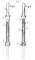
- the prosthesis according to FIGS. 1 and 2consists of the spacer 1, which expediently forms wide support plates 2 and contains a longitudinal bore 3, which is open at one end.
- the other endcarries, firmly connected to the spacer 1, a nail end 4.
- the bore 3contains the other nail 5, which is shown in FIG. 2 in the starting position with continuous lines within the spacer 1 and with dash-dotted lines in the intended final state. Washers 6 are used to adjust the spacer to the required length.
- the spacer 1contains a longitudinal slot 7 through which the screw 8 screwable in the nail 5 projects. By attacking this screw or other means of attack provided on the nail, the nail 5 can be moved in the longitudinal direction and fixed in the desired position.
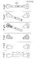
- FIGS. 3 to 6corresponds to that according to FIGS. 1 and 2.
- the spacer 11is divided in the middle and carries on its outer circumference on the one hand right-hand thread 12 and on the other hand left-hand thread 13, the spacer parts being held together by a sleeve 14 provided with a right-hand or left-hand thread and being extendable to any length.
- the required replacement dimension 15is first measured in situ. After the resection (FIG. 8), the bone ends 16, 17 are bent and their medullary canal is opened to receive the nails. According to FIG. 10, the nail 4 firmly connected to the spacer 1 is inserted into the bone end 16. The required length is then established by washers 6 (Fig. 11). The parts are then brought into the extended position and the nail 5 is driven into the bone part 17 by hitting the locking screw 8.
Landscapes
- Health & Medical Sciences (AREA)
- Orthopedic Medicine & Surgery (AREA)
- Cardiology (AREA)
- Oral & Maxillofacial Surgery (AREA)
- Transplantation (AREA)
- Engineering & Computer Science (AREA)
- Biomedical Technology (AREA)
- Heart & Thoracic Surgery (AREA)
- Vascular Medicine (AREA)
- Life Sciences & Earth Sciences (AREA)
- Animal Behavior & Ethology (AREA)
- General Health & Medical Sciences (AREA)
- Public Health (AREA)
- Veterinary Medicine (AREA)
- Prostheses (AREA)
- Surgical Instruments (AREA)
Abstract
Description
Translated fromGermanBei ausgedehnten Knochendefekten, insbesondere bei tumorbedingten Resektionen, besteht die Möglichkeit, durch eine Distanzprothese befallene Gliedmaßen, in weitgehend normaler Funktion zu erhalten bzw. eine sonst manchmal notwendige Amputation zu vermeiden.In the case of extensive bone defects, particularly in the case of tumor-related resections, there is the possibility of maintaining limbs affected by a distance prosthesis in a largely normal function or of avoiding an amputation that is otherwise sometimes necessary.
Zur Befestigung solcher Distanzprothesen, insbesondere im Mittelabschnitt von Röhrenknochen, ist vorzugsweise der Markkanal, proximal und distal, des verbleibenden Knochens geeignet. Dafür muß allerdings nach proximal bzw. distal ein marknagelähnlicher Stift eingebracht werden.The medullary canal, proximal and distal, of the remaining bone is preferably suitable for fastening such distance prostheses, particularly in the central section of long bones. To do this, however, an intramedullary pin must be inserted proximally or distally.
Weichteil-,muskel- und sehnenbedingt ist eine entsprechend weite Extension nicht möglich. Aus diesem Grund werden bereits bekannte Distanzprothesen zweigeteilt verwendet, d.h. der eine Teil wird erst distal eingebracht, der andere Teil proximal und dann in der Mitte zusammengefügt. Bei dieser Form der Distanzprothese ist nachteilig, daß die mittlere Befestigung durch Schrauben etc. in ihrer Stabilität als nicht optimal anzusehen ist. Ein weiterer Nachteil besteht darin, daß diese Prothesen vorher exakt in der notwendigen Größe ausgemessen und vorhanden sein müssen, und kaum die Möglichkeit eines feinjustierbaren Längenausgleiches beinhalten.Soft tissue- muscle and tendon conditions can not be a correspondingly wide extension. For this reason Already known distance prostheses are used in two parts, ie one part is inserted distally, the other part proximally and then joined in the middle. With this form of the distance prosthesis, it is disadvantageous that the stability of the middle fastening by screws etc. is not optimal. Another disadvantage is that these prostheses must first be measured and available in the exact size required and hardly contain the possibility of a finely adjustable length compensation.
Eine weitere Form von bekannten Distanzstücken besteht aus einem Rohr, welches dem Maß der erforderlichen Distanz entsprechen soll. Dieses Rohr wird während der Operation zwischen den verbleibenden Knochenabschnitten, distal und proximal, gehalten, während man vom äußeren proximalen bzw. distalen Ende des betroffenen Gliedmaßes einen Nagel einschlägt, der das rohrförmige Distanzstück auffädelt und damit fixiert. Diese Methode erfordert eine ausgedehntere Operation und erfordert gleichzeitig nachteilig den Zugang zu der Einschlagstelle für den Nagel. Bei bestimmten Gliedmaßen, z.B. Vorderarm bzw. der Tibia (Unterschenkel), ist ein derartiges Vorgehen fast unmöglich. Die Erfindung bezieht sich daher auf eine Endoprothese zum Ersatz des Mittelabschnitts eines langgestreckten Knochens, insbesondere eines Röhrenknochens, die aus einem hülsenförmigen Distanzstück und einem darin längs verschiebbaren Nagel zum Zusammenwirken mit einem Knochenendstück besteht.Another form of known spacers consists of a tube, which should correspond to the measure of the required distance. This tube is held between the remaining bone sections, distal and proximal, during the operation, while a nail is driven in from the outer proximal or distal end of the affected limb, which threads the tubular spacer and thus fixes it. This method requires extensive surgery and at the same time disadvantageously requires access to the point of impact for the nail. With certain limbs, e.g. Forearm or tibia (lower leg), such a procedure is almost impossible. The invention therefore relates to an endoprosthesis for replacing the central section of an elongated bone, in particular a tubular bone, which consists of a sleeve-shaped spacer and a nail which can be displaced longitudinally therein for cooperation with a bone end piece.
Die der Erfindung zugrundeliegende Aufgabe besteht in der Schaffung einer solchen Endoprothese, die operationstechnisch einfacher und mit geringerer Traumatisierung einsetzbar ist.The object on which the invention is based is to provide such an endoprosthesis which is easier to use from an operational point of view and less traumatizing.
Die erfindungsgemäße Lösung besteht darin, daß der Nagel einschließlich seines mit dem Knochenendstück zusammenzuwirken bestimmten Abschnitts in dem Distanzstück aufnehmbar und von der Seite des Distanzstücks her verschiebbar ist.The solution according to the invention is that the nail, including its one, cooperate with the bone end piece certain section can be accommodated in the spacer and displaceable from the side of the spacer.
Zweckmäßigerweise ist ein Knochennagel mit einem Ende des Distanzstücks fest verbunden, während lediglich der für das andere Ende vorgesehene Knochennagel in dem Distanzstück verschiebbar ist. In diesem Fall kann die Prothese durch Abwinkeln der distal bzw. proximal verbleibenden Knochenenden eingebracht werden, indem zunächst der fest mit dem Distanzstück verbundene Knochennagel in ein Ende eingetrieben wird. Danach werden beide verbleibenden Knochenteile in Funktionsstellung ausgerichtet, wobei das Distanzstück der Prothese zwischen den beiden verbleibenden Knochenteilen positioniert ist. Durch Einfügen von Unterlegscheiben läßt sich nun die erforderliche Distanz problemlos herstellen. Danach wird der in dem Distanzstück befindliche zweite Nagel in den anderen Knochenabschnitt eingetrieben.A bone nail is expediently firmly connected to one end of the spacer, while only the bone nail provided for the other end can be displaced in the spacer. In this case, the prosthesis can be inserted by bending the distal or proximal remaining bone ends by first driving the bone nail firmly connected to the spacer into one end. Then both remaining bone parts are aligned in the functional position, the spacer of the prosthesis being positioned between the two remaining bone parts. The required distance can now be easily created by inserting washers. The second nail in the spacer is then driven into the other bone section.
Dafür ist in dem Distanzstück ein Schlitz vorhanden, durch den das zweite Nagelende mit einem geeigneten Instrument eingetrieben werden kann. Nach erfolgtem Eintreiben des zweiten Nagelendes, wird dieses durch eine aus dem Schlitz des Distanzstückes herausragende Befestigungsschraube fixiert. Weil das zweite Nagelende keinerlei Druckbelastung ausgesetzt ist, kommt dieser Fixation eine untergeordnete Bedeutung zu. Neben der Möglichkeit durch Unterlegen von Unterlegscheiben die notwendige Distanzlänge der Prothese während der Operation passend herzustellen, besteht eine weitere vorteilhafte Variante des feindosierbaren Längenausgleichs bei der Prothese durch ein mit links und rechts gewindeversehenes Mittelstück im Bereich des zum Distanzausgleich vorgesehenen Teils der Prothese. Mit diesem Zwischenstück (Muffe) ist eine weitere Distanzdosierbarkeit gegeben und ermöglicht darüber hinaus, falls erforderlich, eine Extension bei bereits geschrumpften Muskelverhältnissen.For this there is a slot in the spacer through which the second nail end can be driven with a suitable instrument. After the second nail end has been driven in, it is fixed by a fastening screw protruding from the slot of the spacer. Because the second nail end is not exposed to any pressure load, this fixation is of minor importance. In addition to the possibility of fitting the necessary distance length of the prosthesis during the operation by placing washers, there is a further advantageous variant of the finely metered length compensation in the prosthesis by means of a middle piece provided with left and right thread in the area of the part of the prosthesis intended for distance compensation. With this intermediate piece (sleeve) a further distance metering is possible and, if necessary, also enables one Extension with already shrunk muscle relationships.
Um das zweite Nagelende durch den Schlitz austreiben zu können, ist die mit Links- und Rechtsgewinde versehene Muffe ebenfalls geschlitzt. Dieser Schlitz muß zum Austreiben des zweiten Nagels mit dem Schlitz des Distanzersatzes in Deckung gebracht werden. Während des Distanzausgleiches mit der Muffe des Distanzstückes werden die beiden in den Knochen eingebrachten Nagelenden des Distanzstückes keinen Rotationskräften unterworfen, so daß die durch das Einschlagen entstandene Verankerung nicht gefährdet wird.In order to be able to drive out the second nail end through the slot, the sleeve provided with left and right-hand threads is also slotted. This slot must be made to coincide with the slot of the spacer replacement in order to drive out the second nail. During the distance compensation with the sleeve of the spacer, the two nail ends of the spacer introduced into the bone are not subjected to any rotational forces, so that the anchoring caused by driving in is not endangered.
Zur zementlosen Verankerung der Nagelenden haben diese vorzugsweise ein im Querschnitt sternförmiges Profil, welches in der Längsrichtung gleichförmig ist. Ebenfalls für die zementierte Verankerung sind die Nagelenden in Längsrichtung profiliert, um eine Rotationsstabilität zu gewährleisten.For cementless anchoring of the nail ends, these preferably have a profile which is star-shaped in cross section and which is uniform in the longitudinal direction. The nail ends are also profiled in the longitudinal direction for the cemented anchoring in order to ensure rotational stability.
Die Erfindung wird im folgenden näher unter Bezugnahme auf die Zeichnungen erläutert. Darin zeigen:
- z Fig. 1 u. 2 eine Seitenansicht und einen Längsschnitt durch eine erste Ausführungsform der Prothese,
- Fig. 3 bis 6 eine zweite Ausführungsform in Seitenansicht, im Längsschnitt im Ausgangszustand bzw. in situ und schließlich im Querschnitt,
- Fig. 7 bis 12 den Operationsvorgang schematisch unter Verwendung einer Prothese gemäß Fig. 1 und 2.
- z Fig. 1 u. 2 shows a side view and a longitudinal section through a first embodiment of the prosthesis,
- 3 to 6 a second embodiment in side view, in longitudinal section in the initial state or in situ and finally in cross section,
- 7 to 12 schematically the operation process using a prosthesis according to FIGS. 1 and 2.
Die Prothese gemäß Fig. 1 und 2 besteht aus dem Distanzstück 1, das zweckmäßigerweise verbreitete Auflageteller 2 bildet und eine Längsbohrung 3 enthält, die an einem Ende offen ist. Das andere Ende trägt, fest mit dem Distanzstück 1 verbunden, ein Nagelende 4. Die Bohrung 3 enthält den anderen Nagel 5, der in Fig. 2 in der Ausgangsstellung mit durchgehenden Linien innerhalb des Distanzstücks 1 und mit strichpunktierten Linien im vorgesehenen Endzustand dargestellt ist. Unterlegscheiben 6 dienen zur Einstellung des Distanzstücks auf die erforderliche Länge. Das Distanzstück 1 enthält einen Längsschlitz 7, durch den die im Nagel 5 verschraubbare Schraube 8 hindurchragt. Durch Angriff an dieser Schraube oder anderen am Nagel vorgesehenen Angriffsmitteln läßt sich der Nagel 5 in Längsrichtung verschieben und in der gewünschten Stellung fixieren.The prosthesis according to FIGS. 1 and 2 consists of the spacer 1, which expediently forms
Die Ausführungsform gemäß Fig. 3 bis 6 stimmt, soweit im folgenden nichts anderes angegeben ist, mit derjenigen gemäß Fig. 1 und 2 überein. Das Distanzstück 11 ist in der Mitte geteilt und trägt an seinem Außenumfang einerseits Rechtsgewinde 12 und andererseits Linkgsgewinde 13, wobei die Distanzstückteile durch eine entsprechend mit Rechts- bzw. Linksgewinde versehene Hülse 14 zusammengehalten und auf eine beliebige Länge extendierbar sind.Unless stated otherwise below, the embodiment according to FIGS. 3 to 6 corresponds to that according to FIGS. 1 and 2. The
In Fig. 7 bis 12 erkennt man, daß zunächst das erforderliche Ersatzmaß 15 in situ gemessen wird. Nach der Resektion (Fig. 8) werden die Knochenenden 16, 17 gebeugt und ihr Markkanal zur Aufnahme der Nägel geöffnet. Gemäß Fig. 10 wird in das Knochenende 16 der fest mit dem Distanzstück 1 verbundene Nagel 4 eingeschoben. Die erforderliche Länge wird dann durch Unterlegscheiben 6 eingerichtet (Fig. 11). Danach werden die Teile in Streckstellung gebracht und wird der Nagel 5 durch Schlagen auf die Feststellschraube 8 in den Knochenteil 17 eingetrieben.7 to 12 it can be seen that the required replacement dimension 15 is first measured in situ. After the resection (FIG. 8), the bone ends 16, 17 are bent and their medullary canal is opened to receive the nails. According to FIG. 10, the nail 4 firmly connected to the spacer 1 is inserted into the bone end 16. The required length is then established by washers 6 (Fig. 11). The parts are then brought into the extended position and the
Claims (2)
Translated fromGermanApplications Claiming Priority (2)
| Application Number | Priority Date | Filing Date | Title |
|---|---|---|---|
| DE3528728 | 1985-08-09 | ||
| DE19853528728DE3528728A1 (en) | 1985-08-09 | 1985-08-09 | ENDOPROTHESIS TO REPLACE THE MEDIUM SECTION OF A LONG-STRETCHED BONE |
Publications (2)
| Publication Number | Publication Date |
|---|---|
| EP0212192A1true EP0212192A1 (en) | 1987-03-04 |
| EP0212192B1 EP0212192B1 (en) | 1989-12-13 |
Family
ID=6278197
Family Applications (1)
| Application Number | Title | Priority Date | Filing Date |
|---|---|---|---|
| EP86109228AExpiredEP0212192B1 (en) | 1985-08-09 | 1986-07-07 | Endoprosthesis for the replacement of the middle portion of a long bone |
Country Status (2)
| Country | Link |
|---|---|
| EP (1) | EP0212192B1 (en) |
| DE (2) | DE3528728A1 (en) |
Cited By (13)
| Publication number | Priority date | Publication date | Assignee | Title |
|---|---|---|---|---|
| EP0346247A1 (en)* | 1988-06-09 | 1989-12-13 | Medinov Sarl | Progressively lengthening intramedullar nail |
| DE8911046U1 (en)* | 1988-09-14 | 1990-02-08 | Pfizer Hospital Products Group, Inc., New York, N.Y. | Modular prosthesis |
| DE3909182C1 (en)* | 1989-03-21 | 1990-08-09 | Orthoplant Endoprothetik Gmbh, 2800 Bremen, De | |
| DE3935488A1 (en)* | 1989-10-25 | 1991-05-02 | Orthoplant Endoprothetik | Knee joint endoprosthesis - incorporates shaft of adjustable length to accommodate growth of patient |
| US5032130A (en)* | 1989-03-21 | 1991-07-16 | Bristol-Myers Squibb Company | Hip prosthesis |
| US5358524A (en)* | 1993-02-16 | 1994-10-25 | Wright Medical Technology, Inc. | Adjustable length prosthetic implant |
| US5387239A (en)* | 1993-04-19 | 1995-02-07 | Wright Medical Technology, Inc. | Adjustable length prosthetic implant |
| FR2737107A1 (en)* | 1995-07-26 | 1997-01-31 | Medinov Sa | Assembly connection for two parts of joint prosthesis component - has connecting screw with enlarged head secured in female component by threaded locking washer and threaded shaft securing male component |
| EP1088530A1 (en)* | 1999-09-24 | 2001-04-04 | Waldemar Link (GmbH & Co.) | Alloplastic prosthesis for long bone |
| EP1470799A3 (en)* | 2003-03-31 | 2006-01-18 | Depuy Products, Inc. | Intercalary implant |
| US7125423B2 (en) | 2003-03-31 | 2006-10-24 | Depuy Products, Inc. | Intercalary prosthesis, kit and method |
| US7198642B2 (en) | 2003-03-31 | 2007-04-03 | Depuy Products, Inc. | Orthopaedic spacer |
| CN109938881A (en)* | 2017-12-20 | 2019-06-28 | 山东威高骨科材料股份有限公司 | The installing mechanism and its production assembly method of artificial bone |
Families Citing this family (4)
| Publication number | Priority date | Publication date | Assignee | Title |
|---|---|---|---|---|
| US5211664A (en)* | 1992-01-14 | 1993-05-18 | Forschungsinstitut, Davos Laboratorium Fur Experimentelle Chirugie | Shell structure for bone replacement |
| DE19633865A1 (en)* | 1996-08-16 | 1998-02-19 | Guenter Prof Dr Med Lob | Endoprosthesis |
| US10238436B2 (en) | 2014-05-16 | 2019-03-26 | University Of Kentucky Research Foundation | Temporary fracture stabilization device |
| EP3932369B1 (en)* | 2020-06-03 | 2025-06-04 | Howmedica Osteonics Corp. | Intercalary endoprosthesis |
Citations (6)
| Publication number | Priority date | Publication date | Assignee | Title |
|---|---|---|---|---|
| DE2049111A1 (en)* | 1969-10-06 | 1971-04-08 | ||
| DE3205577A1 (en)* | 1981-02-23 | 1982-10-28 | Howmedica International, Inc. Zweigniederlassung Kiel, 2300 Kiel | BONE PROSTHESIS |
| DE3138848A1 (en)* | 1981-09-30 | 1983-04-21 | GMT GESELLSCHAFT FüR MEDIZINISCHE TECHNIK MBH | ENDOPROTHESIS TO REPLACE ROD-SHAPED BONES |
| GB2137098A (en)* | 1983-03-22 | 1984-10-03 | Nat Res Dev | Endoprosthetic Bone Joint Devices |
| GB2137884A (en)* | 1983-04-12 | 1984-10-17 | Nat Res Dev | Endoprosthetic bone devices |
| US4502160A (en)* | 1983-10-27 | 1985-03-05 | Dow Corning Wright | Adjustable length prosthetic joint implant |
- 1985
- 1985-08-09DEDE19853528728patent/DE3528728A1/ennot_activeWithdrawn
- 1986
- 1986-07-07DEDE8686109228Tpatent/DE3667393D1/ennot_activeExpired - Fee Related
- 1986-07-07EPEP86109228Apatent/EP0212192B1/ennot_activeExpired
Patent Citations (6)
| Publication number | Priority date | Publication date | Assignee | Title |
|---|---|---|---|---|
| DE2049111A1 (en)* | 1969-10-06 | 1971-04-08 | ||
| DE3205577A1 (en)* | 1981-02-23 | 1982-10-28 | Howmedica International, Inc. Zweigniederlassung Kiel, 2300 Kiel | BONE PROSTHESIS |
| DE3138848A1 (en)* | 1981-09-30 | 1983-04-21 | GMT GESELLSCHAFT FüR MEDIZINISCHE TECHNIK MBH | ENDOPROTHESIS TO REPLACE ROD-SHAPED BONES |
| GB2137098A (en)* | 1983-03-22 | 1984-10-03 | Nat Res Dev | Endoprosthetic Bone Joint Devices |
| GB2137884A (en)* | 1983-04-12 | 1984-10-17 | Nat Res Dev | Endoprosthetic bone devices |
| US4502160A (en)* | 1983-10-27 | 1985-03-05 | Dow Corning Wright | Adjustable length prosthetic joint implant |
Cited By (18)
| Publication number | Priority date | Publication date | Assignee | Title |
|---|---|---|---|---|
| EP0346247A1 (en)* | 1988-06-09 | 1989-12-13 | Medinov Sarl | Progressively lengthening intramedullar nail |
| FR2632514A1 (en)* | 1988-06-09 | 1989-12-15 | Medinov Sarl | PROGRESSIVE CENTRO-MEDULLAILE NAIL |
| DE8911046U1 (en)* | 1988-09-14 | 1990-02-08 | Pfizer Hospital Products Group, Inc., New York, N.Y. | Modular prosthesis |
| US5108437A (en)* | 1988-09-14 | 1992-04-28 | Pfizer Hospital Products Group, Inc. | Modular prosthesis |
| DE3909182C1 (en)* | 1989-03-21 | 1990-08-09 | Orthoplant Endoprothetik Gmbh, 2800 Bremen, De | |
| US5032130A (en)* | 1989-03-21 | 1991-07-16 | Bristol-Myers Squibb Company | Hip prosthesis |
| DE3935488A1 (en)* | 1989-10-25 | 1991-05-02 | Orthoplant Endoprothetik | Knee joint endoprosthesis - incorporates shaft of adjustable length to accommodate growth of patient |
| US5358524A (en)* | 1993-02-16 | 1994-10-25 | Wright Medical Technology, Inc. | Adjustable length prosthetic implant |
| US5387239A (en)* | 1993-04-19 | 1995-02-07 | Wright Medical Technology, Inc. | Adjustable length prosthetic implant |
| FR2737107A1 (en)* | 1995-07-26 | 1997-01-31 | Medinov Sa | Assembly connection for two parts of joint prosthesis component - has connecting screw with enlarged head secured in female component by threaded locking washer and threaded shaft securing male component |
| EP1088530A1 (en)* | 1999-09-24 | 2001-04-04 | Waldemar Link (GmbH & Co.) | Alloplastic prosthesis for long bone |
| US6569203B1 (en) | 1999-09-24 | 2003-05-27 | Waldemar Link (Gmbh & Co.) | Alloplastic replacement for a long bone |
| EP1470799A3 (en)* | 2003-03-31 | 2006-01-18 | Depuy Products, Inc. | Intercalary implant |
| US7125423B2 (en) | 2003-03-31 | 2006-10-24 | Depuy Products, Inc. | Intercalary prosthesis, kit and method |
| US7141067B2 (en) | 2003-03-31 | 2006-11-28 | Depuy Products, Inc. | Intercalary implant |
| US7198642B2 (en) | 2003-03-31 | 2007-04-03 | Depuy Products, Inc. | Orthopaedic spacer |
| CN109938881A (en)* | 2017-12-20 | 2019-06-28 | 山东威高骨科材料股份有限公司 | The installing mechanism and its production assembly method of artificial bone |
| CN109938881B (en)* | 2017-12-20 | 2023-08-01 | 山东威高骨科材料股份有限公司 | Artificial bone mounting mechanism |
Also Published As
| Publication number | Publication date |
|---|---|
| DE3528728A1 (en) | 1987-02-12 |
| DE3667393D1 (en) | 1990-01-18 |
| EP0212192B1 (en) | 1989-12-13 |
Similar Documents
| Publication | Publication Date | Title |
|---|---|---|
| EP0212192B1 (en) | Endoprosthesis for the replacement of the middle portion of a long bone | |
| DE68924114T2 (en) | Guide instrument for piercing the bone cortex, suitable for locating the holes of intramedullary nails. | |
| DE69521798T2 (en) | DEVICE FOR CORRECTING LONG BONE BENDING | |
| DE3751339T2 (en) | Components of a modular system for fixing the femur. | |
| DE69519169T2 (en) | MECHANICAL DEVICE FOR ALIGNING BONE SCREWS TO BE INSERTED IN A MARKEL | |
| EP0613663B1 (en) | Modular intramedullary nail | |
| DE69720177T2 (en) | Medullary nail for the treatment of hip fractures | |
| EP0491138B1 (en) | Device for holding broken bones in fixed position | |
| DE69916294T2 (en) | DEVICE FOR POSTERIORS SPINE-COLUMN OSTEOSYNTHESIS | |
| DE69400299T2 (en) | Device for holding the spine | |
| DE60014042T2 (en) | Axial external fixator | |
| DE69510516T2 (en) | Osteosynthetic device for attachment and / or longitudinal alignment | |
| DE69822197T2 (en) | DRILLING TO INSTALL A BOLT ON THE RAIL | |
| DE69934999T2 (en) | TREATMENT OF BONE FRACTURES | |
| DE69514257T2 (en) | Implant for the treatment of fractures of the femur | |
| DE19619093B4 (en) | Intramedullary nail system for fracture healing or bone extension | |
| DE68915736T2 (en) | Device for implanting prostheses. | |
| DE2601938A1 (en) | GUIDE RAIL FOR A DISTRACTION DEVICE | |
| DE4414177A1 (en) | Double nail guide system for targeting distal screw holes of locking nails | |
| DE602005003462T2 (en) | ASSEMBLY ARRANGEMENT FOR IMPLANTING KNEE PROSTHESES | |
| EP0371910A1 (en) | Intramedullary nail | |
| DE69918068T2 (en) | CABLE SHEAR ARRANGEMENT FOR BONE FIXATION | |
| DE2246274A1 (en) | DEVICE FOR TREATMENT OF BROKEN TUBE BONES BY AXIAL PRESSURE OSTEOSYNTHESIS | |
| AT509852A4 (en) | FLEXIBLE HUMERUS NAIL | |
| DE68902674T2 (en) | Hip joint prosthesis. |
Legal Events
| Date | Code | Title | Description |
|---|---|---|---|
| PUAI | Public reference made under article 153(3) epc to a published international application that has entered the european phase | Free format text:ORIGINAL CODE: 0009012 | |
| AK | Designated contracting states | Kind code of ref document:A1 Designated state(s):DE FR GB IT SE | |
| 17P | Request for examination filed | Effective date:19870817 | |
| 17Q | First examination report despatched | Effective date:19890427 | |
| GRAA | (expected) grant | Free format text:ORIGINAL CODE: 0009210 | |
| AK | Designated contracting states | Kind code of ref document:B1 Designated state(s):DE FR GB IT SE | |
| REF | Corresponds to: | Ref document number:3667393 Country of ref document:DE Date of ref document:19900118 | |
| ITF | It: translation for a ep patent filed | ||
| ET | Fr: translation filed | ||
| GBT | Gb: translation of ep patent filed (gb section 77(6)(a)/1977) | ||
| PLBE | No opposition filed within time limit | Free format text:ORIGINAL CODE: 0009261 | |
| STAA | Information on the status of an ep patent application or granted ep patent | Free format text:STATUS: NO OPPOSITION FILED WITHIN TIME LIMIT | |
| 26N | No opposition filed | ||
| ITTA | It: last paid annual fee | ||
| EAL | Se: european patent in force in sweden | Ref document number:86109228.6 | |
| REG | Reference to a national code | Ref country code:GB Ref legal event code:IF02 | |
| PGFP | Annual fee paid to national office [announced via postgrant information from national office to epo] | Ref country code:GB Payment date:20030613 Year of fee payment:18 | |
| PGFP | Annual fee paid to national office [announced via postgrant information from national office to epo] | Ref country code:FR Payment date:20030721 Year of fee payment:18 | |
| PGFP | Annual fee paid to national office [announced via postgrant information from national office to epo] | Ref country code:SE Payment date:20030728 Year of fee payment:18 | |
| PGFP | Annual fee paid to national office [announced via postgrant information from national office to epo] | Ref country code:DE Payment date:20030923 Year of fee payment:18 | |
| PG25 | Lapsed in a contracting state [announced via postgrant information from national office to epo] | Ref country code:GB Free format text:LAPSE BECAUSE OF NON-PAYMENT OF DUE FEES Effective date:20040707 | |
| PG25 | Lapsed in a contracting state [announced via postgrant information from national office to epo] | Ref country code:SE Free format text:LAPSE BECAUSE OF NON-PAYMENT OF DUE FEES Effective date:20040708 | |
| PG25 | Lapsed in a contracting state [announced via postgrant information from national office to epo] | Ref country code:DE Free format text:LAPSE BECAUSE OF NON-PAYMENT OF DUE FEES Effective date:20050201 | |
| EUG | Se: european patent has lapsed | ||
| GBPC | Gb: european patent ceased through non-payment of renewal fee | Effective date:20040707 | |
| PG25 | Lapsed in a contracting state [announced via postgrant information from national office to epo] | Ref country code:FR Free format text:LAPSE BECAUSE OF NON-PAYMENT OF DUE FEES Effective date:20050331 | |
| REG | Reference to a national code | Ref country code:FR Ref legal event code:ST | |
| PG25 | Lapsed in a contracting state [announced via postgrant information from national office to epo] | Ref country code:IT Free format text:LAPSE BECAUSE OF NON-PAYMENT OF DUE FEES;WARNING: LAPSES OF ITALIAN PATENTS WITH EFFECTIVE DATE BEFORE 2007 MAY HAVE OCCURRED AT ANY TIME BEFORE 2007. THE CORRECT EFFECTIVE DATE MAY BE DIFFERENT FROM THE ONE RECORDED. Effective date:20050707 |