EP0209215A1 - Ferromagnetic element with temperature regulation - Google Patents
Ferromagnetic element with temperature regulationDownload PDFInfo
- Publication number
- EP0209215A1 EP0209215A1EP86303261AEP86303261AEP0209215A1EP 0209215 A1EP0209215 A1EP 0209215A1EP 86303261 AEP86303261 AEP 86303261AEP 86303261 AEP86303261 AEP 86303261AEP 0209215 A1EP0209215 A1EP 0209215A1
- Authority
- EP
- European Patent Office
- Prior art keywords
- temperature
- current
- curie
- sensing
- permeability
- Prior art date
- Legal status (The legal status is an assumption and is not a legal conclusion. Google has not performed a legal analysis and makes no representation as to the accuracy of the status listed.)
- Granted
Links
- 230000005294ferromagnetic effectEffects0.000titleclaimsabstractdescription44
- 230000033228biological regulationEffects0.000titleclaimsdescription11
- 230000007704transitionEffects0.000claimsabstractdescription45
- 230000035699permeabilityEffects0.000claimsabstractdescription39
- 230000008859changeEffects0.000claimsabstractdescription29
- 238000000034methodMethods0.000claimsabstractdescription22
- 230000006698inductionEffects0.000claimsabstractdescription7
- 238000010438heat treatmentMethods0.000claimsabstractdescription5
- 230000004044responseEffects0.000claimsdescription13
- 230000007423decreaseEffects0.000claimsdescription10
- 230000001965increasing effectEffects0.000claimsdescription7
- 239000003302ferromagnetic materialSubstances0.000claimsdescription5
- 230000003247decreasing effectEffects0.000claimsdescription3
- 230000001105regulatory effectEffects0.000claims18
- 230000005291magnetic effectEffects0.000claims8
- 230000004907fluxEffects0.000claims6
- 230000001939inductive effectEffects0.000claims4
- 230000005415magnetizationEffects0.000claims2
- 230000002035prolonged effectEffects0.000claims2
- 239000000463materialSubstances0.000claims1
- 230000009467reductionEffects0.000claims1
- 238000001816coolingMethods0.000abstractdescription10
- 230000008569processEffects0.000abstractdescription4
- 238000004804windingMethods0.000abstractdescription2
- 230000000630rising effectEffects0.000abstract1
- XEEYBQQBJWHFJM-UHFFFAOYSA-NIronChemical compound[Fe]XEEYBQQBJWHFJM-UHFFFAOYSA-N0.000description6
- 238000010586diagramMethods0.000description5
- 239000007787solidSubstances0.000description4
- 229910052742ironInorganic materials0.000description3
- 238000005476solderingMethods0.000description3
- CURLTUGMZLYLDI-UHFFFAOYSA-NCarbon dioxideChemical compoundO=C=OCURLTUGMZLYLDI-UHFFFAOYSA-N0.000description2
- RYGMFSIKBFXOCR-UHFFFAOYSA-NCopperChemical compound[Cu]RYGMFSIKBFXOCR-UHFFFAOYSA-N0.000description2
- PXHVJJICTQNCMI-UHFFFAOYSA-NNickelChemical compound[Ni]PXHVJJICTQNCMI-UHFFFAOYSA-N0.000description2
- 230000008901benefitEffects0.000description2
- 239000003990capacitorSubstances0.000description2
- 229910052802copperInorganic materials0.000description2
- 239000010949copperSubstances0.000description2
- 230000002500effect on skinEffects0.000description2
- 238000000605extractionMethods0.000description2
- 229910001374InvarInorganic materials0.000description1
- 229910001030Iron–nickel alloyInorganic materials0.000description1
- 229910045601alloyInorganic materials0.000description1
- 239000000956alloySubstances0.000description1
- 229910002092carbon dioxideInorganic materials0.000description1
- 239000001569carbon dioxideSubstances0.000description1
- 238000006243chemical reactionMethods0.000description1
- 239000002131composite materialSubstances0.000description1
- 239000004020conductorSubstances0.000description1
- 239000012809cooling fluidSubstances0.000description1
- 230000000875corresponding effectEffects0.000description1
- 230000006872improvementEffects0.000description1
- 239000000203mixtureSubstances0.000description1
- 229910052759nickelInorganic materials0.000description1
- 239000000126substanceSubstances0.000description1
- 239000000758substrateSubstances0.000description1
- 239000002344surface layerSubstances0.000description1
- 229910002058ternary alloyInorganic materials0.000description1
- 230000001960triggered effectEffects0.000description1
Images


Classifications
- G—PHYSICS
- G05—CONTROLLING; REGULATING
- G05D—SYSTEMS FOR CONTROLLING OR REGULATING NON-ELECTRIC VARIABLES
- G05D23/00—Control of temperature
- G05D23/19—Control of temperature characterised by the use of electric means
- G05D23/20—Control of temperature characterised by the use of electric means with sensing elements having variation of electric or magnetic properties with change of temperature
- G05D23/26—Control of temperature characterised by the use of electric means with sensing elements having variation of electric or magnetic properties with change of temperature the sensing element having a permeability varying with temperature
- H—ELECTRICITY
- H05—ELECTRIC TECHNIQUES NOT OTHERWISE PROVIDED FOR
- H05B—ELECTRIC HEATING; ELECTRIC LIGHT SOURCES NOT OTHERWISE PROVIDED FOR; CIRCUIT ARRANGEMENTS FOR ELECTRIC LIGHT SOURCES, IN GENERAL
- H05B3/00—Ohmic-resistance heating
- H05B3/0019—Circuit arrangements
- H05B3/0023—Circuit arrangements for heating by passing the current directly across the material to be heated
- H—ELECTRICITY
- H05—ELECTRIC TECHNIQUES NOT OTHERWISE PROVIDED FOR
- H05B—ELECTRIC HEATING; ELECTRIC LIGHT SOURCES NOT OTHERWISE PROVIDED FOR; CIRCUIT ARRANGEMENTS FOR ELECTRIC LIGHT SOURCES, IN GENERAL
- H05B6/00—Heating by electric, magnetic or electromagnetic fields
- H05B6/02—Induction heating
- H05B6/06—Control, e.g. of temperature, of power
- H—ELECTRICITY
- H05—ELECTRIC TECHNIQUES NOT OTHERWISE PROVIDED FOR
- H05B—ELECTRIC HEATING; ELECTRIC LIGHT SOURCES NOT OTHERWISE PROVIDED FOR; CIRCUIT ARRANGEMENTS FOR ELECTRIC LIGHT SOURCES, IN GENERAL
- H05B2213/00—Aspects relating both to resistive heating and to induction heating, covered by H05B3/00 and H05B6/00
- H05B2213/07—Heating plates with temperature control means
Definitions
- This inventionrelates to ferromagnetic elements possessing temperature regulation when electrically heated.
- the Carter-Krumme patent in col. 7states the effectiveness of the device in terms of where R max is the resistan of the device below Curie and R min is the resistance of the device above Curie.
- the Carter-Krumme patentteaches that the preferred frequency range is 8 to 20MHz.
- a pure ferromagnetic elementis preferably used; although a composite element such as that taught by the Carter-Krumme patent could be used.
- Radio frequency currentpreferably in the general range of 5 to 20MHz is passed through the ferromagnetic element, either directly or by induction.
- the amplitude of the currentis selected so as to heat the element well above its effective Curie.
- An advantage of this invention over the prior artis that it may employ a much larger current than was feasible with the prior art.
- the currentwill quickly increase the temperature of the element to its effective Curie.
- the permeability of the ferromagnetic elementwill drop sharply. This sharp drop is sensed, and, when sensed the current to the element is cut-off. The element then cools below the effective Curie and the current is restored so as to again heat the element, to its effective Curie.
- the processthen repeats itself, hence a pulsating large current is fed to the element in such a manner as to hold its temperature fairly constant.
- the sharp drop in permeabilitymay, according to this invention be sensed in several different ways.
- One such wayis to have the winding of an auto-transformer around the ferromagnetic element.
- Another wayis to sense the change in power drawn by the ferromagnetic element, since the device may be so designed that the power will decline when the permeability declines. When the power sharply declines the current is cut-off for a brief period and is then restored.
- Figure 1illustrates a prior art ferromagnetic strip B which may be 0.010 inches thick and 0.2 inches wide, composed of nickel-iron alloy having a permeability of over 100 and an effective Curie temperature in the range of 150°C or more.
- the constant current power supply PSis capable of delivering sufficient power to the strip to heat it well above the effective Curie temperature, for example 70°C above the effective Curie. If then the current is turned on, the strip B will be heated to temperature T (Fig. 4) which is say 70°C above the effective Curie C. If now a source of cooling fluid, for example gaseous carbon dioxide is passed over strip B in progressively increasing quantity the temperature will fall along line E to level C and will remain there until ultimately the cooling is so great that the temperature will fall off along tail line D.
- a source of cooling fluidfor example gaseous carbon dioxide
- FIG. 2illustrates a similar prior art arrangement in which current is induced in ferromagnetic strip B by induction. This device will function in the same way as the device of Figure 1.
- the present inventionavoids the portion E of the curve above the effective Curie temperature and also either avoids tail line D or at least postpones it to such a high cooling rate that it is no problem.
- a ferromagneic strip or bar 10has a diameter or thickness of at least several thousandths of an inch.
- the configuration of element 10may vary depending on the desired end use. For example, if the end use is a soldering iron, element 10 may have the shape of a soldering iron.
- a small pick-up coil 11is adjacent to, or around, a part, of ferromagnetic strip, bar or rod 10.
- Coil 11will function as an auto-transformer.
- the left half of the coil 11is the primary and the right half of the coil 11 is the secondary.
- a 60Hz alternating current source 19such as the secondary of a small transformer fed by a 60Hz power line.
- the voltage of source 19may be in the range of 8 to 24 volts.
- the control relay 16, 17will be energized by the voltage or current induced in the secondary of auto-transformer 11 and will close the circuit to ferromagnetic member 10 when the ferromagnetic member 10 is below Curie.
- the ferromagnetic member 10has high permeability and current will be induced in the secondary of auto-transformer 11.
- the secondary of auto-transformer 11applies an a.c. voltage across wires 12 and 14. This voltage is rectified by rectifier 15 and feeds relay coil 16, attracting armature 17 to close a circuit from source 18 through ferromagnetic member 10.
- the sourcemay be in the range of 5 to 20 MHz, for example, and feeds sufficient RF current through member 10 to heat it well above Curie. As the member 10 is heated near or above Curie the auto-transformer 11 is no longer effective since the permeability of member 10 has dropped toward unity, hence the voltage in the secondary of the auto-transformer falls.
- the relay coil 16is deenergized and armature 17 opens the circuit under the pull of spring 20.
- the current to the ferromagnetic member 10 from R.F. source 18is cut-off.
- the ferromagnetic member 10then cools and when its temperature falls below Curie the auto-transformer 11 again becomes operative due to the high permeability of member 10.
- the secondary of auto-transformer 11now puts out full voltage, the relay 16, 17 closes and current from source 18 is again passed through member 10 to heat it above Curie. The cycle then repeats over and over.
- Solid state controlsmay replace parts 15, 16, 17.
- the member 10may be of high permeability such as Invar, Alloy 42, or a ternary alloy composed of 45% nickel, 46% iron and 9% molybdium.
- the parameters such as the amplitude of the current from source 18, time delay etc. of relay 16, 17may be selected so that the relay 16, 17 opens and closes rapidly (several times a second).
- the time delay of the partswill be selected to get the proper frequency for the opening and closing of the solid state switch corresponding to relay 16, 17. If then there is a high rate of extraction of heat from member 10 the relay 16, 17 will be closed longer than it is open etc. But if one section 21 of the member 10 has much more heat extracted therefrom than is extracted from other equally wide sections, the section 21 will receive more heat from the current as will be explained. In such case, the section 21 will remain far below Curie and will not rise above when the relay armature 17 is closed.
- section 21will have higher resistance per unit of length than the rest of member 10. Since the same current traverses the entire length of member 10, section 21 will get more heat per unit length, and thus provide more heat to offset the fact that there is greater extraction of heat from section 21.
- R.F. source 18may be a constant current source but this is not necessary. The fact that it is disconnected from the load above Curie is sufficient control over the current.
- a key pointis that means are employed to detect the transition from below to above Curie and in response to detecting that transition the current thru the ferromagnetic bar is cut off. If the device is arranged to cycle on and off; and if the "off" periods are kept of short, the device should hold its temperature quite constant.
- relay 16, 17it is preferable for the relay 16, 17 to completely disconnect the source 18 from the ferromagnetic strip 10.
- Figures 5 and 6illustrate a different way of sensing the Curie transition.
- the change in powerthat occurs when the temperature increases through the Curie transition is sensed, and in response to sensing that change in power, the current to the ferromagnetic element is either cut-off or reduced.
- the load 69is the high permeability ferromagnetic element and may have the composition, shape, and size described above, or as desired for any given end use.
- FIG. 5illustrates a constant voltage power supply for use with the invention.
- This power supplyhas conventional oscillator 50, conventional buffer 51, conventional driver 52, and conventional class C amplifier 53, stages. While a wide variety of such equipment is available, one suitable form is shown in The ARRL 1985 Handbook (62nd Ed., 1985), published by the American Radio Relay League, Chapter 30, pages 30-24 to 30-26. A copy of the applicable pages of this handbook is being filed with this application.
- the driver 52has an input 67 to key the same on and off and this corresponds to the key jack J1 on page 30-24 of said handbook.
- the driver 52is keyed on contacts of a small fast electromagnetic relay (not shown) in a conventional fashion; the relay coil being energized by input 67.
- the linear power amplifier 54may be any, of many, suitable linear power amplifiers, for example it may be the 140 Watt Solid State Linear Amplifier, shown on pages 30-27 to 30-30 of said ARRL 1985 Handbook. See also the Motorola RF Data Manual (3rd. Ed., 1983), pages 4-194 to 4-199.
- the output of linear power amplifier 54is fed through resistor 61, which feeds impedance matching transformer 68 which in turn feeds the load 69.
- the voltage at the output of the linear power amplifier 54is held constant by the components 55-60 as follows.
- Resistors 55 and 56form a voltage divider across the output of power amplifier 54.
- the diode 57feeds resistor 58 and capacitor 81, and amplifier 59, so that the output of the latter reflects the voltage at the output of power amplifier 54.
- That outputfeeds power regulator 60 which may be Texas Instruments Inc. Type LM 117, described on pages 99 to 103 of The Voltage Regulator Handbook published by Texas Instruments, Inc. A copy of the applicable pages of this handbook are being filed with this application.
- This regulator 60controls the main power input circuit 70 to the Class C amplifier 53 to thus raise or lower the output voltage thereof as necessary to keep the output voltage of linear amplifier 54 fairly constant.
- This regulator 60has a built-in conventional standard voltage reference source which is compared with the voltage at the output of amplifier 59, and the regulator 60 then functions to hold the voltage at the output of linear amplifier 54 constant.
- Timer 66has a built in standard reference voltage which is compared with the voltage at the output of amplifier 64, and the timer is triggered to start its time period when the voltage at the output of amplifier 64 increases above the standard reference voltage. When this happens the timer 66 opens the keying circuit 67 to cut-off all power at the output of linear amplifier 54.
- Figure 6illustrates a constant current power supply suitable for use with the invention.
- the power generating stages 50 to 54 in Figure 6are essentially the same as for Figure 5, although they are controlled in a different way; and therefore it is unnecessary to further describe those stages.
- the current from the output of power amplifier 54 to the load 69is held constant by components 60, 62, 63 and 64 as follows.
- the current through resistor 61increases the voltage drop across that resistor 61 is fed to the input of operational amplifier 64 whose output controls power regulator 60 (which may be Texas Instruments, Inc. Type LM 117 described above).
- the power regulator 60controls the voltage fed to Class C amplifier 53 to thus hold the output current of power amplifier 54 constant.
- the regulator 60has built-in standard reference voltage which is compared with the voltage at the output of amplifier 64, and the regulator 60 functions to keep the two voltages the same and thus keep the current at load 69 constant.
- the timer 66has a built-in standard reference voltage which is compared with the voltage at the output of amplifier 59. When the voltage, at the output of amplifier 5° drops below the reference voltage, the timer 66 cuts-off driver 52 for a predetermined time interval as explained in connection with Figure 5.
- the operational amplifiers 59 and 64 of both Figure 5 and 6may be Type uA741M or uA741C, manufactured by Texas Instruments, Inc., and a data sheet describing these amplifiers is being filed with this application.
- the timer 66 of both Figures 5 and 6may be Type 555 manufactured by Texas Instruments, Inc., and the manufacturer's data sheet for this timer 66 is being filed with this application. When this form of timer is used the input signal is fed into the Trigger (pin 2) of the timer 66.
- the impedance matching transformer 68 in both Figures 5 and 6may be designed and/or selected according to conventional practices such as those described in said Motorola RF Device Data manual pages 4-145 to 4-153, or said ARRL 1985 Handbook, Figure 44, page 30-28.
- the resistance values of the various resistorsmay be as follows; it being understood of course that changes are necessary for different designs:
- Capacitors 75, 80 and 81may have a capacity of 0.001 mfd.
- the current fed to the load 10 or 69is not limited by the permissible temperature T (Fig. 3).
- the current that may be applied to the load 10 or 69may be much higher than is permissible with Figures 1 and 2 or with any other known prior art. If a very large cooling load is applied to ferromagnetic elements 10 or 69, the heavy current to those elements will be on a much larger percentage of the time than will be the case for a small cooling load. For example, if the cooling load is light, the heavy current will quickly reheat the ferromagnetic load element 10 or 69, after the current is restored by the closing of relay 16, 17 or by the expiration of the time interval of timer 66. But if the cooling load is very heavy the time period for heating the ferromagnetic load element after the current is turned on will be longer than was the case for the light load.
- the curvewould consist of a single horizontal substantially straight line at the effective Curie temperature G.
- Another advantage of the invention over the prior art referred to above,is that it will work over a very wide band of frequencies.
- the device of Figure 4will work, even if power supply 18 has an output frequency as low as 60 Hz or even lower. In such a case the invention would lose the value of providing greater heat to a limited section 21 (Fig. 4), that is cooled more than other sections, if the strip or bar 10 or 69, is of small size.
- the feature of providing increased heating to a limited section such as 21,is applicable to all forms of the invention ( Figures 4, 5 and 6), if the frequency is high enough to provide the necessary change in skin depth.
- the frequency and the size of the ferromagnetic elementshould be so related that there is a substantial change in skin depth, due to the change in permeability, as the temperature goes through the Curie transition if a section such as 21 is to get added heat when it is cooled.
- a strip several thousandths of an inch thickwill meet this requirement in the 8-20 MHz range.
- the ferromagnetic loadmay be several skin depths thick, for example, to meet this requirement.
- the change in skin depth during the Curie transitionwill result in a change in resistance of the load 69, which will result in a change in power, which is sensed and used as a control parameter.
- the inventionhas end uses wherever it is desired to hold the temperature of a strip, rod, bar, or other configuration constant.
- One such use for exampleis in soldering as it is often undesirable to overheat apparatus being soldered.
- the ferromagnetic element 10 or 69may be all or part of an element being soldered, or it may be located in contact with an element being soldered.
- the ferromagnetic elements 10 or 69may also be used as heaters to heat chemicals to make sure that chemical reactions occur at predetermined constant temperatures.
Landscapes
- Physics & Mathematics (AREA)
- General Physics & Mathematics (AREA)
- Engineering & Computer Science (AREA)
- Automation & Control Theory (AREA)
- Electromagnetism (AREA)
- General Induction Heating (AREA)
- Control Of Resistance Heating (AREA)
- Resistance Heating (AREA)
- Hard Magnetic Materials (AREA)
- Transformers For Measuring Instruments (AREA)
Abstract
Description
- This invention relates to ferromagnetic elements possessing temperature regulation when electrically heated.
- It is old and well known to regulate the temperature of a ferromagnetic element by passing a radio frequency current through it. The current heats the element to its effective Curie temperature where, due to a change in permeability of the element, the power drawn by the element declines, and therefore the device will hold its temperature constant. The "effective" Curie is the temperature at which the device regulates its temperature and is 50-100°C below the actual published Curie temperature. Hereafter, when we refer to Curie it should be understood that we are referring to the effective Curie, unless otherwise stated. The current may be fed through the ferromagnetic element directly, as by electrical conductors connected between the element and a source of current, or by induction. However, the known prior art employing a pure ferromagnetic element has the drawback that it will not hold the temperature constant over a wide range of cooling loads.
- An improvement in the aforesaid temperature regulation method is known and described in U.S. Patent 4,256,945, issued March 17, 1981, to Philip S. Carter and John F. Krumme, entitled Alternating Current Electrically Resistive Heating Element Having Intrinsic Temperature Control. This patent teaches that the temperature regulation may be improved if the ferromagnetic element surrounds a copper substrate. Below the effective Curie the current is driven into the ferromagnetic surface layer by strong skin effect forces. When the temperature rises above the effective Curie temperature the skin effect is not strong due to the change in permeability of the ferromagnetic material, and at least some of the current retreats into the copper. This results in a sharp drop in power; since the current is held constant throughout the process. Hence, it is possible to design such a device that holds its temperature constant over a wider range of thermal cooling loads than was the case with the ferromagnetic element.
- The Carter-Krumme patent in col. 7 states the effectiveness of the device in terms ofwhereRmax is the resistan of the device below Curie andRmin is the resistance of the device above Curie.

- The Carter-Krumme patent teaches that the preferred frequency range is 8 to 20MHz.
- With the present invention a pure ferromagnetic element is preferably used; although a composite element such as that taught by the Carter-Krumme patent could be used.
- Radio frequency current, preferably in the general range of 5 to 20MHz is passed through the ferromagnetic element, either directly or by induction. The amplitude of the current is selected so as to heat the element well above its effective Curie. An advantage of this invention over the prior art is that it may employ a much larger current than was feasible with the prior art. The current will quickly increase the temperature of the element to its effective Curie. As the element is increasing in temperature through its Curie transition the permeability of the ferromagnetic element will drop sharply. This sharp drop is sensed, and, when sensed the current to the element is cut-off. The element then cools below the effective Curie and the current is restored so as to again heat the element, to its effective Curie. The process then repeats itself, hence a pulsating large current is fed to the element in such a manner as to hold its temperature fairly constant. The sharp drop in permeability may, according to this invention be sensed in several different ways. One such way is to have the winding of an auto-transformer around the ferromagnetic element. Another way is to sense the change in power drawn by the ferromagnetic element, since the device may be so designed that the power will decline when the permeability declines. When the power sharply declines the current is cut-off for a brief period and is then restored.
- Arrangements according to the invention will mow be further described by way of example, and with reference to the accompanying drawings.
- Figure 1 is a schematic diagram of a prior art arrangement wherein the RF current is fed through a ferromagnetic element by direct electrical connection thereto.
- Figure 2 is a schematic diagram of a prior art arrangement wherein the RF current is fed through a ferromagnetic element by induction.
- Figure 3 is a graph of the temperature regulation of devices of Figures 1 and 2.
- Figure 4 is a schematic diagram of one form of the present invention.
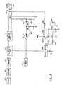
- Figure 5 is a schematic diagram of another form of the present invention.
- Figure 6 is a schematic diagram of still another form of the present invention.
- Figure 1 illustrates a prior art ferromagnetic strip B which may be 0.010 inches thick and 0.2 inches wide, composed of nickel-iron alloy having a permeability of over 100 and an effective Curie temperature in the range of 150°C or more. The constant current power supply PS is capable of delivering sufficient power to the strip to heat it well above the effective Curie temperature, for example 70°C above the effective Curie. If then the current is turned on, the strip B will be heated to temperature T (Fig. 4) which is say 70°C above the effective Curie C. If now a source of cooling fluid, for example gaseous carbon dioxide is passed over strip B in progressively increasing quantity the temperature will fall along line E to level C and will remain there until ultimately the cooling is so great that the temperature will fall off along tail line D.
- Figure 2 illustrates a similar prior art arrangement in which current is induced in ferromagnetic strip B by induction. This device will function in the same way as the device of Figure 1.
- In Figure 1 and 2, if the amplitude of the constant current is reduced so as to reduce the initial temperature T, say from 70°C above the effective Curie temperature, to say 10° above the effective Curie temperature, the flat part C of the curve will be greatly shortened and tail D will occur at a much smaller cooling rate.
- The present invention avoids the portion E of the curve above the effective Curie temperature and also either avoids tail line D or at least postpones it to such a high cooling rate that it is no problem.
- Referring to Figure 4, a ferromagneic strip or bar 10 has a diameter or thickness of at least several thousandths of an inch. The configuration of element 10 may vary depending on the desired end use. For example, if the end use is a soldering iron, element 10 may have the shape of a soldering iron.
- A small pick-up coil 11 is adjacent to, or around, a part, of ferromagnetic strip, bar or rod 10. Coil 11 will function as an auto-transformer. The left half of the coil 11 is the primary and the right half of the coil 11 is the secondary. When the ferromagnetic member 10 is below Curie the primary of coil 11 is fed by a 60Hz alternating
current source 19 such as the secondary of a small transformer fed by a 60Hz power line. The voltage ofsource 19 may be in the range of 8 to 24 volts. Thecontrol relay 16, 17 will be energized by the voltage or current induced in the secondary of auto-transformer 11 and will close the circuit to ferromagnetic member 10 when the ferromagnetic member 10 is below Curie. That is, below Curie, the ferromagnetic member 10 has high permeability and current will be induced in the secondary of auto-transformer 11. The secondary of auto-transformer 11 applies an a.c. voltage acrosswires 12 and 14. This voltage is rectified by rectifier 15 andfeeds relay coil 16, attracting armature 17 to close a circuit fromsource 18 through ferromagnetic member 10. The source may be in the range of 5 to 20 MHz, for example, and feeds sufficient RF current through member 10 to heat it well above Curie. As the member 10 is heated near or above Curie the auto-transformer 11 is no longer effective since the permeability of member 10 has dropped toward unity, hence the voltage in the secondary of the auto-transformer falls. Then, therelay coil 16 is deenergized and armature 17 opens the circuit under the pull of spring 20. Next, the current to the ferromagnetic member 10 from R.F.source 18 is cut-off. The ferromagnetic member 10 then cools and when its temperature falls below Curie the auto-transformer 11 again becomes operative due to the high permeability of member 10. The secondary of auto-transformer 11 now puts out full voltage, therelay 16, 17 closes and current fromsource 18 is again passed through member 10 to heat it above Curie. The cycle then repeats over and over. - Solid state controls may replace
parts 15, 16, 17. - The member 10 may be of high permeability such as Invar, Alloy 42, or a ternary alloy composed of 45% nickel, 46% iron and 9% molybdium.
- The parameters such as the amplitude of the current from
source 18, time delay etc. ofrelay 16, 17 may be selected so that therelay 16, 17 opens and closes rapidly (several times a second). In the solid state version, the time delay of the parts will be selected to get the proper frequency for the opening and closing of the solid state switch corresponding to relay 16, 17. If then there is a high rate of extraction of heat from member 10 therelay 16, 17 will be closed longer than it is open etc. But if onesection 21 of the member 10 has much more heat extracted therefrom than is extracted from other equally wide sections, thesection 21 will receive more heat from the current as will be explained. In such case, thesection 21 will remain far below Curie and will not rise above when the relay armature 17 is closed. Therefore, the skin depth of the current insection 21 will remain smaller than for the remainder of member 10. Hence,section 21 will have higher resistance per unit of length than the rest of member 10. Since the same current traverses the entire length of member 10,section 21 will get more heat per unit length, and thus provide more heat to offset the fact that there is greater extraction of heat fromsection 21. - R.F.
source 18 may be a constant current source but this is not necessary. The fact that it is disconnected from the load above Curie is sufficient control over the current. - A key point is that means are employed to detect the transition from below to above Curie and in response to detecting that transition the current thru the ferromagnetic bar is cut off. If the device is arranged to cycle on and off; and if the "off" periods are kept of short, the device should hold its temperature quite constant.
- In connection with Figure 4, it is preferable for the
relay 16, 17 to completely disconnect thesource 18 from the ferromagnetic strip 10. However, it would not depart from the broader aspects of the invention to reduce the current to the ferromagnetic element 10, whenrelay 16, 17 opens, instead of cutting the current clear off. This may be accomplished by placing a resistor across the contacts ofrelay 16, 17. - Figures 5 and 6, illustrate a different way of sensing the Curie transition. In these figures the change in power, that occurs when the temperature increases through the Curie transition is sensed, and in response to sensing that change in power, the current to the ferromagnetic element is either cut-off or reduced.
- In both Figures 5 and 6 the
load 69 is the high permeability ferromagnetic element and may have the composition, shape, and size described above, or as desired for any given end use. - Figure 5 illustrates a constant voltage power supply for use with the invention. This power supply has
conventional oscillator 50,conventional buffer 51,conventional driver 52, and conventionalclass C amplifier 53, stages. While a wide variety of such equipment is available, one suitable form is shown in The ARRL 1985 Handbook (62nd Ed., 1985), published by the American Radio Relay League, Chapter 30, pages 30-24 to 30-26. A copy of the applicable pages of this handbook is being filed with this application. Thedriver 52 has aninput 67 to key the same on and off and this corresponds to the key jack J1 on page 30-24 of said handbook. Preferably, thedriver 52 is keyed on contacts of a small fast electromagnetic relay (not shown) in a conventional fashion; the relay coil being energized byinput 67. - The
linear power amplifier 54 may be any, of many, suitable linear power amplifiers, for example it may be the 140 Watt Solid State Linear Amplifier, shown on pages 30-27 to 30-30 of said ARRL 1985 Handbook. See also the Motorola RF Data Manual (3rd. Ed., 1983), pages 4-194 to 4-199. The output oflinear power amplifier 54 is fed throughresistor 61, which feedsimpedance matching transformer 68 which in turn feeds theload 69. - The voltage at the output of the
linear power amplifier 54 is held constant by the components 55-60 as follows.Resistors power amplifier 54. Thediode 57feeds resistor 58 andcapacitor 81, andamplifier 59, so that the output of the latter reflects the voltage at the output ofpower amplifier 54. That output feedspower regulator 60 which may be Texas Instruments Inc. Type LM 117, described on pages 99 to 103 of The Voltage Regulator Handbook published by Texas Instruments, Inc. A copy of the applicable pages of this handbook are being filed with this application. Thisregulator 60 controls the mainpower input circuit 70 to theClass C amplifier 53 to thus raise or lower the output voltage thereof as necessary to keep the output voltage oflinear amplifier 54 fairly constant. Thisregulator 60 has a built-in conventional standard voltage reference source which is compared with the voltage at the output ofamplifier 59, and theregulator 60 then functions to hold the voltage at the output oflinear amplifier 54 constant. - If now the impedance of
ferromagnetic load element 69 drops due to a rise in temperature through the Curie transition, the current throughresistor 61 increases and the voltage at the input ofdiode 62 increase thereby increasing the voltage at the negative (-) input ofoperational amplifier 64, the output of which feedstimer 66 with a decreasing voltage which in turn opens the circuit atinput 67 ofdriver 52 turning off thedriver 52, theClass C amplifier 53 and the linear power amplifier for a time interval between 0.1 and 0.5 seconds, this time period being manually adjustable by varying saidtimer 66. At the end of the selected time interval thedriver 52 is turned on bytimer 66 and power to theload 69 resumes. Current will again flow throughresistor 61 to feed theload 69 and when the load impedance again drops the above process will repeat itself shutting off the power. In this way the power to theload 69 will pulsate as required. Timer 66 has a built in standard reference voltage which is compared with the voltage at the output ofamplifier 64, and the timer is triggered to start its time period when the voltage at the output ofamplifier 64 increases above the standard reference voltage. When this happens thetimer 66 opens the keyingcircuit 67 to cut-off all power at the output oflinear amplifier 54.- Figure 6 illustrates a constant current power supply suitable for use with the invention.
- The components for the constant current supply of Figure 6 are basically the same as for the constant voltage supply of Figure 5, and like reference numbers are used to represent like parts.
- The power generating stages 50 to 54 in Figure 6 are essentially the same as for Figure 5, although they are controlled in a different way; and therefore it is unnecessary to further describe those stages.
- The current from the output of
power amplifier 54 to theload 69 is held constant bycomponents resistor 61 increases the voltage drop across thatresistor 61 is fed to the input ofoperational amplifier 64 whose output controls power regulator 60 (which may be Texas Instruments, Inc. Type LM 117 described above). Thepower regulator 60 controls the voltage fed toClass C amplifier 53 to thus hold the output current ofpower amplifier 54 constant. As stated in connection with Figure 5 theregulator 60 has built-in standard reference voltage which is compared with the voltage at the output ofamplifier 64, and theregulator 60 functions to keep the two voltages the same and thus keep the current atload 69 constant. - When the load resistance of the load 69 (Fig. 6) falls, due to a rise in temperature through the Curie transition, the voltage at the output of
power amplifier 54 also fails (due to the constant-current circuit operational amplifier 59. The change in output of that amplifier is sensed by timer 66 (this being the same as the 555 timer referred to in connection with Figure 5) which then opens the keyingcircuit 67 ofdriver 52 and shuts off all power at the output of power amplifier for a timer interval between 0.1 and 0.5 seconds (thetimer 66 may be provided with a manual adjustment to enable one to select the time interval he wants). When the time interval is up, the power is restored and the cycle repeats itself. This continues as long as desired, with the result that a pulsating current is applied to theload 69. As stated in conjunction with Figure 5, thetimer 66 has a built-in standard reference voltage which is compared with the voltage at the output ofamplifier 59. When the voltage, at the output of amplifier 5° drops below the reference voltage, thetimer 66 cuts-off driver 52 for a predetermined time interval as explained in connection with Figure 5. - The
operational amplifiers - The
timer 66 of both Figures 5 and 6 may be Type 555 manufactured by Texas Instruments, Inc., and the manufacturer's data sheet for thistimer 66 is being filed with this application. When this form of timer is used the input signal is fed into the Trigger (pin 2) of thetimer 66. - The
impedance matching transformer 68 in both Figures 5 and 6 may be designed and/or selected according to conventional practices such as those described in said Motorola RF Device Data manual pages 4-145 to 4-153, or said ARRL 1985 Handbook, Figure 44, page 30-28. - The resistance values of the various resistors may be as follows; it being understood of course that changes are necessary for different designs:

Capacitors - In connection with Figure 4, 5 and 6 it is noted that the current fed to the
load 10 or 69, as the case may be, is not limited by the permissible temperature T (Fig. 3). The current that may be applied to theload 10 or 69 may be much higher than is permissible with Figures 1 and 2 or with any other known prior art. If a very large cooling load is applied toferromagnetic elements 10 or 69, the heavy current to those elements will be on a much larger percentage of the time than will be the case for a small cooling load. For example, if the cooling load is light, the heavy current will quickly reheat theferromagnetic load element 10 or 69, after the current is restored by the closing ofrelay 16, 17 or by the expiration of the time interval oftimer 66. But if the cooling load is very heavy the time period for heating the ferromagnetic load element after the current is turned on will be longer than was the case for the light load. - Thus, with the present invention, instead of the curve T,E,C,D of Figure 3, which is typical of the prior art, the curve would consist of a single horizontal substantially straight line at the effective Curie temperature G.
- Another advantage of the invention over the prior art referred to above, is that it will work over a very wide band of frequencies. For example, the device of Figure 4, will work, even if
power supply 18 has an output frequency as low as 60 Hz or even lower. In such a case the invention would lose the value of providing greater heat to a limited section 21 (Fig. 4), that is cooled more than other sections, if the strip or bar 10 or 69, is of small size. - The feature of providing increased heating to a limited section such as 21, is applicable to all forms of the invention (Figures 4, 5 and 6), if the frequency is high enough to provide the necessary change in skin depth. However, in connection with Figures 5 and 6 the frequency and the size of the ferromagnetic element should be so related that there is a substantial change in skin depth, due to the change in permeability, as the temperature goes through the Curie transition if a section such as 21 is to get added heat when it is cooled. A strip several thousandths of an inch thick will meet this requirement in the 8-20 MHz range. For any frequency the ferromagnetic load may be several skin depths thick, for example, to meet this requirement.
- The change in skin depth during the Curie transition will result in a change in resistance of the
load 69, which will result in a change in power, which is sensed and used as a control parameter. - The invention has end uses wherever it is desired to hold the temperature of a strip, rod, bar, or other configuration constant. One such use for example is in soldering as it is often undesirable to overheat apparatus being soldered. Hence, the
ferromagnetic element 10 or 69 may be all or part of an element being soldered, or it may be located in contact with an element being soldered. - The
ferromagnetic elements 10 or 69 may also be used as heaters to heat chemicals to make sure that chemical reactions occur at predetermined constant temperatures.


Claims (35)
providing an element composed of material having a parameter which changes in a predetermined way in response to an increase in temperature to a given temperature,
passing an electric current, of sufficient amplitude which if fed through said element for a prolonged period will heat said element well above said given temperature,
sensing said change in said predetermined way and reducing or turning off the flow of said current through said element in response to said change,
restoring said amplitude of said current to said element after a selected predetermined time,
said sensing and restoring steps recurring alternately at such a rate as to provide a pulsating current that holds said element at about said given temperature and at all times prevents a rise in the temperature of said element substantially above said given temperature.
an electrical conducting element having a parameter that changes in a predetermined way as the temperature of the element rises to a given temperature,
power delivery means feeding an electric current through said element of sufficient amplitude that if maintained indefinitely would heat said element far above said given temperature, and
means for repeatedly (a) sensing a change in said predetermined way and reducing or turning off said electric current to said element in response to the sensing of a change in said predetermined way during an increase in temperature of said element, and (b) subsequently restoring after a predetermined time interval said amplitude of said electric current to said element, to thereby produce a pulsating current that holds said element at about said given temperature.
a ferromagnetic element having a permeability substantial greater than one when its temperature is below its effective Curie temperature and a permeability on the order of one when its temperature is above its effective Curie temperature,
power delivery means feeding an electric current through said element of sufficient amplitude that if maintained indefinitely would heat said element far above its effective Curie temperature, so that said element has a Curie transition, and
means for sensing at least a part of said Curie transition and turning off said electric current to said element in response to the sensing of at least a part of said Curie transition during an increase in temperature of said element, and for subsequently restoring said electric current to said element.
said current being a current varying at a rate relative to the size of said element so that the current is concentrated along at least one surface of said element below the effective Curie temperature and spreads deeper into the element as the effective Curie temperature is approached so that if one part of the current carrying portion of said element is cooled more than another part of said element the said one part will receive increased heat due to the decreased skin depth of the current in such one part.
said element having a current carrying portion,
said current being a current varying at a rate relative to the size of said element so that the current is concentrated along at least one surface of said element below the effective Curie temperature and spreads deeper into the element as the effective Curie temperature is approached so that if one part of the current carrying portion of said element is cooled more than another part of said element the said one part will receive increased heat due to the decreased skin depth of the current in such one part.
providing an element composed of ferromagnetic material having a permeability considerably greater than one below its effective Curie temperature and a permeability on the order of one above its effective Curie temperature,
passing an alternating current through said element of sufficient magnitude to heat said element substantially above its effective Curie temperature so that said element has a Curie transition,
sensing at least a part of said Curie transition and stopping the flow of current in said element when at least a part of the Curie transition is sensed, and
restoring the current to said element when the temperature of said element falls and the permeability of said element increases substantially.
a ferromagnetic element having a permeability substantially greater than one when its temperature is below its effective Curie temperature and a permeability on the order of one when its temperature is above its effective Curie temperature,
power delivery means feeding an alternating current through said element of sufficient amplitude to heat said element above its effective Curie temperature, so that said element has at least part of a Curie transition, and
means for sensing at least a part of said Curie transition and turning off said alternating current to said element in response to the sensing of at least a part of said Curie transition during an increase in temperature of said element, and for subsequently restoring said alternating current to said element.
providing an element composed of ferromagnetic material having a permeability considerably greater than one below its effective Curie temperature and a permeability on the order of one above its effective Curie temperature,
passing an alternating current through said element of sufficient magnitude to heat said element substantially above its effective Curie temperature so that said element has at least part of a Curie transition, and
sensing at least a part of said Curie transition, by sensing a change in flux in said element and reducing the flow of current in said element when the flux is reduced.
a ferromagnetic element having a permeability substantially greater than one when its temperature is below its effective Curie temperature and a permeability on the order of one when its temperature is above its effective Curie temperature,
power delivery means feeding an alternating current through said element of sufficient amplitude to heat said element above its effective Curie temperature, so that said element has a Curie transition, and
means for sensing at least a part of said Curie transition by sensing a decrease in the magnetic flux in said element, and reducing said alternating current to said element in response to the sensing of a decrease flux in said element, and for subsequently restoring said alternating current to said element.
providing an element composed of ferromagnetic material having a permeability considerably greater than one below its effective Curie temperature and a permeability on the order of one above its effective Curie temperature,
passing an alternating current through said element of sufficient magnitude to heat said element substantially above its effective Curie temperature so that said element has a Curie transition thereby changing said power,
sensing at least a part of said Curie transition by sensing a change in power to said element and reducing and the flow of current to said element when said power declines, and
restoring the current to said element when the temperature of said element falls and the permeability of said element increases substantially,
the frequency of said alternating current and the size of said element being so related that the electrical resistance of said element to said alternating current substantially decreases as the temperature of said element rises through the Curie transition.
a ferromagnetic element having a permeability substantially greater than one when its temperature is below its effective Curie temperature and a permeability on the order of one when its temperature is above its effective Curie temperature,
power delivery means feeding an alternating current through said element of sufficient amplitude to heat said element above its effective Curie temperature, so that said element has a Curie transition, and
means for sensing at least a part of said Curie transition and for reducing said alternating current to said element in response to the sensing of a change in the power to said element, and for subsequently restoring said alternating current to said element,
the frequency of said alternating current and the size of said element being so related that the electrical resistance to said alternating current substantially decreases and said power changes as the temperature of said element is increasing and is going through a Curie transition.
providing an element composed of ferromagnetic material having a permeability considerably greater than one below its effective Curie temperature and a permeability on the order of one above its effective Curie temperature,
passing an electric current, of sufficient amplitude which if fed through said element for a prolonged period will heat said element well above its effective Curie temperature, to heat said element at least to a temperature high enough so that at least a part of the Curie transition takes place,
sensing at least part of said Curie transition and reducing the flow of said current through said element when at least part of said Curie transition is sensed, and
restoring said current to said element,
said sensing and restoring steps recurring alternately to thus provide a pulsating current that holds said element at about its effective Curie temperature and at all times prevents a rise in the temperature of said element substantially above its effective Curie temperature.
said current being an alternating current,
the frequency of said alternating current being so related to the size and permeability of said element that the skin depth of the alternating current flow increases when the temperature increases into the Curie transition to thus lower the effective resistance of said element to said alternating current, whereby the power fed to said element changes during the Curie transition,
said sensing step comprising sensing changes in the power of the alternating current fed to said element, to thereby sense at least part of the Curie transition during an increase in the temperature of said element and thereupon reduce the power fed to said element thereby limiting further heating of said element.
said sensing step including the sensing of changes in the other of said parameters to thus ascertain at least a part of the Curie transition and thereupon reduce the power fed to said element and limit the rise in temperature of said element.
Priority Applications (1)
| Application Number | Priority Date | Filing Date | Title |
|---|---|---|---|
| AT86303261TATE64481T1 (en) | 1985-06-28 | 1986-04-29 | FERROMAGNETIC ELEMENT WITH TEMPERATURE REGULATION. |
Applications Claiming Priority (2)
| Application Number | Priority Date | Filing Date | Title |
|---|---|---|---|
| US74963785A | 1985-06-28 | 1985-06-28 | |
| US749637 | 1996-11-15 |
Related Child Applications (1)
| Application Number | Title | Priority Date | Filing Date |
|---|---|---|---|
| EP90115677.8Division-Into | 1990-08-16 |
Publications (2)
| Publication Number | Publication Date |
|---|---|
| EP0209215A1true EP0209215A1 (en) | 1987-01-21 |
| EP0209215B1 EP0209215B1 (en) | 1991-06-12 |
Family
ID=25014561
Family Applications (2)
| Application Number | Title | Priority Date | Filing Date |
|---|---|---|---|
| EP86303261AExpired - LifetimeEP0209215B1 (en) | 1985-06-28 | 1986-04-29 | Ferromagnetic element with temperature regulation |
| EP90115677AWithdrawnEP0404209A1 (en) | 1985-06-28 | 1986-04-29 | Ferromagnetic element with temperature regulation |
Family Applications After (1)
| Application Number | Title | Priority Date | Filing Date |
|---|---|---|---|
| EP90115677AWithdrawnEP0404209A1 (en) | 1985-06-28 | 1986-04-29 | Ferromagnetic element with temperature regulation |
Country Status (5)
| Country | Link |
|---|---|
| EP (2) | EP0209215B1 (en) |
| JP (1) | JPH0815107B2 (en) |
| AT (1) | ATE64481T1 (en) |
| CA (1) | CA1251254A (en) |
| DE (1) | DE3679728D1 (en) |
Cited By (8)
| Publication number | Priority date | Publication date | Assignee | Title |
|---|---|---|---|---|
| GB2201319A (en)* | 1987-02-17 | 1988-08-24 | Bosch Siemens Hausgeraete | Electrical heating device controlled by a Curie point sensor |
| US5445635A (en)* | 1992-05-01 | 1995-08-29 | Hemostatic Surgery Corporation | Regulated-current power supply and methods for resistively-heated surgical instruments |
| US5480397A (en)* | 1992-05-01 | 1996-01-02 | Hemostatic Surgery Corporation | Surgical instrument with auto-regulating heater and method of using same |
| US5480398A (en)* | 1992-05-01 | 1996-01-02 | Hemostatic Surgery Corporation | Endoscopic instrument with disposable auto-regulating heater |
| FR2726961A1 (en)* | 1994-11-15 | 1996-05-15 | Europ Equip Menager | COOKING FIREPLACE WITH INDUCER PROTECTED IN TEMPERATURE |
| WO1996028955A1 (en)* | 1995-03-13 | 1996-09-19 | Raychem Corporation | Power source and method for induction heating of articles |
| US5593406A (en)* | 1992-05-01 | 1997-01-14 | Hemostatic Surgery Corporation | Endoscopic instrument with auto-regulating heater and method of using same |
| EP2209352A1 (en) | 2009-01-16 | 2010-07-21 | Whirpool Corporation | Induction cooking heater and method for the control thereof |
Families Citing this family (6)
| Publication number | Priority date | Publication date | Assignee | Title |
|---|---|---|---|---|
| JP3724857B2 (en)* | 1995-09-18 | 2005-12-07 | 株式会社瀬田技研 | Temperature control device and start method for electromagnetic induction heating device |
| US6384387B1 (en) | 2000-02-15 | 2002-05-07 | Vesture Corporation | Apparatus and method for heated food delivery |
| US6953919B2 (en) | 2003-01-30 | 2005-10-11 | Thermal Solutions, Inc. | RFID-controlled smart range and method of cooking and heating |
| US7573005B2 (en) | 2004-04-22 | 2009-08-11 | Thermal Solutions, Inc. | Boil detection method and computer program |
| JP5602278B1 (en)* | 2013-05-17 | 2014-10-08 | 中国電力株式会社 | Pillar failure detection area warning system |
| WO2015151151A1 (en)* | 2014-03-31 | 2015-10-08 | Sppテクノロジーズ株式会社 | Heating device and plasma treatment device provided with same |
Citations (6)
| Publication number | Priority date | Publication date | Assignee | Title |
|---|---|---|---|---|
| US3924102A (en)* | 1974-05-22 | 1975-12-02 | Nicolaas W Hanekom | Apparatus for controlling temperature |
| US4002882A (en)* | 1975-03-05 | 1977-01-11 | Mccutchen Charles W | Heating circuit |
| DE2806159B2 (en)* | 1978-02-14 | 1980-01-17 | Siemens Ag, 1000 Berlin Und 8000 Muenchen | Immersion heater |
| US4256945A (en)* | 1979-08-31 | 1981-03-17 | Iris Associates | Alternating current electrically resistive heating element having intrinsic temperature control |
| US4507546A (en)* | 1983-03-01 | 1985-03-26 | Fortune William S | Control circuit responsive to a component's varying resistance |
| US4546238A (en)* | 1982-02-08 | 1985-10-08 | Tocksfors Verkstads Ab | Circuit arrangement for temperature control of an electric heating element |
Family Cites Families (2)
| Publication number | Priority date | Publication date | Assignee | Title |
|---|---|---|---|---|
| JPS5457240A (en)* | 1977-10-15 | 1979-05-08 | Tdk Electronics Co Ltd | System of controlling temperature* etc* |
| JPS5769684A (en)* | 1980-10-16 | 1982-04-28 | Matsushita Electric Industrial Co Ltd | Temperature controller |
- 1986
- 1986-04-29DEDE8686303261Tpatent/DE3679728D1/ennot_activeExpired - Fee Related
- 1986-04-29EPEP86303261Apatent/EP0209215B1/ennot_activeExpired - Lifetime
- 1986-04-29EPEP90115677Apatent/EP0404209A1/ennot_activeWithdrawn
- 1986-04-29ATAT86303261Tpatent/ATE64481T1/enactive
- 1986-05-02JPJP61101269Apatent/JPH0815107B2/ennot_activeExpired - Lifetime
- 1986-06-20CACA000512138Apatent/CA1251254A/ennot_activeExpired
Patent Citations (6)
| Publication number | Priority date | Publication date | Assignee | Title |
|---|---|---|---|---|
| US3924102A (en)* | 1974-05-22 | 1975-12-02 | Nicolaas W Hanekom | Apparatus for controlling temperature |
| US4002882A (en)* | 1975-03-05 | 1977-01-11 | Mccutchen Charles W | Heating circuit |
| DE2806159B2 (en)* | 1978-02-14 | 1980-01-17 | Siemens Ag, 1000 Berlin Und 8000 Muenchen | Immersion heater |
| US4256945A (en)* | 1979-08-31 | 1981-03-17 | Iris Associates | Alternating current electrically resistive heating element having intrinsic temperature control |
| US4546238A (en)* | 1982-02-08 | 1985-10-08 | Tocksfors Verkstads Ab | Circuit arrangement for temperature control of an electric heating element |
| US4507546A (en)* | 1983-03-01 | 1985-03-26 | Fortune William S | Control circuit responsive to a component's varying resistance |
Cited By (11)
| Publication number | Priority date | Publication date | Assignee | Title |
|---|---|---|---|---|
| GB2201319A (en)* | 1987-02-17 | 1988-08-24 | Bosch Siemens Hausgeraete | Electrical heating device controlled by a Curie point sensor |
| US5445635A (en)* | 1992-05-01 | 1995-08-29 | Hemostatic Surgery Corporation | Regulated-current power supply and methods for resistively-heated surgical instruments |
| US5480397A (en)* | 1992-05-01 | 1996-01-02 | Hemostatic Surgery Corporation | Surgical instrument with auto-regulating heater and method of using same |
| US5480398A (en)* | 1992-05-01 | 1996-01-02 | Hemostatic Surgery Corporation | Endoscopic instrument with disposable auto-regulating heater |
| US5593406A (en)* | 1992-05-01 | 1997-01-14 | Hemostatic Surgery Corporation | Endoscopic instrument with auto-regulating heater and method of using same |
| FR2726961A1 (en)* | 1994-11-15 | 1996-05-15 | Europ Equip Menager | COOKING FIREPLACE WITH INDUCER PROTECTED IN TEMPERATURE |
| EP0713350A1 (en)* | 1994-11-15 | 1996-05-22 | Compagnie Europeenne Pour L'equipement Menager "Cepem" | Induction cooking surface with temperature protected inductor |
| US5665263A (en)* | 1994-11-15 | 1997-09-09 | C E P E M | Temperature-protected inductor-based cooking heater |
| WO1996028955A1 (en)* | 1995-03-13 | 1996-09-19 | Raychem Corporation | Power source and method for induction heating of articles |
| US5672290A (en)* | 1995-03-13 | 1997-09-30 | Raychem Corporation | Power source and method for induction heating of articles |
| EP2209352A1 (en) | 2009-01-16 | 2010-07-21 | Whirpool Corporation | Induction cooking heater and method for the control thereof |
Also Published As
| Publication number | Publication date |
|---|---|
| DE3679728D1 (en) | 1991-07-18 |
| JPH0815107B2 (en) | 1996-02-14 |
| CA1251254A (en) | 1989-03-14 |
| JPS625586A (en) | 1987-01-12 |
| EP0209215B1 (en) | 1991-06-12 |
| EP0404209A1 (en) | 1990-12-27 |
| ATE64481T1 (en) | 1991-06-15 |
Similar Documents
| Publication | Publication Date | Title |
|---|---|---|
| US4769519A (en) | Ferromagnetic element with temperature regulation | |
| EP0209215A1 (en) | Ferromagnetic element with temperature regulation | |
| USRE33644E (en) | Ferromagnetic element with temperature regulation | |
| KR920004082B1 (en) | Temperature control in which the control parameter is the degree of imperfection in the impedence matching | |
| EP0295011A2 (en) | Self regulating heater | |
| US4230971A (en) | Variable intensity control apparatus for operating a gas discharge lamp | |
| EP0852452A4 (en) | Temperature controller of electromagnetic induction heater and its start system | |
| US3270184A (en) | Temperature sensitive control wires provided with transistors for electrically heated pads, blankets and the like | |
| SE420148B (en) | HIGH-FREQUENCY HEATING DEVICE | |
| US4634958A (en) | Transformer utilizing selectively loaded reactance to control power transfer | |
| DE2427961C3 (en) | Temperature control device | |
| US4249068A (en) | Method and apparatus for controlling heat energy of a bonding transformer | |
| EP0434204B1 (en) | Heating of bearing and the like | |
| JP3187747B2 (en) | High frequency induction heating type soldering equipment | |
| US4215383A (en) | Current regulator for DC motors including sensitivity control means therefor | |
| US4015084A (en) | Protective device for induction heating apparatus | |
| US5162700A (en) | Controllable ballast and operating system utilizing same | |
| EP0180301B1 (en) | High efficiency autoregulating heater | |
| US3502021A (en) | Rolls for equipment for the pressure treatment of webs to remove moisture from the same | |
| US5380989A (en) | Inductive heating element with magnetic and thermistor materials | |
| US2453065A (en) | Electric regulation | |
| US4095076A (en) | Protective device for induction heating apparatus | |
| JPS6412492A (en) | High-frequency heating device | |
| US4412269A (en) | Lock out means in ignition devices for liquid fuel burners | |
| JP2687674B2 (en) | Cooker |
Legal Events
| Date | Code | Title | Description |
|---|---|---|---|
| PUAI | Public reference made under article 153(3) epc to a published international application that has entered the european phase | Free format text:ORIGINAL CODE: 0009012 | |
| AK | Designated contracting states | Kind code of ref document:A1 Designated state(s):AT BE CH DE FR GB IT LI SE | |
| 17P | Request for examination filed | Effective date:19870711 | |
| 17Q | First examination report despatched | Effective date:19890731 | |
| GRAA | (expected) grant | Free format text:ORIGINAL CODE: 0009210 | |
| AK | Designated contracting states | Kind code of ref document:B1 Designated state(s):AT BE CH DE FR GB IT LI SE | |
| PG25 | Lapsed in a contracting state [announced via postgrant information from national office to epo] | Ref country code:IT Free format text:LAPSE BECAUSE OF FAILURE TO SUBMIT A TRANSLATION OF THE DESCRIPTION OR TO PAY THE FEE WITHIN THE PRESCRIBED TIME-LIMIT;WARNING: LAPSES OF ITALIAN PATENTS WITH EFFECTIVE DATE BEFORE 2007 MAY HAVE OCCURRED AT ANY TIME BEFORE 2007. THE CORRECT EFFECTIVE DATE MAY BE DIFFERENT FROM THE ONE RECORDED. Effective date:19910612 Ref country code:BE Effective date:19910612 Ref country code:LI Effective date:19910612 Ref country code:AT Effective date:19910612 Ref country code:CH Effective date:19910612 Ref country code:SE Effective date:19910612 | |
| REF | Corresponds to: | Ref document number:64481 Country of ref document:AT Date of ref document:19910615 Kind code of ref document:T | |
| XX | Miscellaneous (additional remarks) | Free format text:TEILANMELDUNG 90115677.8 EINGEREICHT AM 29/04/86. | |
| REF | Corresponds to: | Ref document number:3679728 Country of ref document:DE Date of ref document:19910718 | |
| REG | Reference to a national code | Ref country code:CH Ref legal event code:PL | |
| EN | Fr: translation not filed | ||
| PG25 | Lapsed in a contracting state [announced via postgrant information from national office to epo] | Ref country code:FR Effective date:19911031 | |
| PLBE | No opposition filed within time limit | Free format text:ORIGINAL CODE: 0009261 | |
| STAA | Information on the status of an ep patent application or granted ep patent | Free format text:STATUS: NO OPPOSITION FILED WITHIN TIME LIMIT | |
| 26N | No opposition filed | ||
| REG | Reference to a national code | Ref country code:FR Ref legal event code:ST | |
| PGFP | Annual fee paid to national office [announced via postgrant information from national office to epo] | Ref country code:GB Payment date:19980420 Year of fee payment:13 | |
| PGFP | Annual fee paid to national office [announced via postgrant information from national office to epo] | Ref country code:DE Payment date:19980511 Year of fee payment:13 | |
| PG25 | Lapsed in a contracting state [announced via postgrant information from national office to epo] | Ref country code:GB Free format text:LAPSE BECAUSE OF NON-PAYMENT OF DUE FEES Effective date:19990429 | |
| GBPC | Gb: european patent ceased through non-payment of renewal fee | Effective date:19990429 | |
| PG25 | Lapsed in a contracting state [announced via postgrant information from national office to epo] | Ref country code:DE Free format text:LAPSE BECAUSE OF NON-PAYMENT OF DUE FEES Effective date:20000201 |