EP0209111A1 - Manipulator gear head - Google Patents
Manipulator gear headDownload PDFInfo
- Publication number
- EP0209111A1 EP0209111A1EP86109666AEP86109666AEP0209111A1EP 0209111 A1EP0209111 A1EP 0209111A1EP 86109666 AEP86109666 AEP 86109666AEP 86109666 AEP86109666 AEP 86109666AEP 0209111 A1EP0209111 A1EP 0209111A1
- Authority
- EP
- European Patent Office
- Prior art keywords
- gear
- head part
- axes
- head
- axis
- Prior art date
- Legal status (The legal status is an assumption and is not a legal conclusion. Google has not performed a legal analysis and makes no representation as to the accuracy of the status listed.)
- Granted
Links
- 230000009467reductionEffects0.000claimsabstractdescription19
- 230000001154acute effectEffects0.000claimsdescription4
- 230000008878couplingEffects0.000claimsdescription2
- 238000010168coupling processMethods0.000claimsdescription2
- 238000005859coupling reactionMethods0.000claimsdescription2
- 230000033001locomotionEffects0.000abstractdescription19
- 230000009471actionEffects0.000abstractdescription2
- 238000010276constructionMethods0.000description3
- 230000005540biological transmissionEffects0.000description2
- 230000000694effectsEffects0.000description2
- 239000013256coordination polymerSubstances0.000description1
- 238000006073displacement reactionMethods0.000description1
- 230000008030eliminationEffects0.000description1
- 238000003379elimination reactionMethods0.000description1
- 230000006872improvementEffects0.000description1
- 238000000034methodMethods0.000description1
- 230000008569processEffects0.000description1
- 238000005096rolling processMethods0.000description1
Images


Classifications
- F—MECHANICAL ENGINEERING; LIGHTING; HEATING; WEAPONS; BLASTING
- F16—ENGINEERING ELEMENTS AND UNITS; GENERAL MEASURES FOR PRODUCING AND MAINTAINING EFFECTIVE FUNCTIONING OF MACHINES OR INSTALLATIONS; THERMAL INSULATION IN GENERAL
- F16H—GEARING
- F16H1/00—Toothed gearings for conveying rotary motion
- F16H1/02—Toothed gearings for conveying rotary motion without gears having orbital motion
- F16H1/20—Toothed gearings for conveying rotary motion without gears having orbital motion involving more than two intermeshing members
- B—PERFORMING OPERATIONS; TRANSPORTING
- B25—HAND TOOLS; PORTABLE POWER-DRIVEN TOOLS; MANIPULATORS
- B25J—MANIPULATORS; CHAMBERS PROVIDED WITH MANIPULATION DEVICES
- B25J17/00—Joints
- B25J17/02—Wrist joints
- B25J17/0283—Three-dimensional joints
- B25J17/0291—Three-dimensional joints having axes crossing at an oblique angle, i.e. other than 90 degrees
- B—PERFORMING OPERATIONS; TRANSPORTING
- B25—HAND TOOLS; PORTABLE POWER-DRIVEN TOOLS; MANIPULATORS
- B25J—MANIPULATORS; CHAMBERS PROVIDED WITH MANIPULATION DEVICES
- B25J9/00—Programme-controlled manipulators
- Y—GENERAL TAGGING OF NEW TECHNOLOGICAL DEVELOPMENTS; GENERAL TAGGING OF CROSS-SECTIONAL TECHNOLOGIES SPANNING OVER SEVERAL SECTIONS OF THE IPC; TECHNICAL SUBJECTS COVERED BY FORMER USPC CROSS-REFERENCE ART COLLECTIONS [XRACs] AND DIGESTS
- Y10—TECHNICAL SUBJECTS COVERED BY FORMER USPC
- Y10T—TECHNICAL SUBJECTS COVERED BY FORMER US CLASSIFICATION
- Y10T74/00—Machine element or mechanism
- Y10T74/19—Gearing
- Y10T74/19642—Directly cooperating gears
- Y10T74/1966—Intersecting axes
- Y10T74/19665—Bevel gear type
Definitions
- the inventionrelates to a gear head for manipulators with the features specified in the preamble of claim (1)
- DE-OS 34 28 748describes a gear head for a manipulator consisting of three parts arranged one behind the other, the central head part of which has two oblique axes of rotation, each of which in the extended position of the gear head has an acute angle that opens in the opposite direction with the longitudinal axis of the gear head form.
- a step-up gearis arranged at the end of the individual gear train leading to the head parts.
- the gear headachieves a significantly increased range of motion with a compact construction of the gear head, because, due to the oblique rotatability of the rear head part relative to the central one, a significantly enlarged effective range of the tool is achieved. Since in this known case the output shaft is not coaxial with the drive shaft, ambiguities in the computer control are avoided.
- the object of the inventionis to expand the range of action and the possible application of the gear head and, in particular, to enable the rotation of the tool carrier within the rear gear head part without having to rotate the front head part about its axis.
- the inventioncomprises the basic idea of being able to carry out four different rotary movements on the gear head according to the invention with three drive shafts arranged concentrically to one another, namely the rotation of the front head part about the axis of the drive shafts, the rotation of the middle head part about the first oblique axis relative to the front head part 1 Turning the rear head part about the second inclined axis opposite the central head part and the rotation of the workpiece carrier within the rear head part.
- the inventionteaches to connect hollow shafts extending along the two inclined axes to one another by bevel gear sets and to drive them from a single drive motor.
- Fig. (1)corresponds to Fig. (1) of DE-OS 34 28 748 and is intended to clarify that there is an ambiguity for the arithmetic control when a tool carrier or a flange plate (38) in the rear gear head part (3) is rotatably mounted and driven about an output axis (46) lying coaxially to the drive axis (4). Then the rotation of the tool carrier about the output axis (46) would also be possible by turning the front gear head part (1) about the drive axis (4). In this case, this ambiguity could only be avoided if the front gear head part (1) were arranged non-rotatably about the axis (4).
- Fig. (2)shows a way of avoiding such an ambiguity by the output axis (46) is arranged at an acute angle obliquely to the drive axis (4).
- the output axis (46)should preferably intersect the intersection (9) of the two inclined axes (5, 6) in order to facilitate the calculation of the movement processes.
- bevel gears for driving the flange plate (38)are shown schematically. If a rotational movement of the tool carrier (38) about the axis (46) is to take place, this clarifies that the drive of the front gear head part (1) is not responsible for this. Ambiguity is avoided.
- Fig. (3) and (4)correspond to Figs. (2) and (4) of DE-OS 34 28 748. It can be seen that in both cases the rear head part (3) by the angle (2 ⁇ ) with respect to Drive axis (4) is pivoted, with different rotary drives being used. In the first case, the rear head part (3) is rotated by 180 ° with respect to the fixed, central head part (2). In the second case, the middle head part (2) with the rear head part (3) remaining in the same position relative to it is rotated by 180 ° with respect to the front head part (1). The resulting ambiguity can be eliminated with one of the variants according to Fig. (5) to (11).
- Fig. (6)it is shown that the inclined axis (5) is emphasized obliquely from the drawing plane in such a way that the intersection (9) of the two inclined axes (5) and (6) remains in the drawing plane.
- the oblique plane of rotationis symbolized by the ellipse (47) along which the two head parts (1, 2) are brought together.
- FIG. (7)extends this idea in that both oblique axes (5,6) are obliquely out of the drawing plane. All examples of FIGS. (5) to (7) show ways of avoiding the ambiguities indicated in FIGS. (3) and (4). In the case of FIG. 7, the point of intersection (9) of the oblique axes (5, 6) can lie away from the axis (4), or else in the drawing plane.
- Fig. (8)develops from the arrangement according to Fig (1) in that the oblique shafts (5,6) in the front and rear gear head part (1,3) are laterally offset until their axes are aligned cut in the drive shaft (4).
- the oblique position of the output axis (46 ") relative to the drive axis (4)is also shown, which - as said - eliminates the ambiguity of the control of these axes.
- the axis (46")can also coincide with Axis (6) brought and referred to as axis (46 '''), which on the one hand a reduction in the transmission transmission elements and thus the structural effort and on the other hand a reduction in the range of motion equals but is sufficient for many applications.
- the coaxiality of the axes (6) and (46 ''')does not cause any harmful, arithmetical ambiguity, because with simultaneous gear coupling of the axes (5) and (6) the latter has no function as a single axis.
- the output axis (46 ")is arranged obliquely, which has the consequence that it is not in alignment with the drive axis (4) in the drawing plane and thus arithmetic ambiguities do not arise.
- intersection (9 ') of the axes (4, 5, 6, 46', 46 '', 46 '' ') shown in FIGS. (8) to (11)can, according to the invention, be the center point of a ball or universal joint (49 ), by means of which the drive axle (4) is spatially movably connected to the output axle (46 ', 46 ", 46' '').
- This ball or universal joint (49)is shown symbolically. It permits several structural designs.
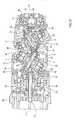
- FIGS. (12) to (14)constructional exemplary embodiments for the drive of the flange plate (38) are shown, starting from FIG. (1), the output axis (46) being coaxial in FIG. (12) and FIG. ( 13) is arranged parallel to the drive axis (4).
- Fig. (14)is the structural embodiment of Figs. (8 and 9).
- the intersection (9 ') of the axes (5,6)is the common end point of the axes (4) and (46', 46 ", 46 '' ').
- the oblique arrangement of the in the output axis (46", 46' '' ) lying, driving shaft (35)is mainly advantageous in so-called path-controlled manipulators in order to avoid arithmetical ambiguities.
- an inner drive shaft (13)is connected via the bevel gears (14, 15) to a hollow shaft (16) which is connected to the central head part (2) in a rotationally locking manner via a reduction gear (17).
- This middle head part (2)is rotated about the pivot axis (5) via this bevel gear arrangement (14, 15). It is guided via suitable bearings (40) on the front head part (1) about a plane perpendicular to the pivot axis (5).
- the outer drive shaft (26)acts via the reduction gear (27) directly on the front head part (1), which is arranged coaxially to the extension arm (28) and rotatably mounted on the latter. All reduction gears (17,25,27,36) are arranged on the output side, which is largely backlash-free, spatially compact and thus small-sized gear head construction results. These reduction gears (17,25,27,36) are intended for high reductions.
- a hollow shaft (32)is arranged along the second oblique pivot axis (6) and is connected to the preceding hollow shaft (16) via bevel gears (44, 45).
- the hollow shaft (16)drives the central head part (2) about the oblique pivot axis (5) via the step-up gear (17), which is supported on the front head part (1).
- the other hollow shaft (32)is supported by the step-up gear (25) on the central head part (2) and drives the rear head part (3) about the second, inclined pivot axis (6).
- Both gear ratios of the gears (17, 25)are of the same size and are preferably installed in mirror image to one another, which has the consequence that the head parts (2, 3) mounted on one another perform a simultaneous, but opposite, rotational movement when the hollow shafts (16, 32) rotate.
- the rear head part (3)is rotatably guided via the bearing (39) on the central head part (2), this via the bearing (40) on the front head part (1).
- the intermediate shaft (24)is guided on the output side via the bearing (41) on the rear head part (3) and on the drive side via the bearing (43) on the hollow shaft (32), which in turn is guided by the Bearing (42) is mounted on the central head part (2).
- a rear offset (48)can be provided in the rear head part for the mounting of the driving shaft (35), which cancels the lateral offset and thus ensures that the driving shaft (35) when the gear head (1,2,3) is in the extended position, it is coaxial to the drive axis (4).
- Fig. (14)shows a design embodiment for path-controlled manipulators to prevent arithmetical ambiguity, in which the oblique position of the output axis (46 ") is preferred.
- the output axis (46 ') - Fig. (14) -results from the Back offset (48) of the driving shaft (35) according to Fig. (13).
- the inclination of the output axis (46 ") to the drive axis (4)can not only be directed downwards as shown in Fig. 14, but also - as indicated by dash-dotted lines - upwards. Even a spatial inclination, for example in the drawing plane in or out of it is executable and would be used to solve the task.
Landscapes
- Engineering & Computer Science (AREA)
- Mechanical Engineering (AREA)
- Robotics (AREA)
- General Engineering & Computer Science (AREA)
- Manipulator (AREA)
- Gear Transmission (AREA)
- Gear-Shifting Mechanisms (AREA)
- Transmission Devices (AREA)
- Adjustment Of The Magnetic Head Position Track Following On Tapes (AREA)
- Accommodation For Nursing Or Treatment Tables (AREA)
Abstract
Description
Translated fromGermanDie Erfindung befaßt sich mit einem Getriebekopf für Manipulatoren mit den im Oberbegriff des Anspruches (1) angegebenen MerkmalenThe invention relates to a gear head for manipulators with the features specified in the preamble of claim (1)
Durch die DE-AS 27 45 932 ist es bekannt, einen Getriebekopf für einen Manipulator mit zwei hintereinander angeordneten Teilen auszuführen, wobei die beiden Kopfteile entlang einer schrägen Ebene aneinander drehbar gelagert sind. Der Werkzeugträger ist am hinteren Kopfteil längs einer zur Antriebsachse koaxialen Achse drehbar angeordnet.From DE-AS 27 45 932 it is known to design a gear head for a manipulator with two parts arranged one behind the other, the two head parts being rotatably supported on one another along an inclined plane. The tool carrier is rotatably arranged on the rear head part along an axis coaxial to the drive axis.
Diese Grundstellung in der gestreckten Lage des Getriebekopfes bringt Schwierigkeiten bei der rechnerisch gesteuerten Bewegung des Manipulators. Eine vom Programm vorgegebene Verdrehung des Werkzeuges um seine eigene Drehachse (6. Achse) läßt in der Durchführung der rechnerischen Vorgabe nämlich offen, ob der Getriebekopf um die Achse der konzentrischen Antriebswellen (4. Achse) oder ob der hintere Kopfteil für sich allein um diese Achse gedreht werden soll. Diese Zweideutigkeit wirkt sich insbesondere bei Bahnsteuerung (CP = continous path) negativ aus und konnte bisher nur durch programm- bzw. steuerungstechnische Manipulationen, allerdings nur unbefriedigend überwunden werden.
Bei PTP-Steuerung (Punkt-zu-Punkt-Steuerung) ist die koaxiale Anordnung der Drehachse des Werkzeugträgers (6. Achse) zu den konzentrischen Antrieswellen jedoch unproblematisch.This basic position in the extended position of the gear head causes difficulties in the computer-controlled movement of the manipulator. A rotation of the tool about its own axis of rotation (6th axis) specified by the program leaves open in the execution of the arithmetic specification whether the gear head around the axis of the concentric drive shafts (4th axis) or whether the rear head part alone around them Axis should be rotated. This ambiguity has a negative effect, in particular in the case of path control (CP = continuous path) and has so far only been able to be overcome by program or control engineering manipulations, but only unsatisfactorily.
With PTP control (point-to-point control), the coaxial arrangement of the axis of rotation of the tool holder (6th axis) to the concentric drive shafts is not problematic.
In der DE-OS 34 28 748 wird ein aus drei hintereinander angeordneten Teilen bestehender Getriebekopf für einen Manipulator beschrieben, dessen mittlerer Kopfteil zwei schräge Drehachsen aufweist, die in der Streckstellung des Getriebekopfes jeweils einen in entgegengesetzter Richtung sich öffnenden spitzen Winkel mit der Längsachse des Getriebekopfes bilden. Am Ende des einzelnen zu den Kopfteilen führenden Getriebezuges ist jeweils ein hochuntersetzendes Getriebe angeordnet.DE-OS 34 28 748 describes a gear head for a manipulator consisting of three parts arranged one behind the other, the central head part of which has two oblique axes of rotation, each of which in the extended position of the gear head has an acute angle that opens in the opposite direction with the longitudinal axis of the gear head form. At the end of the individual gear train leading to the head parts, a step-up gear is arranged.
Mit einer solchen Gestaltung erlangt der Getriebekopf einen wesentlich vergrößerten Bewegungsspielraum bei kompakter Bauweise des Getriebekopfes, denn zufolge der schrägen Verdrehbarkeit des hinteren Kopfteils gegenüber dem mittleren wird ein wesentlich vergrößerter Wirkbereich des Werkzeuges erreicht. Da in diesem bekannten Fall die Abtriebswelle nicht koaxial zur Antriebswelle liegt, werden Zweideutigkeiten in der rechnerischen Steuerung vermieden.With such a design, the gear head achieves a significantly increased range of motion with a compact construction of the gear head, because, due to the oblique rotatability of the rear head part relative to the central one, a significantly enlarged effective range of the tool is achieved. Since in this known case the output shaft is not coaxial with the drive shaft, ambiguities in the computer control are avoided.
Mit der Erfindung wird die Aufgabe gestellt, den Aktionsbereich und die Anwendungsmöglichkeit des Getriebekopfes noch zu erweitern und insbesondere die Rotation des Werkzeugträgers innerhalb des hinteren Getriebekopfteiles zu ermöglichen, ohne den vorderen Kopfteil um seine Achse drehen zu müssen.The object of the invention is to expand the range of action and the possible application of the gear head and, in particular, to enable the rotation of the tool carrier within the rear gear head part without having to rotate the front head part about its axis.
Diese Aufgabe wird, ausgehend von der DE-OS 34 28 748,mit den kennzeichnenden Merkmalen des Hauptanspruches gelöst.This object is achieved on the basis of DE-OS 34 28 748 with the characterizing features of the main claim.
Die Erfindung umfaßt den Grundgedanken, mit drei konzentrisch zueinander angeordneten Antriebswellen vier verschiedene Drehbewegungen am erfindungsgemäßen Getriebekopf ausführen zu können, nämlich das Drehen des vorderen Kopfteiles um die Achse der Antriebswellen, das Drehen des mittleren Kopfteiles um die erste schräge Achse gegenüber dem vorderen Kopftei1, das Drehen des hinteren Kopfteiles um die zweite schräge Achse gegenüber dem mittleren Kopfteil und das Drehen des Werkstückträgers innerhalb des hinteren Kopfteiles. Hierzu lehrt die Erfindung, längs der beiden schrägen Achsen sich erstreckende Hohlwellen durch Kegelradsätze miteinander zu verbinden und von einem einzigen Antriebsmotor aus anzutreiben. Da diese Hohlwellen über Untersetzungsgetriebe am vorderen bzw. mittleren Kopfteil abgestützt sind, wobei die Getriebe gleichgroße Untersetzung besitzen, und da die Kopfteile aneinandergelagert sind, führt die Rotation der Hohlwellen zu einer gleichzeitigen, aber gegensinnigen Drehbewegung des hinteren und mittleren Kopfteiles um die schrägen Achsen. Zufolge dieser Hohlwellen-Konstruktion ist nun die Möglichkeit geschaffen, einen Getriebezug von einer innenliegenden Antriebswelle durch die Hohlwellen bis zu einer im letzten Kopfteil gelagerten, treibenden Welle zu führen, die mit dem Werkzeugträger verbunden ist.The invention comprises the basic idea of being able to carry out four different rotary movements on the gear head according to the invention with three drive shafts arranged concentrically to one another, namely the rotation of the front head part about the axis of the drive shafts, the rotation of the middle head part about the first oblique axis relative to the
Durch die DE-OS 34 31 033 ist es bei einem drei Kopfteile aufweisenden Getriebekopf zwar ebenfalls bekannt, eine mit dem Werkzeugträger verbundene Welle koaxial zur Antriebswelle (bei gestreckter Getriebekopfstellung) zu lagern und anzutreiben, wozu hohle Wellen und Kegelräder verwendet werden, um durch den Innenraum Kabel, Schläuche, Leitungen oder dgl. zu führen. Bei dieser Anordnung wird der hintere Kopfteil nicht unmittelbar angetrieben, sondern über einen schrägen Kegelradzahnkranz mit einem am vorderen Kopfteil befindlichen Zahnkranz gekoppelt, wobei der punktuelle Zahneingriff außerhalb des mittleren Kopfteiles liegt. Wenn also der mittlere Kopfteil verdreht wird, ist der hintere Kopfteil zufolge seiner Lagerung am mittleren Kopfteil bestrebt, dieser Drehung zu folgen. Da aber der punktuelle Zahneingriff mit dem vorderen Kopfteil vorliegt, erfolgt am Zahnkranz des unbeweglich gehaltenen vorderen Kopfteiles eine Abwälzbewegung des hinteren Kopfteiles, was zu einer Taumelbewegung des hinteren Kopfteiles führt. Wenn hingegen der vordere Kopfteil verdreht wird, führt zugleich der hintere Kopfteil eine unerwünschte Eigendrehbewegung mit angenähert gleichgroßem Drehwinkel aus. Die Eigendrehbewegung ist die Folge von Relativdrehbewegungen der ineinander gelagerten und sich deshalb beeinflußenden Getriebeteile. Außerdem entsteht ein erheblicher negativer Einfluß der Verzahnungsfehler und des Verzahnungsspiels auf die räumliche Zuordnung der Kopfteile dadurch, daß beim vorbekannten Getriebekopf hochuntersetzende Getriebe abtriebsseitig nicht vorgesehen sind, die eine Reduzierung der Fehler, und der Wirkung der Relativdrehbewegungen bewirken könnten.From DE-OS 34 31 033 it is also known in a gear head having three head parts to mount and drive a shaft connected to the tool carrier coaxially to the drive shaft (when the gear head position is extended), for which purpose hollow shafts and bevel gears are used to drive through Guide cables, hoses, lines or the like inside. In this arrangement, the rear head part is not driven directly, but is coupled via an oblique bevel gear ring gear to a ring gear located on the front head part, the point-to-point tooth engagement lying outside the central head part. If the middle head part is rotated, the rear head part tends to follow this rotation due to its position on the middle head part. However, since there is a punctiform tooth engagement with the front head part, one takes place on the ring gear of the immobile front head part Rolling movement of the rear head part, which leads to a wobbling movement of the rear head part. If, on the other hand, the front head part is rotated, the rear head part simultaneously performs an undesired self-rotating movement with an approximately equally large angle of rotation. The self-rotating movement is the result of relative rotary movements of the gear parts which are mounted one inside the other and therefore influence one another. In addition, there is a considerable negative influence of the gear errors and the gear backlash on the spatial assignment of the head parts in that the prior art gear head does not provide high-reduction gears on the output side, which could reduce the errors and the effect of the relative rotary movements.
Bei der Erfindung wird hingegen eine wesentliche Verbesserung dadurch erreicht, daß innenliegende, ölbadgeschmierte Verzahnungen und Abstützungen durch abtriebsseitige hochuntersetzende Untersetzungsgetriebe verwendet werden, was zu einer sehr kompakten Bauweise mit höherer und über lange Zeit konstanter Genauigkeit der Bewegungen führt. Relativdrehbewegungen sind nur noch im Untersetzungsverhältnis wirksam und durch die Steuerung zu kompensieren.In the invention, however, a significant improvement is achieved in that internal, oil bath-lubricated gears and supports are used by the reduction gear on the output side, which leads to a very compact design with a higher and constant accuracy of the movements over a long time. Relative rotary movements are only effective in the reduction ratio and must be compensated for by the control.
Mit der Erfindung wurde außerdem erkannt, daß die mit der Lehre der DE-OS 34 28 748 offenbarte Beseitigung der rechnerischen Zweideutigkeit nicht die einzig mögliche ist und zwar insbesondere dann, wenn der Werkzeugträger bzw. die Flanschplatte im hinteren Kopfteil drehbar gelagert und angetrieben ist. Die in den Unteransprüchen (5) bis (10) angegebenen Merkmale zeigen noch weitere Möglichkeiten zur Beseitigung rechnerischer Zweideutigkeiten.With the invention it was also recognized that the elimination of the computational ambiguity disclosed with the teaching of DE-OS 34 28 748 is not the only possible one, in particular when the tool carrier or the flange plate in the rear head part is rotatably supported and driven. The features specified in subclaims (5) to (10) show further possibilities for eliminating computational ambiguities.
Einzelheiten der Erfindung sind in der Zeichnung schematisch und beispielsweise dargestellt. Es zeigen:
- Fig. 1: eine symbolische Seitenansicht eines Getriebekopfes in seiner gestreckten Lage,
- Fig.2: eine Seitenansicht gemäß Fig. 1 mit schräg angeordnetem Abtrieb,
- Fig.3 und 4: Seitenansichten des Getriebekopfes in übereinstimmenden Schwenkstellungen,
- Fig. 5 bis 11: Ansichten verschiedener Getriebeköpfe mit in besonderer Weise angeordneten, schrägen Achsen und
- Fig. 12 bis 14: Langsschnitte durch drei konstruktive Ausführungsbeispiele.
- 1: a symbolic side view of a gear head in its extended position,
- 2: a side view according to FIG. 1 with angled output,
- 3 and 4: side views of the gear head in matching pivot positions,
- 5 to 11: Views of different gear heads with inclined axes and arranged in a special way
- 12 to 14: longitudinal sections through three constructive exemplary embodiments.
Die Fig. (1) entspricht der Fig. (1) der DE-OS 34 28 748 und soll verdeutlichen, daß eine Zweideutigkeit für die rechnerische Steuerung vorhanden ist, wenn im hinteren Getriebekopfteil (3) ein Werkzeugträger bzw. eine Flanschplatte (38) um eine koaxial zur Antriebsachse (4) liegende Abtriebsachse (46) drehbar gelagert und angetrieben ist. Dann würde nämlich die Verdrehung des Werkzeugträgers um die Abtriebsachse (46) auch durch Verdrehung des vorderen Getriebekopfteiles (1) um die Antriebsachse (4) möglich sein. Diese Zweideutigkeit würde sich in diesem Fall nur dann vermeiden lassen, wenn der vordere Getriebekopfteil (1) um die Achse (4) unverdrehbar angeordnet wäre.Fig. (1) corresponds to Fig. (1) of DE-OS 34 28 748 and is intended to clarify that there is an ambiguity for the arithmetic control when a tool carrier or a flange plate (38) in the rear gear head part (3) is rotatably mounted and driven about an output axis (46) lying coaxially to the drive axis (4). Then the rotation of the tool carrier about the output axis (46) would also be possible by turning the front gear head part (1) about the drive axis (4). In this case, this ambiguity could only be avoided if the front gear head part (1) were arranged non-rotatably about the axis (4).
Mit (5) und (6) sind schräge Schwenkachsen bezeichnet, um welche die Relativdrehbewegung des mittleren Getriebekopfteiles (2) gegenüber dem vorderen bzw. hinteren Getriebekopfteil (1,3) stattfindet.With (5) and (6) oblique pivot axes are designated, around which the relative rotational movement of the central gear head part (2) relative to the front and rear gear head part (1,3) takes place.
Fig. (2) zeigt eine Möglichkeit der Vermeidung einer solchen Zweideutigkeit auf, indem die Abtriebsachse (46) im spitzen Winkel schräg zur Antriebsachse (4) angeordnet ist. Vorzugsweise soll die Abtriebsachse (46) den Schnittpunkt (9) der beiden schrägen Achsen (5,6) schneiden, um die Rechnung der Bewegungsvorgänge zu erleichtern. Mit (33) und (34) sind schematisch Kegelräder zum Antrieb der Flanschplatte (38) dargestellt. Soll eine Drehbewegung des Werkzeugträgers (38) um die Achse (46) stattfinden, ist damit klargestellt, daß hierfür nicht der Antrieb des vorderen Getriebekopfteiles (1) zuständig ist. Zweideutigkeit ist also vermieden.Fig. (2) shows a way of avoiding such an ambiguity by the output axis (46) is arranged at an acute angle obliquely to the drive axis (4). The output axis (46) should preferably intersect the intersection (9) of the two inclined axes (5, 6) in order to facilitate the calculation of the movement processes. With (33) and (34), bevel gears for driving the flange plate (38) are shown schematically. If a rotational movement of the tool carrier (38) about the axis (46) is to take place, this clarifies that the drive of the front gear head part (1) is not responsible for this. Ambiguity is avoided.
Die Fig. (3) und (4) entsprechen den Fig. (2) und (4) der DE-OS 34 28 748. Man erkennt, daß in beiden Fällen der hintere Kopfteil (3) um den Winkel (2α) gegenüber der Antriebsachse (4) geschwenkt ist, wobei unterschiedliche Drehantriebe verwendet werden. Im ersten Fall wird der hintere Kopfteil (3) um 180° gegenüber dem feststehenden, mittleren Kopfteil (2) gedreht. Im zweiten Fall wird der mittlere Kopfteil (2) mit dem ihm gegenüber in gleicher Lage verbleibenden, hinteren Kopfteil (3) um 180° gegenüber dem vorderen Kopfteil (1) verdreht. Die dadurch gegebene Zweideutigkeit läßt sich mit einer der Varianten nach Fig. (5) bis (11) beseitigen.Fig. (3) and (4) correspond to Figs. (2) and (4) of DE-OS 34 28 748. It can be seen that in both cases the rear head part (3) by the angle (2α) with respect to Drive axis (4) is pivoted, with different rotary drives being used. In the first case, the rear head part (3) is rotated by 180 ° with respect to the fixed, central head part (2). In the second case, the middle head part (2) with the rear head part (3) remaining in the same position relative to it is rotated by 180 ° with respect to the front head part (1). The resulting ambiguity can be eliminated with one of the variants according to Fig. (5) to (11).
Beim Beispiel der Fig (5) sind die Winkel (α₁) und (α₂) der beiden schrägen Achsen (5) und (6) ungleich groß, weshalb ihr Schnittpunkt (9) aus der Symmetriestellung der Fig. (1) seitlich versetzt zu liegen kommt. Die gleichen Verdrehungen der Kopfteile (2) und (3) führen somit zu voneinander unterschiedlichen Winkelstellungen.In the example of Fig. (5), the angles (α₁) and (α₂) of the two inclined axes (5) and (6) are unequal in size, which is why their intersection (9) is laterally offset from the symmetry position of FIG. (1) is coming. The same rotations of the head parts (2) and (3) thus lead to different angular positions.
In Fig. (6) ist gezeigt, daß die schräge Achse (5) in der Weise aus der Zeichenblattebene schräg herausgestellt ist, daß der Schnittpunkt (9) der beiden schrägen Achsen (5) und (6) in der Zeichenblattebene verbleibt. Durch die Ellipse (47) ist die schräge Rotationsebene symbolisiert, entlang welcher die beiden Kopfteile (1,2) aneinandergeführt sind.In Fig. (6) it is shown that the inclined axis (5) is emphasized obliquely from the drawing plane in such a way that the intersection (9) of the two inclined axes (5) and (6) remains in the drawing plane. The oblique plane of rotation is symbolized by the ellipse (47) along which the two head parts (1, 2) are brought together.
Die. Fig. (7) erweitert diesen Gedanken, indem beide schräge Achsen (5,6) aus der Zeichenblattebene schräg herausgestellt sind. Sämtliche Beispiele der Fig. (5) bis (7) zeigen Möglichkeiten zur Vermeidung der in Fig. (3) und (4) angegebenen Zweideutigkeiten auf. Im Fall der Fig (7) kann der Schnittpunkt (9) der schrägen Achsen (5,6) abseits der Achse (4), oder aber auch in der Zeichenblattebene liegen.The. Fig. (7) extends this idea in that both oblique axes (5,6) are obliquely out of the drawing plane. All examples of FIGS. (5) to (7) show ways of avoiding the ambiguities indicated in FIGS. (3) and (4). In the case of FIG. 7, the point of intersection (9) of the oblique axes (5, 6) can lie away from the axis (4), or else in the drawing plane.
Eine bedeutsame Erleichterung der Berechnung automatischer Bewegungssteuerungen ergibt sich dann, wenn der Schnittpunkt (9') der schrägen Achsen (5,6) auf der Achse (4) liegt und wenn die Abtriebsachse (46', 46", 46''') diesen Schnittpunkt (9') schneidet. Zur Verdeutlichung der Offenbarung sei angeführt, daß in den hierfür angegebenen Beispielen der Fig. (8) bis (11) die Abtriebsachse (46) die Bezeichnung (46') erhält, wenn sie koaxial zur Antriebsachse (4) liegt und den Punkt (9') schneidet (Fig. 8 und 10). Sie erhält die Bezeichnung (46"), wenn sie einen Winkel mit der Antriebsachse (4) bildet, aber auch den Punkt (9') schneidet (Fig. 9 und 10).The calculation of automatic motion controls is significantly facilitated if the intersection (9 ') of the inclined axes (5,6) lies on the axis (4) and if the output axis (46', 46 ", 46 '' ') does so In order to clarify the disclosure, it should be mentioned that in the examples given for this in FIGS. (8) to (11) the output axis (46) is given the designation (46 ') when it is coaxial with the drive axis (4th ) lies and intersects point (9 ') (FIGS. 8 and 10). It receives the designation (46 ") when it forms an angle with the drive axis (4) but also intersects point (9') (FIG . 9 and 10).
Die Gestaltung nach Fig. (8) entwickelt sich aus der Anordnung nach Fig (1) dadurch, daß die schrägen Wellen (5,6) in dem vorderen und hinteren Getriebekopfteil (1,3) soweit seitlich versetzt gelagert sind, bis ihre Achsen sich in der Antriebsachse (4) schneiden.The design according to Fig. (8) develops from the arrangement according to Fig (1) in that the oblique shafts (5,6) in the front and rear gear head part (1,3) are laterally offset until their axes are aligned cut in the drive shaft (4).
Im Beispiel der Fig. (9) ist zusätzlich die schräge Lage der Abtriebsachse (46") zur Antriebsachse (4) gezeigt, was - wie gesagt - die Zweideutigkeit der Ansteuerung dieser Achsen beseitigt. Die Achse (46") kann auch zur Deckung mit Achse (6) gebracht und als Achse (46''') bezeichnet werden, was einerseits einer Reduzierung der getrieblichen Übertragungselemente und damit des baulichen Aufwandes und andererseits einer Verkleinerung des Bewegungsspielraumes gleichkommt aber für viele Einsatzfälle ausreichend ist.
Eine schädliche, rechnerische Zweideutigkeit entsteht durch die Koaxialität der Achsen (6) und (46''') nicht, weil bei gleichzeitiger getrieblicher Kopplung der Achsen (5) und (6) letztere als Einzelachse keine Funktion hat.In the example of FIG. (9), the oblique position of the output axis (46 ") relative to the drive axis (4) is also shown, which - as said - eliminates the ambiguity of the control of these axes. The axis (46") can also coincide with Axis (6) brought and referred to as axis (46 '''), which on the one hand a reduction in the transmission transmission elements and thus the structural effort and on the other hand a reduction in the range of motion equals but is sufficient for many applications.
The coaxiality of the axes (6) and (46 ''') does not cause any harmful, arithmetical ambiguity, because with simultaneous gear coupling of the axes (5) and (6) the latter has no function as a single axis.
Die Fig. (8) und (9) gehen davon aus, daß die Achsen (4,5,6,46 ,46",46''') in der Streckstellung des Getriebekopfes in der Zeichenblattebene liegen. Im Falle der Fig. (8) wäre die zu Fig. (3) und (4) festgestellte Zweideutigkeit noch nicht beseitigt. Wie man aber aus Fig. (6) und (7) weiß, läßt sich diese Zweideutigkeit durch schräg aus der Zeichenblattebene herausgestellte Achsen (5,6) beseitigen. Diese Maßnahme im Zusammenhang mit der koaxialen Lage des Schnittpunktes (9') der Achsen (4,5,6,46',46'',46''') führt zu den Ausführungsbeispielen der Fig. (10) und (11). Die Fig. (10) und (11) zeigen eine Variante zu Fig. (7) in Seitenansicht und Draufsicht, wobei die einzelnen Kopfteile (1,2) und (3) seitlich auskragende Gehäuseteile zur Lagerung der schrägen, aus der Zeichenblattebene nach hinten und vorne herausragenden Achsen (5,6) aufweisen und der Schnittpunkt (9') dieser schrägen Achsen (5,6) in der Zeichenblattebene liegt und gemeinsamer Endpunkt der Achsen (4) und (46',46") ist. Außerdem ist die Abtriebsachse (46") schräg angeordnet, was zur Folge hat, daß sie nicht fluchtend zur Antriebsachse (4) in der Zeichenblattebene liegt und somit rechnerische Zweideutigkeiten nicht entstehen.(8) and (9) assume that the axes (4,5,6,46, 46 ", 46 ''') are in the extended position of the gear head in the plane of the drawing sheet. In the case of Fig. ( 8) the ambiguity found for Fig. (3) and (4) would not have been eliminated, but as is known from Fig. (6) and (7), this ambiguity can be determined by axes (5,6 This measure in connection with the coaxial position of the intersection (9 ') of the axes (4,5,6,46', 46 '', 46 ''') leads to the exemplary embodiments of FIGS. (10) and ( 11). (10) and (11) show a variant of Fig. (7) in side view and top view, the individual head parts (1, 2) and (3) projecting laterally projecting housing parts for mounting the oblique from the Have drawing plane plane projecting axes (5,6) to the rear and front and the intersection (9 ') of these oblique axes (5,6) lies in the drawing plane plane and is the common end point of the axes (4) and (46', 46 "). In addition, the output axis (46 ") is arranged obliquely, which has the consequence that it is not in alignment with the drive axis (4) in the drawing plane and thus arithmetic ambiguities do not arise.
Der in den Fig. (8) bis (11) gezeigte Schnittpunkt (9') der Achsen (4,5,6,46',46'',46''') kann erfindungsgemäß der Mittelpunkt eines Kugel- oder Kardangelenkes (49) sein, über welches die Antriebsachse (4) mit der Abtriebsachse (46',46",46''') räumlich beweglich verbunden ist. Dieses Kugel oder Kardangelenk (49) ist symbolisch dargestellt. Es läßt mehrere konstruktive Gestaltungen zu.The intersection (9 ') of the axes (4, 5, 6, 46', 46 '', 46 '' ') shown in FIGS. (8) to (11) can, according to the invention, be the center point of a ball or universal joint (49 ), by means of which the drive axle (4) is spatially movably connected to the output axle (46 ', 46 ", 46' ''). This ball or universal joint (49) is shown symbolically. It permits several structural designs.
In den Fig. (12) bis (14) sind konstruktive Ausführungsbeispiele für den Antrieb der Flanschplatte (38), ausgehend von Fig. (1) gezeigt, wobei in Fig. (12) die Abtriebsachse (46) koaxial und in Fig. (13) parallel zur Antriebsachse (4) angeordnet ist. Fig. (14) ist das konstruktive Ausführungsbeispiel der Fig. (8 und 9). Der Schnittpunkt (9') der Achsen (5,6) ist gemeinsamer Endpunkt der Achsen (4) und (46',46",46''' ). Die schräge Anordnung der in der Abtriebsachse (46",46''' ) liegenden, treibenden Welle (35) ist hauptsächlich bei sogenannten bahngesteuerten Manipulatoren vorteilhaft, um rechnerische Zweideutigkeiten zu vermeiden. Im konstruktiven Ausführungsbeispiel ist eine innere Antriebswelle (13) über die Kegelräder (14,15) mit einer Hohlwelle (16) verbunden, welche über ein Untersetzungsgetriebe (17) mit dem mittleren Kopfteil (2) drehschlüssig verbunden ist. Dieser mittlere Kopfteil (2) wird über diese Kegelradanordnung (14,15) um die Schwenkachse (5) gedreht. Er ist über geeignete Lagerungen (40) am vorderen Kopfteil (1) um eine zur Schwenkachse (5) senkrechte Ebene geführt.In FIGS. (12) to (14), constructional exemplary embodiments for the drive of the flange plate (38) are shown, starting from FIG. (1), the output axis (46) being coaxial in FIG. (12) and FIG. ( 13) is arranged parallel to the drive axis (4). Fig. (14) is the structural embodiment of Figs. (8 and 9). The intersection (9 ') of the axes (5,6) is the common end point of the axes (4) and (46', 46 ", 46 '' '). The oblique arrangement of the in the output axis (46", 46' '' ) lying, driving shaft (35) is mainly advantageous in so-called path-controlled manipulators in order to avoid arithmetical ambiguities. In the design embodiment, an inner drive shaft (13) is connected via the bevel gears (14, 15) to a hollow shaft (16) which is connected to the central head part (2) in a rotationally locking manner via a reduction gear (17). This middle head part (2) is rotated about the pivot axis (5) via this bevel gear arrangement (14, 15). It is guided via suitable bearings (40) on the front head part (1) about a plane perpendicular to the pivot axis (5).
Die außere Antriebswelle (26) wirkt über das Untersetzungsgetriebe (27) direkt auf den vorderen Kopfteil (1) ein, der koaxial zum Auslegerarm (28) angeordnet und an diesem drehbar gelagert ist. Sämtliche Untersetzungsgetriebe (17,25,27,36) sind abtriebsseitig angeordnet, was eine weitgehend spielfreie, räumlich kompakte und damit kleinbauende Getriebekopfkonstruktion zur Folge hat. Diese Untersetzungsgetriebe (17,25,27,36) sind für hohe Untersetzungen vorgesehen.
Längs der zweiten, schrägen Schwenkachse (6) ist eine Hohlwelle (32) angeordnet, die mit der ihr vorausgehenden Hohlwelle (16) über Kegelräder (44,45) verbunden ist. Die Hohlwelle (16) treibt über das hochuntersetzende Getriebe (17), das sich am vorderen Kopfteil (1) abstützt, den mittleren Kopfteil (2) um die schräge Schwenkachse (5) an. Die andere Hohlwelle (32) stützt sich mit dem hochuntersetzenden Getriebe (25) am mittleren Kopfteil (2) ab und treibt den hinteren Kopfteil (3) um die zweite, schräge Schwenkachse (6) an. Beide Untersetzungen der Getriebe (17,25) sind gleich groß und werden bevorzugt spiegelbildlich zueinander eingebaut, was zur Folge hat, daß die aneinandergelagerten Kopfteile (2,3) bei Rotation der Hohlwellen (16,32) eine gleichzeitige, aber gegensinnige Drehbewegung ausführen.The outer drive shaft (26) acts via the reduction gear (27) directly on the front head part (1), which is arranged coaxially to the extension arm (28) and rotatably mounted on the latter. All reduction gears (17,25,27,36) are arranged on the output side, which is largely backlash-free, spatially compact and thus small-sized gear head construction results. These reduction gears (17,25,27,36) are intended for high reductions.
A hollow shaft (32) is arranged along the second oblique pivot axis (6) and is connected to the preceding hollow shaft (16) via bevel gears (44, 45). The hollow shaft (16) drives the central head part (2) about the oblique pivot axis (5) via the step-up gear (17), which is supported on the front head part (1). The other hollow shaft (32) is supported by the step-up gear (25) on the central head part (2) and drives the rear head part (3) about the second, inclined pivot axis (6). Both gear ratios of the gears (17, 25) are of the same size and are preferably installed in mirror image to one another, which has the consequence that the head parts (2, 3) mounted on one another perform a simultaneous, but opposite, rotational movement when the hollow shafts (16, 32) rotate.
Auf diese Weise ist es möglich, durch die Hohlwellen (16,32) einen Antriebszug zu führen, der von der mittleren Antriebswelle (18) ausgeht und über die innenliegenden Zwischenwellen (21,24) und die Kegelradpaare (22,23) und (33,34) auf eine treibende Welle (35) wirkt, die über ein hochuntersetzendes Getriebe (36) am hinteren Kopfteil (3) abgestützt ist. Dadurch wird eine Flanschplatte (38) angetrieben, die über das Lager (37) am hinteren Kopfteil (3) geführt ist und den Werkzeugträger aufnimmt.In this way it is possible to run a drive train through the hollow shafts (16, 32), which starts from the central drive shaft (18) and via the inner intermediate shafts (21, 24) and the bevel gear pairs (22, 23) and (33 , 34) acts on a driving shaft (35) which is supported on the rear head part (3) via a step-up gear (36). This drives a flange plate (38) which is guided over the bearing (37) on the rear head part (3) and receives the tool holder.
Der hintere Kopfteil (3) ist über das Lager (39) am mittleren Kopfteil (2), dieser über das Lager (40) am vorderen Kopfteil (1) drehbar geführt. Die Zwischenwelle (24) ist abtriebsseitig über das Lager (41) am hinteren Kopfteil (3) und antriebsseitig über das Lager (43) an der Hohlwelle (32) geführt, die ihrerseits über das Lager (42) am mittleren Kopfteil (2) gelagert ist.The rear head part (3) is rotatably guided via the bearing (39) on the central head part (2), this via the bearing (40) on the front head part (1). The intermediate shaft (24) is guided on the output side via the bearing (41) on the rear head part (3) and on the drive side via the bearing (43) on the hollow shaft (32), which in turn is guided by the Bearing (42) is mounted on the central head part (2).
In der Zeichnung der Fig. (12) ist der Schnittpunkt (9) der schrägen Achsen abseits der Antriebsachse (4) vorgesehen. Man kann diesen Schnittpunkt (9) aber auch in die Antriebsachse (4) legen, wie dies in Fig. (13) dargestellt ist. Dann wird beim Ausführungsbeispiel ein Versatz des Zwischenteiles (29) mit Hilfe der Flanschteile (30,31) herbeigeführt.In the drawing of Fig. (12) the intersection (9) of the oblique axes is provided away from the drive axis (4). You can also place this intersection (9) in the drive axis (4), as shown in Fig. (13). Then, in the exemplary embodiment, an offset of the intermediate part (29) is brought about with the aid of the flange parts (30, 31).
Die Folge hiervon ist das seitliche Versetzen der treibenden Welle (35) parallel zur Antriebsachse (4). Will man dies beispielsweise für Punkt-zu-Punktsteuerungen vermeiden, so kann man im hinteren Kopfteil einen Rückversatz (48) für die Lagerung der treibenden Welle (35) vorsehen, der den seitlichen Versatz aufhebt und somit sicherstellt, daß die treibende Welle (35) bei Streckstellung des Getriebekopfes (1,2,3) koaxial zur Antriebsachse (4) liegt. Die Fig. (14) zeigt ein konstruktives Ausführungsbeispiel für bahngesteuerte Manipulatoren zur Verhinderung rechnerischer Zweideutigkeit, bei dem die schräge Lage der Abtriebsachse (46") zu bevorzugen ist. Die Abtriebsachse (46') - Fig. (14) - ergibt sich aus dem Rückversatz (48) der treibenden Welle (35) nach Fig. (13).The consequence of this is the lateral displacement of the driving shaft (35) parallel to the drive axis (4). If, for example, you want to avoid this for point-to-point controls, a rear offset (48) can be provided in the rear head part for the mounting of the driving shaft (35), which cancels the lateral offset and thus ensures that the driving shaft (35) when the gear head (1,2,3) is in the extended position, it is coaxial to the drive axis (4). Fig. (14) shows a design embodiment for path-controlled manipulators to prevent arithmetical ambiguity, in which the oblique position of the output axis (46 ") is preferred. The output axis (46 ') - Fig. (14) - results from the Back offset (48) of the driving shaft (35) according to Fig. (13).
Die Schrägstellung der Abtriebsachse (46") zur Antriebsachse (4) kann nicht nur - wie in Fig. (14)gezeichnet - nach unten, sondern auch - wie strichpunktiert angedeutet - nach oben gerichtet sein. Selbst eine räumliche Schrägstellung,z.B. in die Zeichenblattebene hinein oder aus ihr heraus, ist ausführbar und würde zur Lösung der gestellten Aufgabe verwendbar sein.The inclination of the output axis (46 ") to the drive axis (4) can not only be directed downwards as shown in Fig. 14, but also - as indicated by dash-dotted lines - upwards. Even a spatial inclination, for example in the drawing plane in or out of it is executable and would be used to solve the task.
- (1) vorderer Kopfteil(1) front headboard
- (2) mittlerer Kopfreil(2) middle head rope
- (3) hinterer Kopfteil(3) rear headboard
- (4) Achse der Antriebswellen(4) Axis of the drive shafts
- (5) schräge Schwenkachse(5) inclined swivel axis
- (6) schräge Schwenkachse(6) inclined swivel axis
- (7) ---(7) ---
- (8) ---(8th) ---
- (9) Schnittpunkt(9) intersection
- (9') Schnittpunkt(9 ') intersection
- (10) ---(10) ---
- (11) ---(11) ---
- (12) ---(12) ---
- (13) innere Antriebswelle(13) inner drive shaft
- (14) Kegelrad(14) bevel gear
- (15) Kegelrad(15) bevel gear
- (16) Hohlwelle(16) hollow shaft
- (17) Untersetzungsgetriebe(17) reduction gear
- (18) mittlere Antriebswelle(18) middle drive shaft
- (19) Kegelrad(19) bevel gear
- (20) Kegelrad(20) bevel gear
- (21) Zwischenwelle, Getriebezug(21) Intermediate shaft, gear train
- (22) Kegelrad(22) bevel gear
- (23) Kegelrad(23) bevel gear
- (24) Zwischenwelle, Getriebezug(24) Intermediate shaft, gear train
- (25) Untersetzungsgetriebe(25) reduction gear
- (26) äußere Antriebswelle(26) outer drive shaft
- (27) Untersetzungsgetriebe(27) reduction gear
- (28) Auslegerarm(28) Cantilever arm
- (29) Zwischenteil(29) intermediate part
- (30) Flanschteil(30) flange part
- (31) Flanschteil(31) flange part
- (32) Hohlwelle(32) hollow shaft
- (33) Kegelrad(33) bevel gear
- (34) Kegelrad(34) bevel gear
- (35) treibende Welle(35) driving shaft
- (36) Untersetzungsgetriebe(36) reduction gear
- (37) Lager(37) bearings
- (38) Flanschplatte(38) flange plate
- (39) Lager(39) bearings
- (40) Lager(40) bearings
- (41) Lager(41) bearings
- (42) Lager(42) bearings
- (43) Lager(43) bearings
- (44) Kegelrad(44) bevel gear
- (45) Kegelrad(45) bevel gear
- (46) Abtriebsachse(46) Output axis
- (46') Abtriebsachse(46 ') output axis
- (46'') Abtriebsachse(46 '') output axle
- (46''') Abtriebsachse(46 '' ') output shaft
- (47) Ellipse(47) Ellipse
- (48) Rückversatz(48) Setback
- (49) Kugel- bzw. Kardangelenk(49) Ball or universal joint
Claims (10)
Translated fromGermanGetriebekopf für Manipulatoren, bestehend aus drei hintereinander angeordneten und um zueinander schräge Achsen aneinandergelagerten Kopfteilen, mit drei konzentrisch zueinander angeordneten Antriebswellen, von denen Getriebezüge längs der schrägen Achsen bis zum jeweils anzutreibenden Kopfteil geführt sind und abtriebsseitig hochuntersetzende Untersetzungsgetriebe aufweisen, wobei die schrägen Achsen in der Streckstellung des Getriebekopfes einen in entgegengesetzter Richtung sich öffnenden spitzen Winkel mit der Längsachse des Getriebekopfes bilden, dadurchgekennzeichnet, daß im hinteren Kopfteil (3) eine Antriebseinheit, bestehend aus einer treibenden Welle (35), einem im hinteren Kopfteil (3) abgestützten Untersetzungsgetriebe (36) und einer davon angetriebenen, drehbar gelagerten Flanschplatte (38) angeordnet ist, und daß der zum mittleren (2) und hinteren Kopfteil (3) führende Getriebezug aus Hohlwellen (16,32) mit einem sie unmittelbar verbindenden Kegelradpaar (44,45) besteht, durch welche der zum Antrieb der Flanschplatte (38) vorgesehene Getriebezug (21,22,23,24,33,34,35) geführt ist.1.
Gear head for manipulators, consisting of three head parts arranged one behind the other and attached to each other around mutually inclined axes, with three drive shafts arranged concentrically to one another, of which gear trains are guided along the inclined axes to the respective head part to be driven and have high-reduction gear units on the output side, the inclined axes in the The extended position of the gear head forms an acute angle that opens in the opposite direction with the longitudinal axis of the gear head,characterized in that in the rear head part (3) a drive unit consisting of a driving shaft (35) and a reduction gear supported in the rear head part (3) 36) and a driven, rotatably mounted flange plate (38), and that the gear train leading to the middle (2) and rear head part (3) consists of hollow shafts (16, 32) with a bevel gear pair (44, 45) connecting them directly. consists through which the gear train (21, 22, 23, 24, 33, 34, 35) provided for driving the flange plate (38) is guided.
Getriebekopf nach Anspruch (1), dadurchgekennzeichnet, daß zwei der drei Kopfteile (1,2,3) vorzugsweise der mittlere (2) und hintere Kopfteil (3), mit einer der drei Antriebswellen (13,18,26) gekoppelt sind.2nd
Gear head according to claim (1),characterized in that two of the three head parts (1, 2, 3), preferably the middle (2) and rear head part (3), are coupled to one of the three drive shafts (13, 18, 26).
Getriebekopf nach Anspruch (2), dadurchgekennzeichnet, daß die Kopplung der Kopfteile (2,3) über die an ihnen gelagerten bzw. abgestützten Untersetzungsgetriebe (17,25) erfolgt, die mit den beiden Hohlwellen (16,32) verbunden sind.3rd
Gear head according to claim (2),characterized in that the coupling of the head parts (2, 3) takes place via the reduction gear (17, 25) mounted or supported on them are connected to the two hollow shafts (16, 32).
Getriebekopf nach Anspruch (1) oder folgenden, dadurchgekennzeichnet, daß die beiden Hohlwellen (16,32) im mittleren Kopfteil (2) gelagert und über hochuntersetzende Untersetzungsgetriebe (17,25) am vorderen bzw. am mittleren Kopfteil (1,2) abgestützt sind.4th
Gear head according to Claim (1) or the following,characterized in that the two hollow shafts (16, 32) are mounted in the central head part (2) and are supported on the front or on the central head part (1, 2) by means of step-down reduction gears (17, 25) are.
Getriebekopf nach Anspruch (1) oder einem der folgenden, dadurchgekennzeichnet, daß zur Vermeidung rechnerischer Zweideutigkeiten die Achse (46") der treibenden Welle (35) schräg zur Antriebsachse (4) angeordnet ist.5.
Gear head according to claim (1) or one of the following,characterized in that the axis (46 ") of the driving shaft (35) is arranged obliquely to the drive axis (4) in order to avoid arithmetical ambiguities.
Getriebekopf nach Anspruch (1) oder einem der folgenden, dadurchgekennzeichnet, daß zur Vermeidung rechnerischer Zweideutigkeiten die spitzen Winkel (α₁, α₂) der beiden schrägen Achsen am mittleren Kopfteil (2) ungleich groß sind.6.
Gear head according to Claim (1) or one of the following,characterized in that, in order to avoid arithmetical ambiguities, the acute angles (α₁, α₂) of the two inclined axes on the central head part (2) are not the same size.
Getriebekopf nach Anspruch (6), dadurchgekennzeichnet, daß bei schräger Anordnung der treibenden Welle (35) deren Achse (46") durch den Schnittpunkt (9') der beiden schrägen Achsen (5,6) am mittleren Kopfteil (2) verläuft.7.
Gear head according to claim (6),characterized in that when the driving shaft (35) is arranged obliquely, its axis (46 ") runs through the intersection (9 ') of the two inclined axes (5, 6) on the central head part (2).
Getriebekopf nach Anspruch (1) oder einem der folgenden, dadurchgekennzeichnet, daß zur Vermeidung rechnerischer Zweideutigkeiten mindestens eine der beiden schrägen Achsen (5,6) am mittleren Kopfteil (2) in einer zur Zeichenblattebene schrägen Ebene angeordnet ist.8th.
Gear head according to claim (1) or one of the following,characterized in that, in order to avoid arithmetical ambiguities, at least one of the two inclined axes (5, 6) is arranged on the central head part (2) in a plane inclined to the plane of the drawing sheet.
Getriebekopf nach Anspruch (8), dadurchgekennzeichnet, daß bei einer aus der Zeichenblattebene herausgestellten Lage der beiden schrägen Achsen (5,6) am mittleren Kopfteil (2) deren Schnittpunkt (9') in der Zeichenblattebene liegt.9.
Gear head according to claim (8),characterized in that, when the two oblique axes (5, 6) are at the central head part (2) when the two oblique axes (5.6) are exposed, their intersection (9 ') lies in the plane of the drawing sheet.
Getriebekopf nach Anspruch (1) oder einem der folgenden, dadurchgekennzeichnet, daß der Schnittpunkt (9') der schrägen Achsen (5,6) mit der Antriebsachse (4) und der Abtriebsachse (46',46") als Mittelpunkt eines die Achsen (4,46',46") verbindenden Kugel- oder Kardangelenkes (49) vorgesehen ist.10th
Gear head according to claim (1) or one of the following,characterized in that the intersection (9 ') of the oblique axes (5,6) with the drive axis (4) and the output axis (46', 46 ") as the center of one of the axes (4,46 ', 46 ") connecting ball or universal joint (49) is provided.
Priority Applications (1)
| Application Number | Priority Date | Filing Date | Title |
|---|---|---|---|
| AT86109666TATE43089T1 (en) | 1985-07-19 | 1986-07-15 | GEAR HEAD FOR MANIPULATORS. |
Applications Claiming Priority (2)
| Application Number | Priority Date | Filing Date | Title |
|---|---|---|---|
| DE3525806 | 1985-07-19 | ||
| DE19853525806DE3525806A1 (en) | 1985-07-19 | 1985-07-19 | TRANSMISSION HEAD FOR MANIPULATORS |
Publications (2)
| Publication Number | Publication Date |
|---|---|
| EP0209111A1true EP0209111A1 (en) | 1987-01-21 |
| EP0209111B1 EP0209111B1 (en) | 1989-05-17 |
Family
ID=6276187
Family Applications (1)
| Application Number | Title | Priority Date | Filing Date |
|---|---|---|---|
| EP86109666AExpiredEP0209111B1 (en) | 1985-07-19 | 1986-07-15 | Manipulator gear head |
Country Status (12)
| Country | Link |
|---|---|
| US (1) | US4736645A (en) |
| EP (1) | EP0209111B1 (en) |
| JP (1) | JPH0611474B2 (en) |
| KR (1) | KR940001203B1 (en) |
| CN (1) | CN1004617B (en) |
| AT (1) | ATE43089T1 (en) |
| AU (1) | AU579300B2 (en) |
| CA (1) | CA1262062A (en) |
| DD (1) | DD248316A5 (en) |
| DE (2) | DE3525806A1 (en) |
| ES (1) | ES2000697A6 (en) |
| SU (1) | SU1421250A3 (en) |
Cited By (3)
| Publication number | Priority date | Publication date | Assignee | Title |
|---|---|---|---|---|
| US4771652A (en)* | 1985-12-19 | 1988-09-20 | Kuka Schweissanlagen+Roboter Gmbh | Manipulator-head drive assembly |
| US4787270A (en)* | 1987-02-11 | 1988-11-29 | Cincinnati Milacron Inc. | Robotic manipulator |
| WO2017207337A1 (en)* | 2016-06-02 | 2017-12-07 | State Of The Art Ltd. | Link for an articulated manipulator |
Families Citing this family (51)
| Publication number | Priority date | Publication date | Assignee | Title |
|---|---|---|---|---|
| SE454659B (en)* | 1983-09-01 | 1988-05-24 | Asea Ab | ROBOT WRIST |
| AU591834B2 (en)* | 1987-02-23 | 1989-12-14 | University Of Western Australia, The | Wrist mechanism for robotic manipulators |
| SE469910B (en)* | 1992-10-02 | 1993-10-04 | Sala Industrireparationer Ab | Bevel gear |
| DE19643702B4 (en)* | 1996-10-23 | 2007-11-29 | Ald Vacuum Technologies Ag | Vacuum coating device for coating a substrate on all sides by rotation of the substrate in the material flow |
| JP2004148449A (en)* | 2002-10-30 | 2004-05-27 | Kawasaki Heavy Ind Ltd | Articulated manipulator |
| US20080058989A1 (en)* | 2006-04-13 | 2008-03-06 | Board Of Regents Of The University Of Nebraska | Surgical camera robot |
| US7960935B2 (en)* | 2003-07-08 | 2011-06-14 | The Board Of Regents Of The University Of Nebraska | Robotic devices with agent delivery components and related methods |
| US7042184B2 (en)* | 2003-07-08 | 2006-05-09 | Board Of Regents Of The University Of Nebraska | Microrobot for surgical applications |
| US9579088B2 (en) | 2007-02-20 | 2017-02-28 | Board Of Regents Of The University Of Nebraska | Methods, systems, and devices for surgical visualization and device manipulation |
| WO2007149559A2 (en) | 2006-06-22 | 2007-12-27 | Board Of Regents Of The University Of Nebraska | Magnetically coupleable robotic devices and related methods |
| US8679096B2 (en) | 2007-06-21 | 2014-03-25 | Board Of Regents Of The University Of Nebraska | Multifunctional operational component for robotic devices |
| US8343171B2 (en) | 2007-07-12 | 2013-01-01 | Board Of Regents Of The University Of Nebraska | Methods and systems of actuation in robotic devices |
| CA2695619C (en)* | 2007-08-15 | 2015-11-24 | Board Of Regents Of The University Of Nebraska | Modular and cooperative medical devices and related systems and methods |
| JP2010536435A (en) | 2007-08-15 | 2010-12-02 | ボード オブ リージェンツ オブ ザ ユニバーシティ オブ ネブラスカ | Medical inflation, attachment and delivery devices and associated methods |
| WO2010040215A1 (en)* | 2008-10-06 | 2010-04-15 | Kinova | Portable robotic arm |
| WO2011075693A1 (en)* | 2009-12-17 | 2011-06-23 | Board Of Regents Of The University Of Nebraska | Modular and cooperative medical devices and related systems and methods |
| CN102233584A (en)* | 2010-04-27 | 2011-11-09 | 鸿富锦精密工业(深圳)有限公司 | Arm part for robot |
| EP2600758A1 (en) | 2010-08-06 | 2013-06-12 | Board of Regents of the University of Nebraska | Methods and systems for handling or delivering materials for natural orifice surgery |
| CN101954639B (en)* | 2010-09-27 | 2012-07-04 | 华中科技大学 | Transmission mechanism for hollow wrist of industrial robot |
| JP6174017B2 (en) | 2011-06-10 | 2017-08-02 | ボード オブ リージェンツ オブ ザ ユニバーシティ オブ ネブラスカ | In vivo vascular seal end effector and in vivo robotic device |
| WO2013009887A1 (en) | 2011-07-11 | 2013-01-17 | Board Of Regents Of The University Of Nebraska | Robotic surgical devices, systems and related methods |
| WO2013052137A2 (en) | 2011-10-03 | 2013-04-11 | Board Of Regents Of The University Of Nebraska | Robotic surgical devices, systems and related methods |
| WO2013106569A2 (en) | 2012-01-10 | 2013-07-18 | Board Of Regents Of The University Of Nebraska | Methods, systems, and devices for surgical access and insertion |
| EP2844181B1 (en) | 2012-05-01 | 2021-03-10 | Board of Regents of the University of Nebraska | Single site robotic device and related systems |
| JP5746093B2 (en)* | 2012-05-30 | 2015-07-08 | ファナック株式会社 | Industrial robot wrist device |
| EP3189948B1 (en) | 2012-06-22 | 2018-10-17 | Board of Regents of the University of Nebraska | Local control robotic surgical devices |
| US12295680B2 (en) | 2012-08-08 | 2025-05-13 | Board Of Regents Of The University Of Nebraska | Robotic surgical devices, systems and related methods |
| US9770305B2 (en) | 2012-08-08 | 2017-09-26 | Board Of Regents Of The University Of Nebraska | Robotic surgical devices, systems, and related methods |
| EP2882331A4 (en) | 2012-08-08 | 2016-03-23 | Univ Nebraska | ROBOTIC SURGICAL SYSTEMS AND DEVICES, AND ASSOCIATED METHODS |
| CA2905948C (en) | 2013-03-14 | 2022-01-11 | Board Of Regents Of The University Of Nebraska | Methods, systems, and devices relating to robotic surgical devices, end effectors, and controllers |
| CA2906672C (en) | 2013-03-14 | 2022-03-15 | Board Of Regents Of The University Of Nebraska | Methods, systems, and devices relating to force control surgical systems |
| CA2906772C (en) | 2013-03-15 | 2021-09-21 | Board Of Regents Of The University Of Nebraska | Robotic surgical devices, systems and related methods |
| US10966700B2 (en) | 2013-07-17 | 2021-04-06 | Virtual Incision Corporation | Robotic surgical devices, systems and related methods |
| CA2961213A1 (en) | 2014-09-12 | 2016-03-17 | Board Of Regents Of The University Of Nebraska | Quick-release end effectors and related systems and methods |
| EP3217890B1 (en) | 2014-11-11 | 2020-04-08 | Board of Regents of the University of Nebraska | Robotic device with compact joint design |
| WO2017024081A1 (en) | 2015-08-03 | 2017-02-09 | Board Of Regents Of The University Of Nebraska | Robotic surgical devices systems and related methods |
| EP3360212B1 (en)* | 2015-10-06 | 2023-06-07 | FLX Solutions, Inc., | Snake-like robot |
| CA3024623A1 (en) | 2016-05-18 | 2017-11-23 | Virtual Incision Corporation | Robotic surgical devices, systems and related methods |
| CA3034671A1 (en) | 2016-08-25 | 2018-03-01 | Shane Farritor | Quick-release tool coupler and related systems and methods |
| WO2018045036A1 (en) | 2016-08-30 | 2018-03-08 | Board Of Regents Of The University Of Nebraska | Robotic device with compact joint design and an additional degree of freedom and related systems and methods |
| CN115337111B (en) | 2016-11-22 | 2025-04-25 | 内布拉斯加大学董事会 | Improved coarse positioning device and related system and method |
| CN115553922A (en) | 2016-11-29 | 2023-01-03 | 虚拟切割有限公司 | User controller with user presence detection and related systems and methods |
| WO2018112199A1 (en) | 2016-12-14 | 2018-06-21 | Virtual Incision Corporation | Releasable attachment device for coupling to medical devices and related systems and methods |
| WO2019012431A1 (en)* | 2017-07-11 | 2019-01-17 | Genesis Robotics And Motion Technologies Canada, Ulc | Electric machine with integrated gearbox |
| CN117017492A (en) | 2017-09-27 | 2023-11-10 | 虚拟切割有限公司 | Robotic surgical device with tracking camera technology and related systems and methods |
| CA3087672A1 (en) | 2018-01-05 | 2019-07-11 | Board Of Regents Of The University Of Nebraska | Single-arm robotic device with compact joint design and related systems and methods |
| WO2020146348A1 (en) | 2019-01-07 | 2020-07-16 | Virtual Incision Corporation | Robotically assisted surgical system and related devices and methods |
| JP2023532977A (en) | 2020-07-06 | 2023-08-01 | バーチャル インシジョン コーポレイション | Surgical robotic positioning system and related apparatus and methods |
| DE102020130340B4 (en) | 2020-11-17 | 2024-03-21 | imk Management Services GmbH | Housing for mechanical gear assemblies |
| DE102022129199A1 (en)* | 2022-11-04 | 2024-05-08 | Schaeffler Technologies AG & Co. KG | Articulated arm |
| EP4389600A1 (en)* | 2022-12-23 | 2024-06-26 | Experimental Vehicle Engineering Ltd. | Articulating motor mount |
Citations (1)
| Publication number | Priority date | Publication date | Assignee | Title |
|---|---|---|---|---|
| DE837629C (en)* | 1950-07-25 | 1952-04-28 | Otto Kuehne | Gearbox with variable angle of input and output shaft |
Family Cites Families (11)
| Publication number | Priority date | Publication date | Assignee | Title |
|---|---|---|---|---|
| US4068536A (en)* | 1976-12-23 | 1978-01-17 | Cincinnati Milacron Inc. | Manipulator |
| US4353677A (en)* | 1980-03-05 | 1982-10-12 | Thermwood Corporation | Wrist construction for industrial robots |
| US4402234A (en)* | 1981-08-13 | 1983-09-06 | General Motors Corporation | Three-axis wrist mechanism |
| US4579016A (en)* | 1983-03-01 | 1986-04-01 | Westinghouse Electric Corp. | Self-contained two-axis wrist module |
| GB2139593B (en)* | 1983-03-10 | 1986-03-26 | Mitsubishi Electric Corp | Industrial robot |
| US4642021A (en)* | 1983-06-27 | 1987-02-10 | Toyoda Koki Kabushiki Kaisha | Manipulation arm mechanism for an industrial robot |
| EP0133499B1 (en)* | 1983-08-03 | 1987-06-03 | KUKA Schweissanlagen GmbH | Manipulator gear head |
| DE3428748C2 (en)* | 1983-08-03 | 1987-02-19 | Kuka Schweissanlagen + Roboter Gmbh, 8900 Augsburg | Gear head for manipulators |
| JPS6039092A (en)* | 1983-08-10 | 1985-02-28 | 三菱重工業株式会社 | Wrist device for robot |
| SE454659B (en)* | 1983-09-01 | 1988-05-24 | Asea Ab | ROBOT WRIST |
| EP0169943B1 (en)* | 1984-08-03 | 1989-11-02 | KUKA Schweissanlagen GmbH | Driven-tool holder head for manipulators |
- 1985
- 1985-07-19DEDE19853525806patent/DE3525806A1/enactiveGranted
- 1986
- 1986-07-15DEDE8686109666Tpatent/DE3663345D1/ennot_activeExpired
- 1986-07-15EPEP86109666Apatent/EP0209111B1/ennot_activeExpired
- 1986-07-15DDDD86292515Apatent/DD248316A5/ennot_activeIP Right Cessation
- 1986-07-15ATAT86109666Tpatent/ATE43089T1/ennot_activeIP Right Cessation
- 1986-07-17CACA000514088Apatent/CA1262062A/ennot_activeExpired
- 1986-07-18ESES8600409Apatent/ES2000697A6/ennot_activeExpired
- 1986-07-18AUAU60321/86Apatent/AU579300B2/ennot_activeCeased
- 1986-07-18JPJP61168209Apatent/JPH0611474B2/ennot_activeExpired - Lifetime
- 1986-07-18SUSU864027874Apatent/SU1421250A3/enactive
- 1986-07-18USUS06/888,146patent/US4736645A/ennot_activeExpired - Lifetime
- 1986-07-19KRKR1019860005912Apatent/KR940001203B1/ennot_activeExpired - Fee Related
- 1986-07-19CNCN86105696.5Apatent/CN1004617B/ennot_activeExpired
Patent Citations (1)
| Publication number | Priority date | Publication date | Assignee | Title |
|---|---|---|---|---|
| DE837629C (en)* | 1950-07-25 | 1952-04-28 | Otto Kuehne | Gearbox with variable angle of input and output shaft |
Cited By (4)
| Publication number | Priority date | Publication date | Assignee | Title |
|---|---|---|---|---|
| US4771652A (en)* | 1985-12-19 | 1988-09-20 | Kuka Schweissanlagen+Roboter Gmbh | Manipulator-head drive assembly |
| US4787270A (en)* | 1987-02-11 | 1988-11-29 | Cincinnati Milacron Inc. | Robotic manipulator |
| WO2017207337A1 (en)* | 2016-06-02 | 2017-12-07 | State Of The Art Ltd. | Link for an articulated manipulator |
| CN109476025A (en)* | 2016-06-02 | 2019-03-15 | 先进技术有限公司 | Link for articulated manipulators |
Also Published As
| Publication number | Publication date |
|---|---|
| CA1262062A (en) | 1989-10-03 |
| KR870001424A (en) | 1987-03-13 |
| AU6032186A (en) | 1987-01-22 |
| DE3525806A1 (en) | 1987-01-29 |
| JPH0611474B2 (en) | 1994-02-16 |
| US4736645A (en) | 1988-04-12 |
| KR940001203B1 (en) | 1994-02-17 |
| AU579300B2 (en) | 1988-11-17 |
| CN86105696A (en) | 1987-04-01 |
| SU1421250A3 (en) | 1988-08-30 |
| ES2000697A6 (en) | 1988-03-16 |
| ATE43089T1 (en) | 1989-06-15 |
| DE3525806C2 (en) | 1987-11-05 |
| JPS6274591A (en) | 1987-04-06 |
| CN1004617B (en) | 1989-06-28 |
| EP0209111B1 (en) | 1989-05-17 |
| DD248316A5 (en) | 1987-08-05 |
| DE3663345D1 (en) | 1989-06-22 |
Similar Documents
| Publication | Publication Date | Title |
|---|---|---|
| EP0209111B1 (en) | Manipulator gear head | |
| DE3048067C2 (en) | Gear arrangement for the joint head of a manipulator | |
| DE2751579C2 (en) | Motorized manipulator | |
| DE4230352C2 (en) | Finger module of a robotic hand | |
| DE3441332C2 (en) | ||
| EP0133499B1 (en) | Manipulator gear head | |
| DE69713710T2 (en) | WRIST MECHANISM FOR INDUSTRIAL ROBOTS | |
| DE2745932A1 (en) | MANIPULATOR | |
| EP0229941A2 (en) | Gear head for manipulators | |
| DE3536747A1 (en) | Joint mechanism | |
| DE69402036T2 (en) | Industrial robots | |
| DE7619985U1 (en) | INDEPENDENT MODULAR PIVOT FOR CONNECTING TWO MACHINE ELEMENTS | |
| DE4224032A1 (en) | DRIVE SYSTEM | |
| DE3421795A1 (en) | SWIVELING STEERING UNIT | |
| DE69201894T2 (en) | Articulated robot with two forearms. | |
| DE3428748C2 (en) | Gear head for manipulators | |
| EP4104977B1 (en) | Robot having complementary fastening elements for connecting assemblies | |
| EP0949106A1 (en) | Gearbox for a vehicle with laterally offset engine | |
| EP0121063B1 (en) | Adjustable pivot drive without play for at least one main axle of a manipulator | |
| DE3513056A1 (en) | JOINT DRIVE ARRANGEMENT | |
| DE3530365C2 (en) | Wrist for industrial robots | |
| DE102019204688A1 (en) | Robot wrist structure | |
| DE2952084C2 (en) | Adjusting device for motor vehicle rearview mirrors that can be actuated electrically with at least one electric motor | |
| DE3331660A1 (en) | Industrial robot with laser-beam generator | |
| DE3788234T2 (en) | Manipulator with rod mechanism. |
Legal Events
| Date | Code | Title | Description |
|---|---|---|---|
| PUAI | Public reference made under article 153(3) epc to a published international application that has entered the european phase | Free format text:ORIGINAL CODE: 0009012 | |
| AK | Designated contracting states | Kind code of ref document:A1 Designated state(s):AT BE CH DE FR GB IT LI NL SE | |
| 17P | Request for examination filed | Effective date:19870204 | |
| 17Q | First examination report despatched | Effective date:19880316 | |
| GRAA | (expected) grant | Free format text:ORIGINAL CODE: 0009210 | |
| AK | Designated contracting states | Kind code of ref document:B1 Designated state(s):AT BE CH DE FR GB IT LI NL SE | |
| REF | Corresponds to: | Ref document number:43089 Country of ref document:AT Date of ref document:19890615 Kind code of ref document:T | |
| GBT | Gb: translation of ep patent filed (gb section 77(6)(a)/1977) | ||
| REF | Corresponds to: | Ref document number:3663345 Country of ref document:DE Date of ref document:19890622 | |
| ET | Fr: translation filed | ||
| ITF | It: translation for a ep patent filed | ||
| PLBI | Opposition filed | Free format text:ORIGINAL CODE: 0009260 | |
| 26 | Opposition filed | Opponent name:ASEA BROWN BOVERI AB Effective date:19900215 | |
| NLR1 | Nl: opposition has been filed with the epo | Opponent name:ASEA BROWN BOVERI AB | |
| ITTA | It: last paid annual fee | ||
| PLBN | Opposition rejected | Free format text:ORIGINAL CODE: 0009273 | |
| STAA | Information on the status of an ep patent application or granted ep patent | Free format text:STATUS: OPPOSITION REJECTED | |
| 27O | Opposition rejected | Effective date:19930108 | |
| NLR2 | Nl: decision of opposition | ||
| PGFP | Annual fee paid to national office [announced via postgrant information from national office to epo] | Ref country code:CH Payment date:19940719 Year of fee payment:9 | |
| PGFP | Annual fee paid to national office [announced via postgrant information from national office to epo] | Ref country code:AT Payment date:19940725 Year of fee payment:9 | |
| PGFP | Annual fee paid to national office [announced via postgrant information from national office to epo] | Ref country code:NL Payment date:19940731 Year of fee payment:9 | |
| PGFP | Annual fee paid to national office [announced via postgrant information from national office to epo] | Ref country code:BE Payment date:19940804 Year of fee payment:9 | |
| EAL | Se: european patent in force in sweden | Ref document number:86109666.7 | |
| PG25 | Lapsed in a contracting state [announced via postgrant information from national office to epo] | Ref country code:AT Effective date:19950715 | |
| PG25 | Lapsed in a contracting state [announced via postgrant information from national office to epo] | Ref country code:LI Effective date:19950731 Ref country code:CH Effective date:19950731 Ref country code:BE Effective date:19950731 | |
| BERE | Be: lapsed | Owner name:KUKA SCHWEISSANLAGEN & ROBOTER G.M.B.H. Effective date:19950731 | |
| PG25 | Lapsed in a contracting state [announced via postgrant information from national office to epo] | Ref country code:NL Effective date:19960201 | |
| REG | Reference to a national code | Ref country code:CH Ref legal event code:PL | |
| NLV4 | Nl: lapsed or anulled due to non-payment of the annual fee | Effective date:19960201 | |
| REG | Reference to a national code | Ref country code:FR Ref legal event code:TP | |
| REG | Reference to a national code | Ref country code:GB Ref legal event code:732E | |
| REG | Reference to a national code | Ref country code:GB Ref legal event code:IF02 | |
| PGFP | Annual fee paid to national office [announced via postgrant information from national office to epo] | Ref country code:GB Payment date:20030624 Year of fee payment:18 | |
| PGFP | Annual fee paid to national office [announced via postgrant information from national office to epo] | Ref country code:FR Payment date:20030721 Year of fee payment:18 | |
| PGFP | Annual fee paid to national office [announced via postgrant information from national office to epo] | Ref country code:SE Payment date:20030728 Year of fee payment:18 | |
| PG25 | Lapsed in a contracting state [announced via postgrant information from national office to epo] | Ref country code:GB Free format text:LAPSE BECAUSE OF NON-PAYMENT OF DUE FEES Effective date:20040715 | |
| PG25 | Lapsed in a contracting state [announced via postgrant information from national office to epo] | Ref country code:SE Free format text:LAPSE BECAUSE OF NON-PAYMENT OF DUE FEES Effective date:20040716 | |
| EUG | Se: european patent has lapsed | ||
| GBPC | Gb: european patent ceased through non-payment of renewal fee | Effective date:20040715 | |
| PG25 | Lapsed in a contracting state [announced via postgrant information from national office to epo] | Ref country code:FR Free format text:LAPSE BECAUSE OF NON-PAYMENT OF DUE FEES Effective date:20050331 | |
| REG | Reference to a national code | Ref country code:FR Ref legal event code:ST | |
| PG25 | Lapsed in a contracting state [announced via postgrant information from national office to epo] | Ref country code:IT Free format text:LAPSE BECAUSE OF NON-PAYMENT OF DUE FEES;WARNING: LAPSES OF ITALIAN PATENTS WITH EFFECTIVE DATE BEFORE 2007 MAY HAVE OCCURRED AT ANY TIME BEFORE 2007. THE CORRECT EFFECTIVE DATE MAY BE DIFFERENT FROM THE ONE RECORDED. Effective date:20050715 | |
| PGFP | Annual fee paid to national office [announced via postgrant information from national office to epo] | Ref country code:DE Payment date:20050721 Year of fee payment:20 |