EP0206759B1 - Scroll type compressor - Google Patents
Scroll type compressorDownload PDFInfo
- Publication number
- EP0206759B1 EP0206759B1EP86304704AEP86304704AEP0206759B1EP 0206759 B1EP0206759 B1EP 0206759B1EP 86304704 AEP86304704 AEP 86304704AEP 86304704 AEP86304704 AEP 86304704AEP 0206759 B1EP0206759 B1EP 0206759B1
- Authority
- EP
- European Patent Office
- Prior art keywords
- chamber
- end plate
- cylinder
- pressure
- intermediate pressure
- Prior art date
- Legal status (The legal status is an assumption and is not a legal conclusion. Google has not performed a legal analysis and makes no representation as to the accuracy of the status listed.)
- Expired
Links
Images


Classifications
- F—MECHANICAL ENGINEERING; LIGHTING; HEATING; WEAPONS; BLASTING
- F04—POSITIVE - DISPLACEMENT MACHINES FOR LIQUIDS; PUMPS FOR LIQUIDS OR ELASTIC FLUIDS
- F04C—ROTARY-PISTON, OR OSCILLATING-PISTON, POSITIVE-DISPLACEMENT MACHINES FOR LIQUIDS; ROTARY-PISTON, OR OSCILLATING-PISTON, POSITIVE-DISPLACEMENT PUMPS
- F04C18/00—Rotary-piston pumps specially adapted for elastic fluids
- F04C18/02—Rotary-piston pumps specially adapted for elastic fluids of arcuate-engagement type, i.e. with circular translatory movement of co-operating members, each member having the same number of teeth or tooth-equivalents
- F04C18/06—Rotary-piston pumps specially adapted for elastic fluids of arcuate-engagement type, i.e. with circular translatory movement of co-operating members, each member having the same number of teeth or tooth-equivalents of other than internal-axis type
- F—MECHANICAL ENGINEERING; LIGHTING; HEATING; WEAPONS; BLASTING
- F04—POSITIVE - DISPLACEMENT MACHINES FOR LIQUIDS; PUMPS FOR LIQUIDS OR ELASTIC FLUIDS
- F04C—ROTARY-PISTON, OR OSCILLATING-PISTON, POSITIVE-DISPLACEMENT MACHINES FOR LIQUIDS; ROTARY-PISTON, OR OSCILLATING-PISTON, POSITIVE-DISPLACEMENT PUMPS
- F04C28/00—Control of, monitoring of, or safety arrangements for, pumps or pumping installations specially adapted for elastic fluids
- F04C28/10—Control of, monitoring of, or safety arrangements for, pumps or pumping installations specially adapted for elastic fluids characterised by changing the positions of the inlet or outlet openings with respect to the working chamber
- F04C28/16—Control of, monitoring of, or safety arrangements for, pumps or pumping installations specially adapted for elastic fluids characterised by changing the positions of the inlet or outlet openings with respect to the working chamber using lift valves
Definitions
- the present inventionrelates to a scroll type compressor, with a variable displacement mechanism.
- the displacement of the system compressorneed not necessarily be as high as under normal load. Accordingly, the compression ratio of the compressor can be decreased.
- a scroll type compressorincluding a housing having an inlet port and an outlet port;
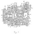
- Figure 1shows one example of a scroll type compressor in accordance with the State of the Art, and including a compressor housing 10 having a front end plate 11 and a cup-shaped casing portion 12 which is attached to an end surface of the end plate 11.
- a hole 11is formed in the centre of the front end plate 11 for penetration of a drive shaft 13.
- An outer peripheral surface of the projection 112extends into the peripheral wall of the cup shaped portion 12.
- An opening 121 of the portion 12is covered by the front end plate 11.
- An 0-ring 14is placed between the outer peripheral surface of the annular projection 112 and the inner wall surface of the portion 12 to seal the mating surfaces of the plate 11 and portion 12.
- An annular sleeve 16projects from the front end surface of the front end plate 11 and surrounds the drive shaft 13 and defines a shaft seal cavity.
- the sleeve 16is formed separately from the front end plate 11, and is fixed to the front end surface of the front end plate 11 by screws (not shown).
- the sleeve 15may be formed integrally with the front end plate 11.
- the drive shaft 13is rotatably supported by the sleeve 16 through a bearing 17 located within the front end of the sleeve 16.
- the drive shaft 13has a disk-shaped rotor 131 at its inner end which is rotatably supported by the front end plate 11 through a bearing 15 located within the hole 111 in the front end plate 11.
- a shaft seal assembly 18is coupled to the drive shaft 13 within the shaft seal cavity of the sleeve 16.
- a pulley 201is rotatably supported by a ball bearing 19 which is carried on the outer surface of the sleeve 16.
- An electromagnetic coil 202is fixed about the outer surface of the sleeve 16 by a support plate.
- An armature plate 203is elastically supported on the outer end of the drive shaft 13.
- the pulley 201, magnetic coil 202 and armature plate 203form a magnetic clutch 20.
- the drive shaft 13is driven by an external power source, for example the engine of an automobile, through a rotation transmitting device, in this case the above described magnetic clutch.
- a fixed scroll 21, an orbiting scroll 22, a driving mechanism for the orbiting scroll 22 and a rotation preventing/thrust bearing mechanism 24 for the orbiting scroll 22are disposed in the interior of the housing 10.
- the fixed scroll 21includes a circular end plate 211 and a spiral element 212 fixed to and extending from one end surface of the circular end plate 211.
- the fixed scroll 121is fixed within the inner chamber of the cup shaped portion 12 by screws 25 screwed into the end plate 211 from outside of the portion 12.
- the end plate 211 of the fixed scroll 21partitions the interior of the cup shaped portion 12 into two chambers, a front chamber 27 and a rear chamber 28.
- the spiral element 212is located within the front chamber 27.
- a partition wall 122projects axially from the inner end surface of the cup shaped portion 12. The end surface of the partition wall 122 contacts the end surface of the circular end plate 211. Thus, the partition wall 122 divides the rear chamber 28 into a discharge chamber 281 formed at a centre portion of the rear chamber 28 and an intermediate chamber 282.
- a gasket 26may be disposed between the end surface of the partition wall 122 and the end plate 211 to secure the sealing.
- the orbiting scroll 22which is located in the front chamber 27, includes a spiral element 222 fixed to and extending from one end surface of the circular end plate 221.
- the spiral element 222 of the orbiting scroll 22 and the spiral element 212 of the fixed scroll 21interfit at an angular offset of 180" and a predetermined radial offset. Sealed pockets are thus formed between the spiral elements 212 and 222.
- the orbiting scroll 22is rotatably supported by a bushing 23, which is connected with the inner end of the disc-shaped portion 131 eccentrically to the axis the drive shaft 13, through a radial needle bearing 30.
- the rotation preventing/thrust bearing mechanism 24includes a fixed ring 241, a fixed race 242, an orbiting ring 243, an orbiting race 244 and balls 245.
- the fixed ring 241is attached on the inner end surface of the front end plate 11 through the fixed race 242 and has a plurality of circular holes 241 a.
- the orbiting ring 243is attached on the rear end surface of the orbiting scroll 22 through the orbiting race 244 and has a plurality of circular holes 243a.
- Each ball 245lies in and between a hole 241 a of the fixed ring 242 and a circular hole 243a of the orbiting ring 243, and rolls along the edges of both circular holes 241 a, 243a. Also, an axial thrust load from the orbiting scroll 22 is supported on the front end plate 11 through the balls 245.
- the compressor housing 10is provided with an inlet port 31 and an outlet port 32 for connecting the compressor to, for example, an external refrigeration circuit.
- Refrigerant gas from the external circuitis introduced into a suction chamber 271 through the inlet port 31 and into the sealed pockets between the spiral elements 212 and 222.
- a pair of holes 214, 215are formed in the end plate 211 of the fixed scroll 21 and are symmetrical positioned so that an axial end surface of the spiral element 222 of the orbiting scroll 22 simultaneously crosses over the holes 214, 215.
- the holes 214, 215communicate between the sealed space and the intermediate pressure chamber 282.
- the hole 214is at a position defined by involute angle 0 1 and opens along the inner side wall of the spiral element 212.
- the other hole 215is placed at a position defined by involute angle (0 1 - n) and opens along the outer side wall of the spiral element 212.
- a control devicesuch as a valve member 34 having valve plates 341, 342 is attached by fasteners 351, 352 to the end surface of the end plate 211 to oppose the holes 214, 215.
- Each valve plate 341, 342is made of a springy material so that the inherent spring of each valve plate 341, 342 pushes it against the opening of the respective hole 214, 215 to close each hole.
- the end plate 211 of the fixed scroll 21has also a communication hole 29 at the outer side portion of the terminal end of the spiral element 212.
- the hole 29connects the front chamber 27 and the intermediate pressure chamber 282 via a communication chamber 283.
- a control mechanism 36which controls communication between the communication chamber 283 and the intermediate pressure chamber 282, includes a cylinder 361, an I-sectioned piston 362 slidably disposed within the cylinder 361 and a coil spring 363 disposed between the lower end portion 362b of the piston 362 and the bottom of the cylinder 361 to support the piston 362.
- a first opening 361 ais formed in a side of the cylinder 362 to connected with the communication chamber 283, and a second hole 361 b is formed in a bottom of the cylinder 361 to connect with the intermediate pressure chamber 282.
- the upper portion of the cylinder 361is covered by a plate 365 provided with an aperture 366 at its centre portion and connected with the discharge chamber 281 via a capillary tube 368.
- the communication between the cylinder 361 and the discharge chamber 281is controlled in this case, by a magnetic valve 364 disposed on the housing 10.
- a piston ring 362cis provided on an upper portion of the piston 362 to prevent leakage of high pressure gas between the cylinder 361 and piston 362.
- Figure 3shows an example of a control mechanism.
- the magnetic valve 364is replaced by a bellows valve element 39, which includes a bellows portion 391 disposed in a first operating chamber 393 and a needle portion 392 attached to the bottom of the bellows portion 391.
- the first operating chamber 393is connected to the communication chamber 283 via a connecting duct 397.
- the needle portion 392slidably penetrates an aperture 398 and extends into a second operating chamber 394.
- the aperture 398interconnects the first and second operating chambers 393, 394 and the second operating chamber 394 is connected to the cylinder 361 and discharge chamber 281 through the capillary tube 368.
- a ball 395is disposed on the top end of a spring 396, which is disposed in the second operating chamber 394 and contacts the end of the needle portion 392.
- the ball 395will control the opening and closing of the aperture 398 owing to the recoil strength of the spring 396 and the operation of the bellows portion 391.
- Figure 4shows another example of a control mechanism which includes a cylinder 401, a piston valve 402, a bellows 403 and a spring 404.
- the piston valve 402is slidably disposed within the cylinder and has openings 402a and 402b. Also, the piston 402 is pushed upwardly by a spring 404 disposed between the bottom portion of the cylinder 401 and the lower end surface of the piston 402.
- the bellows 403is disposed within the interior of the piston valve 402, and includes a valve portion 403a and a bellows portion 403b.
- the valve portion 403ais extended to the outside of the piston valve 402 through opening 402a which is formed at the upper end of the piston 402.
- the cylinder 401is connected with the discharge chamber 281 through conduits 368, 405, in which an orifice 406 is disposed.
- the valve portion 403aopens the opening 402a of the piston valve 402, and therefore, a small amount of compressed gas which is supplied to the top space of the cylinder 401 from the orifice 406 flows into the communication chamber 283 through the piston 402 and cylinder 401.
- the piston 403, which is placed to close the opening 361 bis pushed upwardly by the recoil strength of the spring 404, and accomplish communication between the communication chamber 263 and the intermediate pressure chamber 282. Therefore, the compression ratio is decreased.
- valve portion 403ais drawn down owing to operation of the bellows 403b, the opening 402a is closed by the valve portion 403a.
- a small amount of compressed gasalways flows from the discharge chamber 281 into the top space of the cylinder 401, and the piston valve 402 is pushed downwardly against the recoil strength of the spring 404.
- the openings 361 (a, b),are thus closed by the piston valve 402, and the compression ratio is increased.
- a needle-ball type valve mechanism 41may be used, as shown in Figure 5.
- the strength of the pushing force by the bellowswill be controlled by positioning of the bellows 403b.
- the position of the bellows 403bwill be determined by a screw 42 at the bottom of the piston valve 402, also as shown in Figure 5.
Landscapes
- Engineering & Computer Science (AREA)
- Mechanical Engineering (AREA)
- General Engineering & Computer Science (AREA)
- Rotary Pumps (AREA)
- Applications Or Details Of Rotary Compressors (AREA)
Description
- The present invention relates to a scroll type compressor, with a variable displacement mechanism.
- When the air conditioning load in the compartment of a car is decreased by an air conditioning system, or the temperature in the compartment of the car is below the predetermined temperature, the displacement of the system compressor need not necessarily be as high as under normal load. Accordingly, the compression ratio of the compressor can be decreased.
- Conventionally, a scroll type compressor, in which the compression ratio can be changed, is known. For example, US-A-4 505 651 and EP-A-0 144 169 show a variable displacement mechanism.
- However, in US-A-4 505 651, the change in compression ratio is insufficient. Also, in the mechanism shown in EP-A-0 144 169, the temperature of discharge gas which is discharged from the compressor is abnormally increased when operating at high speed.
- It is primary object of the present invention to provide a scroll type compressor with a variable displacement mechanism which can change compression volume in accordance with the load on a compressor, or the variation of the rotational speed of the compressor, whilst avoiding suction pressure loss and an increase in the temperature of discharged gas.
- According to the invention, a scroll type compressor including a housing having an inlet port and an outlet port;
- a fixed scroll fixed within the housing and having a circular end plate from which a first spiral element extends;
- an orbiting scroll having a circular end plate from which a second spiral element extends, the first and second spiral elements interfitting at an angular and radial offset to make a plurality of line contacts to define at least one pair of fluid pockets within the interior of the housing;
- a driving mechanism operatively connected to the orbiting scroll to effect an orbital motion of the orbiting scroll, and thereby change the volumes of the pockets;
- a rotation preventing mechanism for preventing rotation of the orbiting scroll during the orbital motion;
- the end plate of the fixed scroll dividing the interior of the housing into a front chamber and a rear chamber;
- the front chamber being associated with the inlet port and with a suction chamber;
- and the rear chamber being divided into a discharge chamber, which is associated with the outlet port and with a central fluid pocket formed by the scrolls, and an intermediate pressure chamber;
- at least one pair of holes formed through the circular end plate of the fixed scroll to form a fluid channel between the fluid pockets and the intermediate pressure chamber;
- a communication channel formed through the circular end plate of the fixed scroll between the intermediate pressure chamber and the suction chamber;
- and a control mechanism incorporating a valve element associated with the intermediate pressure chamber to control communication between the intermediate pressure chamber and the suction chamber and hence the compression ratio of the compressor;
- the valve element being actuated by the fluid pressure from the discharge chamber;
- and the fluid pressure from the discharge chamber being applied to the valve element against the action of a spring under the control of a control element is characterised in that the control element is a bellows which is responsive to pressure in the suction chamber and modulates the pressure applied to the valve element so that the valve element adopts a position corresponding to the suction pressure, and the communication between the intermediate pressure chamber and the suction chamber and hence the compression ratio are correspondingly set.
- Some examples of a compressor constructed in accordance with the invention are illustrated in the accompanying drawings, in which:
- Figure 1 is a central vertical cross-sectional view of one example of compressor; according to the State of the Art.
- Figure 2 is a diagrammatic sectional view through one end of the Figure 1 compressor; and,
- Figures 3 to 5 are cross-sectional views through three exaples of variable displacement control mechanisms according to the invention.
- Figure 1 shows one example of a scroll type compressor in accordance with the State of the Art, and including a
compressor housing 10 having afront end plate 11 and a cup-shaped casing portion 12 which is attached to an end surface of theend plate 11. Ahole 11 is formed in the centre of thefront end plate 11 for penetration of adrive shaft 13. Anannular projection 112, which is provided on a rear surface of thefront end plate 11, faces the cup shapedcasing 12 and is concentric with thehole 111. An outer peripheral surface of theprojection 112 extends into the peripheral wall of the cup shapedportion 12. Thus, anopening 121 of theportion 12 is covered by thefront end plate 11. An 0-ring 14 is placed between the outer peripheral surface of theannular projection 112 and the inner wall surface of theportion 12 to seal the mating surfaces of theplate 11 andportion 12. - An
annular sleeve 16 projects from the front end surface of thefront end plate 11 and surrounds thedrive shaft 13 and defines a shaft seal cavity. In the example shown in Figure 1, thesleeve 16 is formed separately from thefront end plate 11, and is fixed to the front end surface of thefront end plate 11 by screws (not shown). Alternatively, thesleeve 15 may be formed integrally with thefront end plate 11. - The
drive shaft 13 is rotatably supported by thesleeve 16 through abearing 17 located within the front end of thesleeve 16. Thedrive shaft 13 has a disk-shaped rotor 131 at its inner end which is rotatably supported by thefront end plate 11 through abearing 15 located within thehole 111 in thefront end plate 11. Ashaft seal assembly 18 is coupled to thedrive shaft 13 within the shaft seal cavity of thesleeve 16. - A
pulley 201 is rotatably supported by a ball bearing 19 which is carried on the outer surface of thesleeve 16. Anelectromagnetic coil 202 is fixed about the outer surface of thesleeve 16 by a support plate. Anarmature plate 203 is elastically supported on the outer end of thedrive shaft 13. Thepulley 201,magnetic coil 202 andarmature plate 203 form amagnetic clutch 20. In operation, thedrive shaft 13 is driven by an external power source, for example the engine of an automobile, through a rotation transmitting device, in this case the above described magnetic clutch. - A
fixed scroll 21, anorbiting scroll 22, a driving mechanism for the orbitingscroll 22 and a rotation preventing/thrust bearing mechanism 24 for the orbitingscroll 22 are disposed in the interior of thehousing 10. - The
fixed scroll 21 includes acircular end plate 211 and a spiral element 212 fixed to and extending from one end surface of thecircular end plate 211. Thefixed scroll 121 is fixed within the inner chamber of the cup shapedportion 12 byscrews 25 screwed into theend plate 211 from outside of theportion 12. Theend plate 211 of thefixed scroll 21 partitions the interior of the cup shapedportion 12 into two chambers, afront chamber 27 and arear chamber 28. The spiral element 212 is located within thefront chamber 27. - A
partition wall 122 projects axially from the inner end surface of the cup shapedportion 12. The end surface of thepartition wall 122 contacts the end surface of thecircular end plate 211. Thus, thepartition wall 122 divides therear chamber 28 into adischarge chamber 281 formed at a centre portion of therear chamber 28 and anintermediate chamber 282. Agasket 26 may be disposed between the end surface of thepartition wall 122 and theend plate 211 to secure the sealing. - The
orbiting scroll 22, which is located in thefront chamber 27, includes a spiral element 222 fixed to and extending from one end surface of thecircular end plate 221. The spiral element 222 of theorbiting scroll 22 and the spiral element 212 of thefixed scroll 21 interfit at an angular offset of 180" and a predetermined radial offset. Sealed pockets are thus formed between the spiral elements 212 and 222. The orbitingscroll 22 is rotatably supported by abushing 23, which is connected with the inner end of the disc-shaped portion 131 eccentrically to the axis thedrive shaft 13, through a radial needle bearing 30. - While the orbiting scroll 22 orbits, the rotation of the orbiting
scroll 22 is prevented by a rotation preventing/thrust bearing mechanism 24, which is located between the inner end surface of thefront end plate 11 and thecircular end plate 221 of theorbiting scroll 22. The rotation preventing/thrust bearing mechanism 24 includes afixed ring 241, afixed race 242, an orbitingring 243, an orbiting race 244 andballs 245. Thefixed ring 241 is attached on the inner end surface of thefront end plate 11 through thefixed race 242 and has a plurality of circular holes 241 a. The orbitingring 243 is attached on the rear end surface of the orbitingscroll 22 through the orbiting race 244 and has a plurality of circular holes 243a. Eachball 245 lies in and between a hole 241 a of thefixed ring 242 and a circular hole 243a of theorbiting ring 243, and rolls along the edges of both circular holes 241 a, 243a. Also, an axial thrust load from the orbitingscroll 22 is supported on thefront end plate 11 through theballs 245. - The
compressor housing 10 is provided with aninlet port 31 and anoutlet port 32 for connecting the compressor to, for example, an external refrigeration circuit. Refrigerant gas from the external circuit is introduced into a suction chamber 271 through theinlet port 31 and into the sealed pockets between the spiral elements 212 and 222. Openings, formed by the ourer terminal end of one spiral element and the outer side surface of the other spiral element, sequentially open and close during the orbital motion of the orbitingscroll 22. When the openings are open, fluid to be compressed flows into the pockets but no compression occurs. When the opening are closed, thereby sealing off the pockets, no additional fluid flows into the pockets and compression begins. Since the location of the outer terminal ends of the spiral elements 212 and 222 is at the final involute angle, location of the openings is directly related to the final involute angle. Furthermore, refrigerant gas in the sealed spaced is moved radially inwardly and compressed by the orbital motion of the orbitingscroll 22. Compressed refrigerant gas at the centre sealed space is discharged to thedischarge chamber 281 through adischarge port 213, which is formed at the centre of theend plate 211. - Referring to Figures 1 and 2, a pair of
holes end plate 211 of the fixedscroll 21 and are symmetrical positioned so that an axial end surface of the spiral element 222 of the orbitingscroll 22 simultaneously crosses over theholes holes intermediate pressure chamber 282. Thehole 214 is at a position defined by involute angle 01 and opens along the inner side wall of the spiral element 212. Theother hole 215 is placed at a position defined by involute angle (01- n) and opens along the outer side wall of the spiral element 212. A control device, such as a valve member 34 havingvalve plates 341, 342 is attached byfasteners 351, 352 to the end surface of theend plate 211 to oppose theholes valve plate 341, 342 is made of a springy material so that the inherent spring of eachvalve plate 341, 342 pushes it against the opening of therespective hole - The
end plate 211 of the fixedscroll 21 has also acommunication hole 29 at the outer side portion of the terminal end of the spiral element 212. Thehole 29 connects thefront chamber 27 and theintermediate pressure chamber 282 via acommunication chamber 283. A control mechanism 36, which controls communication between thecommunication chamber 283 and theintermediate pressure chamber 282, includes acylinder 361, an I-sectionedpiston 362 slidably disposed within thecylinder 361 and acoil spring 363 disposed between the lower end portion 362b of thepiston 362 and the bottom of thecylinder 361 to support thepiston 362. A first opening 361 a is formed in a side of thecylinder 362 to connected with thecommunication chamber 283, and a second hole 361 b is formed in a bottom of thecylinder 361 to connect with theintermediate pressure chamber 282. The upper portion of thecylinder 361 is covered by aplate 365 provided with an aperture 366 at its centre portion and connected with thedischarge chamber 281 via acapillary tube 368. The communication between thecylinder 361 and thedischarge chamber 281 is controlled in this case, by amagnetic valve 364 disposed on thehousing 10. A piston ring 362c is provided on an upper portion of thepiston 362 to prevent leakage of high pressure gas between thecylinder 361 andpiston 362. - The operation of the control mechanism 36 will now be described. When the orbiting
scroll 22 is operated by rotation of the drivingshaft 13, refrigerant gas, which flows into the suction chamber 271 through theinlet port 31, is taken into the sealed spaces defined between the spiral elements 212 and 222. The refrigerant gas in the sealed spaces moves toward the centres of the spiral elements 212 and 222 with a resultant volume reduction and compression, and is discharged via from thedischarge port 213 into thedischarge chamber 281. - In this condition, if the
electromagnetic valve 364 is deenergized, communication between thedischarge chamber 281 and thecylinder 361 is prevented. Thus, thepiston 362 is urged upwardly by the recoil strength of thespring 363 until the lower end portion 362b of the piston is above the opening 361 a. As a result, theintermediate pressure chamber 282 is connected with thecommunication chamber 283 through thecylinder 361. Therefore, theintermediate pressure chamber 282 is maintained at the suction pressure level, whereby refrigerant gas in the fluid pockets flows into theintermediate pressure chamber 282 through theholes front chamber 27. The compression stroke of the compressor is started after these holes are closed by the spiral element 222. Thus, the compression ratio of the compressor is greatly reduced by operation of the control mechanism 36. - On the other hand, when the
electromagnetic valve 364 is energized, compressed gas in thedischarge chamber 281 flows into thecylinder 361 through thecapillary tube 368. At that time, as the recoil strength of thespring 363 is selected to be less than the pressure force on the piston of the compressed gas, thepiston 362 will be pushed downwardly by the compressed gas. In this situation, the hole 361 a, is covered by thepiston 362 and communication between thecommunication chamber 283 and theintermediate pressure chamber 282 is prevented. Therefore, the pressure in theintermediate pressure chamber 282 is gradually increased owing to gas leakage from the fluid pockets through theholes intermediate pressure chamber 282 is equal to the pressure in the fluid pockets. When pressure equalization occurs, theholes valve plates 341, 342 so that compression operates normally and the displacement volume when the fluid pockets are sealed off is the same as the displacement volume when the terminal end of each respective spiral element 212, 222 first contacts the outer peripheral surfaces of thespiral elements - Figure 3 shows an example of a control mechanism. The
magnetic valve 364 is replaced by abellows valve element 39, which includes abellows portion 391 disposed in a first operating chamber 393 and aneedle portion 392 attached to the bottom of thebellows portion 391. The first operating chamber 393 is connected to thecommunication chamber 283 via a connecting duct 397. Theneedle portion 392 slidably penetrates anaperture 398 and extends into asecond operating chamber 394. Theaperture 398 interconnects the first andsecond operating chambers 393, 394 and thesecond operating chamber 394 is connected to thecylinder 361 anddischarge chamber 281 through thecapillary tube 368. Aball 395 is disposed on the top end of aspring 396, which is disposed in thesecond operating chamber 394 and contacts the end of theneedle portion 392. Thus, theball 395 will control the opening and closing of theaperture 398 owing to the recoil strength of thespring 396 and the operation of thebellows portion 391. - During operation of the compressor 1, a small amount of compressed gas which is discharged from
discharge chamber 281 is, via the orifice 381, always supplied to thesecond operating chamber 394. When the gas pressure in the first operating chamber 393 is larger than that in thebellow portion 391, thebellows portion 391 shrinks. Theball 395 is thus moved up by the recoil strength of thespring 396 together with theneedle portion 392 and closes the opening of theaperture 398 connected between the first operating chamber 393 and thesecond operating chamber 394. Thepiston 362 is pushed downwardly against the recoil strength of thespring 363 by compressed gas pressure and closes the opening 361 b. Thecommunication chamber 283 is disconnected fromintermediate pressure chamber 282. Therefore, the compression volume is increased. When the gas pressure in the first operating chamber 393 is decreased until the gas pressure in thebellows portion 391 is larger than the gas pressure in the first operating chamber 393, the gas in thebellows portion 391 expands. Theneedle portion 392 moves down and pushes theball 395 downwardly against the recoil strength of thespring 395. Compressed gas in thesecond operating chamber 394 flows into the first operating chamber 393 through theaperture 398. Since the pressure in thesecond operating chamber 394 is decreased, thepiston 362 is moved up by the elastic force of thespring 363. Accordingly, thecommunication chamber 283 is connected with theintermediate pressure chamber 282 through thecylinder 361 and holes 361 a and 361 b. Therefore, the compression volume is decreased. - Figure 4 shows another example of a control mechanism which includes a
cylinder 401, apiston valve 402, abellows 403 and aspring 404. - The
piston valve 402 is slidably disposed within the cylinder and hasopenings 402a and 402b. Also, thepiston 402 is pushed upwardly by aspring 404 disposed between the bottom portion of thecylinder 401 and the lower end surface of thepiston 402. The bellows 403 is disposed within the interior of thepiston valve 402, and includes a valve portion 403a and a bellows portion 403b. The valve portion 403a is extended to the outside of thepiston valve 402 through opening 402a which is formed at the upper end of thepiston 402. Thecylinder 401 is connected with thedischarge chamber 281 throughconduits orifice 406 is disposed. - Since the interior of the
piston valve 402 is connected with thecommunication chamber 283 through theopening 402b, thecylinder 401 and the opening 361a, if the gas pressure in thecommunication chamber 283 is decreased to less than the pressure of the gas enclosed in the bellows 403b, the bellows 403b is extended. In this situation, the valve portion 403a opens the opening 402a of thepiston valve 402, and therefore, a small amount of compressed gas which is supplied to the top space of thecylinder 401 from theorifice 406 flows into thecommunication chamber 283 through thepiston 402 andcylinder 401. At this time, thepiston 403, which is placed to close the opening 361 b, is pushed upwardly by the recoil strength of thespring 404, and accomplish communication between the communication chamber 263 and theintermediate pressure chamber 282. Therefore, the compression ratio is decreased. - On the other hand, if the pressure of gas in the
communication chamber 283 is increased and becomes larger than the pressure of gas in the bellows 403b, the bellows shrinks. Since the valve portion 403a is drawn down owing to operation of the bellows 403b, the opening 402a is closed by the valve portion 403a. In this situation, a small amount of compressed gas always flows from thedischarge chamber 281 into the top space of thecylinder 401, and thepiston valve 402 is pushed downwardly against the recoil strength of thespring 404. The openings 361 (a, b), are thus closed by thepiston valve 402, and the compression ratio is increased. This construction of the valve portion 403a is a simple structure. However, a needle-balltype valve mechanism 41 may be used, as shown in Figure 5. Also, the strength of the pushing force by the bellows will be controlled by positioning of the bellows 403b. The position of the bellows 403b will be determined by ascrew 42 at the bottom of thepiston valve 402, also as shown in Figure 5.
Claims (3)
characterised in that the control element is a bellows (391, 403b) which is responsive to pressure in the suction chamber and modulates the pressure applied to the valve element so that the valve element adopts a position corresponding to the suction pressure, and the communication between the intermediate pressure chamber (282) and the suction chamber (271) and hence the compression ratio are correspondingly set.
Applications Claiming Priority (2)
| Application Number | Priority Date | Filing Date | Title |
|---|---|---|---|
| JP60132487AJPH0641756B2 (en) | 1985-06-18 | 1985-06-18 | Variable capacity scroll type compressor |
| JP132487/85 | 1985-06-18 |
Publications (2)
| Publication Number | Publication Date |
|---|---|
| EP0206759A1 EP0206759A1 (en) | 1986-12-30 |
| EP0206759B1true EP0206759B1 (en) | 1989-05-10 |
Family
ID=15082520
Family Applications (1)
| Application Number | Title | Priority Date | Filing Date |
|---|---|---|---|
| EP86304704AExpiredEP0206759B1 (en) | 1985-06-18 | 1986-06-18 | Scroll type compressor |
Country Status (9)
| Country | Link |
|---|---|
| US (2) | US4744733A (en) |
| EP (1) | EP0206759B1 (en) |
| JP (1) | JPH0641756B2 (en) |
| KR (1) | KR930004660B1 (en) |
| CN (1) | CN1025449C (en) |
| AU (1) | AU599033B2 (en) |
| BR (1) | BR8602825A (en) |
| DE (1) | DE3663282D1 (en) |
| IN (1) | IN166856B (en) |
Families Citing this family (84)
| Publication number | Priority date | Publication date | Assignee | Title |
|---|---|---|---|---|
| DE3674966D1 (en) | 1985-08-10 | 1990-11-22 | Sanden Corp | SPIRAL COMPRESSOR WITH DEVICE CONTROL DEVICE. |
| JPS63212789A (en)* | 1987-02-28 | 1988-09-05 | Sanden Corp | Variable capacity type scroll compressor |
| JPH0744775Y2 (en)* | 1987-03-26 | 1995-10-11 | 三菱重工業株式会社 | Compressor capacity control device |
| JPH0615872B2 (en)* | 1987-06-30 | 1994-03-02 | サンデン株式会社 | Variable capacity scroll compressor |
| JPH0746787Y2 (en)* | 1987-12-08 | 1995-10-25 | サンデン株式会社 | Variable capacity scroll compressor |
| US4840545A (en)* | 1988-05-16 | 1989-06-20 | American Standard Inc. | Scroll compressor relief valve |
| JPH0219677A (en)* | 1988-07-08 | 1990-01-23 | Sanden Corp | Scroll type fluid compressor |
| JPH0245685A (en)* | 1988-08-03 | 1990-02-15 | Daikin Ind Ltd | Oil supply mechanism for horizontal open compressor |
| JPH02230995A (en)* | 1989-03-02 | 1990-09-13 | Mitsubishi Heavy Ind Ltd | Compressor for heat pump and operating method thereof |
| JPH0772543B2 (en)* | 1989-08-31 | 1995-08-02 | ダイキン工業株式会社 | Scroll compressor |
| JP2780233B2 (en)* | 1989-10-30 | 1998-07-30 | ダイキン工業株式会社 | Scroll compressor |
| JP2553033Y2 (en)* | 1989-12-08 | 1997-11-05 | 株式会社豊田自動織機製作所 | Variable capacity scroll compressor |
| JPH0392580U (en)* | 1990-01-11 | 1991-09-20 | ||
| JPH03116789U (en)* | 1990-03-15 | 1991-12-03 | ||
| US5141407A (en)* | 1990-10-01 | 1992-08-25 | Copeland Corporation | Scroll machine with overheating protection |
| JP2972370B2 (en)* | 1991-03-15 | 1999-11-08 | サンデン株式会社 | Variable capacity scroll compressor |
| JP3100452B2 (en)* | 1992-02-18 | 2000-10-16 | サンデン株式会社 | Variable capacity scroll compressor |
| US5451146A (en)* | 1992-04-01 | 1995-09-19 | Nippondenso Co., Ltd. | Scroll-type variable-capacity compressor with bypass valve |
| US5474431A (en)* | 1993-11-16 | 1995-12-12 | Copeland Corporation | Scroll machine having discharge port inserts |
| JP3376692B2 (en)* | 1994-05-30 | 2003-02-10 | 株式会社日本自動車部品総合研究所 | Scroll compressor |
| JP3376729B2 (en)* | 1994-06-08 | 2003-02-10 | 株式会社日本自動車部品総合研究所 | Scroll compressor |
| JPH08151991A (en)* | 1994-11-29 | 1996-06-11 | Sanden Corp | Variable displacement scroll compressor |
| US5613841A (en)* | 1995-06-07 | 1997-03-25 | Copeland Corporation | Capacity modulated scroll machine |
| US6047557A (en)* | 1995-06-07 | 2000-04-11 | Copeland Corporation | Adaptive control for a refrigeration system using pulse width modulated duty cycle scroll compressor |
| US5741120A (en) | 1995-06-07 | 1998-04-21 | Copeland Corporation | Capacity modulated scroll machine |
| JP3549631B2 (en)* | 1995-06-26 | 2004-08-04 | サンデン株式会社 | Variable capacity scroll compressor |
| US5707210A (en)* | 1995-10-13 | 1998-01-13 | Copeland Corporation | Scroll machine with overheating protection |
| JP3723283B2 (en)* | 1996-06-25 | 2005-12-07 | サンデン株式会社 | Scroll type variable capacity compressor |
| JP3585150B2 (en)* | 1997-01-21 | 2004-11-04 | 株式会社豊田自動織機 | Control valve for variable displacement compressor |
| US6206652B1 (en) | 1998-08-25 | 2001-03-27 | Copeland Corporation | Compressor capacity modulation |
| JPH11210650A (en) | 1998-01-28 | 1999-08-03 | Sanden Corp | Scroll type compressor |
| US6079952A (en)* | 1998-02-02 | 2000-06-27 | Ford Global Technologies, Inc. | Continuous capacity control for a multi-stage compressor |
| US6089830A (en)* | 1998-02-02 | 2000-07-18 | Ford Global Technologies, Inc. | Multi-stage compressor with continuous capacity control |
| US6478550B2 (en)* | 1998-06-12 | 2002-11-12 | Daikin Industries, Ltd. | Multi-stage capacity-controlled scroll compressor |
| JP2000257569A (en) | 1999-03-04 | 2000-09-19 | Sanden Corp | Scroll compressor |
| US6505475B1 (en) | 1999-08-20 | 2003-01-14 | Hudson Technologies Inc. | Method and apparatus for measuring and improving efficiency in refrigeration systems |
| JP3556898B2 (en)* | 2000-11-16 | 2004-08-25 | 三菱重工業株式会社 | Compressor |
| US6663358B2 (en) | 2001-06-11 | 2003-12-16 | Bristol Compressors, Inc. | Compressors for providing automatic capacity modulation and heat exchanging system including the same |
| JP4070740B2 (en)* | 2004-03-31 | 2008-04-02 | 株式会社デンソー | Switching valve structure for fluid machinery |
| US7771178B2 (en)* | 2006-12-22 | 2010-08-10 | Emerson Climate Technologies, Inc. | Vapor injection system for a scroll compressor |
| US8157538B2 (en) | 2007-07-23 | 2012-04-17 | Emerson Climate Technologies, Inc. | Capacity modulation system for compressor and method |
| JP5291317B2 (en)* | 2007-09-28 | 2013-09-18 | 日立オートモティブシステムズ株式会社 | Scroll type fluid machine and air suspension device using the same |
| KR100916229B1 (en)* | 2008-01-31 | 2009-09-08 | 엘지전자 주식회사 | Mode changer of scroll compressor |
| WO2009155104A2 (en)* | 2008-05-30 | 2009-12-23 | Emerson Climate Technologies, Inc. | Compressor having capacity modulation system |
| CN102089523B (en) | 2008-05-30 | 2014-01-08 | 艾默生环境优化技术有限公司 | Compressor with capacity adjustment system |
| CN102076963B (en)* | 2008-05-30 | 2013-09-18 | 艾默生环境优化技术有限公司 | A compressor with capacity adjustment system |
| CN102089524B (en)* | 2008-05-30 | 2014-09-03 | 艾默生环境优化技术有限公司 | Compressor with capacity adjustment system |
| US7972125B2 (en)* | 2008-05-30 | 2011-07-05 | Emerson Climate Technologies, Inc. | Compressor having output adjustment assembly including piston actuation |
| US7976296B2 (en)* | 2008-12-03 | 2011-07-12 | Emerson Climate Technologies, Inc. | Scroll compressor having capacity modulation system |
| BRPI1007407A2 (en) | 2009-01-27 | 2016-02-16 | Emerson Climate Technologies | unloading system and method for a compressor |
| US7988433B2 (en) | 2009-04-07 | 2011-08-02 | Emerson Climate Technologies, Inc. | Compressor having capacity modulation assembly |
| US8616014B2 (en)* | 2009-05-29 | 2013-12-31 | Emerson Climate Technologies, Inc. | Compressor having capacity modulation or fluid injection systems |
| US8568118B2 (en)* | 2009-05-29 | 2013-10-29 | Emerson Climate Technologies, Inc. | Compressor having piston assembly |
| TW201120316A (en)* | 2009-12-04 | 2011-06-16 | Ind Tech Res Inst | Self-sealing scroll compressor |
| US8517703B2 (en)* | 2010-02-23 | 2013-08-27 | Emerson Climate Technologies, Inc. | Compressor including valve assembly |
| CN102865228B (en)* | 2012-09-06 | 2015-09-30 | 安徽东升机电有限责任公司 | Heat pump type air conditioner compressor of electric automobile |
| US9249802B2 (en) | 2012-11-15 | 2016-02-02 | Emerson Climate Technologies, Inc. | Compressor |
| US9651043B2 (en) | 2012-11-15 | 2017-05-16 | Emerson Climate Technologies, Inc. | Compressor valve system and assembly |
| US9127677B2 (en) | 2012-11-30 | 2015-09-08 | Emerson Climate Technologies, Inc. | Compressor with capacity modulation and variable volume ratio |
| US9435340B2 (en) | 2012-11-30 | 2016-09-06 | Emerson Climate Technologies, Inc. | Scroll compressor with variable volume ratio port in orbiting scroll |
| CN103233896B (en)* | 2013-05-15 | 2015-10-28 | 力达(中国)机电有限公司 | A kind of scroll type air compressor |
| JP6387613B2 (en)* | 2014-01-08 | 2018-09-12 | 株式会社豊田自動織機 | Electric compressor |
| US9739277B2 (en) | 2014-05-15 | 2017-08-22 | Emerson Climate Technologies, Inc. | Capacity-modulated scroll compressor |
| US9989057B2 (en) | 2014-06-03 | 2018-06-05 | Emerson Climate Technologies, Inc. | Variable volume ratio scroll compressor |
| KR101873417B1 (en)* | 2014-12-16 | 2018-07-31 | 엘지전자 주식회사 | Scroll compressor |
| US9790940B2 (en) | 2015-03-19 | 2017-10-17 | Emerson Climate Technologies, Inc. | Variable volume ratio compressor |
| US10598180B2 (en) | 2015-07-01 | 2020-03-24 | Emerson Climate Technologies, Inc. | Compressor with thermally-responsive injector |
| US10378540B2 (en) | 2015-07-01 | 2019-08-13 | Emerson Climate Technologies, Inc. | Compressor with thermally-responsive modulation system |
| CN207377799U (en) | 2015-10-29 | 2018-05-18 | 艾默生环境优化技术有限公司 | Compressor |
| US10801495B2 (en) | 2016-09-08 | 2020-10-13 | Emerson Climate Technologies, Inc. | Oil flow through the bearings of a scroll compressor |
| US10890186B2 (en) | 2016-09-08 | 2021-01-12 | Emerson Climate Technologies, Inc. | Compressor |
| US10753352B2 (en) | 2017-02-07 | 2020-08-25 | Emerson Climate Technologies, Inc. | Compressor discharge valve assembly |
| CN107165824A (en)* | 2017-04-26 | 2017-09-15 | 合肥江航飞机装备有限公司 | A kind of car air-conditioner vortex positive displacement compressor core controls ripple component |
| US11022119B2 (en) | 2017-10-03 | 2021-06-01 | Emerson Climate Technologies, Inc. | Variable volume ratio compressor |
| US10962008B2 (en) | 2017-12-15 | 2021-03-30 | Emerson Climate Technologies, Inc. | Variable volume ratio compressor |
| US10995753B2 (en) | 2018-05-17 | 2021-05-04 | Emerson Climate Technologies, Inc. | Compressor having capacity modulation assembly |
| US11656003B2 (en) | 2019-03-11 | 2023-05-23 | Emerson Climate Technologies, Inc. | Climate-control system having valve assembly |
| US11655813B2 (en) | 2021-07-29 | 2023-05-23 | Emerson Climate Technologies, Inc. | Compressor modulation system with multi-way valve |
| US12259163B2 (en) | 2022-06-01 | 2025-03-25 | Copeland Lp | Climate-control system with thermal storage |
| US11846287B1 (en) | 2022-08-11 | 2023-12-19 | Copeland Lp | Scroll compressor with center hub |
| US11965507B1 (en) | 2022-12-15 | 2024-04-23 | Copeland Lp | Compressor and valve assembly |
| US12416308B2 (en) | 2022-12-28 | 2025-09-16 | Copeland Lp | Compressor with shutdown assembly |
| US12173708B1 (en) | 2023-12-07 | 2024-12-24 | Copeland Lp | Heat pump systems with capacity modulation |
| US12163523B1 (en) | 2023-12-15 | 2024-12-10 | Copeland Lp | Compressor and valve assembly |
Family Cites Families (7)
| Publication number | Priority date | Publication date | Assignee | Title |
|---|---|---|---|---|
| US3759057A (en)* | 1972-01-10 | 1973-09-18 | Westinghouse Electric Corp | Room air conditioner having compressor with variable capacity and control therefor |
| US4459817A (en)* | 1980-12-16 | 1984-07-17 | Nippon Soken, Inc. | Rotary compressor |
| JPS57148089A (en)* | 1981-03-09 | 1982-09-13 | Sanden Corp | Scroll type compressor |
| JPS58155287A (en)* | 1982-03-09 | 1983-09-14 | Nippon Soken Inc | Refrigerating unit |
| JPS5928083A (en)* | 1982-08-07 | 1984-02-14 | Sanden Corp | Scroll type compressor |
| JPS60101295A (en)* | 1983-11-08 | 1985-06-05 | Sanden Corp | Compression capacity varying type scroll compressor |
| GB2166801B (en)* | 1984-11-09 | 1988-04-07 | Sanden Corp | A scroll-type rotary fluid-compressor |
- 1985
- 1985-06-18JPJP60132487Apatent/JPH0641756B2/ennot_activeExpired - Fee Related
- 1986
- 1986-06-18AUAU58830/86Apatent/AU599033B2/ennot_activeExpired
- 1986-06-18DEDE8686304704Tpatent/DE3663282D1/ennot_activeExpired
- 1986-06-18BRBR8602825Apatent/BR8602825A/ennot_activeIP Right Cessation
- 1986-06-18KRKR1019860004833Apatent/KR930004660B1/ennot_activeExpired - Lifetime
- 1986-06-18EPEP86304704Apatent/EP0206759B1/ennot_activeExpired
- 1986-06-18USUS06/875,561patent/US4744733A/ennot_activeCeased
- 1986-06-18CNCN86105602Apatent/CN1025449C/ennot_activeExpired - Lifetime
- 1986-06-30ININ566/DEL/86Apatent/IN166856B/enunknown
- 1990
- 1990-05-10USUS07/522,058patent/USRE34148E/ennot_activeExpired - Lifetime
Also Published As
| Publication number | Publication date |
|---|---|
| USRE34148E (en) | 1992-12-22 |
| JPH0641756B2 (en) | 1994-06-01 |
| KR870000508A (en) | 1987-02-18 |
| KR930004660B1 (en) | 1993-06-02 |
| CN86105602A (en) | 1987-04-01 |
| EP0206759A1 (en) | 1986-12-30 |
| JPS61291792A (en) | 1986-12-22 |
| IN166856B (en) | 1990-07-28 |
| AU5883086A (en) | 1986-12-24 |
| US4744733A (en) | 1988-05-17 |
| BR8602825A (en) | 1987-02-10 |
| DE3663282D1 (en) | 1989-06-15 |
| AU599033B2 (en) | 1990-07-12 |
| CN1025449C (en) | 1994-07-13 |
Similar Documents
| Publication | Publication Date | Title |
|---|---|---|
| EP0206759B1 (en) | Scroll type compressor | |
| EP0373269B1 (en) | Scroll type compressor with variable displacement mechanism | |
| EP0211672B1 (en) | Scroll type compressor with variable displacement mechanism | |
| US4642034A (en) | Scroll type compressor with displacement adjusting mechanism | |
| US4505651A (en) | Scroll type compressor with displacement adjusting mechanism | |
| EP0297840B1 (en) | Scroll type compressor with variable displacement mechanism | |
| US4673340A (en) | Variable capacity scroll type fluid compressor | |
| US4468178A (en) | Scroll type compressor with displacement adjusting mechanism | |
| EP0009350B1 (en) | Scroll-type fluid compressor units | |
| EP0043701B1 (en) | Capacity control for a scroll-type fluid displacement apparatus | |
| US4514150A (en) | Scroll type compressor with displacement adjusting mechanism | |
| US5269661A (en) | Scroll type fluid displacement apparatus having a capacity control mechanism | |
| US4890987A (en) | Scroll type compressor with seal supporting anti-wear plate portions | |
| EP0503629B1 (en) | Scroll type compressor with variable displacement mechanism | |
| EP0754862B1 (en) | A fluid displacement apparatus with variable displacement mechanism | |
| EP0113786A1 (en) | Scroll type compressor with displacement adjusting mechanism | |
| GB2146075A (en) | Scroll type compressor with displacement adjusting mechanism | |
| EP0468238B1 (en) | Scroll type compressor with variable displacement mechanism | |
| JPH0255636B2 (en) |
Legal Events
| Date | Code | Title | Description |
|---|---|---|---|
| PUAI | Public reference made under article 153(3) epc to a published international application that has entered the european phase | Free format text:ORIGINAL CODE: 0009012 | |
| AK | Designated contracting states | Kind code of ref document:A1 Designated state(s):DE FR GB IT SE | |
| 17P | Request for examination filed | Effective date:19870320 | |
| 17Q | First examination report despatched | Effective date:19880606 | |
| GRAA | (expected) grant | Free format text:ORIGINAL CODE: 0009210 | |
| AK | Designated contracting states | Kind code of ref document:B1 Designated state(s):DE FR GB IT SE | |
| ITF | It: translation for a ep patent filed | ||
| REF | Corresponds to: | Ref document number:3663282 Country of ref document:DE Date of ref document:19890615 | |
| ET | Fr: translation filed | ||
| PLBE | No opposition filed within time limit | Free format text:ORIGINAL CODE: 0009261 | |
| STAA | Information on the status of an ep patent application or granted ep patent | Free format text:STATUS: NO OPPOSITION FILED WITHIN TIME LIMIT | |
| 26N | No opposition filed | ||
| ITTA | It: last paid annual fee | ||
| EAL | Se: european patent in force in sweden | Ref document number:86304704.9 | |
| REG | Reference to a national code | Ref country code:GB Ref legal event code:IF02 | |
| PGFP | Annual fee paid to national office [announced via postgrant information from national office to epo] | Ref country code:SE Payment date:20050607 Year of fee payment:20 | |
| PGFP | Annual fee paid to national office [announced via postgrant information from national office to epo] | Ref country code:FR Payment date:20050608 Year of fee payment:20 | |
| PGFP | Annual fee paid to national office [announced via postgrant information from national office to epo] | Ref country code:GB Payment date:20050615 Year of fee payment:20 | |
| PGFP | Annual fee paid to national office [announced via postgrant information from national office to epo] | Ref country code:DE Payment date:20050616 Year of fee payment:20 | |
| PGFP | Annual fee paid to national office [announced via postgrant information from national office to epo] | Ref country code:IT Payment date:20050627 Year of fee payment:20 | |
| REG | Reference to a national code | Ref country code:GB Ref legal event code:PE20 | |
| PG25 | Lapsed in a contracting state [announced via postgrant information from national office to epo] | Ref country code:GB Free format text:LAPSE BECAUSE OF EXPIRATION OF PROTECTION Effective date:20060617 | |
| EUG | Se: european patent has lapsed |