EP0204603A1 - Fast calculating of the direct or reverse cosine transform of a discrete signal - Google Patents
Fast calculating of the direct or reverse cosine transform of a discrete signalDownload PDFInfo
- Publication number
- EP0204603A1 EP0204603A1EP86401069AEP86401069AEP0204603A1EP 0204603 A1EP0204603 A1EP 0204603A1EP 86401069 AEP86401069 AEP 86401069AEP 86401069 AEP86401069 AEP 86401069AEP 0204603 A1EP0204603 A1EP 0204603A1
- Authority
- EP
- European Patent Office
- Prior art keywords
- sequence
- stage
- stages
- addition
- circuit
- Prior art date
- Legal status (The legal status is an assumption and is not a legal conclusion. Google has not performed a legal analysis and makes no representation as to the accuracy of the status listed.)
- Granted
Links
Images


Classifications
- G—PHYSICS
- G06—COMPUTING OR CALCULATING; COUNTING
- G06F—ELECTRIC DIGITAL DATA PROCESSING
- G06F17/00—Digital computing or data processing equipment or methods, specially adapted for specific functions
- G06F17/10—Complex mathematical operations
- G06F17/14—Fourier, Walsh or analogous domain transformations, e.g. Laplace, Hilbert, Karhunen-Loeve, transforms
- G06F17/147—Discrete orthonormal transforms, e.g. discrete cosine transform, discrete sine transform, and variations therefrom, e.g. modified discrete cosine transform, integer transforms approximating the discrete cosine transform
Definitions
- the subject of the present inventionis a circuit for rapidly calculating the cosine transform of a discrete signal and a circuit for rapidly calculating the inverse cosine transform of a discrete signal. These transforms are used in particular in the processing of digital image signals, and in particular for the coding and decoding of high resolution images.
- the inventionrelates to the discrete cosine transforms, direct or inverse, in which the signal to be processed is represented by N points. N is of the form 2 ", where n is an integer.
- the cosine transform of a sequence (x ; ), 0 £ i 5 N-1, representing the discretized signal to be processed, into a sequence (X i ), 0 ⁇ i 5 N-1is obtained by a series of operators, each operator receiving from the preceding operator a set of N points and delivering to the following operator a set of N points which are obtained from the points received as input by simple mathematical operations.
- These mathematical operationsare essentially additions and multiplications to which a permutation can possibly be added.
- the cosine transform calculation circuitcomprises a series of stages, each stage producing an operator and showing N intermediate numbers, each being a linear combination of at most two numbers of the preceding stage.
- Each operatorcan be represented mathematically by a matrix of size N x N.
- the circuit of the cosine transformis then defined by a product of matrices. In the case where these matrices are orthogonal, they are easily invertible: indeed, their inverse is equal, possibly to a multiplicative factor near, to their transpose.
- the circuit of the inverse cosine transformis then defined by the product of the transposed matrices, taken in the reverse order to that of the product of the matrices of the direct transform.
- the matrices of the direct transformare not orthogonal.
- the product of each matrix by its transposeis a diagonal matrix, and we note that the inverse transformation is defined by the product of said transposed matrices, carried out in the reverse order of the product of the matrices of the direct transform, multiplied by a coefficient equal to 2N.
- the reverse transform circuitis thus obtained simply by reversing the order of the stages of the direct transform circuit, the coefficient 2N being either included in one of the multiplicative stages of the direct transform or obtained by means of a stage additional multiplicative.
- An additive stage of the form a ⁇ bdefines the value of an exit point as the sum or the difference of the values of two entry points.
- a multiplicative stage of the form ⁇ .a ⁇ ⁇ .bassociates with each output point the sum, or the difference, of the value of two input points assigned to predetermined coefficients a and ⁇ .
- This stagecan be provided with means for exchanging the coefficients a and ⁇ so as to produce ⁇ a ⁇ ⁇ b or ⁇ a ⁇ ⁇ b.
- the floor operatormay not apply to all entry points; the value of certain exit points is then simply equal to the value of an entry point or its opposite. Such an operator is said to be in transparent state
- the circuit 74181 from Texas Instrumentsis an example of an adder-subtractor in transparent state.
- an additive stageincludes at least one adder-subtractor.
- a multiplicative stageis more complex since it requires at least a multiplier with accumulator or a multiplier with an adder-subtractor. These circuits must be fast to process real-time image signals such as video signals. These are expensive circuits.
- the number of adder-subtractors and multipliers of a rapid computation of the ern cosine transformis therefore a particularly important criterion in the field of the invention. It should also be noted that the cost of a multiplier is significantly greater than the cost of an adder and that the reduction in the number of multiplicative stages in the circuit is particularly sought after.
- the rapid calculation process of the cosine transformis defined by a matrix [A N ] equal to a product of matrices of size N x N.
- Each matrixrepresents an operator and corresponds to a stage of the circuit.
- the 2n-3 matricesbreak down into n-1 multiplicative matrices and n-2 additive matrices.
- Additive matricesare those in which the non-zero coefficients are equal to ⁇ 1.
- Multiplicative matriceshave sine or cosine terms.
- the cosine transform circuit described in this articletherefore comprises n-1 multiplicative stages and n-1 additive stages, taking into account the stage corresponding to the matrix [B N ].
- the known circuit for rapidly calculating the cosine transformwhich has just been described has been slightly modified for pipeline processing. These modifications essentially consist in delaying by one or more stages the calculation carried out on certain points of the set of N points treated and in providing for operators with 4 inputs. This makes it possible to make all the stages of the circuit implementing the method work in parallel.
- the subject of the inventionis a circuit for rapidly calculating the cosine transform comprising a number of stages lower than the number of stages of known circuits.
- the gain of stages in the circuit of the inventionrelates mainly to the multiplicative stages. This is important from an economic point of view because, as pointed out above, the price of a multiplier is particularly high.
- the inventionalso relates to a circuit for rapidly calculating the cosine transform in which the stages, except for a first addition stage, consist of two independent half-stages called upper half-stage and lower half-stage, the continuation of the upper half-stages allowing the computation of the components of even index of the transform in cosine and the continuation of the lower half-stages allowing the computation of the components of odd index of the transform in cosine.
- independent half-stagesit is meant that a signal delivered, for example, by an upper half-stage depends only on signals received from this upper half-stage.
- This structurehas the advantage of constructing a circuit for rapidly calculating the cosine transform of size N from a circuit for rapidly calculating the cosine transform of size N2, and thus, by induction, allowing a circuit for any size N.
- the sets of upper half-stages and lower half-stagescomprise an identical number of addition half-stages.
- the set of upper half-stages and the set of lower half-stagescomprise an identical number of multiplication half-stages, certain multiplication half-stages possibly being equal to the identity operation.
- an upper half-stage of determined rank and the lower half-stage of the same rankare of the same type, that is to say both of the multiplication stages.
- each set of half-stagescomprises n-2 half-stages of addition and E (n-12) half-stages of multiplication, where E is the whole part function, certain half-stages of multiplication being possibly equal to the identity operation.
- the inventionalso relates to a circuit for rapidly calculating the inverse cosine transform of a discrete signal.
- This circuitis easily obtained from the direct transform circuit. It is in fact observed that the sequence of stages of the direct transform circuit, taken in the reverse order to that of the direct transform, constitutes, to a multiplicative factor close to 2N, a reverse transform circuit in cosine.
- the demonstration of this propertyalthough presenting no mathematical difficulty, is beyond the scope of this description. This demonstration is based on the fact that the product of the matrix associated with each stage of the direct transform by its transpose is equal to a diagonal matrix.
- the multiplicative coefficient 2Ncan be integrated into one of the multiplicative stages of the direct transform; it can also be taken into account in the form of an additional multiplicative stage, which can for example be in the end position.
- circuit of the inverse transformcan be constructed by induction for successive values of N.
- the coefficients of the matrix associated with a stage of the direct transformare generally contained in a read-only memory. This memory cannot be used for the corresponding stage of the inverse transform, unless means are provided for modifying the addressing of the memory in order to exchange the rows and the columns of the matrix of the coefficients. It may seem simpler to replace the read-only memory containing the matrix of the direct transform by another read-only memory containing the transposed matrix. The same stage can therefore be used for the direct transform or for the inverse transform by simple change of the read-only memory containing the coefficients of the matrix.
- the circuit for rapidly calculating the direct or inverse transformcomprises a memory of at least N storage cells between the first addition stage and the sets of upper and lower half-stages and a memory of at least + storage cells between each half-floor.
- the circuit for rapidly calculating the direct or inverse transformcomprises a double memory comprising two series of at least N storage cells between the first addition stage and the sets of upper and lower half-stages and a double memory comprising two series of at least N2 memory cells between each half-stage.
- Double memoriesallow processing of the "pipeline" type, one of the series of N / 2 cells receiving the N / 2 values delivered by the preceding half-stage and the other series of N / 2 cells delivering N / 2 values on the next half-floor.
- the two series of cells of a double memoryoperate in toggle or ping-pong mode, that is to say that the N / 2 values delivered by the preceding half-stage are directed alternately to one of the series and to the other series.
- the circuit of the inventionalso includes a memory with N memory cells in front of the first stage.
- the table shown in FIG. 1indicates, for different values of N, the number of stages of the circuit for rapidly calculating the cosine transform, according to the article by CHEN cited above, and according to the invention.
- the circuit of the inventioncomprises at least one multiplication stage less than the known circuit described in the article by CHEN.
- the number of multiplication stagesis of the order of n in the CHEN circuit and of the order of 3n / 4 in the circuit of the invention.
- the gain in multiplication stagesis therefore of the order of 25%, which is considerable.
- N16, 32, 64
- the trellis in Figure 2shows an operator with five entry points and five exit points. This operator receives as input five values a ,, a2, a 3 , a 4 and as and outputs five other values b ,, b 2 , b 3 , b 4 and b s .
- the operatoris represented by a set of arcs each connecting an entry point to an exit point. These arcs are assigned a coefficient: ⁇ , ⁇ , -1. To simplify the representation, or agree not to indicate the coefficient when it is equal to +1.
- the coefficient associated with an arcis a multiplicative coefficient.
- An operatoris said to be additive if all the coefficients associated with the arcs are equal to -1 or + 1. Otherwise, the operator is said to be multiplicative.
- the calculation of the component X i of the discrete cosine transform according to the inventionuses two different expressions according to the parity of i. These are: where cosTFD (2p + 1, N 2, x ') and sinTFD- (2p + 1, N 2, x') denote respectively the real part and the imaginary part of the component of index 2p + 1 of the discrete Fourier transform of order N 2 of the family x ', and where TSD means transformed into a discrete sine.
- the set of components of even index of the transformis obtained directly by applying the trellis of size N / 2 to the sequence x °, deduced from the family x.
- the calculation of the components of odd index X 2p + 1 of a sequence x of N pointsuses the cosine transform of a sequence x 3 of N 8 points, as well as the sine transform and the Fourier transform which are structurally close to the cosine transform.
- the lattice of the cosine transformcan be built by induction on N.
- Nthe structure of a lattice of size N corresponding to the cosine transform according to invention using this recurrence.
- FIG. 3aschematically represents a trellis corresponding to the calculation of the cosine transform, according to the invention, of a sequence (x i ), 0 ⁇ i ⁇ N-1 of size N.
- This trellisis composed of three operations referenced 2 , 4 and 6.
- Operation 2is an addition and corresponds to a single floor. It transforms the sequence (x j ) ° O ⁇ j ⁇ N-1 into two sequences (xO j), O ⁇ j ⁇ 2 -1, and (y j ), O ⁇ j ⁇ N 2 - 1 according to the equations:
- Operations 4 and 6are parallel, operation 4 producing the sequence (X 2 q, O ⁇ q ⁇ N 2 -2 of the components of even index of the cosine transform from the sequence (x), O ⁇ j ⁇ N 2 -1 and operation 6 producing the sequence (X 2q + 1 ), O ⁇ q ⁇ N 2 -1 of the components of odd index of the cosine transform from the sequence (y j , O ⁇ j ⁇ N 2 - 1 .
- Operations 4 and 6are carried out by a set of stages each having N entry points and N exit points, each exit point of each stage receiving a signal obtained by linear combination of at most two signals received on points entrance to said floor.
- Each stagebehaves like a juxtaposition of two half-stages of the same type, additive or multiplicative, each having N 2 entry points and N 2 exit points.
- the part of a stage associated with operation 4is called the upper half-stage and the lower half-stage the part of a stage associated with operation 6.
- X 2 qTCD- (q, N 2, x °).
- operation 6reveals quantities such as the cosine transform and the sine transform of sizeN 4 and the transform into cosine and the transform into sine of size, and the Fourier transform of size
- TCD (2q + 1 + N / 2, N / 4, x 3 )is written
- TCD (2q + 1 + N / 2, N / 4, x 3 )is written i.e. -TCD (2q + 1, N / 4, x ').
- These componentsare cosTFD (2q + 1, N, x 5 ), for q between 0 and N 2 -1.
- odd sequences v and prepresent the imaginary parts of the components of odd index of the Fourier transform of the sequence x s and are noted, sinTFD (2q + 1, N, x 5 ) for q between 0 and -1.
- the operations 12 and 14can thus be constructed by recurrence on N.
- the operation 16is structurally identical to the operation 10 and can also be constructed by recurrence.
- operations 12, 14, 16comprise a number of stages less than or equal to the number of stages of operation 10 and that for each of these operations these stages are of the same type (additive or multiplicative).
- the recurrencecan therefore be built on the number of stages necessary to carry out operation 10.
- This operationwhich calculates the odd components of the cosine transform of size N / 4 is carried out by a series of stages equal to the stages of calculation of the complete cosine transform deprived of the initial addition stage.
- operation 8is an addition, we can say that operations 8 and 10 require a set of stages identical to the set of stages of a circuit of the cosine transform of size N / 4.
- Figures 3a and 3billustrate the graph of the direct cosine transform.
- the inverse transform graphis easily deduced from this. It suffices to repeat the operations in the reverse order, by replacing these operations with the transposed operations, these being defined as being the operations whose associated matrices are the transposed matrices associated with the operations of the direct transform.
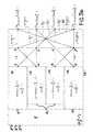
- This trelliscan be broken down into three operations referenced respectively 22, 24 and 26 (figure 4a).
- Operation 22is the initial addition operation common to all the trellises.
- This operation 24delivers the components of even index of the cosine transform in the following order: X 0 , X 8 , X 4 , X 12 , X 21 , X 10 , X 6 and X 14 .
- This trellissuccessively comprises four stages, an addition, a multiplication, an addition and a multiplication.
- the first additiondelivers eight values d o , d ,, ... d 7 according to the following relationships:
- the first four values d o , d 0 d2, d3give the components of even index X o , X 8 , X 4 and X, 2 of the cosine transform.
- the first multiplicationis defined by:
- the first multiplication applied to the components d o , d 1 , d2 and d 3is in fact the identity operation. This operation allows the second addition carried out on these components to be carried over at the same time as the second addition carried out on the four components e ,, e s , e 6 and e 7 .
- Each computation stagethus simultaneously receives all the components of a suite, which allows processing of the "pipeline" type.
- Operation 26transforms the sequence (c j ), 8 ⁇ j ⁇ 15, into components of odd index of the transform into cosine.
- This operation 26consists, in accordance with the invention, of the following four successive operations: an addition, a multiplication, an addition, a multiplication.
- the elements e irepresent the different values of cosTFD, sinTFD, TCD and TSD appearing in Figure 3b.
- the components f ;, where 8 ⁇ i ⁇ 15, delivered by the second addition stagerepresent cosTFD + TCD and sinTFD + TSD. that is to say the quantities delivered by operation 18 of FIG. 3b.
- the corresponding trellisindeed has only seven stages including three multiplication stages.
- This latticeis represented in the form of a block of three operations referenced respectively 28, 30 and 32.
- This circuitincludes in series 5 stages of calculations referenced 114, 116, 118, 120 and 122. These circuits each include 16 inputs and 16 outputs.
- the stages 114, 116 and 120are addition stages of the form a ⁇ b and the stages 118 and 122 are multiplication stages of the form ⁇ a ⁇ ⁇ b.
- the calculation performed by the stage of row k, where k is between 1 and 5,corresponds to the step of row k of the trellis shown in FIGS. 4a, 4b and 4c.
- FIGS. 7 and 8particular embodiments of an addition stage and with reference to FIGS. 9 and 10 particular embodiments of a multiplication stage.
- the circuit shown in Figure 6further includes dual memories 124, 126, 128 and 130 each arranged in series between two successive stages.
- each double memorycomprises two series of 16 memory cells. More generally, the size of each series is equal to N.
- Each series of N cells of a double memorycan receive the N values delivered by the stage which precedes it.
- the two series of the same memoryoperate in rocker.
- a seriesreceives the N values delivered by the previous stage while the other series delivers the N values stored on the next floor.
- the role of each seriesis reversed; the receiving series becomes transmitting and the transmitting series receiving.
- These double memoriesare used to synchronize the data flows between the different stages of calculations and thus allow processing of the pipeline type. In the case of sequential processing without a pipeline, these double memories can be deleted.
- each addition stagecomprises a single adder and a single subtractor
- each multiplicative stagecomprises two multipliers, an adder and a subtractor.
- the processing of the N values received by the stageis done in this case sequentially. It is then necessary to add a double memory between each calculation stage.
- a buffer memory 132can be arranged at the input of the addition stage 114.
- FIG. 7represents a first embodiment of an addition stage. It essentially comprises two input buffers 134, 136 for storing numbers a and b, an adder 138, a subtractor 140 and two output buffers 142, 144.
- the adder 138has a control input 139 which controls either the addition of the two numbers contained in the input buffers, i.e. the transmission of one of these numbers.
- the subtractor 140likewise comprises an input 141 having a similar role.
- the output buffer 142can thus receive a + b, a or b; the output buffer 144 a-b, a or -b.
- FIG. 8illustrates an alternative embodiment of the addition stage.
- the subtractor and the adderare replaced by an adder-subtractor 148 having two control inputs 147, 149 to define the number delivered to the output buffer 146 which can be equal to a, -b, a + b or a-b.
- the addition stages represented in FIGS. 7 and 8also include a sequencer and an addressing means (not shown), the latter being used to load the input buffers with numbers contained in the memory preceding this stage and for store the content of an output buffer in the following memory.
- FIG. 9represents a first embodiment of a multiplication stage. It comprises four input buffers 150, 152, 154 and 156 respectively containing the numbers ⁇ , ⁇ , a and b, two multipliers 158 and 160 for delivering the products aa and 8b, an adder-subtractor 162 having two control inputs 161 , 163 and an output buffer 164 receiving, according to the signals applied to the control inputs 161 and 163, aa, ⁇ b, ⁇ a + ⁇ b or ⁇ a- ⁇ b.
- the input buffers 154 and 156receive numbers from the memory preceding the multiplicative stage.
- the input buffers 150 and 152are loaded with numbers contained in a read-only memory 149 associated with this stage. This also includes a sequencer and an addressing means (not shown).
- the input buffers 150 and 152can receive the coefficients a and 8 respectively, but also the coefficients ⁇ and ⁇ .
- the buffer 164can receive the numbers ⁇ b, ⁇ a, 8a-ab, ⁇ a + ⁇ b. If it is not possible to orient each coefficient a and ⁇ indifferently towards the input buffers 150 and 152, two circuits must be provided like that of FIG. 9, one in which the input buffers 150 and 152 respectively receive a and ⁇ and the other in which they respectively receive ⁇ and a.
- a first alternative embodiment of the circuit of FIG. 9consists in replacing the adder-subtractor 162 by an adder and a separate subtractor. In this case, four multipliers are necessary, two being associated with the adder and two with the subtractor.
- FIG. 10A second alternative embodiment is shown in FIG. 10. This circuit is advantageous in the case where a lower processing speed is accepted.
- the elements identical to those of Figure 9have the same references.
- the input buffers 152 and 156 and the multiplier 160have been eliminated.
- a memory 166 of the accumulator type with one input and two outputsis disposed between the multiplier 158 and the adder-subtractor 162.
- the memory 166 and the adder-subtractor 162can be replaced by an adder-subtractor having an accumulator type input.
- the advantage of this embodimentis that it requires only a single multiplier, which is very advantageous from the economic point of view.
- lattices corresponding to the calculation of the cosine transform according to the inventionhave been indicated.
- the cosine processing carried out on a signaloften aims to carry out a processing of this signal in the frequency domain. This is generally followed by the inverse cosine transform of this processed signal.
- the lattice corresponding to the inverse cosine transformis very easily obtained from the lattice of the direct transform. It is enough indeed to replace the calculation operations by their transposed and to reverse the order of these operations, as indicated with reference to Figures 3a and 3b.
- FIG. 12shows the block diagram of the circuit associated with this inverse transformation.
- the calculation stagesare identical to those of the circuit of FIG. 6, but their order is reversed. Between these calculation stages, double memories 166, 168, 170 and 172 are inserted, the role of which is identical to memories 124, 126, 128 and 130 of the circuit of FIG. 7. Furthermore, memory 174 located at the input of the circuit of FIG. 12 plays a role identical to that of the memory 132 of the circuit of FIG. 6.
Landscapes
- Physics & Mathematics (AREA)
- Engineering & Computer Science (AREA)
- General Physics & Mathematics (AREA)
- Mathematical Physics (AREA)
- Mathematical Analysis (AREA)
- Mathematical Optimization (AREA)
- Computational Mathematics (AREA)
- Pure & Applied Mathematics (AREA)
- Data Mining & Analysis (AREA)
- Theoretical Computer Science (AREA)
- Discrete Mathematics (AREA)
- Algebra (AREA)
- Databases & Information Systems (AREA)
- Software Systems (AREA)
- General Engineering & Computer Science (AREA)
- Complex Calculations (AREA)
Abstract
Translated fromFrenchDescription
Translated fromFrenchLa présente invention a pour objets un circuit de calcul rapide de la transformée en cosinus d'un signal discret et un circuit de calcul rapide de la transformée en cosinus inverse d'un signal discret. Ces transformées sont utilisées notamment dans le traitement des signaux d'images numériques, et en particulier pour le codage et le décodage des images de haute résolution. L'invention concerne les transformées en cosinus discrète, directe ou inverse, dans lesquelles le signal à traiter est représenté par N points. N est de la forme 2", où n est un entier.The subject of the present invention is a circuit for rapidly calculating the cosine transform of a discrete signal and a circuit for rapidly calculating the inverse cosine transform of a discrete signal. These transforms are used in particular in the processing of digital image signals, and in particular for the coding and decoding of high resolution images. The invention relates to the discrete cosine transforms, direct or inverse, in which the signal to be processed is represented by N points. N is of the
De manière générale, la transformée en cosinus d'une suite (x;), 0 £ i 5 N-1, représentant le signal discrétisé à traiter, en une suite (Xi),0 ≦ i 5 N-1 est obtenue par une suite d'opérateurs, chaque opérateur recevant de l'opérateur précédent un ensemble de N points et délivrant à l'opérateur suivant un ensemble de N points qui s'obtiennent à partir des points reçus en entrée par des opérations mathématiques simples. Ces opérations mathématiques sont essentiellement des additions et des multiplications auxquelles peuvent s'ajouter éventuellement une permutation.In general, the cosine transform of a sequence (x; ), 0 £ i 5 N-1, representing the discretized signal to be processed, into a sequence (Xi ), 0 ≦ i 5 N-1 is obtained by a series of operators, each operator receiving from the preceding operator a set of N points and delivering to the following operator a set of N points which are obtained from the points received as input by simple mathematical operations. These mathematical operations are essentially additions and multiplications to which a permutation can possibly be added.
Dans la présente invention, le circuit de calcul de la transformée en cosinus comporte une suite d'étages, chaque étage réalisant un opérateur et faisant apparaître N nombres intermédiaires, chacun étant une combinaison linéaire d'au plus deux nombres de l'étage précédent.In the present invention, the cosine transform calculation circuit comprises a series of stages, each stage producing an operator and showing N intermediate numbers, each being a linear combination of at most two numbers of the preceding stage.
Chaque opérateur peut être représenté mathématiquement par une matrice de taille NxN. Le circuit de la transformée en cosinus est alors défini par un produit de matrices. Dans le cas où ces matrices sont orthogonales, elles sont facilement inversibles : en effet, leur inverse est égale, éventuellement à un facteur multiplicatif près, à leur transposée. Le circuit de la transformée inverse en cosinus est alors défini par le produit des matrices transposées, prises dans l'ordre inverse de celui du produit des matrices de la transformée directe.Each operator can be represented mathematically by a matrix of size Nx N. The circuit of the cosine transform is then defined by a product of matrices. In the case where these matrices are orthogonal, they are easily invertible: indeed, their inverse is equal, possibly to a multiplicative factor near, to their transpose. The circuit of the inverse cosine transform is then defined by the product of the transposed matrices, taken in the reverse order to that of the product of the matrices of the direct transform.
Dans le circuit de l'invention, les matrices de la transformée directe ne sont pas orthogonales. Cependant, le produit de chaque matrice par sa transposée est une matrice diagonale, et on constate que la transformation inverse est définie par le produit desdites matrices transposées, effectué dans l'ordre inverse du produit des matrices de la transformée directe, multiplié par un coefficient égal à 2N. Le circuit de la transformée inverse s'obtient ainsi simplement en inversant l'ordre des étages du circuit de la transformée directe, le coefficient 2N étant soit inclus dans l'un des étages multiplicatifs de la transformée directe soit obtenu au moyen d'un étage multiplicatif supplémentaire.In the circuit of the invention, the matrices of the direct transform are not orthogonal. However, the product of each matrix by its transpose is a diagonal matrix, and we note that the inverse transformation is defined by the product of said transposed matrices, carried out in the reverse order of the product of the matrices of the direct transform, multiplied by a coefficient equal to 2N. The reverse transform circuit is thus obtained simply by reversing the order of the stages of the direct transform circuit, the coefficient 2N being either included in one of the multiplicative stages of the direct transform or obtained by means of a stage additional multiplicative.
Un étage additif de la forme a±b, définit la valeur d'un point de sortie comme la somme ou la différence des valeurs de deux points d'entrée. Un étage multiplicatif de la forme α.a±β.b, associe à chaque point de sortie la somme, ou la différence, de la valeur de deux points d'entrée affectés de coefficients prédéterminés a et β. Cet étage peut être muni de moyens pour échanger les coefficients a et β de manière à produire αa±βb ou βa±αb.An additive stage of the form a ± b, defines the value of an exit point as the sum or the difference of the values of two entry points. A multiplicative stage of the form α.a ± β.b, associates with each output point the sum, or the difference, of the value of two input points assigned to predetermined coefficients a and β. This stage can be provided with means for exchanging the coefficients a and β so as to produce αa ± βb or βa ± αb.
L'opérateur d'un étage peut ne pas s'appliquer à tous les points d'entrée ; la valeur de certains points de sortie est alors simplement égale à la valeur d'un point d'entrée ou à son opposé. Un tel opérateur est dit à état transparent Le circuit 74181 de Texas Instruments est un exemple d'un additionneur-soustracteur à état transparent.The floor operator may not apply to all entry points; the value of certain exit points is then simply equal to the value of an entry point or its opposite. Such an operator is said to be in transparent state The circuit 74181 from Texas Instruments is an example of an adder-subtractor in transparent state.
Sur ler plan pratique, un étage additif comporte au moins un additionneur-soustracteur. Un étage multiplicatif est plus complexe puisqu'il requiert au moins un multiplieur avec accumalateur ou un multiplieur avec un additionneur-soustracteur. Ces circuits doivent être rapides pour traiter en temps réel des signaux d'images tels que des signaux vidéo. Ce sont des circuits onéreux.In practical terms, an additive stage includes at least one adder-subtractor. A multiplicative stage is more complex since it requires at least a multiplier with accumulator or a multiplier with an adder-subtractor. These circuits must be fast to process real-time image signals such as video signals. These are expensive circuits.
Le nombre d'additionneur-soustracteurs et de multiplieurs d'un de calcul rapide de la transformée ern cosinus est donc un critére particuliérement important dans le domaine de L'invention. Il faut par ailleurs noter que le coût d'un multiplieur est notablement plus important que le coût d'un additionneur et que la diminution du nombre d'étages multiplicatifs dans le circuit est particuliérement recherchée.The number of adder-subtractors and multipliers of a rapid computation of the ern cosine transform is therefore a particularly important criterion in the field of the invention. It should also be noted that the cost of a multiplier is significantly greater than the cost of an adder and that the reduction in the number of multiplicative stages in the circuit is particularly sought after.
On connait un procédé de calcul rapide de la transformée en cosinus par l'article "A fast compu- tational algorithm for the discrete cosine transform " de W.H. CHEN et al paru dans IEEE Transactions on Communications, vol.235, n°9, pages 1004 à 1009.We know a fast calculation process of the cosine transform by the article "A fast computational algorithm for the discrete cosine transform" by WH CHEN et al published in IEEE Transactions on Communications, vol.235, n ° 9, pages 1004 to 1009.
Dans cet article, le procédé de calcul rapide de la transformée en cosinus est défini par une matrice [AN] égale à un produit de matrices de taille NxN. Chaque matrice représente un opérateur et correspond à un étage du circuit.In this article, the rapid calculation process of the cosine transform is defined by a matrix [AN ] equal to a product of matrices of size Nx N. Each matrix represents an operator and corresponds to a stage of the circuit.
La matrice [AN] est égale à;
Les 2n-3 matrices se décomposent en n-1 matrices multiplicatives et n-2 matrices additives. Les matrices additives sont celles dans lesquelles les coefficients non nuls sont égaux à ±1. Les matrices multiplicatives comportent des termes en sinus ou en cosinus.The 2n-3 matrices break down into n-1 multiplicative matrices and n-2 additive matrices. Additive matrices are those in which the non-zero coefficients are equal to ± 1. Multiplicative matrices have sine or cosine terms.
Le circuit de transformée en cosinus décrit dans cet article comprend donc n-1 étages multiplicatifs et n-1 étages additifs, en tenant compte de l'étage correspondant à la matrice [BN ]. On ne compte pas d'étage pour matrice de permutation PN qui ne constitue pas un calcul proprement dit.The cosine transform circuit described in this article therefore comprises n-1 multiplicative stages and n-1 additive stages, taking into account the stage corresponding to the matrix [BN ]. One does not count of stage for permutation matrix PN which does not constitute a computation proper.
Le circuit connu de calcul rapide de la transformée en cosinus qui vient d'être décrit a été légèrement modifié pour un traitement pipe-line. Ces modifications consistent essentiellement à retarder d'un ou plusieurs étages le calcul effectué sur certains points de l'ensemble des N points traités et à prévoir des opérateurs à 4 entrées. Ceci permet de faire travailler en parallèle tous les étages du circuit mettant en oeuvre le procédé.The known circuit for rapidly calculating the cosine transform which has just been described has been slightly modified for pipeline processing. These modifications essentially consist in delaying by one or more stages the calculation carried out on certain points of the set of N points treated and in providing for operators with 4 inputs. This makes it possible to make all the stages of the circuit implementing the method work in parallel.
On pourra se reporter à l'article "A highspeed FDCT processor for real-time processing of NTSC color TV signal", de A. JALALI et K.R. RAO paru dans IEEE Transactions on Electromagnetic Com- patibility, vol.24, n°2, mai 1982, pages 278 à 286 pour une description plus détaillée de ce circuit.We can refer to the article "A highspeed FDCT processor for real-time processing of NTSC color TV signal", by A. JALALI and KR RAO published in IEEE Transactions on Electromagnetic Compatibility, vol.24, n ° 2, May 1982, pages 278 to 286 for a more detailed description of this circuit.
L'invention a pour objet un circuit de calcul rapide de la transformée en cosinus comportant un nombre d'étages inférieur au nombre d'étages des circuits connus. Le gain d'étages dans le circuit de l'invention porte principalement sur les étages multiplicatifs. Ceci est important du point de vue économique car, ainsi qu'on l'a souligné plus haut, le prix d'un multiplieur est particulièrement élevé.The subject of the invention is a circuit for rapidly calculating the cosine transform comprising a number of stages lower than the number of stages of known circuits. The gain of stages in the circuit of the invention relates mainly to the multiplicative stages. This is important from an economic point of view because, as pointed out above, the price of a multiplier is particularly high.
Le gain d'un étage est atteint pour Nk32, où N = 2 " et n est un entier.The gain of a stage is reached for Nk32, where N = 2 "and n is an integer.
L'invention a également pour objet un circuit de calcul rapide de la transformée en cosinus dans lequel les étages, sauf un premier étage d'addition, se composent de deux demi-étages indépendants appelés demi-étage supérieur et demi-étage inférieur, la suite des demi-étages supérieurs permettant le calcul des composantes d'indice pair de la transformée en cosinus et la suite des demi-étages inférieurs permettant le calcul des composantes d'indice impair de la transformée en cosinus.The invention also relates to a circuit for rapidly calculating the cosine transform in which the stages, except for a first addition stage, consist of two independent half-stages called upper half-stage and lower half-stage, the continuation of the upper half-stages allowing the computation of the components of even index of the transform in cosine and the continuation of the lower half-stages allowing the computation of the components of odd index of the transform in cosine.
Par demi-étages indépendants, on entend qu'un signal délivré, par exemple, par un demi-étage supérieur ne dépend que de signaux reçus de ce demi-étage supérieur.By independent half-stages, it is meant that a signal delivered, for example, by an upper half-stage depends only on signals received from this upper half-stage.
Cette structure présente l'avantage de construire un circuit de calcul rapide de la transformée en cosinus de taille N à partir d'un circuit de calcul rapide de la transformée en cosinus de taille N2, et ainsi, par récurrence, de permettre un circuit pour une taille N quelconque.This structure has the advantage of constructing a circuit for rapidly calculating the cosine transform of size N from a circuit for rapidly calculating the cosine transform of size N2, and thus, by induction, allowing a circuit for any size N.
De manière précise, l'invention a pour objet un circuit de calcul rapide de la transformée en cosinus (X,), 0≦i≦N-1, où N=2n, nk4, d'un signal discrétisé défini par une suite (x;), 0≦i≦N-1, caractérisé en ce qu'il comprend :
- -un premier étage d'addition recevant la suite (xj ), O≦j≦N-1, et délivrant une première suite (x ), O≦j≦ N2 -1 ,où x =xj+XN-1-j, et une seconde suite (yj), O≦j≦ N2 -1, où yj=xj =XN-1-j ;
- -un ensemble de demi-étages supérieurs reliés en série, le premier demi-étage supérieur recevant la première suite (x ), 0≦j≦N2 -1, et le dernier demi-étage supérieur délivrant la suite (X2q), 0≦q≦ N2 -1, des composantes d'indice pair de la transformée en cosinus, le signal délivré sur chaque sortie de chaque demi-étage étant obtenu par combinaison linéaire d'au plus deux signaux appliqués sur chacune de ses entrées, ledit ensemble de demi-étages supérieurs étant défini par récurrence sur la taille N,Iedit ensemble de demi-étages supérieurs constituant un circuit de transformée en cosinus pour N/2 points, ledit circuit comprenant en série, pour N=8, un étage d'addition, un étage de multiplication, un étage d'addition et un étage de multiplication ;
- -un ensemble de demi-étages inférieurs reliés en série, le premier demi-étage inférieur recevant la seconde suite (yj), 0≦j≦ N2 -1, et le dernier demi-étage inférieur délivrant la suite (X2q+1), 0≦q≦N2. 1, des composantes d'indice impair de la transformée en cosinus, le signal délivré sur chaque sortie de chaque demi-étage étant obtenu par combinaison linéaire d'au plus deux signaux appliqués sur chacune de ses entrées, l'ensemble de demi-étages inférieurs comprenant en série :
- a) un premier demi-étage inférieur d'addition délivrant une troisième suite (x3i ), 0≦j≦No -1, où
x =y 4j+2 + y4j+1, une quatrième suite - (xj ),
0≦j≦N4 -1, où x


pour j> -1, et une cinquième suite (x - ),
0≦j≦N8 -1 où x 2j =y4+2 -y4j+1. - b) une suite de demi-étages inférieurs d'addition ou de multiplication dèlivrant une sixième suite (α2q+1), 0≦q≦N8 -1, égale aux parties réelles des composantes d'indice impair de la transformée de Fourier d'ordre N2 de la quatrième suite, une septième suite (β2q+1 ), 0≦q≦N8 -1 égale aux parties imaginaires des composantes d'indice impair de la transformée de Fourier d'ordre N2 de la quatrième suite, une huitième suite (δ2q+1, 0≦q≦N8 -1 égale aux composantes d'indice impair de la transformée en sinus d'ordre N4 de la cinquième suite, une neuvième suite (yzq+1, 0≦q≦ -1 égale aux composantes d'indice impair de la transformée en cosinus d'ordre N4 de la troisième suite,
- c) un deuxième demi-étage inférieur d'addition pour délivrer les suites (α2q+1 + y2q+1), 0≦q≦N8-1, (α2q+1 -Y2q+1 ). 0≦q≦N8 -1, (β2q+1 -δ2q+1), 0≦q≦N8 -1, et (β2q+1 -δ2q+1), 0≦q≦
N8 1, - d) un demi-étage inférieur de multiplication délivrant la suite (X2q+1), 0≦q≦N2 -1, des composantes d'indice impair de la transformée en cosinus d'ordre N de la suite (xj), 0≦j≦N-1.
- a) un premier demi-étage inférieur d'addition délivrant une troisième suite (x3i ), 0≦j≦No -1, où


- -a first addition stage receiving the sequence (xj ), O ≦ j ≦ N-1, and delivering a first sequence (x), O ≦ j ≦ N2 -1, where x = xj + XN-1 -j , and a second sequence (yj ), O ≦ j ≦ N2 -1, where yj = xj =XN -1-j;
- -a set of upper half-stages connected in series, the first upper half-stage receiving the first sequence (x), 0 ≦ j ≦ N2 -1, and the last upper half-stage delivering the sequence (X2 q), 0 ≦ q ≦ N2 -1, components of even index of the cosine transform, the signal delivered on each output of each half-stage being obtained by linear combination of at most two signals applied to each of its inputs, said set of upper half-stages being defined by induction on the size N, said set of upper half-stages constituting a cosine transform circuit for N / 2 points, said circuit comprising in series, for N =8 , a stage of addition, a multiplication stage, an addition stage and a multiplication stage;
- -a set of lower half-stages connected in series, the first lower half-stage receiving the second sequence (yj ), 0 ≦ j ≦ N2 -1, and the last lower half-stage delivering the sequence (X2q +1 ), 0 ≦ q ≦ N2. 1, components of odd index of the cosine transform, the signal delivered on each output of each half-stage being obtained by linear combination of at most two signals applied to each of its inputs, the set of lower half-stages comprising in series:
- a) a first lower addition half-stage delivering a third sequence (x3i), 0 ≦ j ≦ No -1, where
x = y 4j + 2 + y4j + 1, a fourth sequence - (xj ),
0 ≦ j ≦ N4 -1, where x
for j> -1, and a fifth sequence (x -),
0 ≦ j ≦ N8 -1 where x 2j =y4 + 2 -y4j + 1 . - b) a sequence of lower half-stages of addition or multiplication delivering a sixth sequence (α2q + 1 ), 0 ≦ q ≦ N8 -1, equal to the real parts of the components of odd index of the Fourier transform d order N2 of the fourth sequence, a seventh sequence (β2q + 1 ), 0 ≦ q ≦ N8 -1 equal to the imaginary parts of the components of odd index of the Fourier transform of order N2 of the fourth sequence, a eighth sequence (δ2q + 1 , 0 ≦ q ≦ N8 -1 equal to the components of odd index of the sine transform of order N4 of the fifth sequence, a ninth sequence (yzq + 1 , 0 ≦ q ≦ - 1 equal to the components of odd index of the cosine transform of order N4 of the third sequence,
- c) a second lower addition half-stage for delivering the sequences (α2q + 1 + y2q + 1 ), 0 ≦ q ≦ N8-1, (α2q + 1 -Y2q + 1 ). 0 ≦ q ≦ N8 -1, (β2q + 1 -δ2q + 1 ), 0 ≦ q ≦ N8 -1, and (β2q + 1 -δ2q + 1 ), 0 ≦ q ≦
N8 1, - d) a lower multiplication half-stage delivering the sequence (X2q + 1 ), 0 ≦ q ≦ N2 -1, components of odd index of the cosine transform of order N of the sequence (xj ), 0 ≦ j ≦ N-1.
- a) a first lower addition half-stage delivering a third sequence (x3i), 0 ≦ j ≦ No -1, where
De manière préférée, les ensembles de demi-étages supérieurs et de demi-étages inférieurs comprennent un nombre identique de demi-étages d'addition.Preferably, the sets of upper half-stages and lower half-stages comprise an identical number of addition half-stages.
De manière préférée, l'ensemble de demi-étages supérieurs et l'ensemble de demi-étages inférieurs comprennent un nombre identique de demi-étages de multiplication, certains demi-étages de multiplication étant éventuellement égaux à l'opération identité.Preferably, the set of upper half-stages and the set of lower half-stages comprise an identical number of multiplication half-stages, certain multiplication half-stages possibly being equal to the identity operation.
De manière préférée, un demi-étage supérieur de rang déterminé et le demi-étage inférieur de même rang sont du même type, c'est-à-dire tous les deux des étages de multiplication.Preferably, an upper half-stage of determined rank and the lower half-stage of the same rank are of the same type, that is to say both of the multiplication stages.
De manière préférée, la suite de demi-étages inférieurs, délivrant la sixième suite égale aux parties réelles des composantes d'indice impair de la transformée de Fourier d'ordre N2 de la quatrième suite, est composée d'étages d'addition et de multiplication dont le nombre, l'ordre et le type sont ceux d'un circuit de transformée en cosinus pour une suite de N4 points, ledit circuit comprenant pour N =4, un étage d'addition et un étage de multiplication.Preferably, the series of lower half-stages, delivering the sixth series equal to the real parts of the components of odd index of the Fourier transform of order N2 of the fourth series, is composed of stages of addition and multiplication, the number, order and type of which are those of a cosine transform circuit for a sequence of N4 points, said circuit comprising for N = 4, an addition stage and a multiplication stage.
De manière préférée, chaque ensemble de demi-étages comprend n-2 demi-étages d'addition et E(n-12 ) demi-étages de multiplication, où E est la fonction partie entière, certains demi-étages de multiplication étant éventuellement égaux à l'operation identité.Preferably, each set of half-stages comprises n-2 half-stages of addition and E (n-12) half-stages of multiplication, where E is the whole part function, certain half-stages of multiplication being possibly equal to the identity operation.
L'invention a également pour objet un circuit de calcul rapide de la transformée inverse en cosinus d'un signal discret. Ce circuit. s'obtient aisément à partir du circuit de la transformée directe. On constate en effet que la suite des étages du circuit de la transformée directe, prise dans l'ordre inverse de celle de la transformée directe, constitue à un facteur multiplicatif près égal à 2N, un circuit de transformée inverse en cosinus. La démonstration de cette propriété, bien que ne présentant mathématiquement aucune difficulté, sort du cadre de cette description. Cette démonstration repose sur le fait que le produit de la matrice associée à -chaque étage de la transformée directe par sa transposée est égale à une matrice diagonale. Le coefficient multiplicatif 2N peut être intégré dans l'un des étages multiplicatifs de la transformée directe ; il peut aussi être pris en compte sous la forme d'un étage multiplicatif supplémentaire, qui peut être par exemple en position terminale.The invention also relates to a circuit for rapidly calculating the inverse cosine transform of a discrete signal. This circuit. is easily obtained from the direct transform circuit. It is in fact observed that the sequence of stages of the direct transform circuit, taken in the reverse order to that of the direct transform, constitutes, to a multiplicative factor close to 2N, a reverse transform circuit in cosine. The demonstration of this property, although presenting no mathematical difficulty, is beyond the scope of this description. This demonstration is based on the fact that the product of the matrix associated with each stage of the direct transform by its transpose is equal to a diagonal matrix. The multiplicative coefficient 2N can be integrated into one of the multiplicative stages of the direct transform; it can also be taken into account in the form of an additional multiplicative stage, which can for example be in the end position.
De par sa structure analogue à celle du circuit de la transformée directe, il apparat à l'évidence que le circuit de la transformée inverse peut être construit par récurrence pour des valeurs de N successives.By virtue of its structure analogous to that of the circuit of the direct transform, it appears evidently that the circuit of the inverse transform can be constructed by induction for successive values of N.
Les coefficients de la matrice associée à un étage de la transformée directe sont en général contenus dans une mémoire morte. Cette mémoire ne peut pas être utilisée pour l'étage correspondant de la transformée inverse, sauf si des moyens sont prévus pour modifier l'adressage de la mémoire afin d'échanger les lignes et les colonnes de la matrice des coefficients. Il peut paraître plus simple de remplacer la mémoire morte contenant la matrice de la transformée directe par une autre mémoire morte contenant la matrice transposée. Le même étage peut donc être utilisé pour la transformée directe ou pour la transformée inverse par simple changement de la mémoire morte contenant les coefficients de la matrice.The coefficients of the matrix associated with a stage of the direct transform are generally contained in a read-only memory. This memory cannot be used for the corresponding stage of the inverse transform, unless means are provided for modifying the addressing of the memory in order to exchange the rows and the columns of the matrix of the coefficients. It may seem simpler to replace the read-only memory containing the matrix of the direct transform by another read-only memory containing the transposed matrix. The same stage can therefore be used for the direct transform or for the inverse transform by simple change of the read-only memory containing the coefficients of the matrix.
De manière précise, l'invention a pour objet un circuit de calcul rapide de la transformée inverse en cosinus (x;), 0≦i≦N-1 d'un signal discrétisé défini par une suite (X;), 0≦i≦N-1, où N = 2" et n est un nombre supérieur ou égal à 4, ledit circuit étant caractérisé en ce qu'il comprend:
- -un ensemble de demi-étages supérieurs recevant la suite (Xzq), 0≦q≦ N -1 des composantes d'indice pair de la transformée en cosinus et délivrant une première suite (x j ), 0≦j≦ N2 -1,
- -un ensemble de demi-étages inférieurs recevant la suite (
X 2q+1, 0≦q≦N2 -1 des composantes d'indice impair de la transformée en cosinus et délivrant une seconde suite (x ), 0≦jN2 -1, et - -un étage final d'addition recevant la première suite (Xj) et la seconde suite (x ) et délivrant la suite (xj), 0≦j≦N-1, chaque demi-etage supérieur, chaque demi-étage inférieur et l'étage final d'addition effectuant respectivement l'opération mathématique inverse de celle effectuée par le demi-étage supérieur de même rang, compté dans l'ordre inverse, et le premier étage d'addition du circuit de calcul rapide de la transformée en cosinus directe.
- -a set of upper half-stages receiving the sequence (Xz q), 0 ≦ q ≦ N -1 of the components of even index of the cosine transform and delivering a first sequence (xj), 0 ≦ j ≦ N2 - 1,
- -a set of lower half-stages receiving the sequence (
X 2q + 1, 0 ≦ q ≦ N2 -1 of the components of odd index of the cosine transform and delivering a second sequence (x), 0 ≦ jN2 -1, and - a final addition stage receiving the first series (Xj ) and the second series (x) and delivering the series (xj ), 0 ≦ j ≦ N-1, each upper half-stage, each lower half-stage and the final addition stage respectively performing the inverse mathematical operation to that performed by the upper half-stage of the same rank, counted in reverse order, and the first addition stage of the circuit for rapidly calculating the transform into direct cosine.
De manière préférée, le circuit de calcul rapide de la transformée directe ou inverse comprend une mémoire d'au moins N cellules de mémorisation entre le premier étage d'addition et les ensembles de demi-étages supérieur et inférieur et une mémoire d'au moins + cellules de mémorisation entre chaque demi-étage.Preferably, the circuit for rapidly calculating the direct or inverse transform comprises a memory of at least N storage cells between the first addition stage and the sets of upper and lower half-stages and a memory of at least + storage cells between each half-floor.
Selon un autre mode de réalisation, le circuit de calcul rapide de la transformée directe ou inverse comprend une mémoire double comportant deux séries d'au moins N cellules de mémorisation entre le premier étage d'addition et les ensembles de demi-étages supérieur et inférieur et une mémoire double comportant deux séries d'au moins N2 cellules de mémorisation entre chaque demi-étage.According to another embodiment, the circuit for rapidly calculating the direct or inverse transform comprises a double memory comprising two series of at least N storage cells between the first addition stage and the sets of upper and lower half-stages and a double memory comprising two series of at least N2 memory cells between each half-stage.
Ces mémoires doubles permettent un traitement de type "pipe-line", l'une des séries de N/2 cellules recevant les N/2 valeurs délivrées par le demi-étage précédent et l'autre série de N/2 cellules délivrant N/2 valeurs au demi-étage suivant. Les deux séries de cellules d'une mémoire double fonctionnent en mode bascule ou ping-pong, c'est-à-dire que les N/2 valeurs délivrées par le demi-étage précédent sont dirigées alternativement vers l'une des séries et vers l'autre série.These double memories allow processing of the "pipeline" type, one of the series of N / 2 cells receiving the N / 2 values delivered by the preceding half-stage and the other series of N / 2 cells delivering N / 2 values on the next half-floor. The two series of cells of a double memory operate in toggle or ping-pong mode, that is to say that the N / 2 values delivered by the preceding half-stage are directed alternately to one of the series and to the other series.
De manière préférée, le circuit de l'invention comprend également une mémoire à N cellules de mémorisation devant le premier étage.Preferably, the circuit of the invention also includes a memory with N memory cells in front of the first stage.
Les caractéristiques et avantages de l'invention ressortiront mieux de la description qui va suivre, donnée à titre illustratif mais nullement limitatif, en référence aux dessins annexés, sur lesquels:
- -la figure 1 est un tableau illustrant, pour différentes valeurs de N, le nombre d'étages d'addition et de multiplication dans un circuit pour le calcul rapide de la transformée en cosinus selon le procédé connu de CHEN et selon le procédé de l'invention,
- -la figure 2 est un graphe rappelant la représentation conventionnelle des opérations d'addition et de multiplication par un treillis,
- -la figure 3a représente schématiquement le treillis associé au circuit de transformée en cosinus selon l'invention et illustre la construction de ce treillis par récurrence sur le nombre N de points de signal traité,
- -la figure 3b illustre la structure de la moitié inférieure du treillis de la figure précédente qui produit les composantes d'indice impair de la transformée en cosinus,
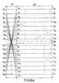
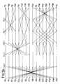
- -la figure 4a représente schématiquement un treillis associé au circuit de l'invention dans le cas n=16,
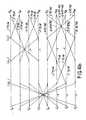
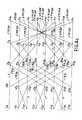
- -les figures 4b et 4c représentent respectivement des treillis produisant les composantes d'indice pair et les composantes d'indice impair de la transformée en cosinus selon le treillis de la figure 4a,
- -la figure 5a représente schématiquement un treillis associé au circuit de l'invention dans le cas N=32,
- -les figures 5b et 5c représentent respectivement des treillis produisant les composantes d'indice pair et les composantes d'indice impair de la transformée en cosinus selon le treillis de la figure 5a,
- -la figure 6 est un dessin schématique d'un mode de réalisation du circuit de l'invention,
- -la figure 7 représente un premier mode de réalisation d'un étage d'addition du circuit de la figure 6,
- -la figure 8 représente un second mode de réalisation d'un étage d'addition du circuit de la figure 6,
- -la figure 9 représente un premier mode de réalisation d'un étage de multiplication du circuit de la figure 6,
- -la figure 10 représente un second mode de réalisation d'un étage de multiplication du circuit de la figure 6,
- -la figure 11 représente un treillis associé au circuit de transformée en cosinus inverse selon l'invention dans le cas N = 16, et
- -la figure 12 est un dessin schématique d'un circuit conforme à l'invention pour le calcul rapide de la transformée inverse correspondant au treillis de la figure 10.
- FIG. 1 is a table illustrating, for different values of N, the number of stages of addition and multiplication in a circuit for the rapid calculation of the cosine transform according to the known method of CHEN and according to the method of l 'invention,
- FIG. 2 is a graph recalling the conventional representation of the operations of addition and multiplication by a trellis,
- FIG. 3a schematically represents the trellis associated with the cosine transform circuit according to the invention and illustrates the construction of this trellis by induction on the number N of signal points processed,
- FIG. 3b illustrates the structure of the lower half of the trellis of the previous figure which produces the components of odd index of the cosine transform,
- FIG. 4a schematically represents a trellis associated with the circuit of the invention in the case n = 16,
- FIGS. 4b and 4c respectively represent lattices producing the components of even index and the components of odd index of the cosine transform according to the lattice of FIG. 4a,
- FIG. 5a schematically represents a trellis associated with the circuit of the invention in the case N = 32,
- FIGS. 5b and 5c respectively represent lattices producing the components of even index and the components of odd index of the cosine transform according to the lattice of FIG. 5a,
- FIG. 6 is a schematic drawing of an embodiment of the circuit of the invention,
- FIG. 7 represents a first embodiment of an addition stage of the circuit of FIG. 6,
- FIG. 8 represents a second embodiment of an addition stage of the circuit of FIG. 6,
- FIG. 9 represents a first embodiment of a multiplication stage of the circuit of FIG. 6,
- FIG. 10 represents a second embodiment of a multiplication stage of the circuit of FIG. 6,
- FIG. 11 represents a trellis associated with the inverse cosine transform circuit according to the invention in the case N = 16, and
- FIG. 12 is a schematic drawing of a circuit according to the invention for the rapid calculation of the inverse transform corresponding to the trellis of FIG. 10.
Le tableau représenté sur la figure 1 indique, pour différentes valeurs de N, le nombre d'étages du circuit de calcul rapide de la transformée en cosinus, selon l'article de CHEN cité plus haut, et selon l'invention.The table shown in FIG. 1 indicates, for different values of N, the number of stages of the circuit for rapidly calculating the cosine transform, according to the article by CHEN cited above, and according to the invention.
Pour chacun de ces circuits, on a indiqué respectivement le nombre d'étages de multiplication notés ⊗, le nombre d'étages d'addition notés e, et le nombre d'étages total noté E.For each of these circuits, the number of multiplication stages noted ⊗, the number of addition stages noted e, and the total number of stages noted E.
On constate que pour n=2 ou n=3, les deux circuits comportent les mêmes étages. En revanche, pour n≧4 ce qui correspond aux valeurs les plus fréquemment utilisées en pratique, le circuit de l'invention comporte au moins un étage de multiplication de moins que le circuit connu décrit dans l'article de CHEN.We note that for n = 2 or n = 3, the two circuits have the same stages. On the other hand, for n ≧ 4, which corresponds to the values most frequently used in practice, the circuit of the invention comprises at least one multiplication stage less than the known circuit described in the article by CHEN.
De manière générale, le nombre d'étages de multiplication est de l'ordre de n dans le circuit de CHEN et de l'ordre de 3n/4 dans le circuit de l'invention. Le gain d'étages de multiplication est donc de l'ordre de 25%, ce qui est considérable.In general, the number of multiplication stages is of the order of n in the CHEN circuit and of the order of 3n / 4 in the circuit of the invention. The gain in multiplication stages is therefore of the order of 25%, which is considerable.
Pour le cas N = 16, 32, 64, le nombre d'étages d'addition est identique dans le circuit de CHEN et dans le circuit de l'invention. Le nombre d'étages d'addition dans le circuit de CHEN étant égal au nombre d'étages de multiplication et le nombre d'étages d'addition dans le circuit de l'invention étant égal, éventuellement à une unité près, au nombre d'étages de multiplication, il apparaît également un gain moyen de 25% d'étages d'addition dans le circuit de l'invention. Ce gain n'est effectif qu'à partir de la valeur N = 128.For the case N = 16, 32, 64, the number of addition stages is identical in the CHEN circuit and in the circuit of the invention. The number of addition stages in the CHEN circuit being equal to the number of multiplication stages and the number of addition stages in the circuit of the invention being equal, possibly to the nearest unit, to the number d 'multiplication stages, there also appears an average gain of 25% of addition stages in the circuit of the invention. This gain is only effective from the value N = 128.
On va maintenant décrire le circuit de l'invention pour plusieurs valeurs de N en utilisant la représentation conventionnelle sous forme de treillis. On va tout d'abord rappeler rapidement, en référence à la figure 2, les notations utilisées dans un treillis.We will now describe the circuit of the invention for several values of N using the conventional representation in the form of a trellis. We will first of all quickly recall, with reference to FIG. 2, the notations used in a trellis.
Le treillis de la figure 2 représente un opérateur à cinq points d'entrée et cinq points de sortie. Cet opérateur reçoit en entrée cinq valeurs a,, a2, a3, a4 et as et délivre en sortie cinq autres valeurs b,, b2, b3, b4 et bs. L'opérateur est représenté par un ensemble d'arcs reliant chacun un point d'entrée à un point de sortie. Ces arcs son affectés d'un coefficient : α, β, -1. Pour simplifier la représentation, ou convient de ne pas indiquer le coefficient lorsqu'il est égal à +1. Le coefficient associé à un arc est un coefficient multiplicatif.The trellis in Figure 2 shows an operator with five entry points and five exit points. This operator receives as input five values a ,, a2, a3 , a4 and as and outputs five other values b ,, b2 , b3 , b4 and bs . The operator is represented by a set of arcs each connecting an entry point to an exit point. These arcs are assigned a coefficient: α, β, -1. To simplify the representation, or agree not to indicate the coefficient when it is equal to +1. The coefficient associated with an arc is a multiplicative coefficient.
L'opérateur de la figure 2 réalise les opérations suivantes :


Un opérateur est dit additif si tous les coefficients associés aux arcs sont égaux à -1 ou + 1. Dans le cas contraire, l'opérateur est dit multiplicatif.An operator is said to be additive if all the coefficients associated with the arcs are equal to -1 or + 1. Otherwise, the operator is said to be multiplicative.
Pour faciliter la lecture des treillis qui vont suivre et qui illustrent le circuit de calcul rapide de la transformée en cosinus de l'invention, on va tout d'abord formaliser les opérations effectuées dans chaque treillis. Pour cela, on considère une famille (xi), 0≦i≦N-1, qui, traitée par le circuit de l'invention, est transformée en une famille (Xi), 0 ≦i≦N-1,, où les éléments Xi), sont définis de la façon suivante:
La composante Xi, où 0 ≦i ≦N-1, de la transformée en cosinus discrète d'ordre N d'une famille (Xj, O≦j≦N-1, sera notée dans la suite TCD(i, N, x).The component Xi , where 0 ≦ i ≦ N-1, of the discrete cosine transform of order N of a family (Xj , O ≦ j ≦ N-1, will be noted in the sequence TCD (i, N, x).
La formule inverse s'écrit :
Le calcul de la composante Xi de la transformée en cosinus discrète selon l'invention utilise deux expressions différentes selon la parité de i. Ces expressions sont les suivantes :


Les familles x', x2 et x3 qui apparaissent dans l'expression de la composante X2p+1 sont définies de la manière suivante :


La relation X2p =TCD(p,N 2 ,x°) montre que l'ensemble des composantes d'indice pair d'une transformée en cosinus d'une suite x de taille N est égal à l'ensemble des composantes de la transformée en cosinus d'une suite x° de taille N 2The relation X2 p = TCD (p,
En d'autres termes, pour un treillis de taille N, l'ensemble des composantes d'indice pair de la transformée s'obtient directement en appliquant le treillis de taille N/2 à la suite x°, déduite de la famille x.In other words, for a trellis of size N, the set of components of even index of the transform is obtained directly by applying the trellis of size N / 2 to the sequence x °, deduced from the family x.
De même, le calcul des composantes d'indice impair X2p+ 1 d'une suite x de N points fait appel à la transformée en cosinus d'une suite x3 de N 8 points, ainsi qu'à la transformée en sinus et à la transformée de Fourier qui sont proches, du point de vue structurel, de la transformée en cosinus.Likewise, the calculation of the components of odd index X2p + 1 of a sequence x of N points uses the cosine transform of a sequence x3 of
Il apparaît donc que le treillis de la transformée en cosinus peut être construit par récurrence sur N. On va d'abord décrire en référence aux figures 3a et 3b la structure d'un treillis de taille N correspondant à la transformée en cosinus selon l'invention mettant en oeuvre cette récurrence. On décrira ensuite des treillis correspondant aux cas particuliers N=16 et N = 32, ces treillis servant de base à la construction des treillis de tailles supérieures.It therefore appears that the lattice of the cosine transform can be built by induction on N. We will first describe with reference to Figures 3a and 3b the structure of a lattice of size N corresponding to the cosine transform according to invention using this recurrence. We will then describe lattices corresponding to the specific cases N = 16 and N = 32, these lattices serving as a basis for the construction of lattices of larger sizes.
La figure 3a représente schématiquement un treillis correspondant au calcul de la transformée en cosinus, selon l'invention, d'une suite (xi), 0 ≦i≦N-1 de taille N. Ce treillis est composé de trois opérations référencées 2, 4 et 6.FIG. 3a schematically represents a trellis corresponding to the calculation of the cosine transform, according to the invention, of a sequence (xi ), 0 ≦ i ≦ N-1 of size N. This trellis is composed of three operations referenced 2 , 4 and 6.
L'opération 2 est une addition et correspond à un étage unique. Elle transforme la suite (xj)° O≦j≦N-1 en deux suites (xO j ), O≦j≦ 2 -1, et (yj), O≦j≦N 2 -1 selon les équations :

Les opérations 4 et 6 sont parallèles, l'opération 4 produisant la suite (X2q, O≦q≦N 2 -2 des composantes d'indice pair de la transformée en cosinus à partir de la suite (x ), O≦j≦N 2 -1 et l'opération 6 produisant la suite (X2q+1), O≦q≦N 2 -1 des composantes d'indice impair de la transformée en cosinus à partir de la suite (yj, O≦j≦N 2 -1.
Les opérations 4 et 6 sont réalisées par un ensemble d'étages ayant chacun N points d'entrée et N points de sortie, chaque point de sortie de chaque étage recevant un signal obtenu par combinaison linéaire d'au plus deux signaux reçus sur des points d'entrée dudit étage.
Chaque étage se comporte comme une juxtaposition de deux demi-étages de même type, additif ou multiplicatif, ayant chacun N 2 points d'entrée et N 2 points de sortie. On appelle demi-étage supérieur la partie d'un étage associée à l'opération 4 et demi-étage inférieur la partie d'un étage associée à l'opération 6.Each stage behaves like a juxtaposition of two half-stages of the same type, additive or multiplicative, each having
L'opération 4 est réalisée par un circuit de transformée en cosinus de taille N 2 conforme à l'invention, ainsi qu'il résulte de l'expression déjà citée des composantes X2q, ou O≦q≦ N 2 -1, en fonction de la suite (x O j )O≦j≦ N-1 : X2q=TCD-(q, N 2 ,x°). Par hypothèse de récurrence, la structure de ce circuit de taille N 2 est supposée établie.
Ainsi que le montre l'expression des composantes X2q+1, où 0 ≦q≦N 2 -1, de la transformée en cosinus, l'opération 6 fait apparaître des quantités telles que la transformée en cosinus et la transformée en sinus de tailleN 4 et la transformé en cosinus et la transformée en sinus de taille , et la transformée de Fourier de tailleAs shown by the expression of the components X2q + 1 , where 0 ≦ q ≦ N 2 -1, of the cosine transform,
L'opération 6 peut ainsi être décomposée en un ensemble d'opérations plus simples. La figure 3b illustre cette décomposition. L'opération 6 comprend :
- a) -
une opération d'addition 8 recevant la suite (y j), O≦j≦N 2 -1 et délivrant trois suites (x1 ), O≦j≦N 4 -1, (x 2 j ), O≦j≦N 8 -1 et (x 3 j ), O≦j≦ N 8 -1, ces suites étant définies par les relations suivantes :


- b) -
une opération 10 recevant la suite x3 et délivrant les composantes de la transformée en cosinus d'ordre N 4 de cette suite. Compte tenu de symétries, les N/2 nombres délivrés par cette opération, égaux à TCD(2q+1, N/4, x3) pour q comprisentre 0 et N 2 -1, se ramènent à N/8 nombres différents notés (y2q+1), O≦q≦ N 8 -1, - c) -
une opération 12 recevant la suite x' et délivrant les parties réelles des composantes d'indice impair de la transformée de Fourier discrète d'ordre N/2 de cette suite. Compte tenu de symétries, les N/2 nombres délivrés par cette opération, égaux à cosTFD(2q+1,N/2,x1) pour q comprisentre 0 et N 2 -1, se ramènent à N/8 nombres différents notés (α2q+1), O≦q≦N 8 -1, - d) -
une opération 14 recevant la suite x' et délivrant les parties imaginaires des composantes d'indice impair de la transformée de Fourier discrète d'ordre N/2 de cette suite. Compte tenu de symétries, les N nombres délivrés par cette opération, égaux à sinTFD (2q+1,N/2,x1) pour q comprisentre 0 et N 2 -1, se ramènent à nombres différents notés (β2q+1), 0 ≦q≦N 8 -1, - e) -
une opération 16 recevant la suite x2 et délivrant les composantes de la transformée ensinus d'ordre N 4 de cette suite. Compte tenu de symétries, les N/2 nombres délivrés par cette opération, égaux à TSD(2q+1,N/4,x2) pour q comprisentre 0 etN 2 -1, se ramènent à N/8 nombres différents notés (δ2q+1), 0 ≦q≦N 8 -1, - f) -
une opération 18 recevant les suites impaires α, β, γ et δ, et délivrant les suites impaires λ, u, ν et p selon les équations suivantes :


- g) -
une opération 20 recevant les suites impaires λ, µ, y et p et délivrant les composantes d'indice impair de la transformée en cosinus, cette opération étant définie par les relations suivantes :


- a) -an
addition operation 8 receiving the sequence (yj), O ≦ j ≦ N 2 -1 and delivering three sequences (x1 ), O ≦ j ≦ N 4 -1, (x 2 j), O ≦ j ≦ N 8 -1 and (x 3 j), O ≦ j ≦ N 8 -1, these sequences being defined by the following relationships: - b) an
operation 10 receiving the sequence x3 and delivering the components of the cosine transform oforder N 4 of this sequence. Taking into account symmetries, the N / 2 numbers delivered by this operation, equal to TCD (2q + 1, N / 4, x3 ) for q between 0 and N 2 -1, are reduced to N / 8 different numbers noted (y2q + 1), O ≦ q ≦ N 8 -1, - c) an
operation 12 receiving the sequence x 'and delivering the real parts of the components of odd index of the discrete Fourier transform of order N / 2 of this sequence. Taking into account symmetries, the N / 2 numbers delivered by this operation, equal to cosTFD (2q + 1, N / 2, x1 ) for q between 0 and N 2 -1, are reduced to N / 8 different numbers noted (α2q + 1 ), O ≦ q ≦ N 8 -1, - d) - an
operation 14 receiving the sequence x 'and delivering the imaginary parts of the components of odd index of the discrete Fourier transform of order N / 2 of this sequence. Taking into account symmetries, the N numbers delivered by this operation, equal to sinTFD (2q + 1, N / 2, x1 ) for q between 0 and N 2 -1, are reduced to different numbers noted (β2q + 1) , 0 ≦ q ≦ N 8 -1, - e) -an
operation 16 receiving the sequence x2 and delivering the components of the transform into sine oforder N 4 of this sequence. Taking into account symmetries, the N / 2 numbers delivered by this operation, equal to TSD (2q + 1, N / 4, x2 ) for q between 0 andN 2 -1, are reduced to N / 8 different numbers noted ( δ2q + 1), 0 ≦ q ≦ N 8 -1 , - f) - an
operation 18 receiving the odd sequences α, β, γ and δ, and delivering the odd sequences λ, u, ν and p according to the following equations:
- g) an
operation 20 receiving the odd sequences λ, µ, y and p and delivering the components of odd index of the cosine transform, this operation being defined by the following relationships:
Les symétries qui permettent de réduire à N/8 le nombre des points de sortie des opérations 10, 12, 14 et 16 résultent directement des expressions TCD, TSD, cosTFD et sinTFD.The symmetries which make it possible to reduce to N / 8 the number of exit points of
Par exemple, TCD(2q + 1 + N/2,N/4,x3) s'écrit Par exemple, TCD(2q+1+N/2,N/4,x3) s'écrit
De manière générale, on a ainsi les relations suivantes pour 0 ≦q≦N 8 -1 :


II est intéressant de remarquer que les suites impaires λ et µ représentent les parties réelles des composantes d'indice impair de la transformée de Fourier d'une suite xs définie par : x 5 j = y2j si O≦j≦N 4 -1 et x5 j = -yN.2j-1 si N/4 ≦j≦N 2 -1. Ces composantes sont cosTFD(2q + 1,N,x5), pour q compris entre 0 et N 2 -1.It is interesting to note that the odd sequences λ and µ represent the real parts of the components of odd index of the Fourier transform of a sequence xs defined by: x 5 j = y2j if O ≦ j ≦ N 4 -1 and x5 j = -yN.2j-1 if N / 4 ≦ j ≦ N 2 -1 . These components are cosTFD (2q + 1, N, x5 ), for q between 0 and N 2 -1.
De même, les suites impaires v et p représentent les parties imaginaires des composantes d'indice impair de la transformée de Fourier de la suite xs et sont notées, sinTFD(2q+1,N,x5) pour q compris entre 0 et -1.Likewise, the odd sequences v and p represent the imaginary parts of the components of odd index of the Fourier transform of the sequence xs and are noted, sinTFD (2q + 1, N, x5 ) for q between 0 and -1.
Les opérations 12 et 14 peuvent ainsi être construites par récurrence sur N. Par ailleurs, l'opération 16 est structurellement identique à l'opération 10 et peut également se construire par récurrence.The
Enfin, on peut vérifier que les opérations 12, 14, 16 comportent un nombre d'étages inférieur ou égal au nombre d'étages de l'opération 10 et que pour chacune des opérations ces étages sont du même type (additif ou multiplicatif).Finally, it can be verified that
La récurrence peut donc être bâtie sur le nombre d'étages nécessaires pour réaliser l'opération 10. Cette opération qui calcule les composantes impaires de la transformée en cosinus de taille N/4 est réalisée par une suite d'étages égale aux étages de calcul de la transformée en cosinus complète privée de l'étage d'addition initial. Comme l'opération 8 est une addition, on peut dire que les opérations 8 et 10 nécessitent un ensemble d'étages identique à l'ensemble des étages d'un circuit de la transformée en cosinus de taille N/4.The recurrence can therefore be built on the number of stages necessary to carry out
Ainsi, ayant un ensemble d'étages formant un circuit de transformée en cosinus de taille N/4 - (correspondant aux opérations 8 et 10), il suffit d'ajouter deux étages d'addition et un étage de multiplication (correspondant respectivement aux opérations 2, 18 et 20) pour obtenir un circuit de calcul de la transformée en cosinus de taille N.Thus, having a set of stages forming a cosine transform circuit of size N / 4 - (corresponding to
Les figures 3a et 3b illustrent le graphe de la transformée directe en cosinus. Le graphe de la transformée inverse s'en déduit aisément. Il suffit de reprendre les opérations dans l'ordre inverse, en remplaçant ces opérations par les opérations transposées, celles-ci étant définies comme étant les opérations dont les matrices associées sont les transposées des matrices associées aux opérations de la transformée directe.Figures 3a and 3b illustrate the graph of the direct cosine transform. The inverse transform graph is easily deduced from this. It suffices to repeat the operations in the reverse order, by replacing these operations with the transposed operations, these being defined as being the operations whose associated matrices are the transposed matrices associated with the operations of the direct transform.
On va maintenant décrire successivement un treillis correspondant au cas N=16 et un treillis correspondant au cas N = 32.We will now describe successively a trellis corresponding to the case N = 16 and a trellis corresponding to the case N = 32.
Les figures 4a, 4b et 4c représentent un treillis de la transformée en cosinus pour le cas N=16. Ce treillis peut être décomposé en trois opérations référencées respectivement 22, 24 et 26 (figure 4a). L'opération 22 est l'opération d'addition initiale commune à tous les treillis. Cette étape consiste à transformer la suite (Xj), 0 ≦j≦15, en une suite (cj), O≦j≦15, cj =xj+x15-j, c8+J = +xj-x15-j, où O≦j≦7.FIGS. 4a, 4b and 4c represent a lattice of the cosine transform for the case N = 16. This trellis can be broken down into three operations referenced respectively 22, 24 and 26 (figure 4a).
L'opération 24 appliquée à la suite (Cj), 0 ≦j≦7 est représentée sur la figure 4b par le treillis de la transformée en cosinus de taille N=8, selon l'invention. Cette opération 24 délivre les composantes d'indice pair de la transformée en cosinus dans l'ordre suivant : X0, X8, X4, X12, X21, X10, X6 et X14.
Ce treillis comporte successivement quatre étapes, une addition, une multiplication, une addition et une multiplication. La première addition délivre huit valeurs do, d,, ...d7 selon les relations suivantes :

Les quatre premières valeurs do, d0 d2, d3 donnent les composantes d'indice pair Xo, X8, X4 et X,2 de la transformée en cosinus.The first four values do , d0 d2, d3 give the components of even index Xo , X8 , X4 and X,2 of the cosine transform.
La première multiplication est définie par :


Notons que la première multiplication appliquée aux composantes do, d1, d2 et d3 est en fait l'opération d'identité. Cette opération permet de reporter la deuxième addition effectuée sur ces composantes en même temps que la deuxième addition effectuée sur les quatre composantes e,, es, e6 et e7. Chaque étage de calcul reçoit ainsi simultanément toutes les composantes d'une suite, ce qui permet un traitement de type "pipe-line".Note that the first multiplication applied to the components do , d1 , d2 and d3 is in fact the identity operation. This operation allows the second addition carried out on these components to be carried over at the same time as the second addition carried out on the four components e ,, es , e6 and e7 . Each computation stage thus simultaneously receives all the components of a suite, which allows processing of the "pipeline" type.
La deuxième addition est définie par :


L'opération 26 transforme la suite (cj), 8≦j≦15, en composantes d'indice impair de la transformée en cosinus. Cette opération 26 est constituée, conformément à l'invention, des quatre opérations successives suivantes : une addition, une multiplication, une addition, une multiplication.Operation 26 transforms the sequence (cj ), 8 ≦ j ≦ 15, into components of odd index of the transform into cosine. This operation 26 consists, in accordance with the invention, of the following four successive operations: an addition, a multiplication, an addition, a multiplication.
Le treillis détaillé correspondant à cette opération 26 est représenté sur la figure 4c.The detailed trellis corresponding to this operation 26 is shown in FIG. 4c.
Ces opérations sont définies par les équations suivantes :
- - première addition (tableau I),
- -première multiplication (tableau II),
- -deuxième addition (tableau III),
- -deuxième multiplication (tableau IV),
- - first addition (Table I),
- -first multiplication (table II),
- -second addition (Table III),
- -second multiplication (Table IV),
Dans ce treillis, les éléments ei, où 8≦i≦15, représentent les différentes valeurs de cosTFD, sinTFD, TCD et TSD apparaissant dans la figure 3b. Les composantes f;, où 8≦i≦15, délivrées par le second étage d'addition représentent cosTFD + TCD et sinTFD + TSD. c'est-à-dire les quantités délivrées par l'opération 18 de la figure 3b.In this lattice, the elements ei , where 8 ≦ i ≦ 15, represent the different values of cosTFD, sinTFD, TCD and TSD appearing in Figure 3b. The components f ;, where 8 ≦ i ≦ 15, delivered by the second addition stage represent cosTFD + TCD and sinTFD + TSD. that is to say the quantities delivered by
Le treillis selon l'invention représenté sur les figures 4a, 4b et 4c apporte un gain d'un étage de multiplication par rapport au treillis selon l'art antérieur. Un gain identique est obtenu dans le cas N=32. Le treillis correspondant comporte en effet seulement sept étages dont trois étages de multiplication.The trellis according to the invention shown in Figures 4a, 4b and 4c provides a gain of a multiplication stage compared to the trellis according to the prior art. An identical gain is obtained in the case N = 32. The corresponding trellis indeed has only seven stages including three multiplication stages.
On a représenté sur la figure 5a le treillis correspondant au procédé de calcul rapide de la transformée en cosinus selon l'invention dans le cas N = 32. Ce treillis est représenté sous la forme d'un bloc de trois opérations référencées respectivement 28, 30 et 32. L'opération 28 est l'addition initiale commune à tous les treillis, elle transforme la suite (x;), O≦i≦31, en une suite (ai),O≦i≦31, définie par aj=xj+x31-j et a16+j = xj-x31-j, pour O≦j≦15.FIG. 5a shows the lattice corresponding to the method for rapidly calculating the cosine transform according to the invention in the case N = 32. This lattice is represented in the form of a block of three operations referenced respectively 28, 30 and 32.
L'opération 30 représente le treillis suivant l'invention pour N = 16. Il transforme les 16 premières composantes ao, a,, ..., a,s en composantes d'indice pair de la transformée en cosinus de la suite (x; ), 0≦i≦31, dans l'ordre suivant : Xo, X16, X8, X24, X4, X20, X12, X28, X30, X6, X18, X10, X22, X14, X26 et X2.Operation 30 represents the trellis according to the invention for N = 16. It transforms the first 16 components ao, a ,, ..., a, s into components of even index of the cosine transform of the sequence (x ;), 0 ≦ i ≦ 31, in the following order: Xo , X16 , X8 , X24 , X4 , X20 , X12 , X28 , X30 , X6 , X18 , X10 , X22 , X14 , X26 and X2 .
L'opération 30 est représentée par le treillis de la figure 5b. Elle est fonctionnellement identique au treillis représenté sur les figures 4a, 4b et 4c et correspondant à N=16. Il en diffère légèrement dans sa réalisation par l'adjonction entre les deux premières étapes additives d'une étape multiplicative égale à l'opération identité. Cette étape supplémentaire permet de synchroniser les additions et les multiplications réalisées par les opérations 30 et 32, ce qui rend possible un traitement de type "pipe-line".Operation 30 is represented by the trellis of Figure 5b. It is functionally identical to the trellis shown in FIGS. 4a, 4b and 4c and corresponding to N = 16. It differs slightly in its realization by the addition between the first two additive steps of a multiplicative step equal to the identity operation. This additional step makes it possible to synchronize the additions and multiplications carried out by
On va maintenant décrire, en référence à la figure 5c, le treillis correspondant à l'opération 32.We will now describe, with reference to FIG. 5c, the trellis corresponding to
Celle-ci transforme les 16 dernières composantes a16, a17, ..., a31 en composantes d'indice impair de la transformée en cosinus de la suite (x;), O≦i≦31. Elle est constituée d'une suite d'étapes comprenant successivement une première addition, une deuxième addition, une première multiplication, une deuxième multiplication, une troisième addition et une troisième multiplication. Ces opérations sont définies par les relations suivantes :
- -première addition (tableau V),
- -deuxième addition (tableau VI),
- -première multiplication (tableau VII),
- -deuxième multiplication (tableau VIII),
- -troisième addition (tableau IX),
- -troisième multiplication (tableau X).
- -first addition (table V),
- -second addition (Table VI),
- -first multiplication (table VII),
- -second multiplication (table VIII),
- -third addition (Table IX),
- -third multiplication (table X).
Les calculs correspondant aux treillis représentés sur les figures 3a à 5c sont réalisés par des circuits comportant en série des étages d'addition et des étages de multiplication. A titre d'exemple, on va décrire le schéma de principe d'un circuit correspondant à N=16. Ce circuit est représenté sur la figure 6.The calculations corresponding to the trellis shown in FIGS. 3a to 5c are carried out by circuits comprising in series addition stages and multiplication stages. As an example, we will describe the block diagram of a circuit corresponding to N = 16. This circuit is shown in Figure 6.
Ce circuit comprend en série 5 étages de calculs référencés 114, 116, 118, 120 et 122. Ces circuits comprennent chacun 16 entrées et 16 sorties. Les étages 114, 116 et 120 sont des étages d'addition de la forme a±b et les étages 118 et 122 sont des étages de multiplication de la forme αa±βb. Le calcul effectué par l'étage de rang k, où k est compris entre 1 et 5, correspond à l'étape de rang k du treillis représenté sur les figures 4a, 4b et 4c.This circuit includes in
On décrira en référence aux figures 7 et 8 des modes de réalisation particulier d'un étage d'addition et en référence aux figures 9 et 10 des modes de réalisation particuliers d'un étage de multiplication.There will be described with reference to FIGS. 7 and 8 particular embodiments of an addition stage and with reference to FIGS. 9 and 10 particular embodiments of a multiplication stage.
Le circuit représenté sur la figure 6 comprend en outre des mémoires doubles 124, 126, 128 et 130 disposées chacune en série entre deux étages successifs. Dans le cas représenté sur la figure, chaque mémoire double comporte deux séries de 16 cellules de mémorisation. Plus généralement, la taille de chaque série est égale à N. Chaque série de N cellules d'une mémoire double peut recevoir les N valeurs délivrées par l'étage qui la précède.The circuit shown in Figure 6 further includes
Les deux séries d'une même mémoire fonctionnent en bascule. A un instant donné, une série reçoit les N valeurs délivrées par l'étage précédent alors que l'autre série délivre les N valeurs mémorisées à l'étage suivant. A l'instant suivant, le rôle de chaque série est inversé ; la série réceptrice devient émettrice et la série émettrice, réceptrice.The two series of the same memory operate in rocker. At a given instant, a series receives the N values delivered by the previous stage while the other series delivers the N values stored on the next floor. At the next instant, the role of each series is reversed; the receiving series becomes transmitting and the transmitting series receiving.
Ces mémoires doubles sont utilisées pour synchroniser les flux de données entre les différents étages de calculs et permettre ainsi un traitement de type pipe-line. Dans le cas d'un traitement séquentiel sans pipe-line, ces mémoires doubles peuvent être supprimées.These double memories are used to synchronize the data flows between the different stages of calculations and thus allow processing of the pipeline type. In the case of sequential processing without a pipeline, these double memories can be deleted.
En général, chaque étage d'addition comporte un seul additionneur et un seul soustracteur, et de même, chaque étage multiplicatif comporte deux multiplieurs, un additionneur et un soustracteur. Le traitement des N valeurs reçues par l'étage se fait dans ce cas de manière séquentielle. Il est alors nécessaire d'adjoindre entre chaque étage de calcul une mémoire double. De plus, une mémoire tampon 132 peut être disposée en entrée de l'étage d'addition 114.In general, each addition stage comprises a single adder and a single subtractor, and likewise, each multiplicative stage comprises two multipliers, an adder and a subtractor. The processing of the N values received by the stage is done in this case sequentially. It is then necessary to add a double memory between each calculation stage. In addition, a
On va maintenant décrire des modes de réalisation d'un étage d'addition et d'un étage de multiplication en référence aux figures 7 à 10.We will now describe embodiments of an addition stage and a multiplication stage with reference to FIGS. 7 to 10.
La figure 7 représente un premier mode de réalisation d'un étage d'addition. Il comprend essentiellement deux tampons d'entrée 134, 136 pour mémoriser des nombres a et b, un additionneur 138, un soustracteur 140 et deux tampons de sortie 142, 144. L'additionneur 138 comporte une entrée de commande 139 qui commande soit l'addition des deux nombres contenus dans les tampons d'entrée, soit la transmission de l'un de ces nombres. Le soustracteur 140 comprend de même une entrée 141 ayant un rôle semblable. Le tampon de sortie 142 peut ainsi recevoir a+b, a ou b ; le tampon de sortie 144 a-b, a ou -b.FIG. 7 represents a first embodiment of an addition stage. It essentially comprises two
La figure 8 illustre une variante de réalisation de l'étage d'addition. Le soustracteur et l'additionneur sont remplacés par un additionneur-soustracteur 148 ayant deux entrées de commande 147, 149 pour définir le nombre délivré au tampon de sortie 146 qui peut être égal à a, -b, a+b ou a-b.FIG. 8 illustrates an alternative embodiment of the addition stage. The subtractor and the adder are replaced by an adder-
Les étages d'addition représentés sur les figures 7 et 8 comprennent également un séquenceur et un moyen d'adressage (non représentés), ce dernier étant utilisé pour charger les tampons d'entrée avec des nombres contenus dans la mémoire précédant cet étage et pour stocker dans la mémoire suivante le contenu d'un tampon de sortie.The addition stages represented in FIGS. 7 and 8 also include a sequencer and an addressing means (not shown), the latter being used to load the input buffers with numbers contained in the memory preceding this stage and for store the content of an output buffer in the following memory.
La figure 9 représente un premier mode de réalisation d'un étage de multiplication. Il comprend quatre tampons d'entrée 150, 152, 154 et 156 contenant respectivement les nombres α, β, a et b, deux multiplieurs 158 et 160 pour délivrer les produits aa et 8b, un additionneur-soustracteur 162 ayant deux entrées de commande 161, 163 et un tampon de sortie 164 recevant, selon les signaux appliqués sur les entrées de commande 161 et 163, aa, βb, αa+βb ou αa-βb.FIG. 9 represents a first embodiment of a multiplication stage. It comprises four
Les tampons d'entrée 154 et 156 reçoivent des nombres de la mémoire précédant l'étage multiplicatif. Les tampons d'entrée 150 et 152 sont chargés avec des nombres contenus dans une mémoire morte 149 associée à cet étage. Celui-ci comprend également un séquenceur et un moyen d'adressage (non représentés).The input buffers 154 and 156 receive numbers from the memory preceding the multiplicative stage. The input buffers 150 and 152 are loaded with numbers contained in a read-
Les tampons d'entrée 150 et 152 peuvent recevoir respectivement les coefficients a et 8, mais aussi les coefficients β et α. Dans ce cas, le tampon 164 peut recevoir les nombres αb, βa, 8a-ab, βa+αb. S'il n'est pas possible d'orienter chaque coefficient a et β indifféremment vers les tampons d'entrée 150 et 152, il faut prévoir deux circuits comme celui de la figure 9, l'un dans lequel les tampons d'entrée 150 et 152 reçoivent respectivement a et β et l'autre dans lequel ils reçoivent respectivement β et a.The input buffers 150 and 152 can receive the coefficients a and 8 respectively, but also the coefficients β and α. In this case, the
Une première variante de réalisation du circuit de la figure 9 consiste à remplacer l'additionneur-soustracteur 162 par un additionneur et un soustracteur distinct. Dans ce cas, quatre multiplieurs sont nécessaires, deux étant associés à l'additionneur et deux au soustracteur.A first alternative embodiment of the circuit of FIG. 9 consists in replacing the adder-
Une seconde variante de réalisation est représentée sur la figure 10. Ce circuit est intéressant dans le cas où une vitesse de traitement moins importante est acceptée. Dans cette figure, les éléments identiques à ceux de la figure 9 portent les mêmes références. Dans cet étage, on a supprimé les tampons d'entrée 152 et 156, et le multiplieur 160. Une mémoire 166 de type accumulateur à une entrée et deux sorties, est disposée entre le multiplieur 158 et l'additionneur-soustracteur 162. La mémoire 166 et l'additionneur-soustracteur 162 peuvent être remplacés par un additionneur-soustracteur ayant une entrée de type accumulateur. L'avantage de ce mode de réalisation est de ne nécessiter qu'un seul multiplieur, ce qui est très avantageux du point de vue économique.A second alternative embodiment is shown in FIG. 10. This circuit is advantageous in the case where a lower processing speed is accepted. In this figure, the elements identical to those of Figure 9 have the same references. In this stage, the input buffers 152 and 156 and the
On a indiqué en référence aux figures 3a à 5c des treillis correspondant au calcul de la transformée en cosinus selon l'invention. Le traitement en cosinus effectué sur un signal a souvent pour but de réaliser un traitement de ce signal dans le domaine fréquentiel. Celui-ci est généralement suivi de la transformée en cosinus inverse de ce signal traité. Le treillis correspondant à la transformée inverse en cosinus s'obtient très facilement à partir du treillis de la transformée directe. Il suffit en effet de remplacer les opérations de calcul par leurs transposées et de renverser l'ordre de ces opérations, comme on l'a indiqué en référence aux figures 3a et 3b.Referring to FIGS. 3a to 5c, lattices corresponding to the calculation of the cosine transform according to the invention have been indicated. The cosine processing carried out on a signal often aims to carry out a processing of this signal in the frequency domain. This is generally followed by the inverse cosine transform of this processed signal. The lattice corresponding to the inverse cosine transform is very easily obtained from the lattice of the direct transform. It is enough indeed to replace the calculation operations by their transposed and to reverse the order of these operations, as indicated with reference to Figures 3a and 3b.
On trouvera à titre d'exemple sur la figure 11 le treillis correspondant à la transformée inverse en cosinus pour le cas N=16. Ce treillis correspond exactement au treillis de la figure 4a lu de droite à gauche avec les mêmes coefficients.One will find by way of example in figure 11 the lattice corresponding to the inverse transform in cosine for the case N =16 . This trellis exactly corresponds to the trellis of Figure 4a read from right to left with the same coefficients.
On a représenté sur la figure 12 le schéma de principe du circuit associé à cette transformation inverse. Les étages de calcul sont identiques à ceux du circuit de la figure 6, mais leur ordre est inversé. Entre ces étages de calcul sont insérées des mémoires doubles 166, 168, 170 et 172 dont le rôle est identique aux mémoires 124, 126, 128 et 130 du circuit de la figure 7. Par ailleurs, la mémoire 174 située en entrée du circuit de la figure 12 joue un rôle identique à celui de la mémoire 132 du circuit de la figure 6.


Claims (13)
Translated fromFrenchApplications Claiming Priority (2)
| Application Number | Priority Date | Filing Date | Title |
|---|---|---|---|
| FR8507717AFR2582424B1 (en) | 1985-05-22 | 1985-05-22 | CIRCUIT OF FAST CALCULATION OF THE TRANSFORMED IN COSINUS, DIRECT OR REVERSE, OF A DISCRETE SIGNAL |
| FR8507717 | 1985-05-22 |
Publications (2)
| Publication Number | Publication Date |
|---|---|
| EP0204603A1true EP0204603A1 (en) | 1986-12-10 |
| EP0204603B1 EP0204603B1 (en) | 1993-01-07 |
Family
ID=9319482
Family Applications (1)
| Application Number | Title | Priority Date | Filing Date |
|---|---|---|---|
| EP86401069AExpired - LifetimeEP0204603B1 (en) | 1985-05-22 | 1986-05-21 | Fast calculating of the direct or reverse cosine transform of a discrete signal |
Country Status (7)
| Country | Link |
|---|---|
| US (1) | US4841464A (en) |
| EP (1) | EP0204603B1 (en) |
| JP (1) | JP2710928B2 (en) |
| CA (1) | CA1252212A (en) |
| DE (1) | DE3687430T2 (en) |
| ES (1) | ES8900240A1 (en) |
| FR (1) | FR2582424B1 (en) |
Cited By (1)
| Publication number | Priority date | Publication date | Assignee | Title |
|---|---|---|---|---|
| EP0286183A1 (en)* | 1987-04-10 | 1988-10-12 | Koninklijke Philips Electronics N.V. | Television transmission system using transform coding |
Families Citing this family (26)
| Publication number | Priority date | Publication date | Assignee | Title |
|---|---|---|---|---|
| US5054103A (en)* | 1987-09-24 | 1991-10-01 | Matsushita Electric Works, Ltd. | Picture encoding system |
| EP0366435B1 (en)* | 1988-10-27 | 1998-12-23 | Matsushita Electric Industrial Co., Ltd. | Orthogonal and inverse orthogonal transform apparatus |
| US5163103A (en)* | 1988-12-27 | 1992-11-10 | Kabushiki Kaisha Toshiba | Discrete cosine transforming apparatus |
| US5029122A (en)* | 1988-12-27 | 1991-07-02 | Kabushiki Kaisha Toshiba | Discrete cosine transforming apparatus |
| IT1235263B (en)* | 1989-06-02 | 1992-06-26 | Sgs Thomson Microelectronics | METHOD AND DEVICE FOR THE ARITHMETIC CALCULATION OF TWO-DIMENSIONAL PROCESSES. |
| US5053985A (en)* | 1989-10-19 | 1991-10-01 | Zoran Corporation | Recycling dct/idct integrated circuit apparatus using a single multiplier/accumulator and a single random access memory |
| US5875266A (en)* | 1990-07-31 | 1999-02-23 | Fujitsu Limited | Image data processing a method and apparatus |
| DE69131808T2 (en) | 1990-07-31 | 2000-03-16 | Fujitsu Ltd. | Process and device for image data processing |
| US5343501A (en)* | 1991-02-19 | 1994-08-30 | Matsushita Electric Industrial Co., Ltd. | Orthogonal transform apparatus for video signal processing |
| US5257213A (en)* | 1991-02-20 | 1993-10-26 | Samsung Electronics Co., Ltd. | Method and circuit for two-dimensional discrete cosine transform |
| US5818742A (en)* | 1991-06-24 | 1998-10-06 | Atmel Corporation | Apparatus to transform time to frequency and frequency to time of data signals |
| EP0557204A3 (en)* | 1992-02-21 | 1995-10-18 | Sony Corp | Discrete cosine transform apparatus and inverse discrete cosine transform apparatus |
| US5224062A (en)* | 1992-03-17 | 1993-06-29 | Sun Microsystems, Inc. | Method and apparatus for fast implementation of inverse discrete cosine transform in a digital image processing system using optimized lookup tables |
| JP3323950B2 (en)* | 1992-03-17 | 2002-09-09 | サン・マイクロシステムズ・インコーポレーテッド | Method of performing IDCT in a digital image processing system and IDCT processor therefor |
| KR940004467A (en)* | 1992-08-26 | 1994-03-15 | 오오가 노리오 | Discrete cosine inverters and their inverses |
| US5654910A (en)* | 1992-08-26 | 1997-08-05 | Sony Corporation | Processing method and apparatus for performing 4 ×4 discrete cosine transformation or inverse discrete cosing transformation |
| JPH06103301A (en)* | 1992-09-17 | 1994-04-15 | Sony Corp | (8x8) discrete cosine transforming circuit and (8x8) discrete cosine inverse transforming circuit |
| US5523847A (en)* | 1992-10-09 | 1996-06-04 | International Business Machines Corporation | Digital image processor for color image compression |
| JP2725544B2 (en)* | 1992-11-12 | 1998-03-11 | 日本電気株式会社 | DCT and inverse DCT operation device and operation method thereof |
| JPH06149862A (en)* | 1992-11-13 | 1994-05-31 | Sony Corp | Matrix data multiplying method and device |
| US5345408A (en)* | 1993-04-19 | 1994-09-06 | Gi Corporation | Inverse discrete cosine transform processor |
| JPH06334986A (en)* | 1993-05-19 | 1994-12-02 | Sony Corp | Weighted cosine transform method |
| KR100836050B1 (en)* | 2001-05-23 | 2008-06-09 | 엘지전자 주식회사 | High speed Fourier transform arithmetic unit |
| AU2001273587A1 (en)* | 2001-06-15 | 2002-01-14 | Kim Jongil | Fast efficient computation of the discrete cosine transform (dct) of digital video data |
| US7883604B2 (en)* | 2005-12-15 | 2011-02-08 | Kimberly-Clark Worldwide, Inc. | Creping process and products made therefrom |
| US9824066B2 (en)* | 2011-01-10 | 2017-11-21 | Qualcomm Incorporated | 32-point transform for media data coding |
Citations (1)
| Publication number | Priority date | Publication date | Assignee | Title |
|---|---|---|---|---|
| US4385363A (en) | 1978-12-15 | 1983-05-24 | Compression Labs, Inc. | Discrete cosine transformer |
Family Cites Families (3)
| Publication number | Priority date | Publication date | Assignee | Title |
|---|---|---|---|---|
| US4449194A (en)* | 1981-09-25 | 1984-05-15 | Motorola Inc. | Multiple point, discrete cosine processor |
| FR2561011B1 (en)* | 1984-03-09 | 1986-09-12 | Cit Alcatel | PROCESSOR FOR CALCULATING A DISCRETE INVERSE COSINUS TRANSFORM |
| FR2561010B1 (en)* | 1984-03-09 | 1986-09-12 | Cit Alcatel | PROCESSOR FOR CALCULATING A DISCRETE COSINUS TRANSFORM |
- 1985
- 1985-05-22FRFR8507717Apatent/FR2582424B1/ennot_activeExpired
- 1986
- 1986-05-20USUS06/865,108patent/US4841464A/ennot_activeExpired - Lifetime
- 1986-05-21JPJP61117147Apatent/JP2710928B2/ennot_activeExpired - Fee Related
- 1986-05-21CACA000509653Apatent/CA1252212A/ennot_activeExpired
- 1986-05-21DEDE8686401069Tpatent/DE3687430T2/ennot_activeExpired - Fee Related
- 1986-05-21EPEP86401069Apatent/EP0204603B1/ennot_activeExpired - Lifetime
- 1986-05-22ESES555225Apatent/ES8900240A1/ennot_activeExpired
Patent Citations (1)
| Publication number | Priority date | Publication date | Assignee | Title |
|---|---|---|---|---|
| US4385363A (en) | 1978-12-15 | 1983-05-24 | Compression Labs, Inc. | Discrete cosine transformer |
Non-Patent Citations (2)
| Title |
|---|
| DE A. JALALI; K.R. RAO: "A high- speed FDCT processor for real-time processing of NTSC color TV signal", IEEE TRANSACTIONS ON ELECTROMAGNETIC COMPATIBILITY, vol. 24, no. 2, May 1982 (1982-05-01), pages 278 - 286 |
| IEEE TRANSACTIONS ON ELECTROMAGNETIC COMPATIBILITY, vol. EMC-24, no. 2, mai 1982, pages 278-286, IEEE, New York, US; A. JALALI et al.: "A high-speed FDCT processor for real-time processing of NTSC color TV signal"* |
Cited By (1)
| Publication number | Priority date | Publication date | Assignee | Title |
|---|---|---|---|---|
| EP0286183A1 (en)* | 1987-04-10 | 1988-10-12 | Koninklijke Philips Electronics N.V. | Television transmission system using transform coding |
Also Published As
| Publication number | Publication date |
|---|---|
| DE3687430T2 (en) | 1993-06-03 |
| ES8900240A1 (en) | 1989-05-01 |
| CA1252212A (en) | 1989-04-04 |
| JP2710928B2 (en) | 1998-02-10 |
| DE3687430D1 (en) | 1993-02-18 |
| FR2582424B1 (en) | 1989-06-30 |
| ES555225A0 (en) | 1989-05-01 |
| JPS61272870A (en) | 1986-12-03 |
| US4841464A (en) | 1989-06-20 |
| FR2582424A1 (en) | 1986-11-28 |
| EP0204603B1 (en) | 1993-01-07 |
Similar Documents
| Publication | Publication Date | Title |
|---|---|---|
| EP0204603B1 (en) | Fast calculating of the direct or reverse cosine transform of a discrete signal | |
| EP0248729A1 (en) | Monodimensional cosine transform calculators and image coding and decoding devices using such calculators | |
| EP0147326B1 (en) | Digital filter with variable phase and bandpass | |
| EP0206847B1 (en) | Cosine transform calculating devices, picture coding and decoding device comprising such calculating devices | |
| EP0046708A2 (en) | Digital distributed-arithmetic processing circuit using multiplexers at the input of a memory | |
| EP3809287B1 (en) | Method for simplifying a filter and associated devices | |
| EP0309037A1 (en) | Serial pipeline multiplier | |
| EP0942530B1 (en) | Programmable processor circuit comprising a reconfigurable memory for the embodiment of a digital filter | |
| FR2471094A1 (en) | INTERPOLATOR CIRCUIT INCREASING THE RATE OF WORDS OF A DIGITAL SIGNAL OF THE TYPE USED IN TELEPHONE DIGITAL SWITCHING SYSTEMS AND LINE JETOR WITH SUCH CIRCUIT | |
| EP3809288B1 (en) | Method for filtering with zero latency and associated devices | |
| FR2638303A1 (en) | IMPROVED INTERPOLATIVE FILTER | |
| EP3809286B1 (en) | Method for filtering with reduced latency and associated devices | |
| EP0154341A1 (en) | Discrete cosine transform processor | |
| EP0014151A1 (en) | Method of treating successive signal samples and digital filter for carrying out the method | |
| EP0262032B1 (en) | Binary adder having a fixed operand, and a parallel/serial multiplier comprising such an adder | |
| EP0259231A1 (en) | Device for the determination of the digital transform of a signal | |
| EP0350121A1 (en) | Integrated circuit and picture-processing device | |
| FR2568036A1 (en) | CALCULATION CIRCUIT | |
| EP0338899B1 (en) | Method for coding and decoding blocks of data and apparatus for carrying out said coding and decoding method | |
| EP0237382B1 (en) | Digital sampled signal cosine transforming device | |
| EP0924626A1 (en) | Pipelined fast Fourier processor | |
| EP0175623A1 (en) | Device for the real-time processing of a digital signal by convolution | |
| WO1995004963A1 (en) | Device for electronically calculating a fourier transform and method of minimizing the size of internal data paths within such a device | |
| FR2761550A1 (en) | DIGITAL FILTER FOR FRACTIONAL DELAYS | |
| WO1999030251A1 (en) | Method for computing fast fourier transform and inverse fast fourier transform |
Legal Events
| Date | Code | Title | Description |
|---|---|---|---|
| PUAI | Public reference made under article 153(3) epc to a published international application that has entered the european phase | Free format text:ORIGINAL CODE: 0009012 | |
| AK | Designated contracting states | Kind code of ref document:A1 Designated state(s):BE DE GB IT NL SE | |
| 17P | Request for examination filed | Effective date:19870509 | |
| 17Q | First examination report despatched | Effective date:19900126 | |
| GRAA | (expected) grant | Free format text:ORIGINAL CODE: 0009210 | |
| AK | Designated contracting states | Kind code of ref document:B1 Designated state(s):BE DE GB IT NL SE | |
| RAP2 | Party data changed (patent owner data changed or rights of a patent transferred) | Owner name:FRANCE TELECOM | |
| REF | Corresponds to: | Ref document number:3687430 Country of ref document:DE Date of ref document:19930218 | |
| ITF | It: translation for a ep patent filed | ||
| GBT | Gb: translation of ep patent filed (gb section 77(6)(a)/1977) | Effective date:19930318 | |
| ITTA | It: last paid annual fee | ||
| PLBE | No opposition filed within time limit | Free format text:ORIGINAL CODE: 0009261 | |
| STAA | Information on the status of an ep patent application or granted ep patent | Free format text:STATUS: NO OPPOSITION FILED WITHIN TIME LIMIT | |
| 26N | No opposition filed | ||
| EAL | Se: european patent in force in sweden | Ref document number:86401069.9 | |
| REG | Reference to a national code | Ref country code:GB Ref legal event code:IF02 | |
| PGFP | Annual fee paid to national office [announced via postgrant information from national office to epo] | Ref country code:DE Payment date:20040423 Year of fee payment:19 | |
| PGFP | Annual fee paid to national office [announced via postgrant information from national office to epo] | Ref country code:SE Payment date:20040426 Year of fee payment:19 | |
| PGFP | Annual fee paid to national office [announced via postgrant information from national office to epo] | Ref country code:NL Payment date:20040427 Year of fee payment:19 | |
| PGFP | Annual fee paid to national office [announced via postgrant information from national office to epo] | Ref country code:GB Payment date:20040428 Year of fee payment:19 | |
| PGFP | Annual fee paid to national office [announced via postgrant information from national office to epo] | Ref country code:BE Payment date:20040503 Year of fee payment:19 | |
| PG25 | Lapsed in a contracting state [announced via postgrant information from national office to epo] | Ref country code:IT Free format text:LAPSE BECAUSE OF NON-PAYMENT OF DUE FEES;WARNING: LAPSES OF ITALIAN PATENTS WITH EFFECTIVE DATE BEFORE 2007 MAY HAVE OCCURRED AT ANY TIME BEFORE 2007. THE CORRECT EFFECTIVE DATE MAY BE DIFFERENT FROM THE ONE RECORDED. Effective date:20050521 Ref country code:GB Free format text:LAPSE BECAUSE OF NON-PAYMENT OF DUE FEES Effective date:20050521 | |
| PG25 | Lapsed in a contracting state [announced via postgrant information from national office to epo] | Ref country code:SE Free format text:LAPSE BECAUSE OF NON-PAYMENT OF DUE FEES Effective date:20050522 | |
| PG25 | Lapsed in a contracting state [announced via postgrant information from national office to epo] | Ref country code:BE Free format text:LAPSE BECAUSE OF NON-PAYMENT OF DUE FEES Effective date:20050531 | |
| BERE | Be: lapsed | Owner name:*CASSIMATIS ERIC Effective date:20050531 Owner name:*GUICHARD JACQUES Effective date:20050531 | |
| PG25 | Lapsed in a contracting state [announced via postgrant information from national office to epo] | Ref country code:NL Free format text:LAPSE BECAUSE OF NON-PAYMENT OF DUE FEES Effective date:20051201 Ref country code:DE Free format text:LAPSE BECAUSE OF NON-PAYMENT OF DUE FEES Effective date:20051201 | |
| EUG | Se: european patent has lapsed | ||
| GBPC | Gb: european patent ceased through non-payment of renewal fee | Effective date:20050521 | |
| NLV4 | Nl: lapsed or anulled due to non-payment of the annual fee | Effective date:20051201 | |
| BERE | Be: lapsed | Owner name:*CASSIMATIS ERIC Effective date:20050531 Owner name:*GUICHARD JACQUES Effective date:20050531 |