EP0202460B1 - Display systems for vehicle - Google Patents
Display systems for vehicleDownload PDFInfo
- Publication number
- EP0202460B1 EP0202460B1EP86105024AEP86105024AEP0202460B1EP 0202460 B1EP0202460 B1EP 0202460B1EP 86105024 AEP86105024 AEP 86105024AEP 86105024 AEP86105024 AEP 86105024AEP 0202460 B1EP0202460 B1EP 0202460B1
- Authority
- EP
- European Patent Office
- Prior art keywords
- display
- projective
- display device
- front glass
- image
- Prior art date
- Legal status (The legal status is an assumption and is not a legal conclusion. Google has not performed a legal analysis and makes no representation as to the accuracy of the status listed.)
- Expired - Lifetime
Links
Images


Classifications
- G—PHYSICS
- G02—OPTICS
- G02B—OPTICAL ELEMENTS, SYSTEMS OR APPARATUS
- G02B27/00—Optical systems or apparatus not provided for by any of the groups G02B1/00 - G02B26/00, G02B30/00
- G02B27/01—Head-up displays
- B—PERFORMING OPERATIONS; TRANSPORTING
- B60—VEHICLES IN GENERAL
- B60K—ARRANGEMENT OR MOUNTING OF PROPULSION UNITS OR OF TRANSMISSIONS IN VEHICLES; ARRANGEMENT OR MOUNTING OF PLURAL DIVERSE PRIME-MOVERS IN VEHICLES; AUXILIARY DRIVES FOR VEHICLES; INSTRUMENTATION OR DASHBOARDS FOR VEHICLES; ARRANGEMENTS IN CONNECTION WITH COOLING, AIR INTAKE, GAS EXHAUST OR FUEL SUPPLY OF PROPULSION UNITS IN VEHICLES
- B60K35/00—Instruments specially adapted for vehicles; Arrangement of instruments in or on vehicles
- B60K35/20—Output arrangements, i.e. from vehicle to user, associated with vehicle functions or specially adapted therefor
- B60K35/21—Output arrangements, i.e. from vehicle to user, associated with vehicle functions or specially adapted therefor using visual output, e.g. blinking lights or matrix displays
- B60K35/22—Display screens
- G—PHYSICS
- G02—OPTICS
- G02B—OPTICAL ELEMENTS, SYSTEMS OR APPARATUS
- G02B27/00—Optical systems or apparatus not provided for by any of the groups G02B1/00 - G02B26/00, G02B30/00
- G02B27/01—Head-up displays
- G02B27/0101—Head-up displays characterised by optical features
- B—PERFORMING OPERATIONS; TRANSPORTING
- B60—VEHICLES IN GENERAL
- B60K—ARRANGEMENT OR MOUNTING OF PROPULSION UNITS OR OF TRANSMISSIONS IN VEHICLES; ARRANGEMENT OR MOUNTING OF PLURAL DIVERSE PRIME-MOVERS IN VEHICLES; AUXILIARY DRIVES FOR VEHICLES; INSTRUMENTATION OR DASHBOARDS FOR VEHICLES; ARRANGEMENTS IN CONNECTION WITH COOLING, AIR INTAKE, GAS EXHAUST OR FUEL SUPPLY OF PROPULSION UNITS IN VEHICLES
- B60K2360/00—Indexing scheme associated with groups B60K35/00 or B60K37/00 relating to details of instruments or dashboards
- B60K2360/20—Optical features of instruments
- B60K2360/33—Illumination features
- B60K2360/334—Projection means
- G—PHYSICS
- G02—OPTICS
- G02B—OPTICAL ELEMENTS, SYSTEMS OR APPARATUS
- G02B27/00—Optical systems or apparatus not provided for by any of the groups G02B1/00 - G02B26/00, G02B30/00
- G02B27/01—Head-up displays
- G02B27/0101—Head-up displays characterised by optical features
- G02B2027/0118—Head-up displays characterised by optical features comprising devices for improving the contrast of the display / brillance control visibility
- G—PHYSICS
- G02—OPTICS
- G02B—OPTICAL ELEMENTS, SYSTEMS OR APPARATUS
- G02B27/00—Optical systems or apparatus not provided for by any of the groups G02B1/00 - G02B26/00, G02B30/00
- G02B27/01—Head-up displays
- G02B27/0149—Head-up displays characterised by mechanical features
- G02B2027/0154—Head-up displays characterised by mechanical features with movable elements
- G02B2027/0156—Head-up displays characterised by mechanical features with movable elements with optionally usable elements
- G—PHYSICS
- G02—OPTICS
- G02B—OPTICAL ELEMENTS, SYSTEMS OR APPARATUS
- G02B27/00—Optical systems or apparatus not provided for by any of the groups G02B1/00 - G02B26/00, G02B30/00
- G02B27/01—Head-up displays
- G02B27/0149—Head-up displays characterised by mechanical features
- G02B2027/0165—Head-up displays characterised by mechanical features associated with a head-down display
- G—PHYSICS
- G02—OPTICS
- G02B—OPTICAL ELEMENTS, SYSTEMS OR APPARATUS
- G02B27/00—Optical systems or apparatus not provided for by any of the groups G02B1/00 - G02B26/00, G02B30/00
- G02B27/01—Head-up displays
- G02B27/0179—Display position adjusting means not related to the information to be displayed
- G02B2027/0187—Display position adjusting means not related to the information to be displayed slaved to motion of at least a part of the body of the user, e.g. head, eye
Definitions
- the present inventionrelates to a vehicular display system mounted on a vehicle such as an automobile and more particularly to a vehicular display system for displaying data concerning a vehicle such as vehicle speed, engine revolutions, time and various warnings.
- a projective display unit(not shown) comprising a lens, a display device disposed within the focus of the lens and a case which houses those components therein, is mounted inside an instrument panel 1 b located in front of a steering wheel 1a of a vehicle 1, and on a dash board 1c located in front of the instrument panel 1b is disposed a half mirror at a predetermined angle relative to the above lens, the half mirror 2 having predetermined transmissivity and reflectivity.
- a display image which represents a data concerning the vehicle such as, for example, vehicle speed displayed on the above display deviceis projected on the half mirror 2 through an opening 1d formed in the dash board 1c, whereby a virtual image 3 is formed at a predetermined distance ahead of the half mirror 2.
- the driver on the driver's seatsees the virtual image 3 in an overlapped state with the external sight and thus can obtain data required for driving without taking his eyes off the external sight, thereby permitting a safe driving of the vehicle.
- the vehicle drivingis performed by drivers of various constitutions or having various habits, so the line of vision for the outside greatly differs depending on drivers during vehicular driving.
- the half mirror 2by making pivotable a mounting base end of the half mirror 2 onto the dash board 1c, the half mirror 2 can be adjusted to a suitable position, that is, the position of the virtual image 3 can be moved up and down for alignment with the line of vision of the driver.
- the movable range of the virtual image 3is restricted by the size of the half mirror 2, so where it is to cover all drivers, it becomes necessary to use the half mirror 2 having a correspondingly larger area.
- the half mirror 2is made very large, the greater part of the driver's front sight will be covered with the same mirror, thus resulting in that the driver sees the front through the half mirror 2.
- the half mirror 2is a see- through mirror, it is apparent that this mirror will be a hindrance to the driver's front sight. Besides, it exerts a bad influence upon the design of the instrument panel 1b and obstructs wiping of a front glass 1e behind the panel. Additionally, there is a serious problem also from the aspect of safety because an upper edge of the half mirror 2 faces the driver's side.
- DE-A-1 623 738there is described a display apparatus for a vehicle according to the features of the first part of claim 1, comprising an optical system for projecting a display image from a display device on a front glass of said vehicle.
- an optical system for projecting a display image from a display device on a front glass of said vehiclecomprising an optical system for projecting a display image from a display device on a front glass of said vehicle.
- the present inventionhas been accomplished in order to solve the above-mentioned problems.
- the vehicular display systemprovided for attaining the above object includes a projective display means mounted on a vehicle, the projective display means having a display device for displaying various data and functioning to project a display image of the display device onto a vehicular front glass and form a virtual image of the display image in front of the front glass; and also includes a position adjusting means for adjusting the position of the virtual image formed in front of the front glass by shifting a projective optical axis of the display image extending from the projective display means to the front glass.
- the display imageis projected on the front glass, it is not necessary to provide any special member on this side of the front glass, that is, the driver's front sight is not obstructed, and thus the display system is superior in safety, appearance and design. Further, since the position of the display image projected on the front glass can be adjusted, it is possible to form a virtual image of the display image in the most suitable position aligned with the line of vision of the driver according to the constitution and posture of each driver.
- a vehicular display system embodying the present inventionin which a later-described projective display unit 20 is mounted inside an instrument panel 10b which is located in front of a steering wheel 10a of a vehicle 10.
- the projective display unit 20projects a display image onto an inner surface of a front glass 10e located above a dash board 10c, through an opening 10d of the dash board and images the display image in front of the front glass 10e, as a virtual image 12.
- the projective display unit 20comprises a housing 201, a convex lens 202 as an optical system disposed in an opening at one end of the housing 201, and a display device 203 disposed at the bottom of the housing 201.
- the display device 203is constituted by a light transmission type liquid crystal display device comprising a liquid crystal display (LCD) cell 203a disposed inside a focus F of the convex lens 202, namely, in a position closer to the convex lens 202 than the focus F and a light source 203b, the light source 203b being a lamp which emits light to the LCD cell 203a from a rear face of the cell.
- LCDliquid crystal display
- the LCD cell 203awhich is driven by a display driver (not shown), forms a display image which represents data concerning the vehicle, e.g. vehicle speed.
- the display imageis a negative or positive image which selectively permits or does not permit the light applied to the rear face of the LCD cell 203a from the light source 203b to pass therethrough.
- the light which has passed through the LCD cell 203a in the form of the display imageis projected onto the front glass 10e through the convex lens 202, whereby a virtual image 12 of the display image is formed in front of the front glass 10e.
- An outerwall ofthe housing 201 of the projective display unit 20is provided with a rotating shaft 204 for supporting the projective display unit 20 rotatably in a space 10f which is formed inside the instrument panel 10b.
- a gear 207meshing with a gear 206 which is fixed to a rotational shaft of an electric motor 205, the motor 205 being also disposed in the space 10f.
- the rotating shaft 204, motor 205 and gears 206, 207constitute a rotation support mechanism for the projective display unit 20, which support mechanism permits the projective display unit 20 to rotate along with the rotating shaft 204 when the motor 205 is rotated forward or reverse selectively by operation of an adjusting knob mounted, for example, on the instrument panel 10b and serving as an operating means.
- the drivercan see the virtual image 12 of the display image projected on the front glass 10e, in an overlapped condition with the external sight.
- the motor 205is rotated forward or reverse by operation of the above adjusting knob to rotate the projective display unit 20 along with the rotating shaft 204 as shown in Fig. 5.
- a projective optical axis of the display image onto the front glass 10e from the projective display unit 20is changed, whereby the direction of reflected light from the front glass 10e is changed as indicated by arrows a, b and c, thus permitting the virtual image 12 to be formed in a desired position aligned with the line of vision of the driver.
- a housing 201 of the projective display unit 20is formed generally in L shape from a transparent synthetic resin material such as acrylic resin or polycarbonate resin.
- a display device 203comprising an LCD cell 203a, a light source 203b and a light source case 203c which houses the light source 203b therein and which reflects and condenses light emitted from the light source.
- a reflecting mirror 208is fixed to a central bent portion of the housing 201, and a convex lens 202 is mounted in an opening portion of the housing 201.
- a display element 209formed by a coating of fluorescent paint for example.
- a display image of the display device 203is reflected by the reflecting mirror 208 and projected onto the front glass 10e through the convex lens 202.
- Part of the light emitted from the light source 203bis incident on the housing 201 from the base end face of the housing and reaches an end face of the opening portion while being conducted through the interior of the housing, thereby illuminating the fluorescent coating as the display element 209 from the rear face thereof, whereby the frame shape of the opening end face of the housing 201 is projected on the front glass 10e and a display frame image 209a is formed around the virtual image 12 of the display image.
- the display frame image 209aalso shifts on the front glass 10e. Therefore, even if there is no display on the display device 203, the driver can know the position in which the virtual image 12 of the display image is to be formed, upon his seeing of the display frame image 209a.
- the convex lens 202has a long focal distance, and even when the display device 203 must be disposed away from the convex lens 202, the overall length of the projective display unit 20 is short, thus permitting a construction of a compact shape.
- the light from the light source 203bis conducted to the rear face of the display element 209, but when the surroundings are light, the display frame image 209a can be formed by the reflection of ambient light made by the fluorescent coating of the display element 209.
- light from a light source provided separately from the light source 203bmay be conducted to the rear face of the display element 209.
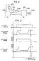
- An electric current consumed during operation of the motoris detected by a detecting resistor R, while an overcurrent in a limit position and a dash current at the time of start-up of the motor are discriminated from each other by means of a limit position detecting circuit 205b which is constituted by a comparator.
- a motor controller 205dcontrols the motor driver 205a in accordance with the result of the discrimination and the state of an operating switch 205c which functions to set the rotation of the motor 205 forwardly and reversely.
- the range of rotation of the projective display unit 20 and that of the reflecting mirror 21are each restricted by a stopper (not shown) so as not to exceed a predetermined range. Therefore, if the switch 205c is so operated as to rotate the projective display unit 20 or the reflecting mirror 21 in excess of the predetermined range as shown in Fig. 9 (I), the motor 205 becomes overloaded in the limit position and such an overcurrent as indicated by b in Fig. 9 (II) flows in the detecting resistor R.
- a voltage developed across the resistor R by the said overcurrentis detected by the limit position detecting circuit 205b, which in turn provides a signal to the motor controller 205d, whereupon the motor controller 205d outputs, for a predetermined time period, a driving voltage of a polarity opposite to that of the driving voltage so far provided, to rotate the motor 205 in the reverse direction.
- a dash current ["a" in Fig. 9 (II)] at the time of start-up in the reverse rotation of the motor 205is much smaller than that indicated by "a" in Fig. 9 (IV) which is detected when the motor 205 is stopped immediately in the limit position, and it is obviously of a magnitude different from that of the overcurrent in the limit position.
- the limit position detecting circuit 205bis prevented from being operated erroneously by the dash current.
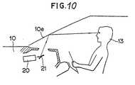
- Fig. 10illustrates a modification of the display system shown in Fig. 3 with the projective display unit 20 being rotatable.
- a distortion of image caused by the curvature of the front glass 10eis corrected by a fixed reflecting mirror 21 which is disposed in proximity to the projective display unit 20.
- Figs. 11 to 13illustrate other preferred examples of projective display units 20 in which a display device 203 is constituted by a transmission type liquid crystal display device.
- a diffusion plate 203dis disposed in a position between a light source 203b and an LCD cell 203a, sufficiently spaced from a focus F of an objective lens 202 and outside the focus F.
- the light from the light source 203bis diffused and uniformly distributed by the diffusion plate 203d and in this state it is incident on the LCD cell 203a, so that there is obtained a display image of a small luminance difference, and a spot reflection on the diffusion plate 203d is not projected in an enlarged state through the objective lens 202, thus affording an image free from glare and capable of being seen clearly.
- a diffusion plate 208a formed from a light transmissible materialis sticked to the reflection surface of the reflecting mirror 208.
- the light from the light source 203bis partially reflected irregularly by the surface of the diffusion plate 208a, while the remaining portion of the light which has passed through the diffusion plate 208a is wholly reflected by a reflecting mirror surface formed at the rear face of the diffusion plate 208a and then reflected irregularly when passing through the diffusion plate 208a again. Consequently, the effect of diffusion is improved remarkably as compared with the case where the diffusion plate alone is used.
- the whole of the light incident on the diffusion plate 208a from the light source 203bis reflected irregularly and applied to the LCD cell 203a, there is obtained a sufficiently light display image without loss of the light.
- an LCD cell 203a of a display device 203is composed of a display cell 203a-1, a negative-positive change-over cell 203a-2 and a polarizing plate 203a-3, and it is connected to a display driver 32 which receives a signal indicative of a vehicle speed from a vehicle speed sensor 30.
- the display device 203further includes a light source 203b which is composed of a high luminance light source 203b-1, a low luminance light source 203b-2 and a light source case 203b-3 which houses those light sources therein.
- the high and low luminance light sources 203b-1 and 203b-2are separated from each other by means of a half mirror 203b-4 within the light source case 203b-3 so that the light from the high luminance light source 203b-1 which has been reflected by the half mirror 203b-4 and the light from the low luminance light source 203b-2 which has passed through the half mirror 203b-4 are applied selectively to the rear face of the LCD cell 203a.
- a negative-positive change-over switch 34is provided between the negative-positive change-over cell 203a-2 and the display driver 32, while a light source change-over switch 36 is provided between the high luminance light source 203b-1 and the low luminance light source 203b-2.
- These two change-over switches 34 and 36are changed over from one to the other interlockedly with a lighting switch 38 for lamps such as clearance lamps which are turned ON during the night.
- a transparent heat reflecting filter 203b-5for preventing the influence of heat upon the LCD cell 203a.
- the lighting switch 38is OFF as shown in Fig. 14 and the change-over switches 34 and 36 interlocked therewith are in such states as shown in the figure.
- the display driver 32forms a display image Q on the display cell 203a-1 of the LCD cell 203a in accordance with a signal provided from the vehicle speed sensor 30.
- the polarizing direction of the polarizing plate 203a-1is selected so that the virtual image 12 of the display image Q in front of the front glass 10e becomes such a negative display as shown in Fig. 15.
- the high luminance light source 203b-1is turned ON.
- the light from the high luminance light source 203b-1is reflected and condensed by the inner surface of the light source case 203b-3 and is incident on the half mirror 203b-4 which is mounted inclinedly at 45°.
- the half mirror 203b-4reflects the incident light onto the rear face of the LCD cell 203a.
- the light thus incident on the LCD cell 203apasses through the LCD cell 203a in the form of a display image of the display cell 203a-1 and is projected on the front glass 10e through the convex lens 202, whereby a virtual image 12 of such a negative display as shown in Fig. 15 is formed in front of the front glass 10e.
- the lighting switch 34is turned ON as shown in Fig. 16, and when the change-over switches 34 and 36 assume the state shown interlockedly therewith, the low luminance light source 203b-2 is turned ON and a virtual image 12 of such a positive display as shown in Fig. 17 is formed in front of the front glass 10e by the action of the negative-positive change-over cell 203a-2.
- a half mirror 40is mounted at a predetermined angle between a convex lens 202 and a display device 203, and a shutter 42 is disposed rotatably between the half mirror 40 and the display device 203.
- This signalis converted to a digital signal by means of an analog-digital (A-D) converter 46, which digital signal is fed to a control circuit 48 which is constituted by a microcomputer (CPU).
- A-Danalog-digital
- a temperature detecting element 50is mounted near an LCD cell 203a of the display device 203 and an output signal from the temperature detecting element 50 is also fed to the control circuit 48 through an A-D converter 52.
- the control circuit 48provides control signals to a blower drive controller 56 which controls a blower driver 54 and also to a shutter drive controller 60 which controls a shutter driver 58.
- the shutter driver 58drives the shutter 42 which is normally closed, in an opening direction.
- the blower driver 54drives a blower 62 disposed near a light source 203b.
- the convex lens 202, half mirror 40, shutter 42 and display device 203are housed in a housing 201, the housing 201 having a ventilating hole 201a provided near the light source 203b of the display device 203.
- Numeral 32denotes a display driver for driving the LCD cell 203a of the display device 203 to form a display image and
- numeral 64denotes a light source driver for turning ON the light source 203b.
- the control circuit 48makes a discrimination on the signal provided from the light detecting element 44 and detects whether an external light of a level above a predetermined level has been incident or not. When an incidence of such an external light is detected by the control circuit 48, this control circuit provides a signal to the shutter drive controller 60.
- the shutter drive controller 60causes the shutter driver 58 to close the shutter 42 which is open, so that the sunlight is shielded by the shutter 42, whereby the LCD cell 203a is prevented from being damaged under the irradiation heat of the sunlight.
- a radiant heat from the light source 203bis detected by the temperature detecting element 50, which in turn provides a signal to the control circuit 48 through the A-D converter 52.
- the control circuit 48provides a signal to the blower drive controller 56, which in turn causes the blower driver 54 to operate the blower 62 in accordance with the signal from the control circuit 48.
- the blower driver 54Upon operation of the blower 62, the surroundings of the light source 203b are ventilated to prevent the rise in temperature of the surface of the LCD cell 203a.
Landscapes
- Physics & Mathematics (AREA)
- Engineering & Computer Science (AREA)
- General Physics & Mathematics (AREA)
- Optics & Photonics (AREA)
- Chemical & Material Sciences (AREA)
- Combustion & Propulsion (AREA)
- Transportation (AREA)
- Mechanical Engineering (AREA)
- Instrument Panels (AREA)
Description
- The present invention relates to a vehicular display system mounted on a vehicle such as an automobile and more particularly to a vehicular display system for displaying data concerning a vehicle such as vehicle speed, engine revolutions, time and various warnings.
- As a display system of this type there has heretofore been known such a display system as disclosed in Japanese Utility Model Laid-Open Publication No. 48576/75, which is shown in Fig. 1. In this known display system, a projective display unit (not shown) comprising a lens, a display device disposed within the focus of the lens and a case which houses those components therein, is mounted inside an
instrument panel 1 b located in front of asteering wheel 1a of avehicle 1, and on adash board 1c located in front of theinstrument panel 1b is disposed a half mirror at a predetermined angle relative to the above lens, thehalf mirror 2 having predetermined transmissivity and reflectivity. A display image which represents a data concerning the vehicle such as, for example, vehicle speed displayed on the above display device is projected on thehalf mirror 2 through an opening 1d formed in thedash board 1c, whereby avirtual image 3 is formed at a predetermined distance ahead of thehalf mirror 2. - Consequently, the driver on the driver's seat sees the
virtual image 3 in an overlapped state with the external sight and thus can obtain data required for driving without taking his eyes off the external sight, thereby permitting a safe driving of the vehicle. - By the way, the vehicle driving is performed by drivers of various constitutions or having various habits, so the line of vision for the outside greatly differs depending on drivers during vehicular driving. In this case, by making pivotable a mounting base end of the
half mirror 2 onto thedash board 1c, thehalf mirror 2 can be adjusted to a suitable position, that is, the position of thevirtual image 3 can be moved up and down for alignment with the line of vision of the driver. - However, the movable range of the
virtual image 3 is restricted by the size of thehalf mirror 2, so where it is to cover all drivers, it becomes necessary to use thehalf mirror 2 having a correspondingly larger area. - But, if the
half mirror 2 is made very large, the greater part of the driver's front sight will be covered with the same mirror, thus resulting in that the driver sees the front through thehalf mirror 2. Although thehalf mirror 2 is a see- through mirror, it is apparent that this mirror will be a hindrance to the driver's front sight. Besides, it exerts a bad influence upon the design of theinstrument panel 1b and obstructs wiping of afront glass 1e behind the panel. Additionally, there is a serious problem also from the aspect of safety because an upper edge of thehalf mirror 2 faces the driver's side. - In DE-A-1 623 738 there is described a display apparatus for a vehicle according to the features of the first part of
claim 1, comprising an optical system for projecting a display image from a display device on a front glass of said vehicle. However, there are no means provided for indicating the position of the display image projected from the display device on the front glass. - The present invention has been accomplished in order to solve the above-mentioned problems.
- Accordingly, it is the object of the present invention to provide a vehicular display system capable of freely changing the position of display within the driver's front sight.
- The vehicular display system provided for attaining the above object includes a projective display means mounted on a vehicle, the projective display means having a display device for displaying various data and functioning to project a display image of the display device onto a vehicular front glass and form a virtual image of the display image in front of the front glass; and also includes a position adjusting means for adjusting the position of the virtual image formed in front of the front glass by shifting a projective optical axis of the display image extending from the projective display means to the front glass.
- In the above vehicular display system of the present invention, since the display image is projected on the front glass, it is not necessary to provide any special member on this side of the front glass, that is, the driver's front sight is not obstructed, and thus the display system is superior in safety, appearance and design. Further, since the position of the display image projected on the front glass can be adjusted, it is possible to form a virtual image of the display image in the most suitable position aligned with the line of vision of the driver according to the constitution and posture of each driver.
- Fig. 1 is a perspective view showing an example of a conventional vehicular display system;
- Fig. 2 is a perspective view of a vehicular display system according to an embodiment of the present invention;
- Fig. 3 is a sectional view showing details of the display system of Fig. 2;
- Fig. 4 is a sectional view showing details of a projective display unit in Fig. 3;
- Fig. 5 is an explanatory view of the operation of the display system shown in Fig. 3;
- Figs. 6 and 7 are a sectional side view and a partially broken-away perspective view, respectively, showing a modified example of a projective display unit used in the display system of the invention;
- Fig. 8 illustrates a control circuit for a motor which drives the projective display unit in Fig. 3;
- Fig. 9 is a time chart for explaining the operation of the circuit shown in Fig. 8;
- Fig. 10 is a partially sectional view showing a modification of the display system of Fig. 3;
- Figs. 11 to 13 schematically illustrate further examples of projective display units used in the display system of the invention;
- Figs. 14 to 17 illustrate an example of a display device in the projective display unit used in the display system of the invention; and
- Fig. 18 illustrates a still further example of a projective display unit used in the display system of the invention.
- The present invention will be described in detail hereinunder with reference to the accompanying drawings.
- Referring to Figs. 2 to 4, there is illustrated a vehicular display system embodying the present invention, in which a later-described
projective display unit 20 is mounted inside aninstrument panel 10b which is located in front of asteering wheel 10a of avehicle 10. Theprojective display unit 20 projects a display image onto an inner surface of afront glass 10e located above adash board 10c, through an opening 10d of the dash board and images the display image in front of thefront glass 10e, as avirtual image 12. - The
projective display unit 20 comprises ahousing 201, aconvex lens 202 as an optical system disposed in an opening at one end of thehousing 201, and adisplay device 203 disposed at the bottom of thehousing 201. As shown in Fig. 4, thedisplay device 203 is constituted by a light transmission type liquid crystal display device comprising a liquid crystal display (LCD)cell 203a disposed inside a focus F of theconvex lens 202, namely, in a position closer to theconvex lens 202 than the focus F and alight source 203b, thelight source 203b being a lamp which emits light to theLCD cell 203a from a rear face of the cell. - The
LCD cell 203a, which is driven by a display driver (not shown), forms a display image which represents data concerning the vehicle, e.g. vehicle speed. The display image is a negative or positive image which selectively permits or does not permit the light applied to the rear face of theLCD cell 203a from thelight source 203b to pass therethrough. The light which has passed through theLCD cell 203a in the form of the display image is projected onto thefront glass 10e through theconvex lens 202, whereby avirtual image 12 of the display image is formed in front of thefront glass 10e. - An outerwall ofthe
housing 201 of theprojective display unit 20 is provided with a rotatingshaft 204 for supporting theprojective display unit 20 rotatably in aspace 10f which is formed inside theinstrument panel 10b. Mounted on the rotatingshaft 204 is agear 207 meshing with agear 206 which is fixed to a rotational shaft of anelectric motor 205, themotor 205 being also disposed in thespace 10f. The rotatingshaft 204,motor 205 andgears projective display unit 20, which support mechanism permits theprojective display unit 20 to rotate along with the rotatingshaft 204 when themotor 205 is rotated forward or reverse selectively by operation of an adjusting knob mounted, for example, on theinstrument panel 10b and serving as an operating means. - In the above construction, the driver can see the
virtual image 12 of the display image projected on thefront glass 10e, in an overlapped condition with the external sight. In the case where the position of thevirtual image 12 is not in alignment with the line of vision of the driver, themotor 205 is rotated forward or reverse by operation of the above adjusting knob to rotate theprojective display unit 20 along with therotating shaft 204 as shown in Fig. 5. With this rotation of theprojective display unit 20, a projective optical axis of the display image onto thefront glass 10e from theprojective display unit 20 is changed, whereby the direction of reflected light from thefront glass 10e is changed as indicated by arrows a, b and c, thus permitting thevirtual image 12 to be formed in a desired position aligned with the line of vision of the driver. - Referring nowto Figs. 6 and 7, there is illustrated a vehicular display system according to a further embodiment of the present invention, in which a
housing 201 of theprojective display unit 20 is formed generally in L shape from a transparent synthetic resin material such as acrylic resin or polycarbonate resin. To a base end portion of thehousing 201 is attached adisplay device 203 comprising anLCD cell 203a, alight source 203b and alight source case 203c which houses thelight source 203b therein and which reflects and condenses light emitted from the light source. Further, a reflectingmirror 208 is fixed to a central bent portion of thehousing 201, and aconvex lens 202 is mounted in an opening portion of thehousing 201. Around the opening portion is provided adisplay element 209 formed by a coating of fluorescent paint for example. - In such construction, a display image of the
display device 203 is reflected by the reflectingmirror 208 and projected onto thefront glass 10e through theconvex lens 202. Part of the light emitted from thelight source 203b is incident on thehousing 201 from the base end face of the housing and reaches an end face of the opening portion while being conducted through the interior of the housing, thereby illuminating the fluorescent coating as thedisplay element 209 from the rear face thereof, whereby the frame shape of the opening end face of thehousing 201 is projected on thefront glass 10e and adisplay frame image 209a is formed around thevirtual image 12 of the display image. - When the
projective display unit 20 is rotated along with therotating shaft 204 for changing the position of projection of the display image of thedisplay device 203 onto thefront glass 10e, for example, at the time of change of the driver, thedisplay frame image 209a also shifts on thefront glass 10e. Therefore, even if there is no display on thedisplay device 203, the driver can know the position in which thevirtual image 12 of the display image is to be formed, upon his seeing of thedisplay frame image 209a. - As mentioned above, since the reflecting
mirror 208 is provided between thedisplay device 203 and theobjective lens 202 and an optical path reaching theconvex lens 202 from thedisplay device 203 is bent, theconvex lens 202 has a long focal distance, and even when thedisplay device 203 must be disposed away from theconvex lens 202, the overall length of theprojective display unit 20 is short, thus permitting a construction of a compact shape. - In the embodiment illustrated, the light from the
light source 203b is conducted to the rear face of thedisplay element 209, but when the surroundings are light, thedisplay frame image 209a can be formed by the reflection of ambient light made by the fluorescent coating of thedisplay element 209. Alternatively, light from a light source provided separately from thelight source 203b may be conducted to the rear face of thedisplay element 209. - Referring now to Fig. 8, there is illustrated a control circuit for an
electric motor 205 for rotating theprojection display unit 20 or the reflectingmirror 21, in which circuit themotor 205 is driven by amotor driver 205a. An electric current consumed during operation of the motor is detected by a detecting resistor R, while an overcurrent in a limit position and a dash current at the time of start-up of the motor are discriminated from each other by means of a limitposition detecting circuit 205b which is constituted by a comparator. Then, amotor controller 205d controls themotor driver 205a in accordance with the result of the discrimination and the state of anoperating switch 205c which functions to set the rotation of themotor 205 forwardly and reversely. - The range of rotation of the
projective display unit 20 and that of the reflectingmirror 21 are each restricted by a stopper (not shown) so as not to exceed a predetermined range. Therefore, if theswitch 205c is so operated as to rotate theprojective display unit 20 or the reflectingmirror 21 in excess of the predetermined range as shown in Fig. 9 (I), themotor 205 becomes overloaded in the limit position and such an overcurrent as indicated by b in Fig. 9 (II) flows in the detecting resistor R. Then, a voltage developed across the resistor R by the said overcurrent is detected by the limitposition detecting circuit 205b, which in turn provides a signal to themotor controller 205d, whereupon themotor controller 205d outputs, for a predetermined time period, a driving voltage of a polarity opposite to that of the driving voltage so far provided, to rotate themotor 205 in the reverse direction. - Thus, by rotating the
motor 205 reversely for a certain period of time upon exceeding of the limit position, a dash current ["a" in Fig. 9 (II)] at the time of start-up in the reverse rotation of themotor 205 is much smaller than that indicated by "a" in Fig. 9 (IV) which is detected when themotor 205 is stopped immediately in the limit position, and it is obviously of a magnitude different from that of the overcurrent in the limit position. As a result of such reduction of the start-up dash current, the limitposition detecting circuit 205b is prevented from being operated erroneously by the dash current. - Fig. 10 illustrates a modification of the display system shown in Fig. 3 with the
projective display unit 20 being rotatable. In the display system of Fig. 10, a distortion of image caused by the curvature of thefront glass 10e is corrected by a fixed reflectingmirror 21 which is disposed in proximity to theprojective display unit 20. - Figs. 11 to 13 illustrate other preferred examples of
projective display units 20 in which adisplay device 203 is constituted by a transmission type liquid crystal display device. - In Fig. 11, a
diffusion plate 203d is disposed in a position between alight source 203b and anLCD cell 203a, sufficiently spaced from a focus F of anobjective lens 202 and outside the focus F. In this arrangement, the light from thelight source 203b is diffused and uniformly distributed by thediffusion plate 203d and in this state it is incident on theLCD cell 203a, so that there is obtained a display image of a small luminance difference, and a spot reflection on thediffusion plate 203d is not projected in an enlarged state through theobjective lens 202, thus affording an image free from glare and capable of being seen clearly. - In Fig. 12, in the
projective display unit 20 using the reflectingmirror 208 which has been described in connection with Figs. 6 and 7, adiffusion plate 208a formed from a light transmissible material is sticked to the reflection surface of the reflectingmirror 208. In this construction, as shown in Fig. 13, the light from thelight source 203b is partially reflected irregularly by the surface of thediffusion plate 208a, while the remaining portion of the light which has passed through thediffusion plate 208a is wholly reflected by a reflecting mirror surface formed at the rear face of thediffusion plate 208a and then reflected irregularly when passing through thediffusion plate 208a again. Consequently, the effect of diffusion is improved remarkably as compared with the case where the diffusion plate alone is used. Besides, since the whole of the light incident on thediffusion plate 208a from thelight source 203b is reflected irregularly and applied to theLCD cell 203a, there is obtained a sufficiently light display image without loss of the light. - Referring now to Figs. 14 to 17, there is illustrated a preferred example of a light transmission type liquid crystal display device, in which an
LCD cell 203a of adisplay device 203 is composed of adisplay cell 203a-1, a negative-positive change-overcell 203a-2 and apolarizing plate 203a-3, and it is connected to adisplay driver 32 which receives a signal indicative of a vehicle speed from avehicle speed sensor 30. Thedisplay device 203 further includes alight source 203b which is composed of a highluminance light source 203b-1, a lowluminance light source 203b-2 and alight source case 203b-3 which houses those light sources therein. The high and lowluminance light sources 203b-1 and 203b-2 are separated from each other by means of ahalf mirror 203b-4 within thelight source case 203b-3 so that the light from the highluminance light source 203b-1 which has been reflected by thehalf mirror 203b-4 and the light from the lowluminance light source 203b-2 which has passed through thehalf mirror 203b-4 are applied selectively to the rear face of theLCD cell 203a. - Further, a negative-positive change-
over switch 34 is provided between the negative-positive change-overcell 203a-2 and thedisplay driver 32, while a light source change-overswitch 36 is provided between the highluminance light source 203b-1 and the lowluminance light source 203b-2. These two change-overswitches lighting switch 38 for lamps such as clearance lamps which are turned ON during the night. - Further, between the high
luminance light source 203b-1 and thehalf mirror 203b-4 there is disposed a transparentheat reflecting filter 203b-5 for preventing the influence of heat upon theLCD cell 203a. - In the above construction, during the daytime in which the surroundings are light, the
lighting switch 38 is OFF as shown in Fig. 14 and the change-overswitches display driver 32 forms a display image Q on thedisplay cell 203a-1 of theLCD cell 203a in accordance with a signal provided from thevehicle speed sensor 30. In this connection, the polarizing direction of thepolarizing plate 203a-1 is selected so that thevirtual image 12 of the display image Q in front of thefront glass 10e becomes such a negative display as shown in Fig. 15. - Simultaneously with the formation of the display image in the
display cell 203a-1, the highluminance light source 203b-1 is turned ON. The light from the highluminance light source 203b-1 is reflected and condensed by the inner surface of thelight source case 203b-3 and is incident on thehalf mirror 203b-4 which is mounted inclinedly at 45°. Thehalf mirror 203b-4 reflects the incident light onto the rear face of theLCD cell 203a. The light thus incident on theLCD cell 203a passes through theLCD cell 203a in the form of a display image of thedisplay cell 203a-1 and is projected on thefront glass 10e through theconvex lens 202, whereby avirtual image 12 of such a negative display as shown in Fig. 15 is formed in front of thefront glass 10e. - On the other hand, during the night in which the surroundings are dark, the
lighting switch 34 is turned ON as shown in Fig. 16, and when the change-overswitches luminance light source 203b-2 is turned ON and avirtual image 12 of such a positive display as shown in Fig. 17 is formed in front of thefront glass 10e by the action of the negative-positive change-overcell 203a-2. - Upon turning ON of the high
luminance light source 203b-1, a strong infrared ray is developed, but it is prevented from reaching theLCD cell 203a by the transparentheat reflecting filter 203b-5, so a thermal breakage of theLCD cell 203a can be prevented. - Referring now to Fig. 18, there is illustrated a further preferred example of a
projective display unit 20, in which ahalf mirror 40 is mounted at a predetermined angle between aconvex lens 202 and adisplay device 203, and ashutter 42 is disposed rotatably between thehalf mirror 40 and thedisplay device 203. - A portion of the sunlight which is incident from the exterior of the
projective display unit 20 through theconvex lens 202, is detected by alight detecting element 44, which in turn provides a signal of a magnitude proportional to the intensity of the external light. This signal is converted to a digital signal by means of an analog-digital (A-D)converter 46, which digital signal is fed to acontrol circuit 48 which is constituted by a microcomputer (CPU). - On the other hand, a
temperature detecting element 50 is mounted near anLCD cell 203a of thedisplay device 203 and an output signal from thetemperature detecting element 50 is also fed to thecontrol circuit 48 through anA-D converter 52. In accordance with the signals provided from the detectingelements control circuit 48 provides control signals to ablower drive controller 56 which controls ablower driver 54 and also to ashutter drive controller 60 which controls ashutter driver 58. - The
shutter driver 58 drives theshutter 42 which is normally closed, in an opening direction. Theblower driver 54 drives ablower 62 disposed near alight source 203b. - The
convex lens 202,half mirror 40,shutter 42 anddisplay device 203 are housed in ahousing 201, thehousing 201 having aventilating hole 201a provided near thelight source 203b of thedisplay device 203.Numeral 32 denotes a display driver for driving theLCD cell 203a of thedisplay device 203 to form a display image and numeral 64 denotes a light source driver for turning ON thelight source 203b. - In the above construction, when the sunlight is incident on an optical axis of the
projective display unit 20, a portion of the incident light is reflected by thehalf mirror 40 and detected by thelight detecting element 44. Thelight detecting element 44 provides a signal proportional to the magnitude of the detected light, which signal is fed to thecontrol circuit 48 through theA-D converter 46. Thecontrol circuit 48 makes a discrimination on the signal provided from thelight detecting element 44 and detects whether an external light of a level above a predetermined level has been incident or not. When an incidence of such an external light is detected by thecontrol circuit 48, this control circuit provides a signal to theshutter drive controller 60. In accordance with the signal from thecontrol circuit 48 theshutter drive controller 60 causes theshutter driver 58 to close theshutter 42 which is open, so that the sunlight is shielded by theshutter 42, whereby theLCD cell 203a is prevented from being damaged under the irradiation heat of the sunlight. - On the other hand, a radiant heat from the
light source 203b is detected by thetemperature detecting element 50, which in turn provides a signal to thecontrol circuit 48 through theA-D converter 52. In accordance with an input signal of a level above the predetermined level thecontrol circuit 48 provides a signal to theblower drive controller 56, which in turn causes theblower driver 54 to operate theblower 62 in accordance with the signal from thecontrol circuit 48. Upon operation of theblower 62, the surroundings of thelight source 203b are ventilated to prevent the rise in temperature of the surface of theLCD cell 203a.
Claims (23)
Applications Claiming Priority (16)
| Application Number | Priority Date | Filing Date | Title |
|---|---|---|---|
| JP5355085UJPH0454020Y2 (en) | 1985-04-12 | 1985-04-12 | |
| JP53550/85 | 1985-04-12 | ||
| JP138014/85 | 1985-09-11 | ||
| JP138013/85 | 1985-09-11 | ||
| JP13801485UJPH0534992Y2 (en) | 1985-09-11 | 1985-09-11 | |
| JP13801385UJPH066987Y2 (en) | 1985-09-11 | 1985-09-11 | Vehicle display device |
| JP15872485UJPS6266822U (en) | 1985-10-18 | 1985-10-18 | |
| JP158724/85 | 1985-10-18 | ||
| JP162966/85 | 1985-10-25 | ||
| JP16296685UJPS6272231U (en) | 1985-10-25 | 1985-10-25 | |
| JP237634/85 | 1985-10-25 | ||
| JP60237634AJPS6298385A (en) | 1985-10-25 | 1985-10-25 | display device |
| JP182951/85 | 1985-11-29 | ||
| JP1985182951UJPH0742854Y2 (en) | 1985-11-29 | 1985-11-29 | Vehicle display |
| JP3457786UJPS6249125U (en) | 1986-03-12 | 1986-03-12 | |
| JP34577/86 | 1986-03-12 |
Publications (3)
| Publication Number | Publication Date |
|---|---|
| EP0202460A2 EP0202460A2 (en) | 1986-11-26 |
| EP0202460A3 EP0202460A3 (en) | 1987-12-16 |
| EP0202460B1true EP0202460B1 (en) | 1991-02-06 |
Family
ID=27572168
Family Applications (1)
| Application Number | Title | Priority Date | Filing Date |
|---|---|---|---|
| EP86105024AExpired - LifetimeEP0202460B1 (en) | 1985-04-12 | 1986-04-11 | Display systems for vehicle |
Country Status (3)
| Country | Link |
|---|---|
| US (1) | US4711544A (en) |
| EP (1) | EP0202460B1 (en) |
| DE (1) | DE3677410D1 (en) |
Cited By (15)
| Publication number | Priority date | Publication date | Assignee | Title |
|---|---|---|---|---|
| EP1288057A3 (en)* | 2001-08-18 | 2005-03-16 | Bayerische Motoren Werke Aktiengesellschaft | Projection apparatus for a motor vehicle |
| US7311406B2 (en) | 1993-02-26 | 2007-12-25 | Donnelly Corporation | Image sensing system for a vehicle |
| US7388182B2 (en) | 1993-02-26 | 2008-06-17 | Donnelly Corporation | Image sensing system for controlling an accessory or headlight of a vehicle |
| US7655894B2 (en) | 1996-03-25 | 2010-02-02 | Donnelly Corporation | Vehicular image sensing system |
| US7859565B2 (en) | 1993-02-26 | 2010-12-28 | Donnelly Corporation | Vision system for a vehicle including image processor |
| US7972045B2 (en) | 2006-08-11 | 2011-07-05 | Donnelly Corporation | Automatic headlamp control system |
| US8017898B2 (en) | 2007-08-17 | 2011-09-13 | Magna Electronics Inc. | Vehicular imaging system in an automatic headlamp control system |
| US8203443B2 (en) | 1999-08-12 | 2012-06-19 | Donnelly Corporation | Vehicle vision system |
| US8294975B2 (en) | 1997-08-25 | 2012-10-23 | Donnelly Corporation | Automotive rearview mirror assembly |
| US8462204B2 (en) | 1995-05-22 | 2013-06-11 | Donnelly Corporation | Vehicular vision system |
| US8593521B2 (en) | 2004-04-15 | 2013-11-26 | Magna Electronics Inc. | Imaging system for vehicle |
| US8665079B2 (en) | 2002-05-03 | 2014-03-04 | Magna Electronics Inc. | Vision system for vehicle |
| US9014904B2 (en) | 2004-12-23 | 2015-04-21 | Magna Electronics Inc. | Driver assistance system for vehicle |
| US9191574B2 (en) | 2001-07-31 | 2015-11-17 | Magna Electronics Inc. | Vehicular vision system |
| US9509957B2 (en) | 2008-07-24 | 2016-11-29 | Magna Electronics Inc. | Vehicle imaging system |
Families Citing this family (118)
| Publication number | Priority date | Publication date | Assignee | Title |
|---|---|---|---|---|
| JPS61188236A (en)* | 1985-02-18 | 1986-08-21 | Nissan Motor Co Ltd | Vehicle display device |
| US4886328A (en)* | 1985-09-11 | 1989-12-12 | Yazaki Corporation | Display apparatus for vehicle with means to prevent solar heating thereof |
| US4795223A (en)* | 1987-01-06 | 1989-01-03 | Hughes Aircraft Company | Segmented 3-D hologram display |
| US4807951A (en)* | 1987-01-06 | 1989-02-28 | Hughes Aircraft Company | Holographic thin panel display system |
| JPH0651451B2 (en)* | 1987-03-17 | 1994-07-06 | 矢崎総業株式会社 | Vehicle display |
| JPH0626434Y2 (en)* | 1987-03-18 | 1994-07-20 | 矢崎総業株式会社 | Heads-up display device for vehicles |
| GB2204421B (en)* | 1987-04-15 | 1991-01-16 | Yazaki Corp | Display apparatus for a vehicle |
| GB2203855B (en)* | 1987-04-16 | 1990-10-03 | Yazaki Corp | Display apparatus for a vehicle |
| GB2204713B (en)* | 1987-04-16 | 1991-09-04 | Yazaki Corp | Displaying apparatus for motor vehicle |
| GB2203883B (en)* | 1987-04-16 | 1990-07-18 | Yazaki Corp | Display apparatus for automotive vehicle |
| FR2615003B1 (en)* | 1987-05-07 | 1991-09-13 | X Ial | SYSTEM FOR VIEWING MOBILE VISUAL INFORMATION IN SPACE |
| US5313292A (en)* | 1987-06-12 | 1994-05-17 | Flight Dynamics | Windshield display system for an automobile |
| US4842389A (en)* | 1987-06-12 | 1989-06-27 | Flight Dynamics, Inc. | Vehicle display system using a holographic windshield prepared to withstand lamination process |
| US5138469A (en)* | 1987-06-12 | 1992-08-11 | Flight Dynamics, Inc. | Preparation of photosensitive material to withstand a lamination process |
| US5278532A (en)* | 1987-09-14 | 1994-01-11 | Hughes Aircraft Company | Automotive instrument virtual image display |
| US4961625A (en)* | 1987-09-18 | 1990-10-09 | Flight Dynamics, Inc. | Automobile head-up display system with reflective aspheric surface |
| US5231379A (en)* | 1987-09-18 | 1993-07-27 | Hughes Flight Dynamics, Inc. | Automobile head-up display system with apparatus for positioning source information |
| DE3735125A1 (en)* | 1987-10-16 | 1989-05-03 | Bayerische Motoren Werke Ag | Safe distance or clearance display for motor vehicle |
| JPH055593Y2 (en)* | 1987-12-25 | 1993-02-15 | ||
| US4914675A (en)* | 1988-01-28 | 1990-04-03 | General Electric Company | Apparatus for efficiently packing data in a buffer |
| US4837551A (en)* | 1988-02-03 | 1989-06-06 | Yazaki Corporation | Display apparatus for automotive vehicle |
| US5028912A (en)* | 1988-02-03 | 1991-07-02 | Yazaki Corporation | Display apparatus for automotive vehicle |
| US5034732A (en)* | 1988-02-05 | 1991-07-23 | Yazaki Corporation | Head up display apparatus for automotive vehicle |
| US4831366A (en)* | 1988-02-05 | 1989-05-16 | Yazaki Corporation | Head up display apparatus for automotive vehicle |
| US5400045A (en)* | 1988-04-01 | 1995-03-21 | Yazaki Corporation | Indication display unit for a vehicle |
| US4998784A (en)* | 1988-08-31 | 1991-03-12 | Ppg Industries, Inc. | Automotive windshield for a head up display system |
| JP2881741B2 (en)* | 1988-09-30 | 1999-04-12 | アイシン精機株式会社 | Image processing device |
| JPH0295379U (en)* | 1989-01-13 | 1990-07-30 | ||
| US5048927A (en)* | 1989-01-30 | 1991-09-17 | Yazaki Corporation | Indication display unit for vehicles |
| DE3923234A1 (en)* | 1989-07-14 | 1991-01-31 | Reinhard Weber | Slide projection appts. on trailer for road vehicle - incorporates screens in opposite walls for 90 deg. deflected back-projection achieving optimum use of wall area |
| US5812332A (en) | 1989-09-28 | 1998-09-22 | Ppg Industries, Inc. | Windshield for head-up display system |
| IT1242140B (en)* | 1990-09-20 | 1994-02-16 | Siv Soc Italiana Vetro | STRAIGHT-HEAD VIEWER DEVICE FOR PRESENTING DATA ON BOARD MOTOR VEHICLES |
| JPH04119479U (en)* | 1991-04-05 | 1992-10-26 | 矢崎総業株式会社 | Vehicle display device |
| FR2679046A1 (en)* | 1991-07-12 | 1993-01-15 | Sextant Avionique | Head-up display device |
| DE69325607T2 (en)* | 1992-04-07 | 2000-04-06 | Raytheon Co | Wide spectral band virtual image display optical system |
| DE4304642C2 (en)* | 1993-02-16 | 2002-01-24 | Bosch Gmbh Robert | Display device for a vehicle |
| US5910854A (en) | 1993-02-26 | 1999-06-08 | Donnelly Corporation | Electrochromic polymeric solid films, manufacturing electrochromic devices using such solid films, and processes for making such solid films and devices |
| KR960016721B1 (en)* | 1993-12-23 | 1996-12-20 | 현대전자산업 주식회사 | Automotive Head-up Display Device Using Hologram Optical Element |
| DE19509271C2 (en)* | 1994-03-18 | 1996-11-28 | Kansei Kk | Information display device for motor vehicles |
| US5668663A (en) | 1994-05-05 | 1997-09-16 | Donnelly Corporation | Electrochromic mirrors and devices |
| US5646639A (en)* | 1994-06-13 | 1997-07-08 | Nippondenso Co., Ltd. | Display device for vehicles |
| DE19540108C2 (en)* | 1995-10-27 | 1998-08-06 | Ldt Gmbh & Co | Device for displaying a first image in a second image visible through a transparent pane |
| JP4007633B2 (en)* | 1996-10-09 | 2007-11-14 | 株式会社島津製作所 | Head up display |
| US5867133A (en)* | 1996-12-13 | 1999-02-02 | Ut Automotive Dearborn, Inc. | Dual use display |
| US6172613B1 (en) | 1998-02-18 | 2001-01-09 | Donnelly Corporation | Rearview mirror assembly incorporating vehicle information display |
| US6124886A (en) | 1997-08-25 | 2000-09-26 | Donnelly Corporation | Modular rearview mirror assembly |
| US6326613B1 (en) | 1998-01-07 | 2001-12-04 | Donnelly Corporation | Vehicle interior mirror assembly adapted for containing a rain sensor |
| US6690268B2 (en) | 2000-03-02 | 2004-02-10 | Donnelly Corporation | Video mirror systems incorporating an accessory module |
| US6445287B1 (en) | 2000-02-28 | 2002-09-03 | Donnelly Corporation | Tire inflation assistance monitoring system |
| US8288711B2 (en) | 1998-01-07 | 2012-10-16 | Donnelly Corporation | Interior rearview mirror system with forwardly-viewing camera and a control |
| DE19813300C2 (en)* | 1998-03-26 | 2003-12-11 | Bosch Gmbh Robert | display device |
| US6329925B1 (en) | 1999-11-24 | 2001-12-11 | Donnelly Corporation | Rearview mirror assembly with added feature modular display |
| US6693517B2 (en) | 2000-04-21 | 2004-02-17 | Donnelly Corporation | Vehicle mirror assembly communicating wirelessly with vehicle accessories and occupants |
| US6477464B2 (en) | 2000-03-09 | 2002-11-05 | Donnelly Corporation | Complete mirror-based global-positioning system (GPS) navigation solution |
| JP2001097073A (en)* | 1999-09-28 | 2001-04-10 | Denso Corp | Head-up display for vehicle |
| US6402321B1 (en)* | 1999-10-29 | 2002-06-11 | Delphi Technologies, Inc. | Head up display with modular projection system |
| US7167796B2 (en) | 2000-03-09 | 2007-01-23 | Donnelly Corporation | Vehicle navigation system for use with a telematics system |
| US7004593B2 (en) | 2002-06-06 | 2006-02-28 | Donnelly Corporation | Interior rearview mirror system with compass |
| US7370983B2 (en) | 2000-03-02 | 2008-05-13 | Donnelly Corporation | Interior mirror assembly with display |
| DE10021065A1 (en)* | 2000-04-28 | 2001-10-31 | Bosch Gmbh Robert | Control unit |
| US6412950B1 (en) | 2000-07-25 | 2002-07-02 | Ford Global Tech., Inc. | Vision system |
| US7255451B2 (en) | 2002-09-20 | 2007-08-14 | Donnelly Corporation | Electro-optic mirror cell |
| WO2006124682A2 (en) | 2005-05-16 | 2006-11-23 | Donnelly Corporation | Vehicle mirror assembly with indicia at reflective element |
| ES2287266T3 (en) | 2001-01-23 | 2007-12-16 | Donnelly Corporation | IMPROVED VEHICLE LIGHTING SYSTEM. |
| US7581859B2 (en) | 2005-09-14 | 2009-09-01 | Donnelly Corp. | Display device for exterior rearview mirror |
| EP1413470B1 (en)* | 2001-07-30 | 2008-02-27 | Nippon Seiki Co., Ltd. | Vehicle display device |
| US6918674B2 (en) | 2002-05-03 | 2005-07-19 | Donnelly Corporation | Vehicle rearview mirror system |
| JP4057839B2 (en)* | 2002-05-15 | 2008-03-05 | 矢崎総業株式会社 | Vehicle display device |
| US7329013B2 (en) | 2002-06-06 | 2008-02-12 | Donnelly Corporation | Interior rearview mirror system with compass |
| EP1543358A2 (en) | 2002-09-20 | 2005-06-22 | Donnelly Corporation | Mirror reflective element assembly |
| US7310177B2 (en) | 2002-09-20 | 2007-12-18 | Donnelly Corporation | Electro-optic reflective element assembly |
| JP4355134B2 (en) | 2002-10-09 | 2009-10-28 | 矢崎総業株式会社 | Vehicle display device |
| US20040080404A1 (en)* | 2002-10-28 | 2004-04-29 | White Tommy E. | Distance detection and display system for use in a vehicle |
| US7289037B2 (en) | 2003-05-19 | 2007-10-30 | Donnelly Corporation | Mirror assembly for vehicle |
| US7446924B2 (en) | 2003-10-02 | 2008-11-04 | Donnelly Corporation | Mirror reflective element assembly including electronic component |
| US7308341B2 (en) | 2003-10-14 | 2007-12-11 | Donnelly Corporation | Vehicle communication system |
| WO2005121707A2 (en)* | 2004-06-03 | 2005-12-22 | Making Virtual Solid, L.L.C. | En-route navigation display method and apparatus using head-up display |
| WO2007020255A1 (en)* | 2005-08-18 | 2007-02-22 | Siemens Aktiengesellschaft | Display system for a motor vehicle |
| EP1949666B1 (en) | 2005-11-01 | 2013-07-17 | Magna Mirrors of America, Inc. | Interior rearview mirror with display |
| US8035498B2 (en)* | 2006-08-15 | 2011-10-11 | Terry Pennisi | Wireless monitoring system with a self-powered transmitter |
| CA2677701A1 (en)* | 2007-02-28 | 2008-09-04 | L-3 Communications Corporation | Systems and methods for aiding pilot situational awareness |
| DE102007058295A1 (en)* | 2007-12-05 | 2009-06-10 | Audi Ag | Display device for motor vehicle |
| DE102008000574A1 (en)* | 2008-03-07 | 2009-09-10 | Robert Bosch Gmbh | Instrument cluster for vehicles |
| US8154418B2 (en) | 2008-03-31 | 2012-04-10 | Magna Mirrors Of America, Inc. | Interior rearview mirror system |
| JP4583478B2 (en)* | 2008-06-11 | 2010-11-17 | ルネサスエレクトロニクス株式会社 | Method for overlaying display of design image and photographed image, display device, and display program |
| WO2010143537A1 (en)* | 2009-06-10 | 2010-12-16 | 株式会社島津製作所 | Head-mounted display |
| DE102009032141A1 (en)* | 2009-07-08 | 2011-01-13 | Bayerische Motoren Werke Aktiengesellschaft | Projection unit for a head-up display and head-up display |
| US8299938B2 (en)* | 2009-09-08 | 2012-10-30 | Rosemount Inc. | Projected instrument displays for field mounted process instruments |
| JP5286243B2 (en) | 2009-12-18 | 2013-09-11 | 矢崎総業株式会社 | Head-up display device |
| US8672427B2 (en)* | 2010-01-25 | 2014-03-18 | Pepsico, Inc. | Video display for product merchandisers |
| US8531487B2 (en)* | 2010-08-24 | 2013-09-10 | Adobe Systems Incorporated | Software for displays with different pixel densities |
| WO2012075250A1 (en) | 2010-12-01 | 2012-06-07 | Magna Electronics Inc. | System and method of establishing a multi-camera image using pixel remapping |
| JP5370427B2 (en) | 2011-07-24 | 2013-12-18 | 株式会社デンソー | Head-up display device |
| WO2013016409A1 (en) | 2011-07-26 | 2013-01-31 | Magna Electronics Inc. | Vision system for vehicle |
| US9372343B2 (en) | 2012-01-12 | 2016-06-21 | Htc Corporation | Head-up display, vehicle and controlling method of head-up display |
| JP5941292B2 (en)* | 2012-02-10 | 2016-06-29 | 矢崎総業株式会社 | Vehicle display device |
| US9991824B2 (en) | 2012-04-30 | 2018-06-05 | Terry Pennisi | Self powered optical system |
| US8823423B2 (en) | 2012-04-30 | 2014-09-02 | Terry Pennisi | Wireless tachometer receiver |
| DE102012219316B4 (en)* | 2012-10-23 | 2022-08-25 | Bayerische Motoren Werke Aktiengesellschaft | Method for providing pixel values for an optical display device and head-up display for a vehicle |
| JP6059962B2 (en)* | 2012-11-08 | 2017-01-11 | 矢崎総業株式会社 | Display device |
| FR3009095B1 (en)* | 2013-07-25 | 2016-12-02 | Peugeot Citroen Automobiles Sa | VISION DISPLAY DEVICE HAVING HIGH HEAD ADJUSTABLE |
| TWI494603B (en)* | 2013-10-11 | 2015-08-01 | Univ Nat Changhua Education | Portable head-up display device |
| EP3066517A1 (en) | 2013-11-04 | 2016-09-14 | Visteon Global Technologies Inc. | Visual augmentation of an edge of a display surface |
| JP6342704B2 (en)* | 2014-05-12 | 2018-06-13 | 矢崎総業株式会社 | Display device |
| US9696551B2 (en)* | 2014-08-13 | 2017-07-04 | Beijing Lenovo Software Ltd. | Information processing method and electronic device |
| DE102015007162B4 (en)* | 2015-06-03 | 2019-09-05 | Audi Ag | Motor vehicle with head-up display |
| DE102015010373B4 (en) | 2015-08-07 | 2024-07-18 | Audi Ag | Method for adjusting a position of a virtual image of a head-up display of a motor vehicle, further head-up display and motor vehicle |
| DE102015220654A1 (en)* | 2015-10-22 | 2017-04-27 | Bayerische Motoren Werke Aktiengesellschaft | Head-up display system for marking objects in the field of view of an occupant of a motor vehicle |
| DE102015221970B4 (en)* | 2015-11-09 | 2025-05-28 | Bayerische Motoren Werke Aktiengesellschaft | Projection device for a motor vehicle, glare avoidance system, motor vehicle with glare avoidance system and method for operating a projection device |
| JP6402278B2 (en)* | 2016-02-22 | 2018-10-10 | 富士フイルム株式会社 | Projection display |
| US11203295B2 (en)* | 2017-04-14 | 2021-12-21 | Panasonic Automotive Svstems Company of America, Division of Panasonic Corporation of North America | Rearview head up display |
| JP2019048577A (en)* | 2017-09-11 | 2019-03-28 | 本田技研工業株式会社 | Vehicle outer panel, vehicle display curtain, vehicle display hood and vehicle display system |
| TWI750416B (en)* | 2017-10-06 | 2021-12-21 | 美商康寧公司 | Pre-fractured glass composites and laminates with impact resistance and methods of making the same |
| CN108681070B (en)* | 2018-06-28 | 2025-02-11 | 青岛小鸟看看科技有限公司 | Optical equipment |
| US11487132B2 (en)* | 2018-11-12 | 2022-11-01 | Yutou Technology (Hangzhou) Co., Ltd. | Active alignment for assembling optical devices |
| CN110780445A (en)* | 2018-11-12 | 2020-02-11 | 芋头科技(杭州)有限公司 | Method and system for active calibration of an assembled optical imaging system |
| EP3881122A1 (en)* | 2018-12-27 | 2021-09-22 | Nokia Technologies Oy | Apparatus, method, and system for use in a display |
| DE102022105513B3 (en) | 2022-03-09 | 2023-05-04 | Dr. Ing. H.C. F. Porsche Aktiengesellschaft | Device for projecting images onto a windscreen of a motor vehicle, motor vehicle and method for operating such a device |
Family Cites Families (13)
| Publication number | Priority date | Publication date | Assignee | Title |
|---|---|---|---|---|
| US1259711A (en)* | 1915-12-07 | 1918-03-19 | Commercial Res Company | Apparatus for correcting distortion in moving pictures and similar projections. |
| US2017634A (en)* | 1932-11-30 | 1935-10-15 | Newcomer Harry Sidney | Anamorphosing projection system |
| GB541155A (en)* | 1940-05-17 | 1941-11-14 | British Thomson Houston Co Ltd | Improvements relating to the optical projection of images |
| US2641159A (en)* | 1949-06-28 | 1953-06-09 | Glowmeter Corp | Vehicle indicator optical projection device |
| DE899009C (en)* | 1951-05-06 | 1953-12-07 | Werner Dr Med Zabel | Device for observing the instrument panel of a vehicle, in particular a motor vehicle |
| US3182550A (en)* | 1962-07-30 | 1965-05-11 | Goldine Mathew | Taxicab advertising device |
| US3339203A (en)* | 1965-02-01 | 1967-08-29 | Sperry Rand Corp | Windscreen type display apparatus |
| DE1623738A1 (en)* | 1967-06-19 | 1971-01-28 | Gabor Jakab | Integrated display device on an optical basis for motor vehicles, mainly for passenger cars, to display the driving parameters and the control data of the drive motor |
| US3915548A (en)* | 1973-04-30 | 1975-10-28 | Hughes Aircraft Co | Holographic lens and liquid crystal image source for head-up display |
| DE2328225A1 (en)* | 1973-06-02 | 1974-12-12 | Smg Sueddeutsche Maschinenbau | DEVICE FOR INITIATING THE WORK MOVEMENT OF A PRESS |
| US3887273A (en)* | 1973-07-27 | 1975-06-03 | Friedemann Conrad J | Speedometer optical projection system |
| JPS5622468A (en)* | 1979-08-01 | 1981-03-03 | Nissan Motor | Liquid crystal display unit |
| DE3347271C2 (en)* | 1983-12-28 | 1986-08-28 | Daimler-Benz Ag, 7000 Stuttgart | Optical device on motor vehicles |
- 1986
- 1986-04-10USUS06/850,126patent/US4711544A/ennot_activeExpired - Lifetime
- 1986-04-11EPEP86105024Apatent/EP0202460B1/ennot_activeExpired - Lifetime
- 1986-04-11DEDE8686105024Tpatent/DE3677410D1/ennot_activeExpired - Lifetime
Cited By (47)
| Publication number | Priority date | Publication date | Assignee | Title |
|---|---|---|---|---|
| US7388182B2 (en) | 1993-02-26 | 2008-06-17 | Donnelly Corporation | Image sensing system for controlling an accessory or headlight of a vehicle |
| US7859565B2 (en) | 1993-02-26 | 2010-12-28 | Donnelly Corporation | Vision system for a vehicle including image processor |
| US7325935B2 (en) | 1993-02-26 | 2008-02-05 | Donnelly Corporation | Image sensing system for a vehicle |
| US7325934B2 (en) | 1993-02-26 | 2008-02-05 | Donnelly Corporation | Image sensing system for a vehicle |
| US7344261B2 (en) | 1993-02-26 | 2008-03-18 | Donnelly Corporation | Vehicular vision system |
| US7380948B2 (en) | 1993-02-26 | 2008-06-03 | Donnelly Corporation | Image sensing system for a vehicle |
| US7423248B2 (en) | 1993-02-26 | 2008-09-09 | Donnelly Corporation | Automatic exterior light control for a vehicle |
| US8599001B2 (en) | 1993-02-26 | 2013-12-03 | Magna Electronics Inc. | Vehicular vision system |
| US7311406B2 (en) | 1993-02-26 | 2007-12-25 | Donnelly Corporation | Image sensing system for a vehicle |
| US7425076B2 (en) | 1993-02-26 | 2008-09-16 | Donnelly Corporation | Vision system for a vehicle |
| US7459664B2 (en) | 1993-02-26 | 2008-12-02 | Donnelly Corporation | Image sensing system for a vehicle |
| US8917169B2 (en) | 1993-02-26 | 2014-12-23 | Magna Electronics Inc. | Vehicular vision system |
| US7402786B2 (en) | 1993-02-26 | 2008-07-22 | Donnelly Corporation | Vehicle headlight control using imaging sensor with spectral filtering |
| US8462204B2 (en) | 1995-05-22 | 2013-06-11 | Donnelly Corporation | Vehicular vision system |
| US8492698B2 (en) | 1996-03-25 | 2013-07-23 | Donnelly Corporation | Driver assistance system for a vehicle |
| US8993951B2 (en) | 1996-03-25 | 2015-03-31 | Magna Electronics Inc. | Driver assistance system for a vehicle |
| US8637801B2 (en) | 1996-03-25 | 2014-01-28 | Magna Electronics Inc. | Driver assistance system for a vehicle |
| US8222588B2 (en) | 1996-03-25 | 2012-07-17 | Donnelly Corporation | Vehicular image sensing system |
| US7655894B2 (en) | 1996-03-25 | 2010-02-02 | Donnelly Corporation | Vehicular image sensing system |
| US8324552B2 (en) | 1996-03-25 | 2012-12-04 | Donnelly Corporation | Vehicular image sensing system |
| US7994462B2 (en) | 1996-03-25 | 2011-08-09 | Donnelly Corporation | Vehicular image sensing system |
| US8481910B2 (en) | 1996-03-25 | 2013-07-09 | Donnelly Corporation | Vehicular image sensing system |
| US9131120B2 (en) | 1996-05-22 | 2015-09-08 | Magna Electronics Inc. | Multi-camera vision system for a vehicle |
| US8842176B2 (en) | 1996-05-22 | 2014-09-23 | Donnelly Corporation | Automatic vehicle exterior light control |
| US8643724B2 (en) | 1996-05-22 | 2014-02-04 | Magna Electronics Inc. | Multi-camera vision system for a vehicle |
| US8294975B2 (en) | 1997-08-25 | 2012-10-23 | Donnelly Corporation | Automotive rearview mirror assembly |
| US9436880B2 (en) | 1999-08-12 | 2016-09-06 | Magna Electronics Inc. | Vehicle vision system |
| US8629768B2 (en) | 1999-08-12 | 2014-01-14 | Donnelly Corporation | Vehicle vision system |
| US8203443B2 (en) | 1999-08-12 | 2012-06-19 | Donnelly Corporation | Vehicle vision system |
| US9191574B2 (en) | 2001-07-31 | 2015-11-17 | Magna Electronics Inc. | Vehicular vision system |
| US9376060B2 (en) | 2001-07-31 | 2016-06-28 | Magna Electronics Inc. | Driver assist system for vehicle |
| EP1288057A3 (en)* | 2001-08-18 | 2005-03-16 | Bayerische Motoren Werke Aktiengesellschaft | Projection apparatus for a motor vehicle |
| US9171217B2 (en) | 2002-05-03 | 2015-10-27 | Magna Electronics Inc. | Vision system for vehicle |
| US8665079B2 (en) | 2002-05-03 | 2014-03-04 | Magna Electronics Inc. | Vision system for vehicle |
| US9555803B2 (en) | 2002-05-03 | 2017-01-31 | Magna Electronics Inc. | Driver assistance system for vehicle |
| US9008369B2 (en) | 2004-04-15 | 2015-04-14 | Magna Electronics Inc. | Vision system for vehicle |
| US8593521B2 (en) | 2004-04-15 | 2013-11-26 | Magna Electronics Inc. | Imaging system for vehicle |
| US8818042B2 (en) | 2004-04-15 | 2014-08-26 | Magna Electronics Inc. | Driver assistance system for vehicle |
| US9191634B2 (en) | 2004-04-15 | 2015-11-17 | Magna Electronics Inc. | Vision system for vehicle |
| US9428192B2 (en) | 2004-04-15 | 2016-08-30 | Magna Electronics Inc. | Vision system for vehicle |
| US9014904B2 (en) | 2004-12-23 | 2015-04-21 | Magna Electronics Inc. | Driver assistance system for vehicle |
| US9193303B2 (en) | 2004-12-23 | 2015-11-24 | Magna Electronics Inc. | Driver assistance system for vehicle |
| US7972045B2 (en) | 2006-08-11 | 2011-07-05 | Donnelly Corporation | Automatic headlamp control system |
| US8636393B2 (en) | 2006-08-11 | 2014-01-28 | Magna Electronics Inc. | Driver assistance system for vehicle |
| US9018577B2 (en) | 2007-08-17 | 2015-04-28 | Magna Electronics Inc. | Vehicular imaging system with camera misalignment correction and capturing image data at different resolution levels dependent on distance to object in field of view |
| US8017898B2 (en) | 2007-08-17 | 2011-09-13 | Magna Electronics Inc. | Vehicular imaging system in an automatic headlamp control system |
| US9509957B2 (en) | 2008-07-24 | 2016-11-29 | Magna Electronics Inc. | Vehicle imaging system |
Also Published As
| Publication number | Publication date |
|---|---|
| EP0202460A3 (en) | 1987-12-16 |
| DE3677410D1 (en) | 1991-03-14 |
| US4711544A (en) | 1987-12-08 |
| EP0202460A2 (en) | 1986-11-26 |
Similar Documents
| Publication | Publication Date | Title |
|---|---|---|
| EP0202460B1 (en) | Display systems for vehicle | |
| EP0679549B1 (en) | Head-up displaying device for a vehicle | |
| US5510983A (en) | On-vehicle display | |
| US5729366A (en) | Heads-up display for vehicle using holographic optical elements | |
| EP0216014B1 (en) | Display apparatus for vehicle | |
| US4925272A (en) | Indication display unit for vehicles | |
| JP3141081B2 (en) | Display device for vehicles | |
| JP7268073B2 (en) | vehicle display | |
| JPH0555120U (en) | Vehicle display | |
| GB2245380A (en) | An automotive display apparatus | |
| CA2290182A1 (en) | Rearview mirror, with camera | |
| JP3241824B2 (en) | Head-up display device with automatic dimming function for vehicles | |
| JPH09159986A (en) | Information display device for vehicle | |
| US20230302997A1 (en) | Full display mirror assembly with through bezel infrared illumination | |
| JP2018128538A (en) | Head-up display device | |
| JPH0436389B2 (en) | ||
| JP2918652B2 (en) | Reflective display for vehicles | |
| WO2021059953A1 (en) | Head-up display | |
| JP2020067650A (en) | Vehicle display | |
| JPH06267Y2 (en) | Vehicle display | |
| US20250303860A1 (en) | Display system for a vehicle | |
| JP2020067651A (en) | Vehicle display device | |
| JP2582395Y2 (en) | Head-up display device with automatic dimming function for vehicles | |
| WO2025134054A1 (en) | Vehicle rearview assembly with through bezel infrared illumination and proximity sensor | |
| JPH0434422Y2 (en) |
Legal Events
| Date | Code | Title | Description |
|---|---|---|---|
| PUAI | Public reference made under article 153(3) epc to a published international application that has entered the european phase | Free format text:ORIGINAL CODE: 0009012 | |
| AK | Designated contracting states | Kind code of ref document:A2 Designated state(s):DE FR GB | |
| PUAL | Search report despatched | Free format text:ORIGINAL CODE: 0009013 | |
| AK | Designated contracting states | Kind code of ref document:A3 Designated state(s):DE FR GB | |
| 17P | Request for examination filed | Effective date:19880112 | |
| 17Q | First examination report despatched | Effective date:19880902 | |
| GRAA | (expected) grant | Free format text:ORIGINAL CODE: 0009210 | |
| AK | Designated contracting states | Kind code of ref document:B1 Designated state(s):DE FR GB | |
| REF | Corresponds to: | Ref document number:3677410 Country of ref document:DE Date of ref document:19910314 | |
| ET | Fr: translation filed | ||
| PLBI | Opposition filed | Free format text:ORIGINAL CODE: 0009260 | |
| 26 | Opposition filed | Opponent name:ROBERT BOSCH GMBH Effective date:19911008 | |
| PLAB | Opposition data, opponent's data or that of the opponent's representative modified | Free format text:ORIGINAL CODE: 0009299OPPO | |
| R26 | Opposition filed (corrected) | Opponent name:ROBERT BOSCH GMBH Effective date:19911008 | |
| PLBN | Opposition rejected | Free format text:ORIGINAL CODE: 0009273 | |
| STAA | Information on the status of an ep patent application or granted ep patent | Free format text:STATUS: OPPOSITION REJECTED | |
| 27O | Opposition rejected | Effective date:19921218 | |
| REG | Reference to a national code | Ref country code:GB Ref legal event code:IF02 | |
| PGFP | Annual fee paid to national office [announced via postgrant information from national office to epo] | Ref country code:GB Payment date:20040407 Year of fee payment:19 | |
| PGFP | Annual fee paid to national office [announced via postgrant information from national office to epo] | Ref country code:FR Payment date:20040408 Year of fee payment:19 | |
| PGFP | Annual fee paid to national office [announced via postgrant information from national office to epo] | Ref country code:DE Payment date:20040422 Year of fee payment:19 | |
| PG25 | Lapsed in a contracting state [announced via postgrant information from national office to epo] | Ref country code:GB Free format text:LAPSE BECAUSE OF NON-PAYMENT OF DUE FEES Effective date:20050411 | |
| PG25 | Lapsed in a contracting state [announced via postgrant information from national office to epo] | Ref country code:DE Free format text:LAPSE BECAUSE OF NON-PAYMENT OF DUE FEES Effective date:20051101 | |
| GBPC | Gb: european patent ceased through non-payment of renewal fee | Effective date:20050411 | |
| PG25 | Lapsed in a contracting state [announced via postgrant information from national office to epo] | Ref country code:FR Free format text:LAPSE BECAUSE OF NON-PAYMENT OF DUE FEES Effective date:20051230 | |
| REG | Reference to a national code | Ref country code:FR Ref legal event code:ST Effective date:20051230 |